Article

Research on 4WS Agricultural Machine Path Tracking Algorithm Based on Fuzzy Control Pure Tracking Model

1
School of Mechanical Engineering, University of Jinan, Jinan 250022, China
2
School of Mechanical and Automotive Engineering, Qilu University of Technology (Shandong Academy of Sciences), Jinan 250353, China
3
Shandong Huasheng Zhongtian Machinery Group Co., Ltd., Linyi 276017, China
*
Author to whom correspondence should be addressed.
Machines 2022, 10(7), 597; https://doi.org/10.3390/machines10070597
Submission received: 20 June 2022 / Revised: 17 July 2022 / Accepted: 19 July 2022 / Published: 21 July 2022
(This article belongs to the Section Robotics, Mechatronics and Intelligent Machines)

Abstract

:
This paper presents a path tracking algorithm based on a fuzzy control pure tracking model for autonomous navigation of 4WS agricultural machines. The aim of this research is to implement path tracking for unmanned 4WS agricultural machinery and to solve the problem of difficult determination of forward-looking distances in pure tracking algorithms. By using the pure tracking algorithm model and a fuzzy controller, this paper converts the heading deviation and lateral deviation in one control cycle into the sum of lateral deviation as the first input to the fuzzy controller and the vehicle travel speed as the second input to the fuzzy controller, thus outputting the actual forward-looking distance. In order to verify the practicality, accuracy, and path tracking precision of the proposed path tracking algorithm, a straight-line path tracking test under variable speed conditions and a turning path tracking test under non-fixed forward-looking distance conditions were carried out using a test platform after simulation on MATLAB/Simulink in this paper. The test results show that: in the straight-line path tracking process, the maximum overshoot is 0.123 m, and after stable driving, the maximum lateral deviation of the straight-line tracking part is 0.058 m and the steady-state deviation is 0.039 m; in the bow-turn path tracking process, the absolute value of the maximum lateral deviation of the actual driving trajectory of the farm machine from the desired path is 0.139 m, and the average tracking deviation is 0.041 m. It can be seen that the path tracking control algorithm proposed in this paper has good tracking accuracy as well as convergence, and can meet the demand for the autonomous navigation function of 4WS agricultural machinery, which has a certain application value.

1. Introduction

Agricultural equipment is one of the important areas to vigorously promote breakthrough development in “Made in China 2025”. The unmanned and intelligent agricultural machinery is an important development direction, and it is also an important means to achieve precision agriculture. The improvement of operation quality provides a reliable guarantee and provides strong technical support for comprehensively promoting the development of precision agriculture [1,2,3].
The path tracking control algorithm is one of the most critical technologies to realize the autonomous navigation of agricultural machinery. The precision of agricultural machinery in the process of autonomous navigation and driving requires the support of the algorithm, and the control accuracy of the algorithm has a huge impact on the working quality and efficiency of agricultural machinery [4,5,6]. Due to the complex working environment and difficult working conditions of agricultural machinery, the path tracking algorithm of agricultural machinery has attracted the attention of many scholars [7,8,9]. Luo Xiwen’s team from the South China Agricultural University [10], proposed a tracking control method for agricultural machinery navigation path based on the preview tracking model. The kinematic model was improved, and the preview auxiliary tracking function was used to track and control the planned working path. The control was proved by experiments. The method has good upper linearity and straight line path tracking effect. In order to improve the robustness and stability of agricultural machinery under different driving speeds, Duan Xianqiang et al. [11] proposed a linear path tracking method based on a chain system model and small-scale stability analysis and optimization. The straight-line tracking experiment was carried out on the rice direct seeding machine as the test platform, and finally, it was concluded that the driving speed can be controlled stably in the range of 0.4–2 m/s, and it has a good robustness conclusion. In order to improve the accuracy of the agricultural machinery path tracking controller, Bai Xiaoping et al. [12] proposed a kinematic model-based agricultural machinery navigation control method. The large sideslip angle will affect the tracking accuracy of agricultural machinery during automatic driving. Taking the tractor as the test platform, after testing, it is concluded that the algorithm has a certain improvement in straight-line tracking and greatly improves the curve tracking accuracy. Zhejiang Agriculture and Forestry University’s Chai Shanpeng et al. [13] proposed a pure tracking forward-looking distance determination method and path tracking method based on particle swarm optimization, using lateral deviation and heading deviation to construct a fitness function, and using particle swarm (PSO) algorithm to select the most optimal distance. At the same time, a speed adaptive model is constructed according to the attitude deviation of the agricultural machinery during the driving process, so as to complete the variable speed control. Jiang Hao [14] from Zhejiang University used a fuzzy PID controller with the combined error of heading deviation and lateral deviation as input, and the angle of the front wheel as output, to design a path tracking algorithm for agricultural machinery based on a kinematic model. Using the rice transplanter as the test platform, tests were carried out on asphalt pavement and paddy field pavement, respectively. The tracking accuracy can meet the needs of the rice transplanter for precision agriculture. Gokhan Bayar et al. [15] of the Middle East University of Technology considered the tractor vehicle slip into the automatic control of the tractor, and designed a slip estimator for the tractor vehicle. The experimental results show that the control method adding the wheel slip factor can effectively improve the trajectory tracking accuracy. Morales et al. [16] designed a tracked vehicle navigation path tracking control model based on the tracking model. When the speed is 0.3 m/s, the maximum lateral deviation is less than 0.4 m, [17] designed an adaptive model predictive controller to solve the problem of vehicle trajectory tracking with uncertain parameters and achieve accurate tracking results. Backman et al. [18] designed a model predictive controller for a more complex trailer-trailer system, which achieved high tracking accuracy under consideration of various steering and vehicle physical constraints.
In summary, the combination of the path tracking control algorithm and the vehicle model affects the path tracking control accuracy of the autonomous navigation system. In this paper, by analyzing the kinematic characteristics of 4WS agricultural machinery, combined with the path tracking control algorithm, the path tracking control equation is derived, and the 4WS agricultural machinery path tracking algorithm proposed in this paper is simulated by Matlab/Simulink software. Finally, the 4WS test platform is used to verify the real vehicle. The results show that the 4WS path tracking algorithm proposed in this paper has good tracking accuracy and convergence, and can meet the needs of 4WS agricultural machinery autonomous navigation functions.

2. Path Tracing Model and Control Algorithm

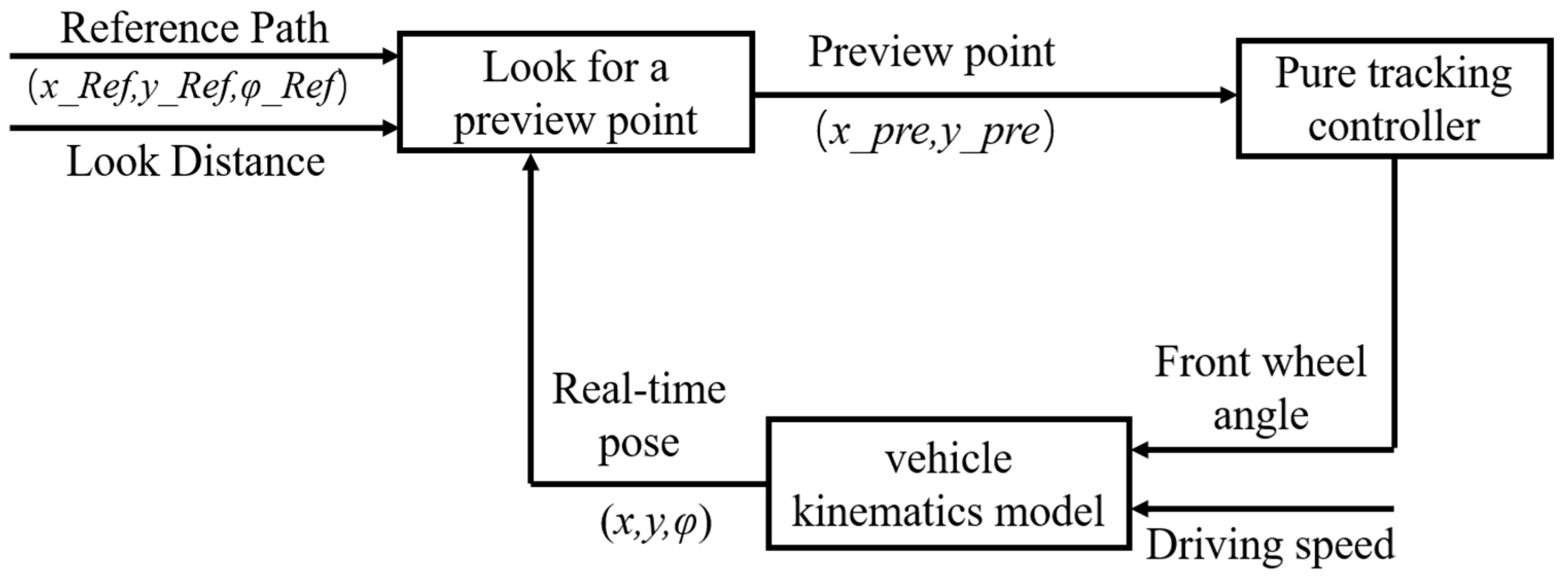
This paper designs a path tracking controller based on the pure tracking model. The schematic diagram of the path tracking controller is shown in Figure 1. The main principle: first obtain the reference path information, then use the current vehicle pose and the reference path pose as the input of the path tracking controller, obtain the desired front wheel angle through the path tracking controller, and finally complete the steering of the front wheel angle through the steering actuator action, so as to realize the 4WS agricultural machinery to complete the path tracking control.

2.1. Establishment of 4WS Vehicle Kinematics Model

Considering the low speed of 4WS agricultural machinery and the small-angle steering adjustment during the driving process, the vehicle dynamics factors are generally not considered [19,20,21]. Based on the kinematics model of agricultural machinery, this paper studies the path tracking algorithm for autonomous navigation of agricultural machinery. The establishment of the kinematic model is based on the following assumptions:
  • Assume that the vehicle is a moving object on a two-dimensional plane;
  • Assuming that the tires on both sides of the vehicle have the same speed and steering angle during driving, the left and right tires of the vehicle are regarded as one tire, and the same is true for the rear wheels;
  • It is assumed that the speed of the vehicle changes slowly, and the transfer of the front and rear axle loads is ignored;
  • Assume that the vehicle is a rigid body;
  • It is assumed that the vehicle steering is four-wheel steering.
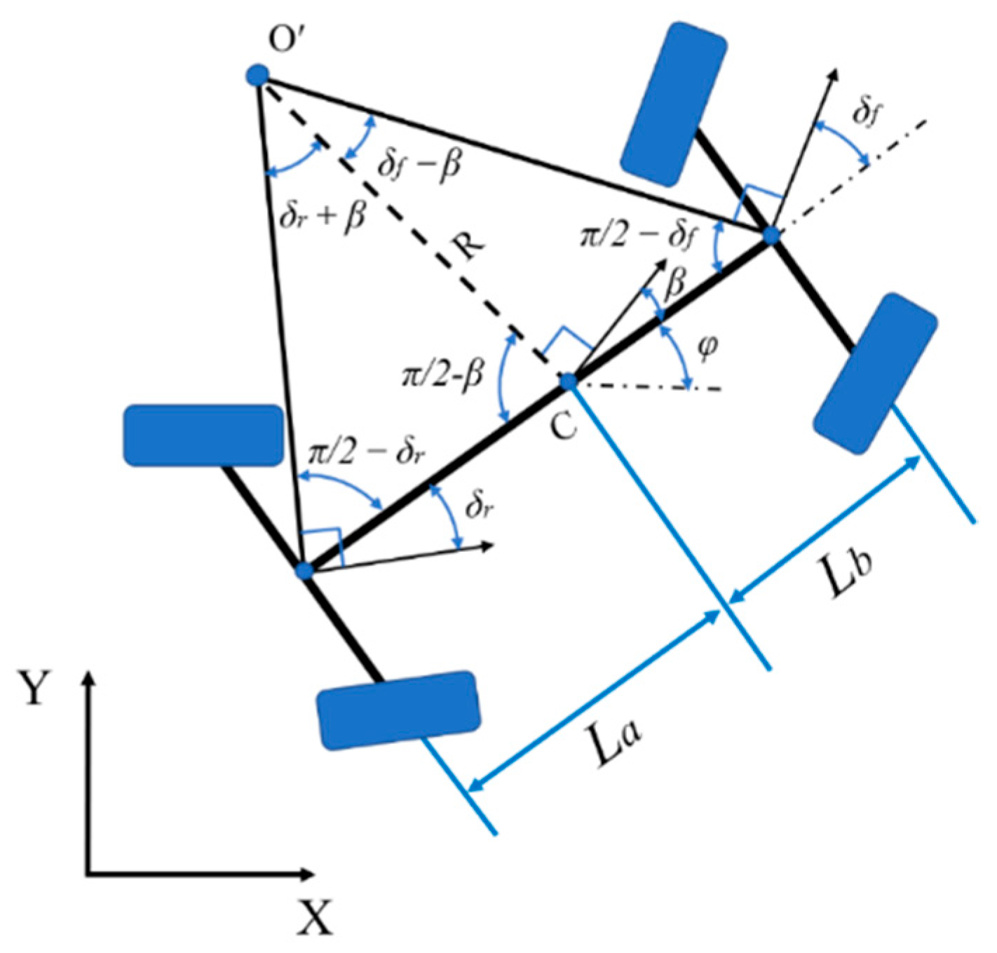
Based on the above assumptions, a vehicle kinematics model is established. Figure 2 shows the 4WS wheel kinematics model.
Among them, in the Cartesian coordinate system XOY:
O′ is the instantaneous center point of the vehicle, which is the intersection of O′A and O′B; β is the lateral eccentricity angle of the center of mass, which is the angle formed by the velocity direction of the center of mass of the vehicle and the body orientation; φ is the heading angle, which is the angle between the forward direction of the vehicle and the X-axis; C is the center of mass of the vehicle, with coordinates (x, y); V is the velocity of the center of mass of the vehicle; La is the distance from the center point of the wheelbase of the rear wheels of the vehicle to the center of mass of the vehicle C; Lb is the distance from the center point of the wheelbase of the front wheels of the vehicle Lb is the distance from the center point to the center of mass C of the vehicle; δf is the front wheel steering angle; δr is the rear wheel steering angle.
Based on the kinematic model of a four-wheel steered vehicle, the analytical geometry of the sine theorem is given in Equations (1) and (2).
L a sin ( δ r + β ) = R sin ( π 2 δ r )
L b sin ( δ f β ) = R sin ( π 2 δ f )
Expanding the equation yields (3) and (4).
L a R = sin ( δ r + β ) sin ( π 2 δ r ) = sin δ r c o s β + s i n β c o s δ r c o s δ r = tan δ r cos β + sin β
L b R = sin ( δ f β ) sin ( π 2 δ f ) = s i n δ f c o s β sin β c o s δ f c o s δ f = tan δ f cos β sin β  
where the front and rear wheelbase L of the 4WS vehicle kinematic model is calculated as (5).
L = L a + L b
The angular velocity of the vehicle’s transverse pendulum is (6).
φ ˙ = ω = V R
Combining these equations gives (7).
φ ˙ = V ( tan δ f + tan δ r ) cos β L
In the inertial coordinate system XOY, the vehicle kinematic model calculates the result obtained as (8).
{ X ˙ = V cos ( φ + β ) Y ˙ = V sin ( φ + β ) φ ˙ = V ( tan δ f + tan δ r ) cos β L
In Ackermann’s low-speed four-wheel steering model, under low-speed conditions, it is generally believed that no lateral sliding occurs, so β ≈ 0. When performing the four-wheel steering action, the 4WS agricultural machine in this paper uses a fully hydraulic system for steering, and it is theoretically believed that the front wheel turning angle δf and the rear wheel turning angle δr are of the same size, so the 4WS vehicle kinematic model further yields the result (9).
{ X ˙ = V cos φ Y ˙ = V sin φ φ ˙ = 2 V tan δ f L

2.2. 4WS Pure Tracking Algorithm Control Principle

The pure tracking algorithm is based on a geometric model of the vehicle and is derived on the basis of Ackermann’s steering principle, which derives the front wheel turning angle from the vehicle steering kinematics [22,23,24]. The main principle: the center position of the vehicle’s rear axle wheelbase is used as the base point and the front sight distance is used as the radius to find the pre-targeting point on the reference path (assuming that the vehicle arrives at the pre-targeting point from its initial position along the turning radius circular trajectory), and then the desired front wheel turning angle is determined based on the vehicle’s front sight distance, the vehicle’s current position, the vehicle’s wheelbase, and the geometric relationship with the pre-targeting point. The framework of the traditional pure tracking algorithm is shown in Figure 3. The 4WS pure tracking model is shown in Figure 4.
As shown in Figure 4, the 4WS pure tracking algorithm takes the center point G of the front and rear wheelbase of the vehicle as the reference point, R as the turning radius, C as the pre-targeting point, Ld as the forward-looking distance, L as the front and rear wheelbase of the vehicle, α as the angle between the body heading and the pre-targeting point C, and δ as the front wheel turning angle. In the triangle GO′C, Equation (10) is obtained by calculation of the sine theorem.
L d sin 2 α = R sin ( π 2 α )
From Equation (11) we get α.
α = arcsin ( y p r e y x p r e x ) φ
In the Ackermann low-speed attitude model with four-wheel steering, (12) is obtained according to the Ackermann steering principle.
tan δ = L 2 R
Solving Equation (10), Equation (12) together gives (13).
δ = arctan ( L sin α L d )
In Equation (13), δ is the desired front wheel turning angle and Ld is the pre-sight distance. The desired front wheel turning angle δ is mainly controlled by the pre-sight distance Ld to make the decision, so as to achieve the trajectory tracking of the reference path.

2.3. Simulation of 4WS Pure Tracking Algorithm

The simulation model is built in Simulink based on the above four-wheel steering pure tracking algorithm. The simulation model mainly contains the pre-targeting point query module, 4WS vehicle kinematic model, and 4WS pure tracking model.
Pre-sighting point finding module: It consists of two parts: pre-sighting point finding and pre-sighting point determination. According to the current vehicle position, vehicle forward-looking distance, and reference path point information, the pre-targeting point is found by the traversal method, and then the pre-targeting point is determined by determination.
4WS vehicle kinematic model: The input quantity is the actual front wheel rotation angle and current speed, and the output quantity is the current position of the vehicle (including x coordinate, y coordinate, and heading angle φ).
4WS pure tracking model: The input quantities are the current position (including x coordinate, y coordinate, and heading angle φ), the pre-targeting point, and the travel speed. The output is the desired front wheel rotation angle.
After integrating the above components, the resulting 4WS pure tracking simulation model is shown in Figure 5.
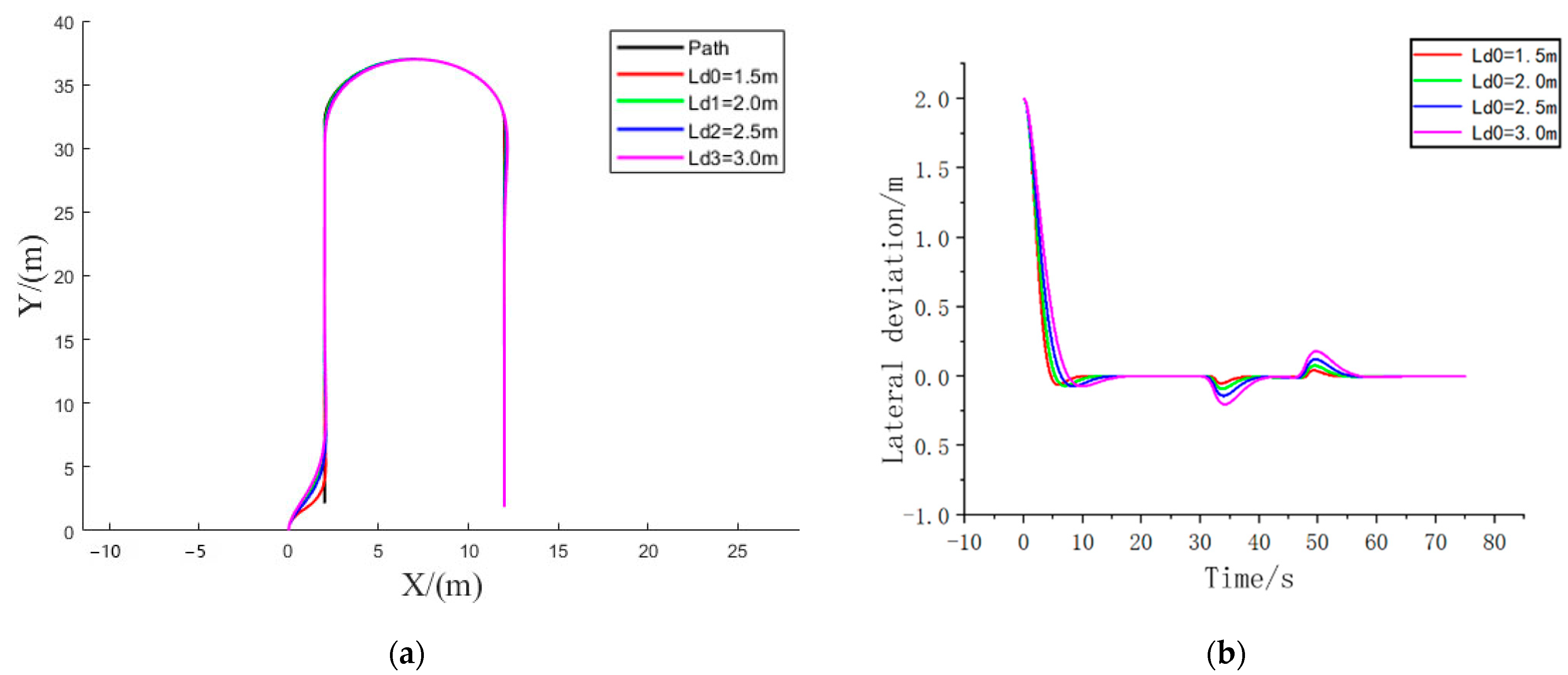
Under the condition of certain speed, only the pre-sighting distance is changed to observe the tracking effect under different working conditions. Specific simulation conditions are set: the vehicle driving speed is 1.2 m/s, and different forward-looking distance is used for simulation, respectively. The forward-looking distance is 1.5 m, 2.0 m, 2.5 m, and 3.0 m. Where the path tracking curve is shown in Figure 6a, the lateral deviation is shown in Figure 6b, and Figure 7a,b are the local enlargements of the path tracking curve graphs A and B, respectively. It is obvious that there is a large tracking error at the turn.
From the above path tracking diagram, it can be seen that the pure tracking algorithm has good tracking effect in the straight line tracking process. In the local enlargements of A and B, it is obvious that the tracking error is larger at the turn. At the same time, the tracking effect has different tracking effects under different conditions of front sight distance, and it can be obtained that the tracking effect of the pure tracking algorithm mainly depends on the sight distance, and the difference for the pre-sighting point leads to the difference of tracking effect.
The forward-looking distance of a pure tracking algorithm is generally represented by (14).
L d = K V V + L d 0
where Kv is the vehicle speed gain coefficient, V is the current driving speed, and Ld0 is the lower limit value of the forward-looking distance (minimum forward-looking distance). This simulation uses fixed front view distance at a certain speed, respectively, to analyze the tracking effect of different front view distances, and does not consider the effect of vehicle speed on the front view distance.

3. Improvement of Pure Tracking Algorithm Based on Fuzzy Control

As the main adjustable parameter of a pure tracking algorithm, the foresight distance is relatively difficult to obtain [25,26,27,28,29,30]. When the forward-looking distance of the traditional pure tracking model is a fixed value, and the vehicle speed and the curvature of the reference path change greatly, the tracking accuracy of the vehicle will be reduced. The assembly causes the tracking error of the path to be too large at the next moment. Therefore, when the agricultural machinery uses the pure tracking control algorithm, obtaining the appropriate distance online according to the driving state of the agricultural machinery is the key to ensuring the accuracy of the pure tracking model path tracking control. In this paper, through the design of the fuzzy controller, the heading deviation and the lateral deviation are converted into the sum of the lateral deviation in one control cycle (represented as a synthetic error) as the first input, the vehicle speed is used as the second input, and the forward sight distance is set as the output, and in this way, the influence of lateral deviation, heading deviation and driving speed can be comprehensively considered, so as to output the matching foresight distance.

3.1. Design of Fuzzy Control Input and Output

(1)
Synthesis error
Considering that when the agricultural machinery performs path tracking, in addition to the driving speed, both the heading deviation and the lateral deviation have an impact on the selection of the foresight distance, so the sum of the lateral deviations converted from the heading deviation and the lateral deviation in one control cycle is taken as the synthetic error, as one of the inputs to the fuzzy controller. The synthetic error Err is calculated from Equation (15).
E r r = e d + V · Δ T · sin ( e φ )
In the formula: V is the speed of the vehicle; ed is the lateral deviation; is the heading deviation; ΔT is the control period, and ΔT is taken as 0.01 in this simulation test.
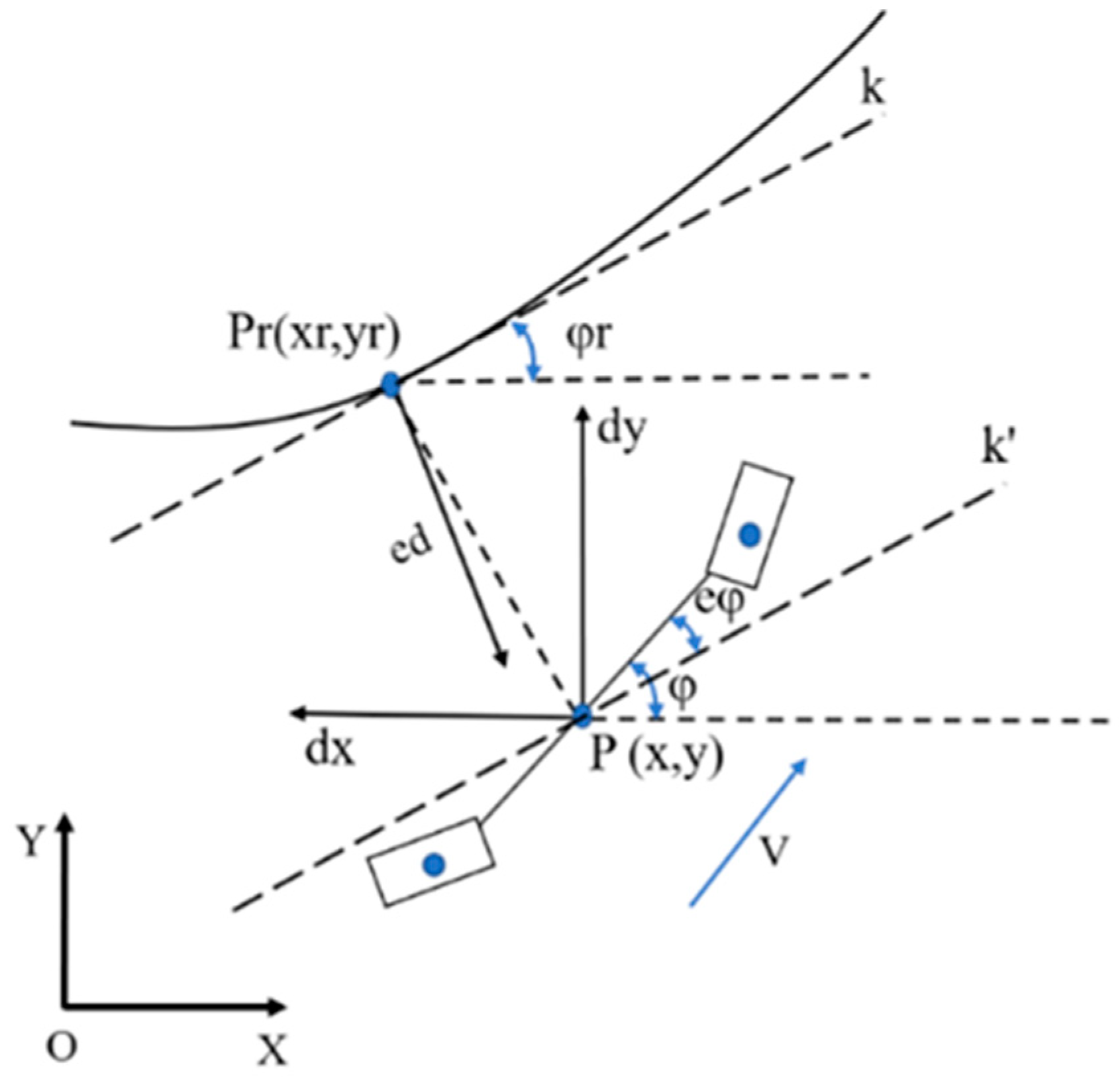
The path tracking error is shown in Figure 8, where Pr(xr, yr) is the preview point from the vehicle position, and P(x, y) is the real-time position point during the vehicle tracking process. eφ is the heading deviation of path tracking, and ed is the lateral deviation of path tracking. k is the tangent of the Pr point, and k’ is the parallel line of k at the real-time position of the vehicle.
As can be seen in Figure 8, the heading deviation ed and the lateral deviation are calculated as (16) and (17), respectively.
{ d x = x x r d y = y x r
{ e d = d x cos φ r d y sin φ r e φ = φ φ r  
(2)
System universe design
The synthetic error Err and the vehicle body speed V are used as the two inputs of the fuzzy controller, the front sight distance Ld is used as the output, and the fuzzy language value is:
Synthesis error Err, the unit is m; the basic domain is [−0.6, 0.6]; the fuzzy subset is defined as {NB, NM, NS, O, PS, PM, PG}; the representative meaning is {Negative Large, Negative Medium, Negative Small, Zero, Positive Small, Positive Middle, Positive Large}.
The vehicle body speed V, in m/s; the basic domain is [0.5, 3]; the fuzzy subset is defined as {VS, S, M, B, VB}; the representative meaning is {Very Small, Small, Medium, Large, Very Big}.
The look-ahead distance Ld, the unit is m; the basic domain is [1, 4]; the fuzzy subset is defined as {VS, S, M, B, VB}; the representative meaning is {Very Small, Small, Medium, Large, Very Big}.

3.2. Design of Fuzzy Control Rules

When the vehicle is driving, an excessively large forward-looking distance will cause the agricultural machinery to steer in advance when approaching a turning point during driving, and a too small forward-sighted distance will oscillate back and forth around the reference path. When designing rules, the influence of tracking error and vehicle speed should be considered, and the following rules should be used to design:
(1) When the driving speed of the vehicle is constant and the synthetic error in the tracking process is large, the forward-looking distance should be selected with a large value to ensure the driving stability of the vehicle.
(2) When the synthetic error in the tracking process is constant and the vehicle speed is large, the forward-looking distance should be selected to a larger value to ensure the stability of the vehicle.
Based on the above rules, the fuzzy control rule table (Table 1) and the fuzzy control surface graph (Figure 9) are obtained.
For fuzzy control, there are three commonly used clearing methods: the center of gravity method, the weighted average method, and the maximum membership degree method. In this paper, the center of gravity method is used to clarify the output variables.

3.3. Simulation of Pure Tracking Algorithm for Fuzzy Control

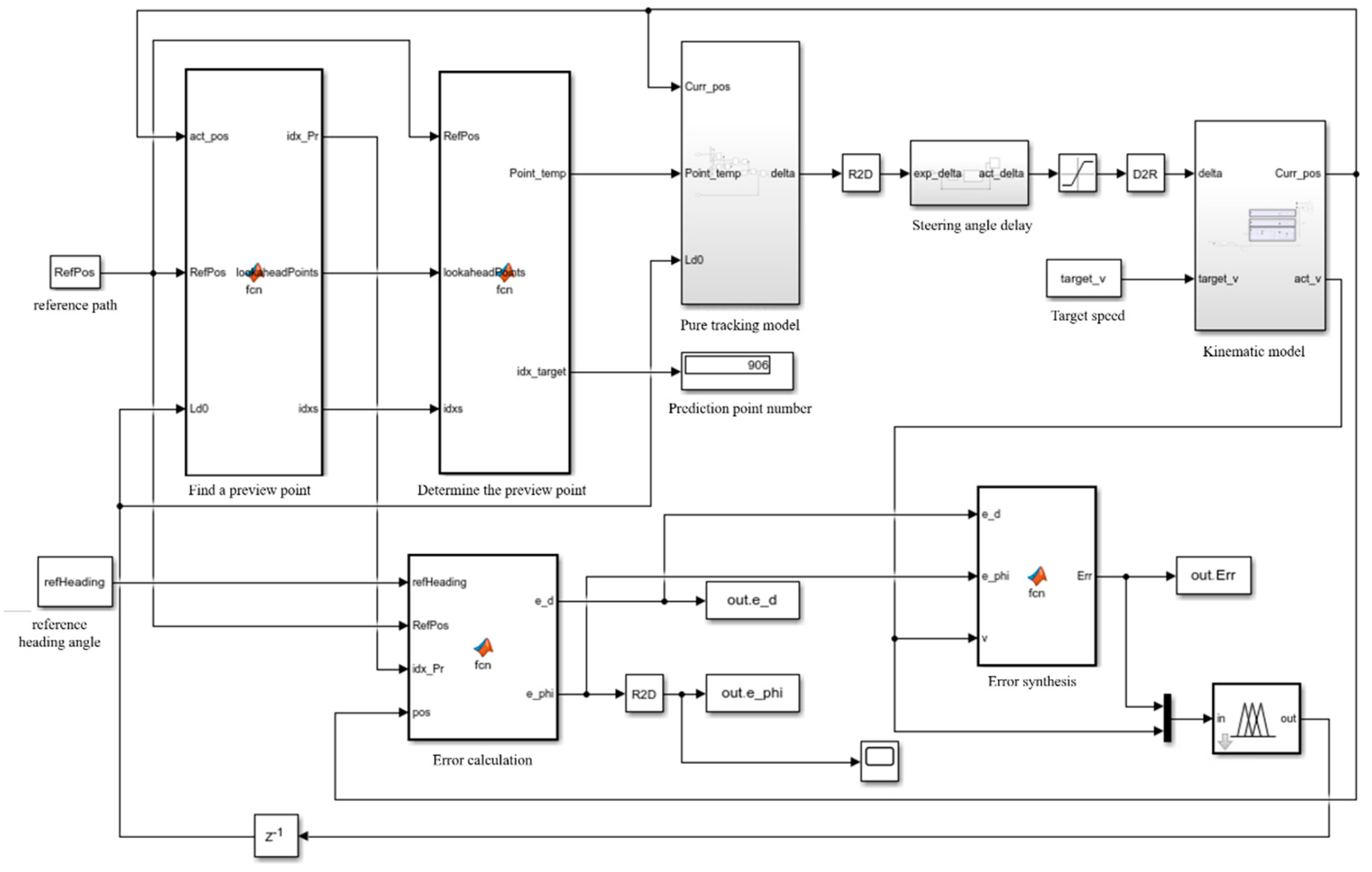
The flow chart of the path tracing simulation is shown in Figure 10. The specific process is as follows:
(1) Enter the reference path state information Refpose, which contains the amount of reference state for each point in the reference path;
(2) Calculate the combined error Err through the error calculation module, and the combined error is the sum of the lateral deviation converted into the heading deviation and the lateral deviation in one control cycle;
(3) Convert the vehicle speed V and the synthetic error Err into the forward-looking distance Ld through the fuzzy controller;
(4) Taking the forward-looking distance Ld, the reference path state information RefPose, and the implementation state pose information Pose as the input of the pure tracking model, the expected front wheel rotation angle is calculated;
(5) Input the expected front wheel angle into the vehicle kinematics model, and the vehicle real-time state quantity Pose is updated.
The above processes (1), (2), (3), (4), and (5) are cycled in turn, and the real-time state quantity Pose of the vehicle is continuously updated.
In order to verify the feasibility of the path tracking algorithm proposed in this paper, according to the design of the fuzzy control pure tracking algorithm and the simulation flow of path tracking, the simulation model of the path tracking algorithm is established in Matlab/Simulink, and the simulation test is carried out. The simulation model of the fuzzy control pure tracking algorithm is shown in Figure 11.

3.4. Work Path Planning

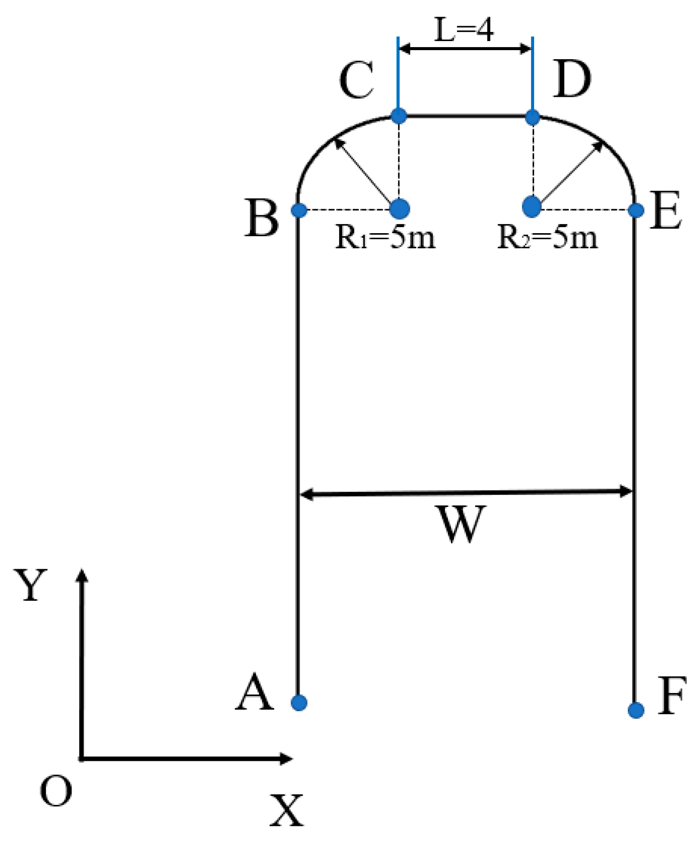
In this paper, the agricultural machinery is mainly designed and developed according to the working requirements of the plant protection machine, and its autonomous navigation working path is planned according to the walking path requirements of the plant protection machine when it is working. The full length of the rear suspension spray bracket of the plant protection machine can reach 10 m, the spray width W can reach 12 m, and the minimum turning radius R of the agricultural machine is 4.5 m, which satisfies the condition of 2R < W. When agricultural machinery operates in the process of autonomous navigation, it needs to complete the actions of straight-line path tracking, headland turning, U-turn, etc., so as to complete the tracking of the entire working path. For this reason, in the process of autonomous navigation of agricultural machinery, the ground spraying work can be evenly completed to ensure a complete coverage area, and the specific working path needs to be planned in combination with the bow turning method. The working path is shown in Figure 12, in which the headland turning radius section R1 = R2 = 5 m, and the U-turn transition section L = 4 m. This working path can meet the needs of agricultural machinery autonomous navigation work.

3.5. Analysis of Simulation Results

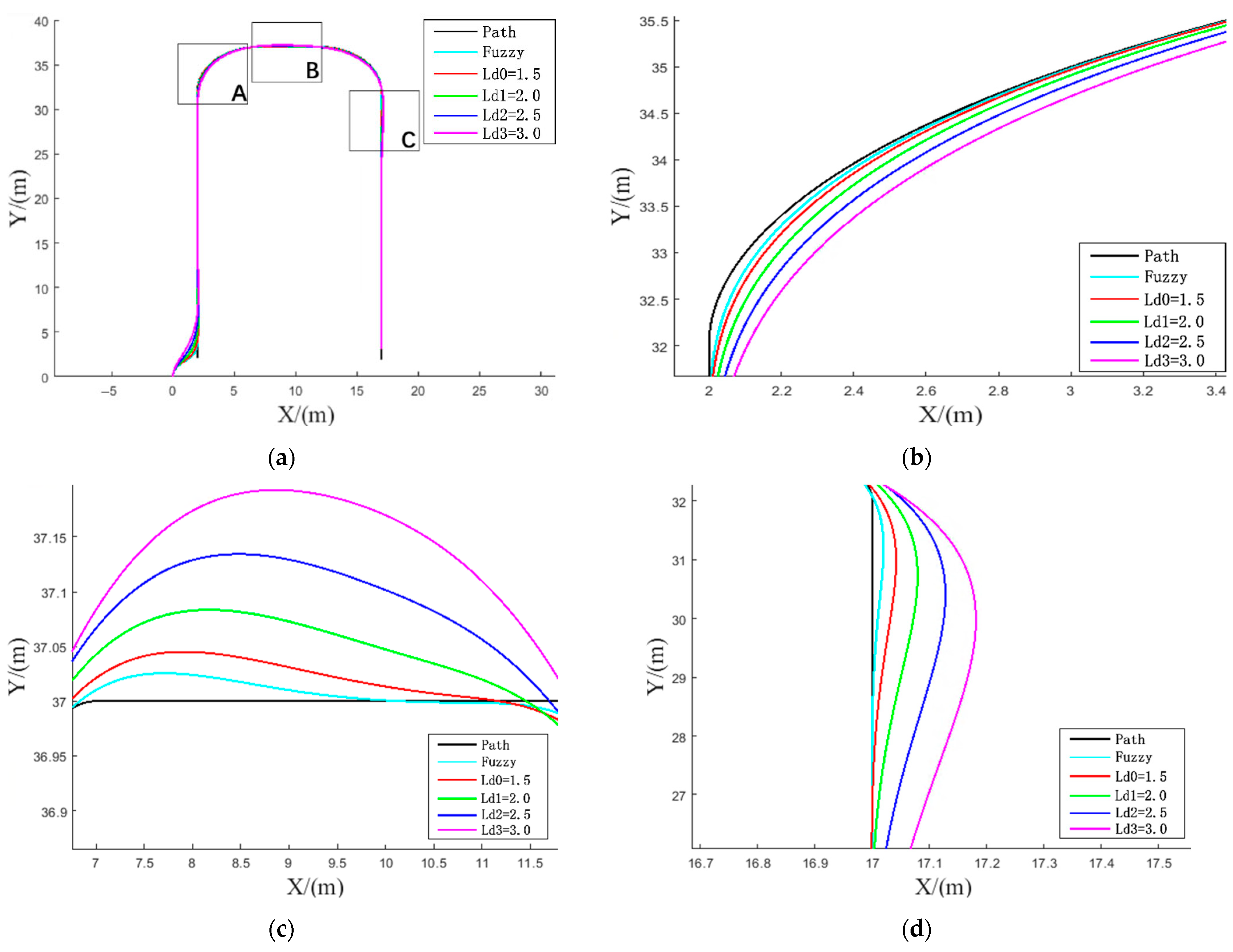
The initial position of the proposed vehicle is (0, 0), and the initial heading angle is set to 90°. Use different forward-looking distances to track the reference working path, and obtain the data of path tracking, lateral deviation change, and front-wheel turning angle change during vehicle driving. The simulation data based on the pure tracking algorithm based on fuzzy control and the traditional pure tracking algorithm are compared, and the error changes are analyzed. Among them, in the traditional pure tracking model, the vehicle speed is 1.2 m/s, and the forward-looking distance is set to 1.5 m, 2.0 m, 2.5 m, and 3 m; in the fuzzy control pure tracking algorithm, the vehicle speed gradually increases from 0 m/s to 4 m/s. The foresight distance is mainly output by the fuzzy controller. The output range of the foresight distance is [1 m~4 m], and the simulation analysis is carried out in the same reference working path segment. Figure 13a is the effect diagram of the path tracking, and Figure 13b–d are the partial enlargement of the turning section A, the U-turn transition section B, and the regression straight section C during the path tracking process, respectively, picture.
For the above-mentioned bow-shaped turning path, both the fuzzy control pure tracking algorithm and the traditional pure tracking algorithm can complete straight-line tracking and have good tracking results in the tracking of straight line sections, but for the turning sections, over-turning sections and returning to straight driving sections, the tracking effect of the fuzzy control pure tracking algorithm is better than that of the traditional pure tracking algorithm, and the straight-line path tracking can be quickly achieved in the over-turning section A and the regression line section C.
The variation of lateral deviation for the five sets of simulation experiments is shown in Figure 14. The peak lateral deviation plots are shown in Figure 15a, and the average lateral deviation pairs at A, B, and C in Figure 13 are shown in Figure 15b–d. In the whole tracking process of the bow turn path, the fuzzy control pure tracking algorithm has the smallest lateral deviation with the peak value of 0.034 m, and the traditional pure tracking algorithm has the peak values of 0.054 m, 0.091 m, 0.141 m, and 0.202 m under different forward-looking distance conditions. The deviation is the smallest, 0.023 m, 0.018 m, and 0.011 m, respectively, and the tracking accuracy advantage is more obvious, which can directly reflect the good effect.
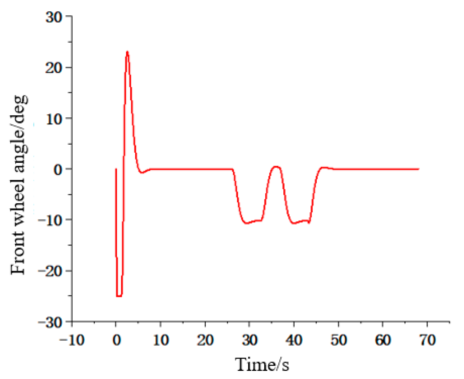
The change in the front wheel angle is shown in Figure 16. For the above conditions, in the tracking process, the front wheel turning angle change amplitude of the control method proposed in this paper is in a reasonable range, the front wheel turning angle is smoother in the turn, and there is no obvious oscillation in the turning curve, which can ensure the smoothness of the agricultural machine in the process of autonomous navigation.

4. Real Vehicle Test and Result Analysis

In this paper, the path tracking control algorithm is improved and optimized, and the simulation test of the 4WS agricultural machine path tracking control algorithm is conducted, and the test proves the effectiveness of the control algorithm. In order to further verify the feasibility of the designed 4WS agricultural machine path tracking algorithm, this paper will carry out the real vehicle test by the built autonomous navigation 4WS agricultural machine test platform. Straight path segment tracking and short tracking of turning paths are carried out to obtain tracking data during the autonomous navigation driving of farm machinery, and the tracking data are analyzed to observe the tracking effect during the autonomous navigation driving of farm machinery.

4.1. 4WS Agricultural Machinery TEST Platform

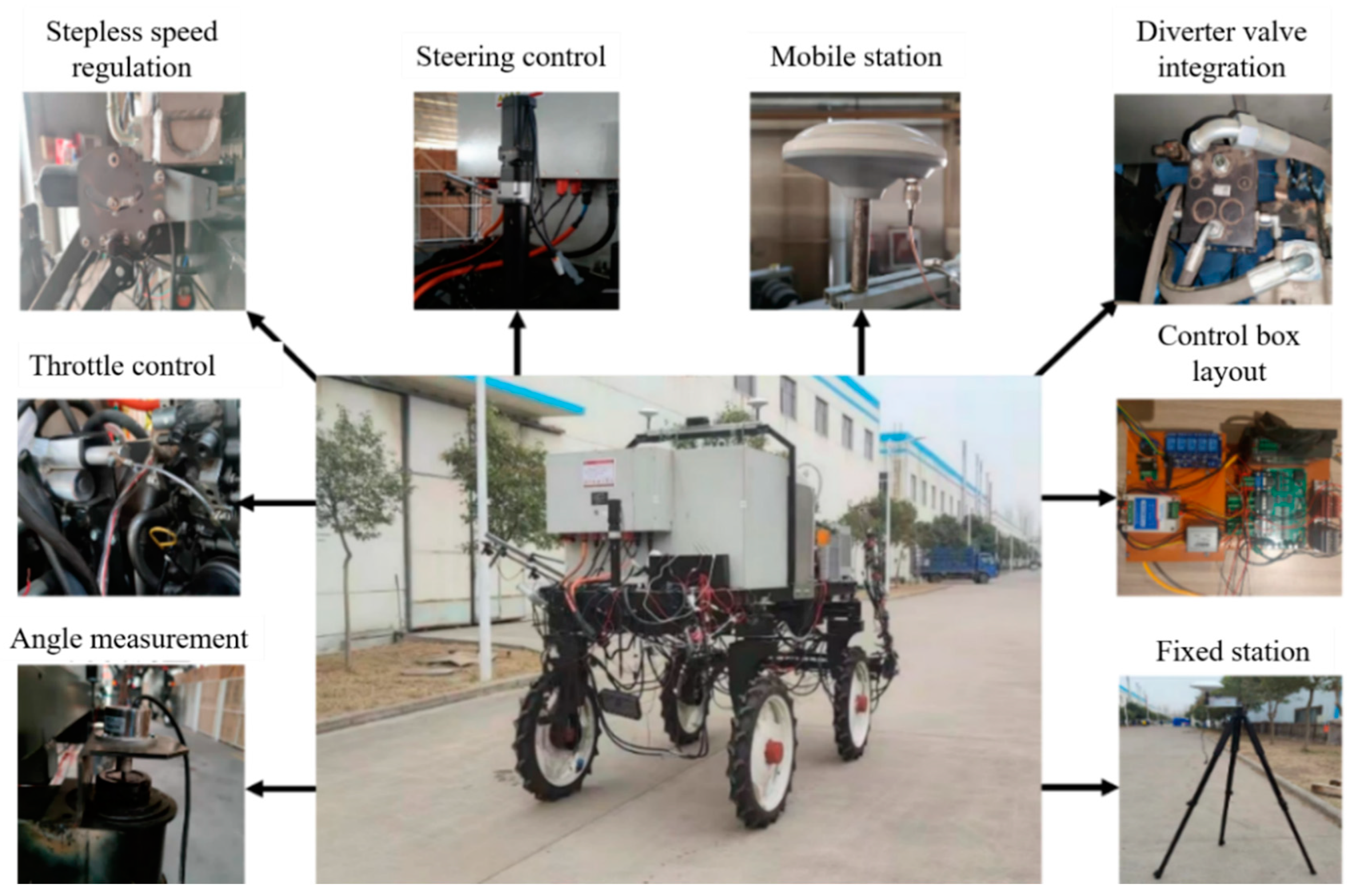
The autonomous navigation 4WS agricultural machine test platform is shown in Figure 17. The important parameters of the 4WS agricultural machinery are shown in Table 2. The test platform is mainly built based on two aspects of a four-wheel drive walking hydraulic system and autonomous navigation system, mainly including a speed regulation and control device, navigation and positioning device, automatic steering device, control box, etc.

4.2. Straight Line Path Tracking Test

The experimental site of linear path tracking in this paper is shown in Figure 18a, and the algorithm of this paper is verified according to the actual working requirements, taking into account the influence of the integrated error and driving speed on the path tracking effect proposed in this paper. The navigation and positioning system in this paper adopts the northeast sky coordinate system, with the fixed station as the origin coordinate, the due north direction as the y-axis coordinate and the due east direction as the x-axis coordinate, and the coordinate system schematic diagram is shown in Figure 18b.
In this experiment, the traditional pure tracking algorithm and the algorithm proposed in this paper are made to do real vehicle autonomous navigation control tests.
Test 1: Under the driving condition of 1.2 m/s speed, the pure tracking algorithm simulation tracking effect is good when the front view distance is 1.5 m, so the forward speed V is 1.2 m/s and the front view distance Ld is 1.5 m as the real vehicle test condition, and the constant speed fixed front view distance linear path section tracking test is conducted.
Test 2: Considering that the foresight distance in the algorithm proposed in this paper is mainly through the integrated deviation and driving speed as the input decision output of the fuzzy controller, the variable speed dynamic foresight distance linear path tracking test is conducted, and the speed change interval is [0.5 m/s~2 m/s].
Set linear path start point A (2, 2), termination point B (2, 37) agricultural machine starting position to linear path AB lateral deviation of about 0.5 m, the body, and linear path AB parallel, that is, the heading angle is 90°, linear section path tracking lateral deviation as shown in Figure 19, lateral deviation data comparison table is shown in Table 3.
Analyzing the data comparison table of the lateral deviation of the tracking trajectory of the straight line section of the 4WS agricultural machine, we can see that in test one, the speed is 1.2 m/s, the forward-looking distance is 1.5 m, the lateral deviation from the straight line AB is 0.5 m, the heading angle is 90 degrees, the agricultural machine carries out autonomous navigation process, reaches the straight line position when the driving distance is 8.84 m, and at the same time produces part of the overstrip, the maximum overstrip is 0.164 m, after which the straight line was tracked steadily, and the maximum lateral deviation of the straight-line tracking part was 0.094 m and the steady-state deviation was 0.061 m after steady driving. In test 2, in the variable speed, dynamic forward-looking distance, the lateral deviation from the straight line AB was 0.5 m, and the initial heading angle was 90°, the process of autonomous navigation by the farm machine reached the straight line position at the driving distance of 6.68 m, and some overshoot is generated at the same time, with the maximum overshoot of 0.123 m, after which the straight line is tracked steadily, and the maximum lateral deviation of the straight line tracking part is 0.058 m and the steady-state deviation is 0.039 m after steady driving.
Through the above experimental comparison, it can be seen that the path tracking control algorithm proposed in this paper has a good tracking effect in the process of straight-line path tracking, and has good adaptability to the speed size, while the corresponding speed of convergence to the desired path is faster, the overstripping amount is small, and the maximum lateral deviation is small in stable tracking, which can enable the 4WS agricultural machine to stably realize the autonomous navigation function of straight-line section.

4.3. Turning Path Tracking Test

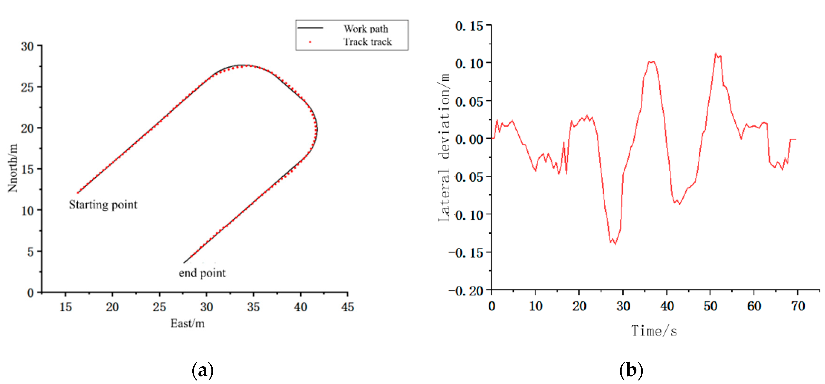
In order to meet the path tracking needs of fieldwork, the path tracking test of the bow route is conducted for the autonomous navigation path tracking control method proposed in this paper. In this test, the driving speed of the straight line section is 1.5 m/s, and the speed of the turning section is slowed down to 1 m/s. Figure 20a shows the path tracking for the bow turn section and Figure 20b shows the lateral deviation.
In the process of bow turn path tracking, the maximum lateral deviation of the actual driving trajectory of agricultural machinery and the desired path is 0.139 m in absolute value, and the average tracking deviation is 0.041 m. Among them, the maximum lateral deviation occurs at the turn, but it can quickly approach the desired path. It can be seen that the autonomous navigation path tracking algorithm proposed in this paper can stably track the bow-shaped curve with a good tracking effect, which meets the path tracking requirement of agricultural machinery and provides good tracking conditions for the subsequent intelligent operation function.
Through the 4WS agricultural machinery test platform autonomous navigation test, the straight-line path tracking test and the turning path tracking test were completed respectively, and the test showed that the control method proposed in this paper has good tracking accuracy and can meet the demand of the 4WS agricultural machinery autonomous navigation function.

5. Discussion

The article addresses the problem of autonomous navigation path tracking motion control of agricultural machinery and proposes a 4WS agricultural machinery path tracking algorithm based on a fuzzy control pure tracking model, and verifies the feasibility of the 4WS agricultural machinery path tracking algorithm proposed in this paper by comparing it with traditional pure tracking algorithms, four-wheel steering, and two-wheel steering, and with others’ pure tracking algorithms.
1.
Traditional pure tracking algorithm comparison
The traditional pure tracking algorithm only considers tracking under fixed forward-looking distance conditions or adaptive adjustment of forward-looking distance according to speed. The algorithm proposed in this paper considers a certain degree of predictiveness by calculating the influence of lateral deviation and heading deviation in the next sampling period under the current speed and obtains a combined deviation to output dynamic forward-looking distance through the fuzzy controller for decision-making. The fuzzy controller is edited according to the fuzzy rules to output the forward-looking distance.
2.
Comparison of four-wheel steering and two-wheel steering
This study combines the characteristics of four-wheel steering of the hydraulic chassis of a plant protection machine and establishes a four-wheel steering kinematic model according to Ackermann’s four-wheel steering principle (low-speed attitude), which has the characteristics of a small turning radius compared with two-wheel steering and can improve the driving stability during vehicle tracking. At the same time, it can reduce the damage to crops caused by the large turning radius during the agricultural operation of the real vehicle.
3.
Comparison with other pure tracking algorithms
Pure tracking algorithm forward-looking distance decision method: fuzzy control, PSO particle swarm, speed regulation method.
In fuzzy control: most of them consider lateral deviation and heading deviation decisions to output desired front wheel turning angle, or lateral deviation and speed decision to output the front wheel turning angle, and only two control parameters are considered. This study outputs desired front wheel turning angle by fuzzy controller decision through three control parameters of lateral deviation and heading deviation and speed V. PSO particle swarm: it is poorly handled for discrete optimization problems and easy to fall into local optimum. Decision by formula: Most of them only consider the single factor of speed.
In addition, in this paper, the 4WS agricultural machine path tracking control algorithm is simulated and the test proves the effectiveness of the control algorithm. In order to further verify the feasibility of the designed 4WS agricultural machine path tracking algorithm, this paper will conduct real vehicle tests through the built autonomous navigation 4WS agricultural machine test platform. Straight path segment tracking and short tracking of turning path are carried out to obtain tracking data during the autonomous navigation driving of farm machinery, and the tracking data are analyzed to observe the tracking effect during the autonomous navigation driving of farm machinery. The experiment shows that the path tracking algorithm of the 4WS agricultural machine based on the pure tracking model of fuzzy control proposed in this paper has good tracking accuracy and can meet the demand for autonomous navigation function of the 4WS agricultural machine, which has a certain application value in autonomous navigation of agricultural machine.

6. Conclusions

The path tracking algorithm of 4WS agricultural machinery based on the fuzzy control pure tracking model proposed in this study can effectively improve the driving stability as well as the tracking accuracy in the tracking process of agricultural machinery. The fuzzy control pure tracking algorithm is designed for 4WS agricultural machinery. With the small turning radius characteristic of the agricultural machinery in this study, the pure tracking algorithm is combined with the fuzzy controller to output the actual forward-looking distance by taking into account the influencing factors of lateral deviation, and speed in the tracking process of 4WS agricultural machinery. The results show that the 4WS path tracking algorithm with a pure tracking model of local fuzzy control has a good tracking effect for 4WS agricultural machinery.
Compared with the tracking algorithm proposed in the literature [10], the literature [11], and the literature [14], the algorithm in the literature [10] only considers the tracking state of 2WS steering agricultural machinery, which is suitable for the model of two-wheel steering and completes the path tracking of agricultural machinery combined with preview control. In this algorithm, it shows a good tracking effect in the process of straight-line path tracking. In reference [11], in order to improve the robustness and stability of agricultural machinery in the tracking process at different speeds, the chain system model is combined with small-scale stability analysis and optimization, so as to improve the driving stability and tracking accuracy in the linear path tracking process at different speeds. In the document [14], a fuzzy PID controller is used, with the error of the synthesis of heading deviation and lateral deviation as the input, the rotation angle of the front wheel as the output, and the kinematic model as the benchmark, to design a path tracking algorithm for agricultural machinery. Finally, taking the rice transplanter as the test platform, tests are carried out on asphalt pavement and paddy field pavement, respectively, and the tracking accuracy can meet the needs of precision agriculture of the rice transplanter. In this study, by analyzing the kinematic characteristics of 4WS agricultural machinery, geometric analysis is carried out, and the 4WS kinematic model is established, as shown in Figure 2. Considering that the heading deviation and lateral deviation have an impact on the selection of forward-looking distance in addition to the driving speed when the agricultural machinery tracks the path, the sum of the lateral deviation converted by the heading deviation and lateral deviation in a control cycle is taken as the synthetic error, which mainly takes into account the predictability in the driving process and is used to reduce the hysteresis caused by the hydraulic driving system of 4WS agricultural machinery, as shown in formula 15. The synthetic error is the input one of the fuzzy controller, and the driving speed is the input two of the fuzzy controller so that the previous life distance can be decided and output, and finally the desired front wheel angle can be output through the pure tracking model. Compared with the algorithm given in the literature [13], and in the literature [12], under the condition of adaptive speed change, the improved particle swarm optimization algorithm is used to dynamically adjust the forward-looking distance based on the deviation degree of the vehicle body, so as to obtain the appropriate forward-looking distance. The steering angle of the front wheel is output through the pure tracking algorithm, and the horizontal deviation value is large in the process of speed change linear tracking. In contrast, the 4WS agricultural machinery path tracking algorithm designed in this study has better tracking accuracy in straight-line tracking sections and still has better tracking accuracy under variable speed conditions. The horizontal deviation comparison table difference is shown in Table 3, and the maximum horizontal deviation in the tracking stage in the stable stage is 0.059 m.
In this study, the path tracking control algorithm is improved and optimized, the 4WS agricultural machinery path tracking control algorithm is simulated, and the experiment proves the effectiveness of the control algorithm. At the same time, the straight path tracking test and turning path tracking test are carried out through the designed 4WS agricultural machinery, and the tracking accuracy is evaluated through the horizontal deviation in the tracking process, as shown in Figure 19 and Figure 20b.

Author Contributions

Conceptualization, C.Z. (Chengliang Zhang); writing—review and editing, G.G.; validation, C.Z. (Chunzhao Zhao); supervision, L.L.; formal analysis, C.L.; visualization, X.C. All authors have read and agreed to the published version of the manuscript.

Funding

This work was supported by the Key R&D Program of Shandong Province (2020CXGC011001 and 2020CXGC011003).

Institutional Review Board Statement

Not applicable.

Informed Consent Statement

Not applicable.

Data Availability Statement

Not applicable.

Conflicts of Interest

The authors declare no conflict of interest.

References

  1. Luo, X.; Liao, J.; Zou, X. Information technology to enhance agricultural mechanization. J. Agric. Eng. 2016, 20, 1–14. [Google Scholar]
  2. Liu, Z.; Zhang, Z.; Luo, X. Design of GNSS automatic navigation operation system for Leivol ZP9500 upland gap sprayer. J. Agric. Eng. 2018, 34, 15–21. [Google Scholar]
  3. Li, S.; Xu, H.; Ji, Y.; Cao, R.; Zhang, M.; Han, L. Development of a following agricultural machinery automatic navigation system. Comput. Electron. Agric. 2019, 158, 335–344. [Google Scholar] [CrossRef]
  4. Hu, J.; Gao, L.; Bai, X. Research progress of automatic navigation technology for agricultural machinery. J. Agric. Eng. 2015, 31, 1–10. [Google Scholar]
  5. Ji, C.; Zhou, J. Analysis of the development of agricultural machinery navigation technology. J. Agric. Mach. 2014, 45, 44–54. [Google Scholar]
  6. Xie, B.; Liu, J.; He, M.; Cai, L.; Xu, Z.; Cui, B. Improved AOA model for the design of unmanned navigation parameter detection system for farm machinery in large fields. J. Agric. Eng. 2021, 37, 40–51. [Google Scholar]
  7. Tang, L. Research on automatic navigation technology for agricultural mechanization. Agric. Mach. Sci. Technol. Promot. 2020, 20, 18–19. [Google Scholar]
  8. Zhai, W.; Wang, D.; Chen, Z.; Dong, L.; Zhao, X.; Wu, C. Autonomous operation path planning method for unmanned agricultural machines. J. Agric. Eng. 2021, 37, 1–7. [Google Scholar]
  9. Lan, Y.; Zhao, D.; Zhang, Y.; Zhu, J. Exploration and development prospect of eco-unmanned farm model. J. Agric. Eng. 2021, 37, 312–327. [Google Scholar]
  10. Wang, H.; Wang, G.; Luo, X.; Zhang, Z.; Gao, Y.; He, J.; Yue, B. A pre-targeting tracking model-based path tracking control method for agricultural machine navigation. J. Agric. Eng. 2019, 35, 11–19. [Google Scholar]
  11. Duan, X.; Tao, J.; Qin, C.; Cai, D.; Li, Y.; Liu, C. Stable control method for path tracking of agricultural machinery under variable speed conditions. J. Agric. Mach. 2019, 50, 18–24+32. [Google Scholar]
  12. Bai, X.; Meng, P.; Wang, Z.; Shi, J. A navigation control method for agricultural machinery based on motion characteristics. J. Agric. Mach. 2021, 52, 21–27. [Google Scholar]
  13. Chai, S.; Yao, L.; Xu, L.; Chen, Q.; Xu, T.; Yang, Y. Research on path tracking of greenhouse farm machinery based on dynamic forward-looking distance pure tracking model. Chin. J. Agric. Mach. Chem. 2021, 42, 58–64+79. [Google Scholar]
  14. Jiang, H. Research on Automatic Navigation System of Agricultural Machinery Based on RTK Technology; Zhejiang University: Hangzhou, China, 2019. [Google Scholar]
  15. Bayar, G.; Bergerman, M.; Koku, A.B. Improving the trajectory tracking performance of autonomous orchard vehicles using wheel slip compensation. Biosyst. Eng. 2016, 146, 149–164. [Google Scholar] [CrossRef] [Green Version]
  16. Morales, J.; Martinez, J.; Mandow, A.; Garcia-Cerezo, A.J. Steering the last trailer as a virtual tractor for reversing vehicles with passive on-and off-axle hitches. IEEE Trans. Ind. Electron. 2013, 60, 5729–5736. [Google Scholar] [CrossRef]
  17. Lenain, R.; Thuilot, B.; Cariou, C.; Martinet, P. Adaptive and Predictive path tracking control for off-road mobile Robots. Eur. J. Control. 2007, 13, 419–439. [Google Scholar] [CrossRef]
  18. Backman, J.; Oksanen, T.; Visala, A. Navigation system for agricultural machines: Nonlinear model predictive path tracking. Comput. Electron. Agric. 2012, 82, 32–43. [Google Scholar] [CrossRef]
  19. Thrun, S.; Montemerlo, M.; Dahlkamp, H. Stanley: The robot that won the DARPA grand challenge. J. Field Robot. 2006, 23, 661–692. [Google Scholar] [CrossRef]
  20. Hiraoka, T.; Nishihiara, O.; Kumamo, H. Automatic path-tracking controller of a four-wheel steering vehicle. Veh. Syst. Dyn. 2009, 47, 1205–1227. [Google Scholar] [CrossRef]
  21. Tan, X.; Liu, D.; Xiong, H.; Yin, W.; Pan, Y. 4WS vehicle steering decoupling for dual-point tracking control. Control. Theory Appl. 2022, 3, 32–39. [Google Scholar]
  22. Guo, B.; Du, X.; Tao, X. Algorithm improvement based on pure tracking model. Automot. Pract. Technol. 2019, 15, 32–34. [Google Scholar]
  23. Kapsalis, D.; Sename, O.; Milanes, V.; Molina, M. Design and Experimental Validation of an LPV Pure Pursuit Automatic Steering Controller. IFAC-PapersOnLine 2021, 54, 63–68. [Google Scholar] [CrossRef]
  24. Li, T.; Hu, J.; Gao, L.; Liu, X.; Bai, X. Agricultural machine path tracking method based on fuzzy adaptive pure pursuit model. Nongye Jixie Xuebao/Trans. Chin. Soc. Agric. Mach. 2013, 44, 205–210. [Google Scholar]
  25. Wang, K.; Liu, Y.; Li, Y. Model-based prediction of transverse sway and lateral stability control. Beijing Automot. 2018, 4, 10–13. [Google Scholar]
  26. Li, Y.; Li, S.; Wu, C.; Chen, G. Pure tracking trajectory control based on hardware-in-the-loop simulation implementation. Agric. Mach. Use Maint. 2021, 4, 47–48. [Google Scholar]
  27. Xie, F.; Li, J.; Li, Z.; Lin, Z. Research on path planning and trajectory tracking control of orchard mowing robot. China Trop. Agric. 2021, 26, 16–24. [Google Scholar]
  28. Yu, L.; Yan, X.; Kuang, Z.; Chen, B.; Zhao, Y. Driverless bus path tracking based on fuzzy pure pursuit control with a front axle reference. Appl. Sci. 2019, 10, 230. [Google Scholar] [CrossRef] [Green Version]
  29. Ni, T.; Li, W.; Zhang, H.; Kong, Z. Pose rediction of autonomous full tracked vehicle based on 3D sensor. Sensors 2019, 19, 5120. [Google Scholar] [CrossRef] [PubMed] [Green Version]
  30. Wang, H.; Liu, B.; Qiao, J. Advanced High-Speed Lane Keeping System of Autonomous Vehicle with Sideslip Angle Estimation. Machines 2022, 10, 257. [Google Scholar] [CrossRef]
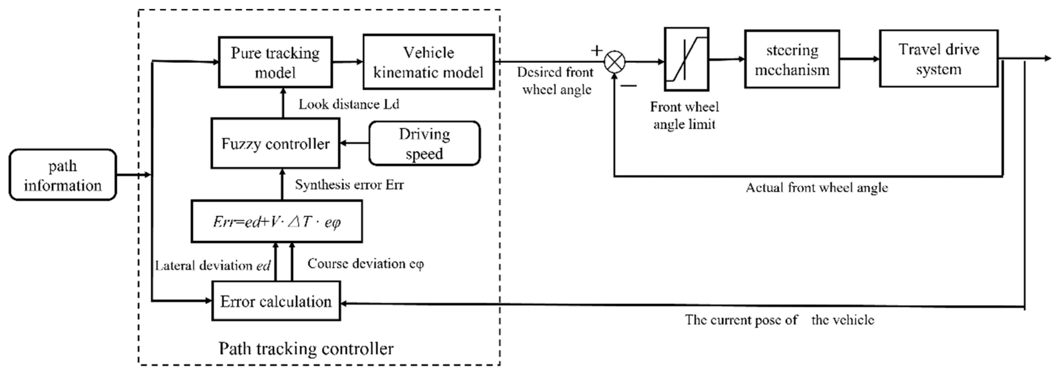
Figure 1. Schematic diagram of the path tracking system.
Machines 10 00597 g001
Figure 2. 4WS vehicle kinematics model.
Machines 10 00597 g002
Figure 3. Framework diagram of traditional pure tracking algorithm.
Machines 10 00597 g003
Figure 4. 4WS pure tracking model.
Machines 10 00597 g004
Figure 5. Simulation model of 4WS pure tracking algorithm.
Machines 10 00597 g005
Figure 6. Traditional pure tracking algorithm path tracking. (a) Path tracking curve; (b) Lateral deviation.
Machines 10 00597 g006
Figure 7. Local enlargement diagram. (a) Partial enlargement at A; (b) Partial enlargement at B.
Machines 10 00597 g007
Figure 8. Lateral deviation and heading deviation.
Machines 10 00597 g008
Figure 9. Fuzzy control surface graph.
Machines 10 00597 g009
Figure 10. Path tracking simulation flow chart.
Machines 10 00597 g010
Figure 11. 4WS pure tracking algorithm simulation model.
Machines 10 00597 g011
Figure 12. Working path.
Machines 10 00597 g012
Figure 13. Pure tracking algorithm of fuzzy control. (a) Bow turn path tracking; (b) Partial enlargement at A; (c) Partial enlargement at B; (d) Partial enlargement at C.
Machines 10 00597 g013
Figure 14. Variation of lateral deviation.
Machines 10 00597 g014
Figure 15. Comparison of lateral deviation of bow turn path. (a) Peak lateral deviation; (b) Average lateral deviation at A; (c) Average lateral deviation at B; (d) Average lateral deviation at C.
Machines 10 00597 g015
Figure 16. Front-wheel rotation angle change diagram.
Machines 10 00597 g016
Figure 17. 4WS autonomous navigation agricultural machinery test platform.
Machines 10 00597 g017
Figure 18. Linear path tracking test site. (a) Linear tracking test; (b) Coordinate system diagram.
Machines 10 00597 g018
Figure 19. Lateral deviation.
Machines 10 00597 g019
Figure 20. Bow turn route tracking track (a) Bow-turn section path tracking; (b) Lateral deviation.
Machines 10 00597 g020
Table 1. Fuzzy control rule table.
Look Distance LdSynthesis Error Err
NBNMNSOPSPMPB
Car speed VVSSSVSVSVSSS
SSSVSVSVSSS
MMSSSSSM
BBMMSMMB
VBVBBBMBBVB
Table 2. Important parameters of 4WS agricultural machinery.
Main ParametersParameters
Drive methodFour-wheel drive
Steering methodFour-wheel steering
Dimension3050 mm × 1300 mm × 2000 mm
Quality2000 kg
Tire radius400 mm
Wheelbase1800 mm
Front Wheelbase1300 mm
Rear wheelbase1300 mm
Working speed3~6 Km/h
Maximum travel speed10 Km/h
Table 3. Comparison table of lateral deviation data.
GroupTravel Speed/(m/s)Look Distance/(m)Maximum Overshoot/(m)Maximum Lateral Deviation/(m)Steady-State Deviation/(m)Average Deviation/(m)
11.21.50.1640.0940.0610.085
2Variable speedNon-fixed0.1230.0580.0390.064
Publisher’s Note: MDPI stays neutral with regard to jurisdictional claims in published maps and institutional affiliations.