Abstract
Aimed at the current major problems of “slipping, misstep and misplace” in the robot stair climbing process and at reaching the goals of being “flexible, adaptive and stable” in multiple scenarios, a two-wheeled robot with a “4R+2P” pattern that can independently climb different structures of stairs is proposed, and a gait pattern for stair climbing through a four-step cycle of “approaching, lifting, putting and retraction” based on this pattern is proposed. Relevant kinematic and dynamic models are established to study the constraint relation. In the experiment, the robot goes up and down different stairs. The simulation and experimental results showed that the two-wheeled robot with a “4R+2P” configuration fundamentally realized up–down stair climbing, adaptive steering and multiscene functions.
1. Introduction
Stabilizing stair climbing is a very challenging problem for robots. Most robots cannot move normally in environments including stairs and narrow passages. The stair structure severely restricts the application of robots in unstructured environments such as multifloor buildings. Therefore, it is necessary to improve the structural design and moving algorithm of robots to solve these problems.
There are many types of mobile robots [1,2], including mono-walking mechanisms and composite walking mechanisms [3,4], and mono-walking mechanisms include wheeled [5,6], foot [7,8] and tracked [9,10]. A mobile robot with a wheeled walking mechanism has a simple structure and flexible control. Among them, a planetary wheeled walking mechanism [11,12] makes it easier to achieve stair climbing functions than other wheeled walking mechanisms. A planetary wheeled walking mechanism [13] uses the external force in the walking process to realize the switch from a horizontal walking to an obstacle crossing mode, but a planetary wheeled walking mechanism also has the shortcomings of sliding and uncertain obstacle crossing height. The foot-type walking mechanism is represented by bionic multilegged robots such as Big Dog and Spot Mini [14], developed by Boston Dynamics; MIT Cheetah [15,16], developed by the Massachusetts Institute of Technology; ANYmal [17], developed by the Zurich Federal Institute of Technology. For continuous stair environments of different sizes, multilegged robots [18] tend to “misstep” because of their single-gait trajectory stepping on the vertical plane or the edge of the stair. As a common robot walking mechanism, tracked robots have the advantages of easy to realize in situ steering, low grounding pressure and strong adaptability to multiple environments. However, when the friction between the two sides of the track is inconsistent, a “slipping” phenomenon will occur due to the lateral deviation and, finally, tilting will occur, which is particularly prominent in stair environments.
Multiple mono-walking mechanisms are combined together to form a composite walking mechanism. The composite walking mechanism is mainly composed of a foot–track composite [19,20] and a wheel–foot composite. Although the foot–track composite walking mechanism can better achieve obstacles, such as climbing stairs and large-angle slopes, it still retains the shortcomings of easy “sliding” of the tracked chassis and also increases the complexity of the control system. In the wheel–foot composite walking mechanism [21,22], the structure of the two-wheel–foot composite walking mechanism is simple and small. Compared with the multi-wheel–foot composite walking mechanism, the two-wheel–foot composite walking mechanism can decompose the continuous and complex multilevel stair climbing action into multiple discrete single-level stair climbing actions, that is, “reset” after completing the obstacle climbing action of the before-level stair, thus avoiding the problem of “misstep and misplace”.
In order to solve the above problems, this paper presents a four-gait, two-wheeled stair climbing robot by “approaching, lifting, putting and retraction”, which has three characteristics, namely:
(1) The “flexible” ability of autonomously switching the gait of flat walking and stair climbing;
(2) The ability to adapt to climbing different stairs;
(3) The ability of self-stability during the stair climbing process.
In this paper, the first chapter describes the motion concept of the robot proposed in this paper. The second chapter describes the dynamics and kinematics of the proposed robot configuration, analyzes the critical conditions and establishes the constraint equation. In the third chapter, the simulation of robot climbing motion verifies the reliability of the model. The fourth chapter verifies and analyzes the climbing effect of this configuration through experiments. The fifth chapter summarizes the research conclusions of this paper.
2. The Design of Stair Climbing Robots with Two Wheels and a “4R+2P” Pattern
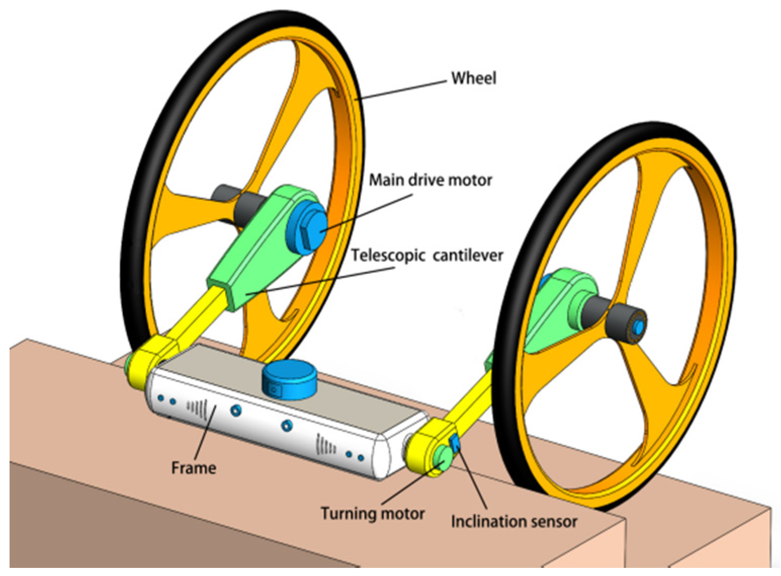
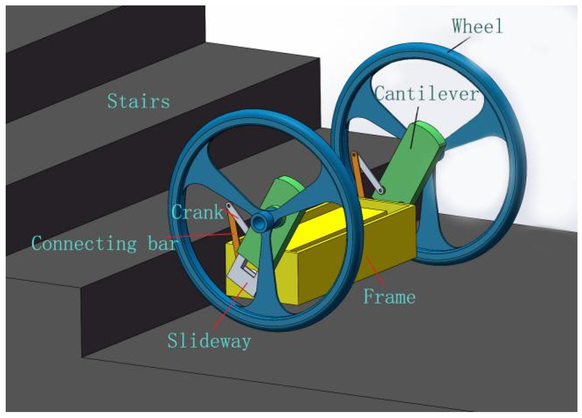
The structural model of the robot is shown in Figure 1. The main structure of the robot is composed of the frame, the left and right symmetrical telescopic cantilever and the wheel. The lower end of the telescopic cantilever is connected to the frame by the motor, which is used to control the attitude of the frame to maintain horizontal stability while the robot is moving. The upper end of the telescopic cantilever is equipped with a main drive motor to drive the wheel movement. The telescopic mechanism is installed inside the telescopic cantilever and forms a translation joint. In summary, the frame, the left and right telescopic cantilever and the left and right wheels constitute the two-wheel “4R+2P” configuration of the two-wheeled climbing stair robot using a combination of four rotation joints and two translation joints.

Figure 1.
The “4R+2P” structure model of the robot.
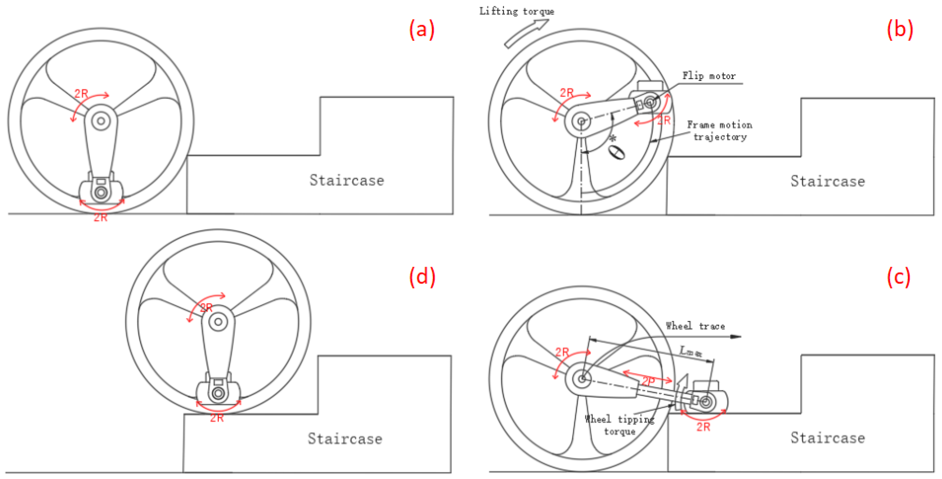
As shown in Figure 2, the stair climbing gait of this “4R+2P” configuration consists of four steps: “approaching, lifting, putting and retraction”, as follows:
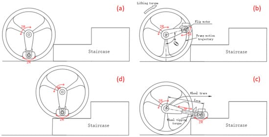
Figure 2.
Gait diagram of climbing stairs by “approaching, lifting, putting and retraction”: (a) the robot approaches stairs; (b) the cantilever lifts the frame; (c) the robot extends its cantilever and sets its frame on the stairs; (d) the robot’s wheels are lifted onto the steps of the frame and the robot enters into an “approaching” gait again.
(1) When the robot runs on the ground and prepares to climb the stairs, the telescopic cantilever retracts its initial position. The robot’s left and right drive motors output a smaller drive torque that causes the robot to move forward and the wheels to lean against the steps while aligning the body of the robot against the positive stairs to complete the first gait: “approaching”;
(2) Since the two wheels of the robot make contact with the stairs and block the rotation under the action of friction force, the output torque of the main drive motor continues to increase, and the telescopic cantilevers are lifted to the preset position under the action of the anti-driving torque to complete the second gait: “lifting”;
(3) In the process of “lifting”, when the inclination sensor installed on the cantilever detects that the vertical inclination θ reaches the preset value θ* after the cantilever lifting, the cantilevers extend forward to the longest position, and the frame is placed on the stairs smoothly to complete the third gait: “putting”;
(4) The main drive motor stops working, and the flip motors installed on both sides of the frame began to work. The left and right wheels of the robot are lifted up the stairs. After the wheels on both sides are lifted up the stairs, the cantilevers retract back to their initial position and complete the fourth gait: “retraction”.
Steps (1) to (4) are repeated such that the robot can completely climb a multilevel set of stairs.
This configuration takes advantage of the characteristics of the robot’s pendulum structure to adjust its own center of gravity and automatically switch the advance state in two different states of flat ground and stair climbing. It decomposes a continuous multistage stair climbing process into a single-stage stair climbing process consisting of four gaits of “approaching, lifting, putting and retraction”. Each step is carried out by the four gaits of “approaching, lifting, putting and retraction”, and after the “retraction” gait of the previous step is completed, the “approaching” gait of the next step is automatically switched to avoid the problems of “slipping, misstep and misplace”, thereby realizing the stable and autonomous stair climbing process of the robot.
3. Motion Modeling and Critical Constraint Condition Analysis
The kinematic model and dynamic model of the robot are established using the D–H method and Lagrange equation method, respectively. The critical states of the robot’s skidding and tilting are analyzed, and the corresponding constraint equations are established.
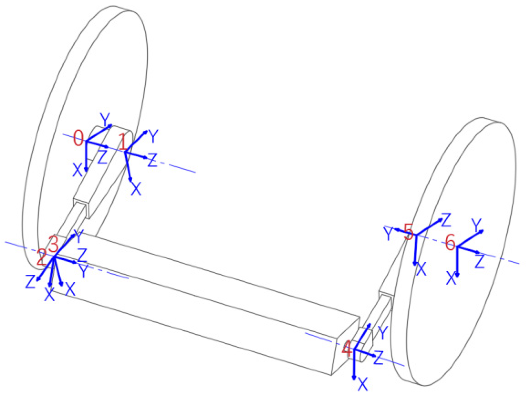
3.1. D–H Modeling
As shown in Figure 3, each link of the robot is abstracted as a set of coordinate systems, 1, 2, 3…6, the three-dimensional space poses a transformation matrix, from coordinate system 0 to coordinate system 5, which is set as the D–H modeling method. The four parameters (i.e., a, α, d, and θ) between the joints of the two-wheeled stair climbing robot are shown in Table 1, and these parameters are used to calculate the gait kinematics of the robot when climbing stairs. The definition and parameters of each joint coordinate system are as follows:
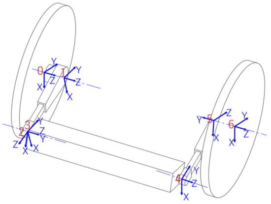
Figure 3.
D–H model diagram of the two-wheeled stair climbing robot with a “4R+2P” pattern.

Table 1.
D–H model parameters.
(1) Since the prerequisite for the robot to climb stairs is the wheel blocking, the unilateral wheel (the right wheel is selected here) is set as the benchmark connecting rod i0;
(2) The rotation joint, i1, is formed between the right wheel and the main drive motor on this side, and the axial direction of the main drive motor is the direction of the Z1 axis;
(3) The translation joint, i2, is formed between the upper and lower telescopic cantilevers on the right side, and the telescopic direction is the direction of the Z2 axis;
(4) The rotation joint, i3, is formed between the right flip motor and the telescopic cantilever on this side, and the axial direction of this flip motor is the direction of Z3 axis;
(5) The rotary joint, i4, is formed between the left flip motor and the frame, and the axial direction of this flip motor is the direction of the Z4 axis;
(6) The moving joint, i5, is formed between the left upper and lower telescopic cantilevers, and its expansion direction is the direction of the Z5 axis;
(7) The rotation joint, i6, is formed between the main drive motor and the telescopic cantilever, and the axis of the main drive motor is the direction of the Z6 axis;
(8) The X-axis is on the common normal between the Z-axis of joint i-1 and joint i, and the direction of the X-axis and Y-axis are determined by the right-handed rule;
(9) ai represents the displacement of joint i relative to the X-axis direction of the joint i-1 coordinate system; αi represents the torsion angle of joint i relative to the X-axis direction of the joint i-1 coordinate system; di represents the displacement of joint i relative to the Z-axis direction of joint i-1 coordinate system; θi represents the torsion angle of joint i relative to the Z-axis direction of the joint i-1 coordinate system.
During the “lifting” gait of the robot when climbing stairs, since the left and right wheels of the robot are not moving, the pose transformation matrix from the left wheel coordinate system 0 to the right wheel coordinate system 6 can be defined as:
Let the left wheel pose matrix be a unit matrix, then the right wheel pose is:
Because the position and orientation of the robot frame can be converted from the position and orientation of the left wheel and the right wheel, respectively, in the process of climbing stairs, so that the position and orientation conversion matrix of the left wheel to the frame and the right wheel to the frame of the robot are equal, the inverse kinematics solution of each joint in the process of climbing stairs can be obtained.
Equations (3) and (4) are the positive kinematics solutions in the “lifting” step of the two-wheeled pendulum stair climbing machine. In the expression, c represents the cos function, and s represents the sin function. For the robot system, the attitude of the frame should always maintain a level; that is, the direction chord matrix of coordinate system 3 is always a unit matrix, and there is:
The inverse kinematics solution of the robot’s “lifting” step can be obtained by combining (3) and (5):
3.2. Dynamic Modeling
During the process when the robot climbs a set of stairs, the degree of freedom of the robot system is set as m, the constraint is complete and the active force is the gravity of each robot joint and each connecting rod. Ignoring the friction in the system motion, the independent generalized coordinates of the robot system are defined, and the system dynamics model is constructed as follows:
Establishment of the Lagrange Equation:
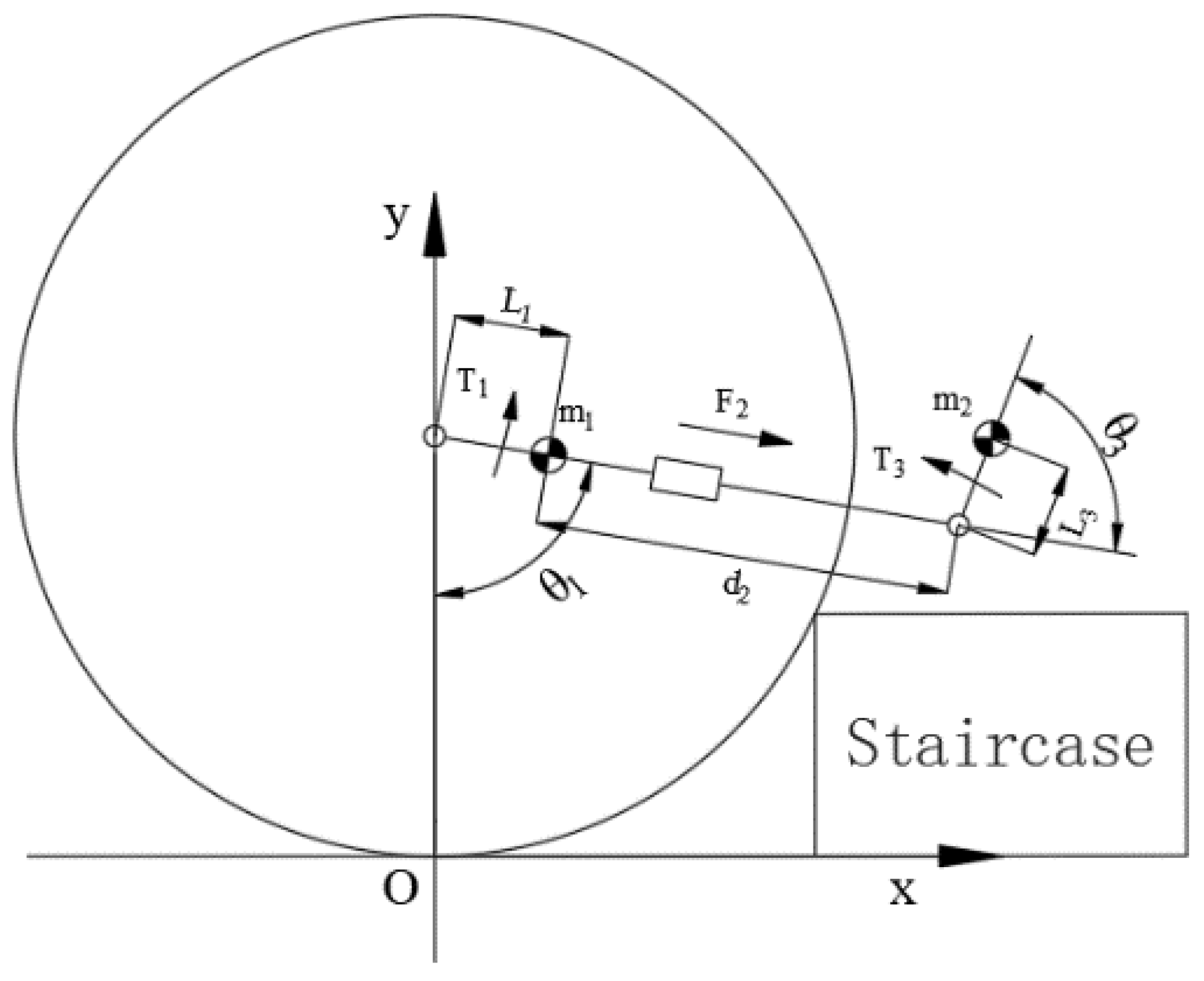
In Equation (8), Qi is the mutually independent generalized force corresponding to the generalized coordinates of the robot system, that is, the driving force for each joint of the robot system to be sought. After both the left and right wheels of the robot make contact with the stairs and block, the left and right telescopic cantilevers synchronously move to lift the frame. Therefore, in the “lifting” gait, the joints and connecting rods of the robot are left and right symmetrical mid-range structures. Ignoring the constraint force of the robot climbing a set of stairs across the wheels’ axis direction, a two-dimensional simplified model of the climbing stair process of the robot is constructed as shown in Figure 4.

Figure 4.
Two-dimensional simplified model of the robot climbing stairs.
The resultant torque, T1, of the main drive motors on both sides, the resultant force, F2, of the telescopic cantilevers on both sides and the resultant torque, T3, of the flip motors on both sides are as follows:
Substituting the mass, length displacement, velocity, acceleration and other parameters of each link in the robot’s system into Equation (9), the driving torque and driving force required by each joint in the climbing stairs process of the robot can be obtained.
3.3. Critical Condition
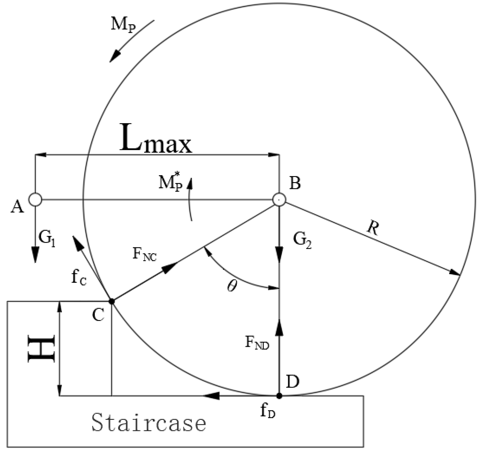
3.3.1. Critical Slip Analysis and Constraint Equation
The prerequisite for the robot to complete the “approaching” action is that the robot remains steady on the stairs, and the wheels do not skid while climbing the stairs. The force analysis of the robot in the “lifting” gait is shown in Figure 5. The weight of the frame is G1, and the weight of the wheel is G2. Mp is the driving torque output by the main drive motor, Mp* is the anti-driving torque borne by the cantilever. The critical condition of wheel sliding is that the contact point C between the wheel and the stairs and the contact point D between the wheel and the ground have reached the critical sliding state. The friction forces of C and D are the maximum static friction force, namely:
which is the maximum static friction coefficient between the wheel and the stairs. In this action, the output torque of the main drive motor of the robot is the largest when and only when the telescopic cantilevers are fully horizontally extended to their longest, and then:

Figure 5.
Force analysis of the robot climbing.
Substituting the above critical conditions and according to the equilibrium conditions:
Insert:
The eccentricity ratio, K, is defined as:
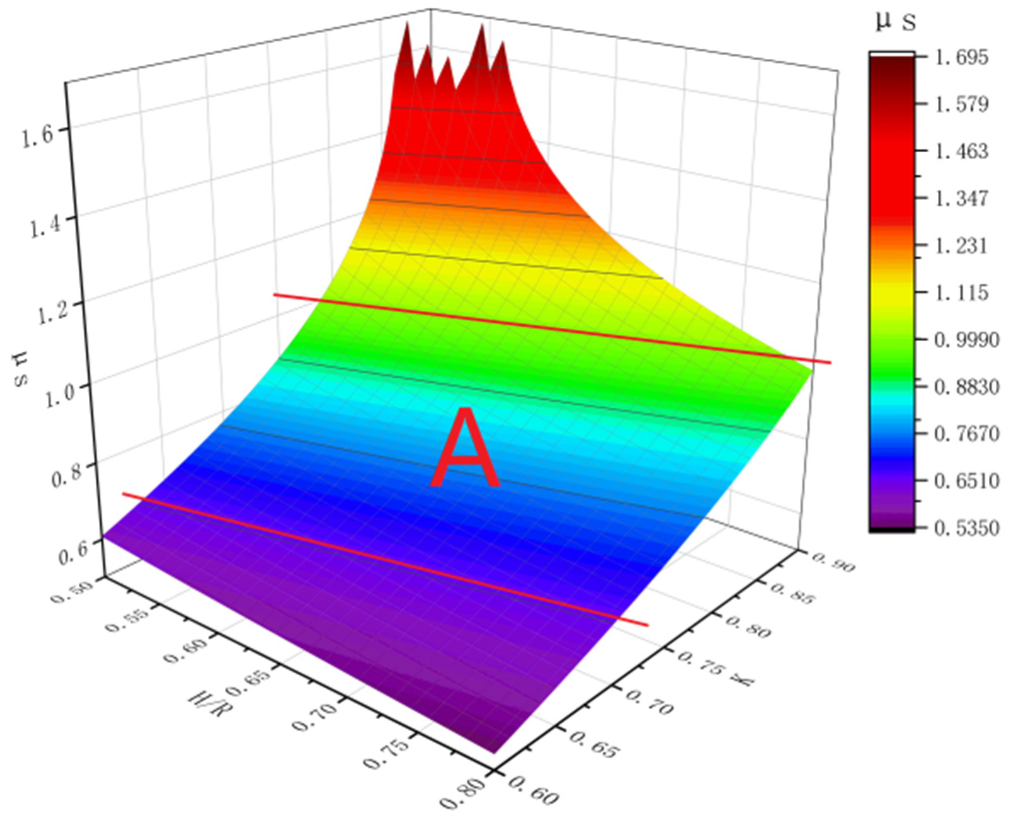
Q = H/R is defined as the maximum height–diameter ratio of stair climbing, and the constraint equation to avoid sliding is:
Through an analysis of the above results, the function image is shown in Figure 6. It can be seen from the figure that appropriately reducing the eccentricity ratio, K, is conducive to reducing the minimum static friction coefficient required by the robot to complete the stair climbing. In addition, a smaller eccentricity can be selected to achieve a larger climbing height–diameter ratio under the condition of a smaller static friction coefficient. The sliding friction coefficient between the common rubber tire and the concrete or dry tile ground is 0.6–1. Considering that the static friction coefficient between the common rubber tire and the ground is greater than the sliding friction coefficient, the interval A in the figure can be used as an optional interval for the design of the structural parameters of the robot.

Figure 6.
Relationship between the minimum static friction coefficient and the maximum climbing stair aspect ratio and eccentricity ratio.
3.3.2. Critical Overturning Analysis and Constraint Equation
In the “retraction” gait, when the flip motor drives the telescopic cantilever and the first overturned wheel connected to it, according to Newton’s third law, the frame will also be subjected to an equal and reverse overturning moment. In this process, the frame can only rely on its own gravity to maintain stability, if the centroid design of the frame is unreasonable, it will be overturned by the overturning torque before the wheel is flipped up to the steps, which will affect the stair climbing process of the robot.
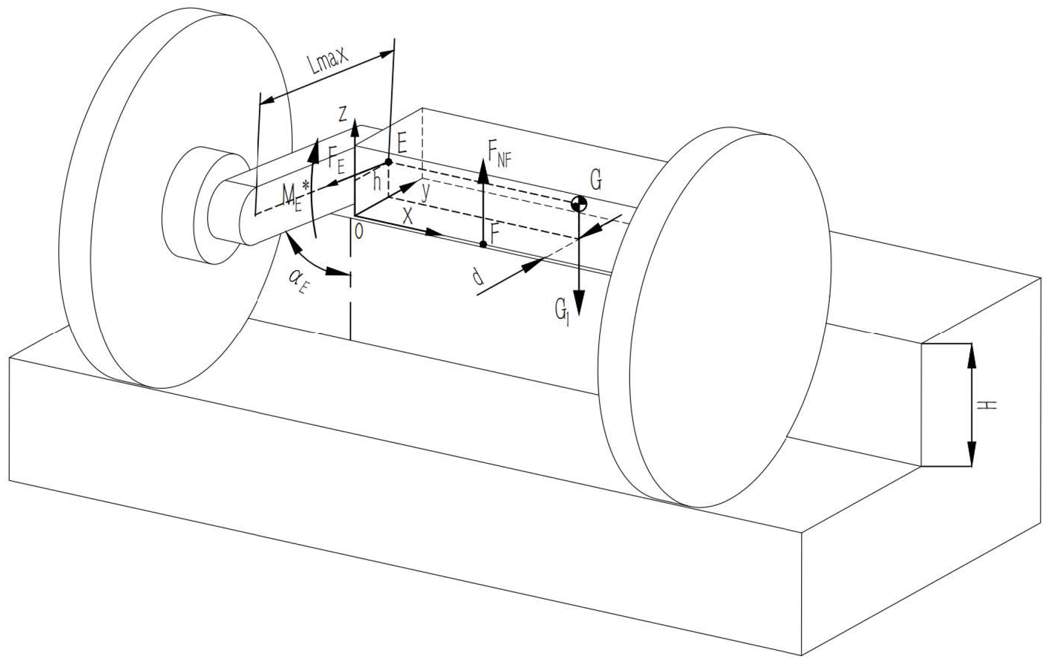
In the mechanical model shown in Figure 7, the frame is regarded as a simple cuboid, and the coordinate system is established with the point closest to the telescopic cantilever at the bottom of the frame as the origin O (i.e., 0, 0 and 0). Moreover, d is the horizontal length from the center point E (i.e., 0, YE and ZE) of the tilting motor to the tail of the frame, and h is the vertical height from the center point E of the tilting motor to the bottom of the frame.
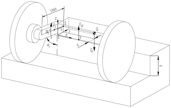
Figure 7.
A simplified model of the mechanics in the case of the robot overturning.
The tensile force of the telescopic cantilever on the frame is FE, the supporting force of stair tread on the frame is FNF, the action point is F (i.e., 0, YF and ZF), the centroid of the frame is G (i.e., xG, yG and zG), and the gravity is G1. The output torque of the motor is ME*. Ignoring the torque in other directions of the frame, the overturning torque, ME, can be simplified as:
The frame can be placed steadily on the stairs, and the tail of the frame should not exceed the stair tread size, namely:
The overturning torque of the frame is greatest at the moment when the one-sided wheel is lifted off the ground by the flip motor. Therefore, the condition to prevent the frame from overturning is the combined force moment (MO)X ≤ 0 in the x-direction of the frame, at which time:
By combining Equations (17) and (18), the constraint equation of avoiding overturning while the robot climbs a set of stairs can be obtained as follows:
The cantilever condition for the robot to climb stairs is:
where LMAX is the length of the cantilever fully extended, R is the radius of the wheel, LB is the width of the stair tread, and p is the distance from the installation position of the flip motor to the vertical plane before the frame.
Since the main drive motor is in a stop working state, when the turning motor turns the wheel to the step, the collision between the wheel and the step will lead to adaptive rotation, which ensures that the wheel will only be turned to the step where the frame is located when it is turned up. Therefore, LMAX only needs to satisfy that the frame can be stably placed on the step without falling or collision with the vertical plane of the next stair.
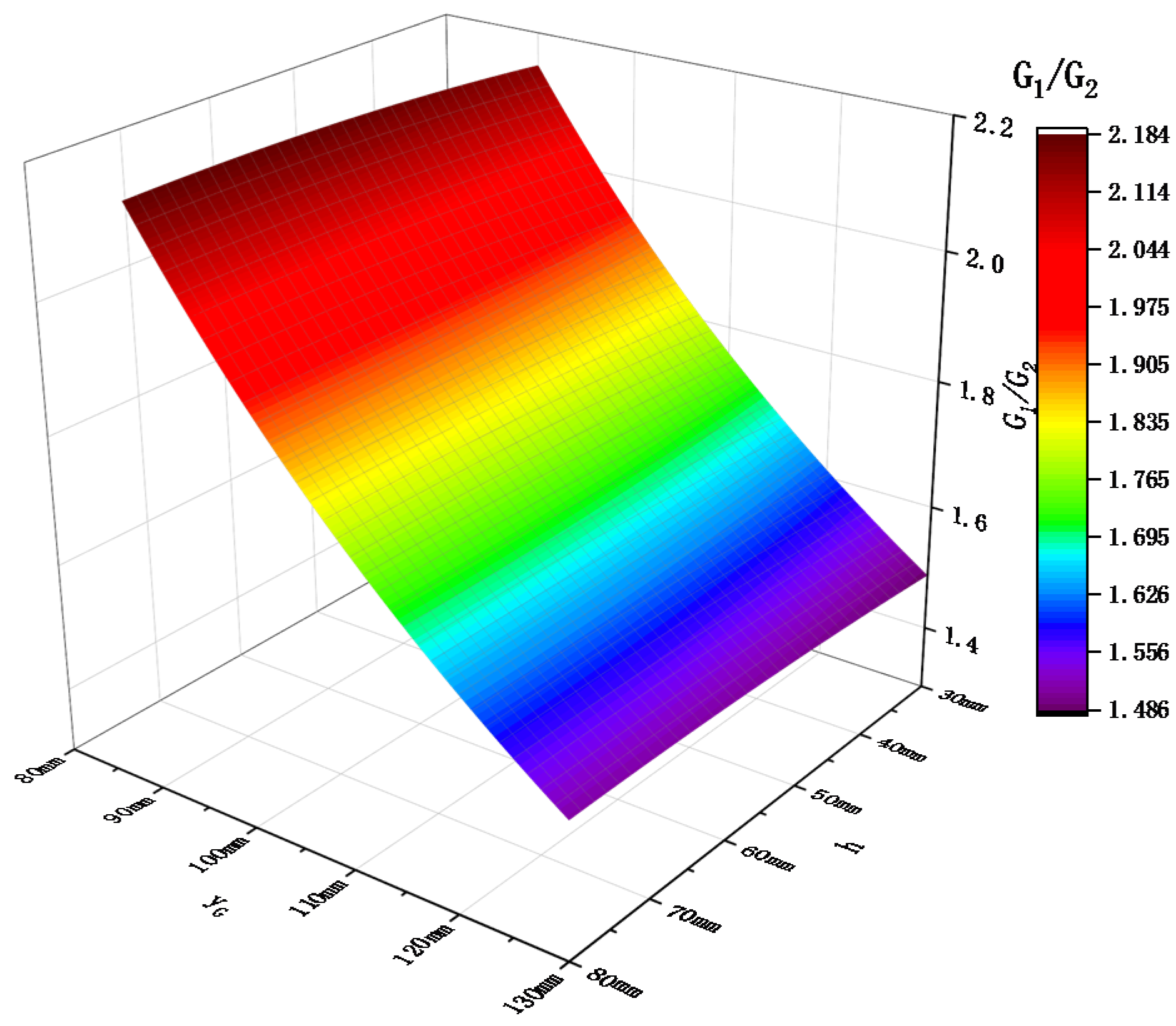
The standard step height of stairs is generally 150~170 mm, and the step width is approximately 300 mm; thus, the maximum step height H = 170 mm was taken. According to the two-wheeled stair climbing robot [23], developed by T. Chen et al. at the University of Auckland, the height-to-diameter ratio was 0.29, and for the two-wheeled inverted pendulum climbing robot [15,24], developed by Takeshi Takaki et al. at Hiroshima University in Japan, the height-to-diameter ratio was 0.51. We expected a height-to-diameter ratio of 0.7. Therefore, the wheel radius, R = (170/0.7)/2 = 243 mm, and the maximum length of telescopic cantilever, LMAX = (300 + 486)/2 = 393 mm, were taken. The above parameters were substituted into Equation (19), and h and yG were taken as independent variables. The function’s image is shown in Figure 8. In order to reduce the peak load torque of the main drive motor in the “lifting” action, it was necessary to reduce the mass of the frame end as much as possible to reduce the eccentricity ratio, K; that is, G1/G2 should be as small as possible. The graph shows that the relative mass ratio G1/G2 of the frame should be reduced under the condition of ensuring the maximum climbing stair height and wheel radius of the robot remain unchanged. In addition to reducing the maximum elongation of the telescopic cantilevers, LMAX, it can also be realized by reducing the installation height of the flip motors, h, or increasing the distance between the frame centroid and the tail of the frame, yG.
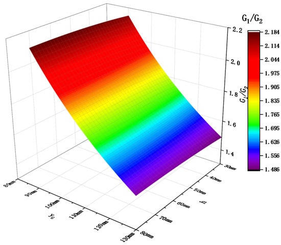
Figure 8.
Relationship between minimum mass distribution requirements and frame centroid yG and installation height h of flip motor.
4. Gait Simulation of Robot Climbing Stairs
Based on the previous modeling analysis, a stair climbing dynamics simulation analysis of the robot was carried out by Solidworks 3D virtual prototype modeling and ADAMS software. The simulation of the virtual prototype was divided into six modules: left and right wheels; left and right telescopic cantilevers; the frame; stairs. The height of the single staircase was 170 mm, and the width was 300 mm. The radius of the wheels were 250 mm, and the maximum cantilever length was 350 mm. The simulation prototype model is shown in Figure 9.

Figure 9.
Simulation model of the prototype.
In the simulation, a speed loop was formed by adjusting the torque output of the main drive through the speed information feedback by the encoder of the main drive motor; the frame fed back the vertical angle information through an angle sensor installed inside it and drove the left and right turning motors to form a vertical loop, such that the frame’s posture remained horizontal. Inclination sensors, installed on the left and right cantilevers, detected the vertical inclination of the cantilever and provided feedback so that the motion control of the left and right main drive motors changed from a speed loop to an angle loop while the wheels were blocked.
4.1. Gait Simulation of Robot “Lifting and Putting” Climbing Stairs
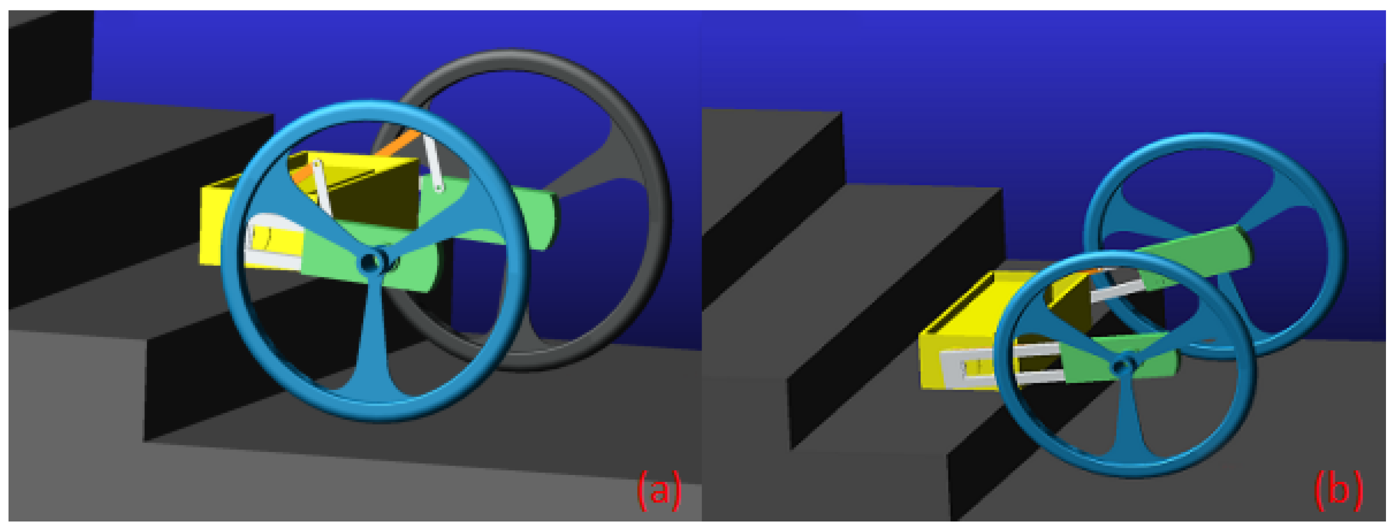
Figure 10 is the process diagram of “approaching, lifting, putting and retraction” in stair climbing gait simulation. When the robot reached the stair steps, the two wheels were blocked, the frame was lifted to a certain height (approximately 100°) by the cantilever and the cantilevers extended to put the frame on the stairs.
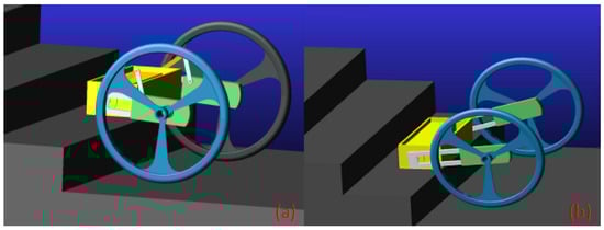
Figure 10.
Gait simulation process diagram of “lifting and putting” during stair climbing: (a) the cantilevers drive the frame lifting due to the main drive motors’ blockage; (b) the frame is lifted to a certain angle and gradually lowered as the eccentricity increases.
When the robot cantilevers are lifted to a position of approximately 100°, the elongation of the telescopic cantilevers will make the eccentricity of the frame increase rapidly, and the response of the control system cannot be corrected in time. The main drive motors still maintain the maximum torque output of the original lifting frame, and the output torque of the original lifting frame of the main drive motors will not be sufficient to “lift” the frame in this state, which eventually makes the frame collide with the stair step surface and makes the stair climbing fail. In order to solve this “lifting” problem, the “excess input TS” is added to the input function of the cantilever angle ring; that is, in the process of cantilever elongation, the target angle value of the cantilever angle ring should also be appropriately increased, so that the control system can increase the torque output of the main drive motor.
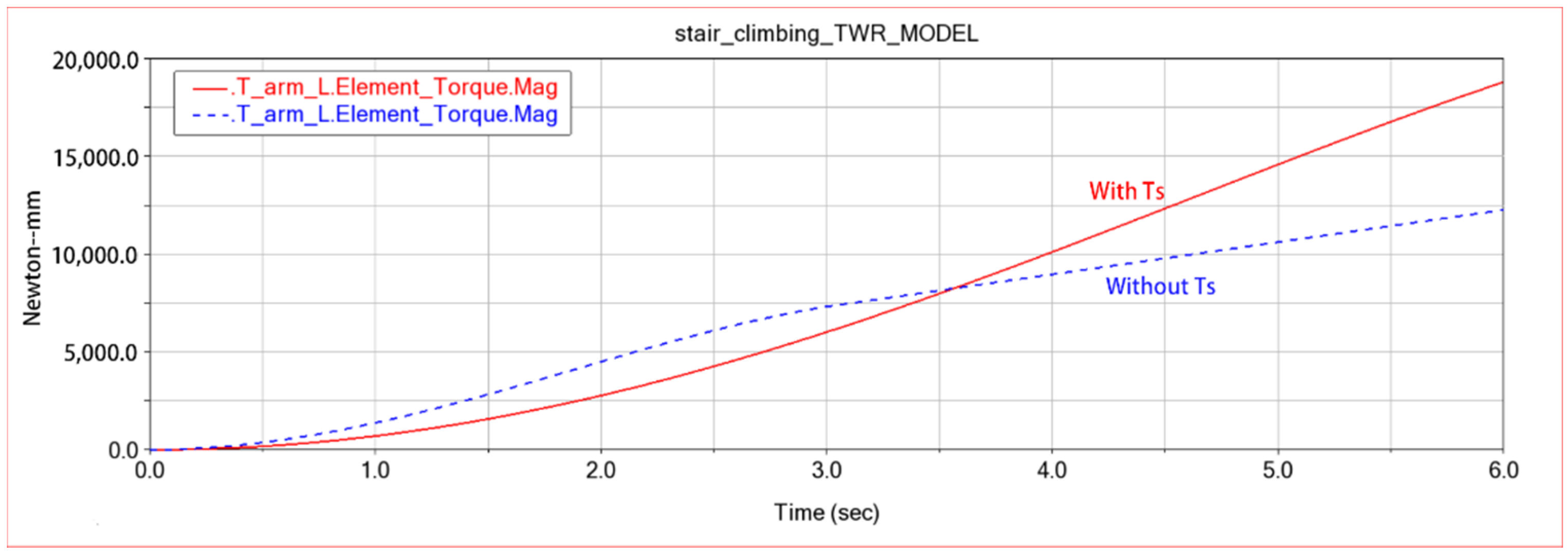
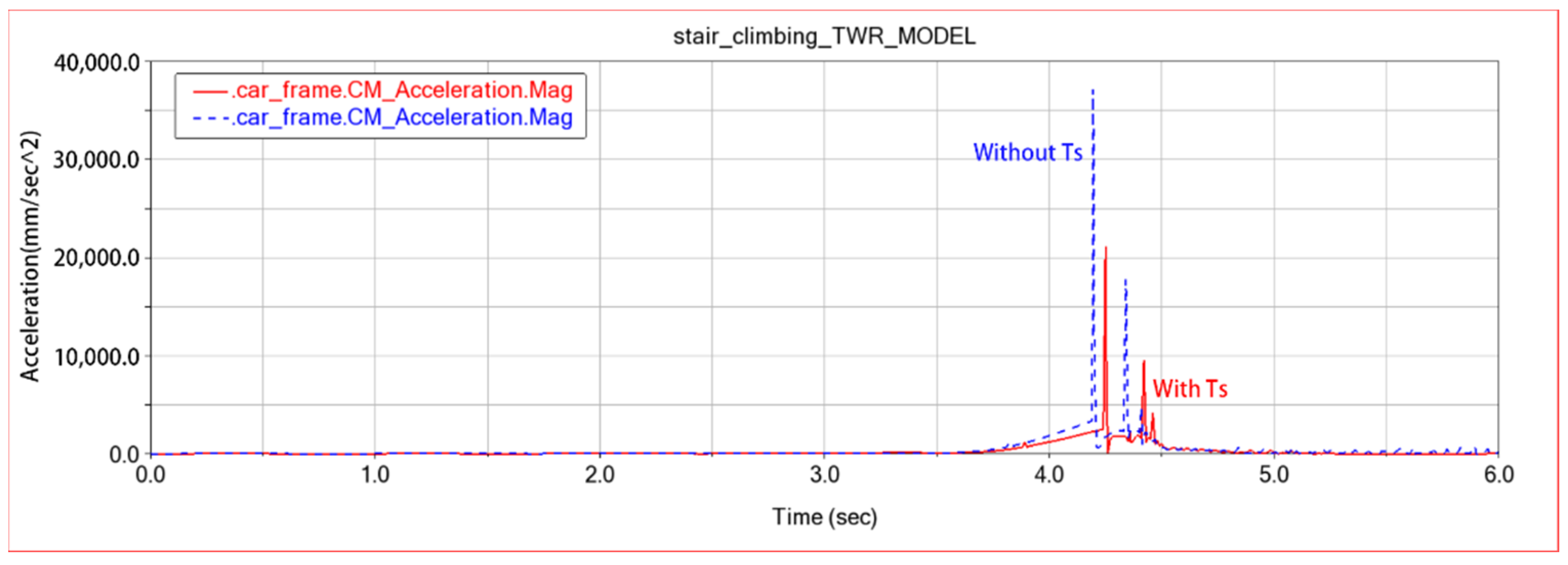
As shown in Figure 11, the blue line represents the output torque of the input function of the cantilever without TS, and the red line represents the output torque of the input function of the cantilever with TS. Obviously, the output torque of the cantilever continues to grow linearly after 3.5 s of cantilever begins to stretch after the input function of the cantilever angle ring is added to the “excess input TS”. Thus, the frame obtains a continuous linear growth of the “lifting” torque during the cantilever elongation to reduce the impact of the frame and the stairs. In Figure 12, the red and blue lines are the frame centroid acceleration with and without Ts. The peak value of the frame centroid acceleration after adding TS is only half before, which achieves the purpose of reducing the impact received by the frame during stairs climbing.
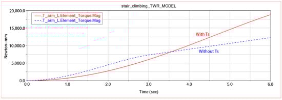
Figure 11.
Output torque of the cantilever angle ring before and after adding TS.
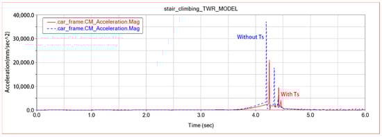
Figure 12.
The acceleration of the frame centroid before and after adding TS.
4.2. Gait Simulation of Robot “Retraction and Approaching” Climbing Stairs
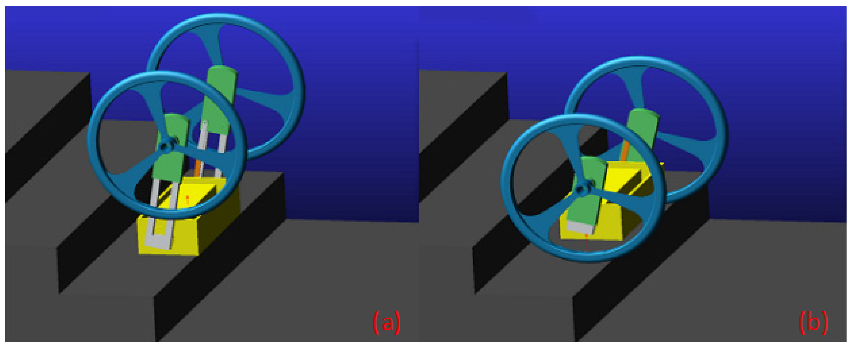
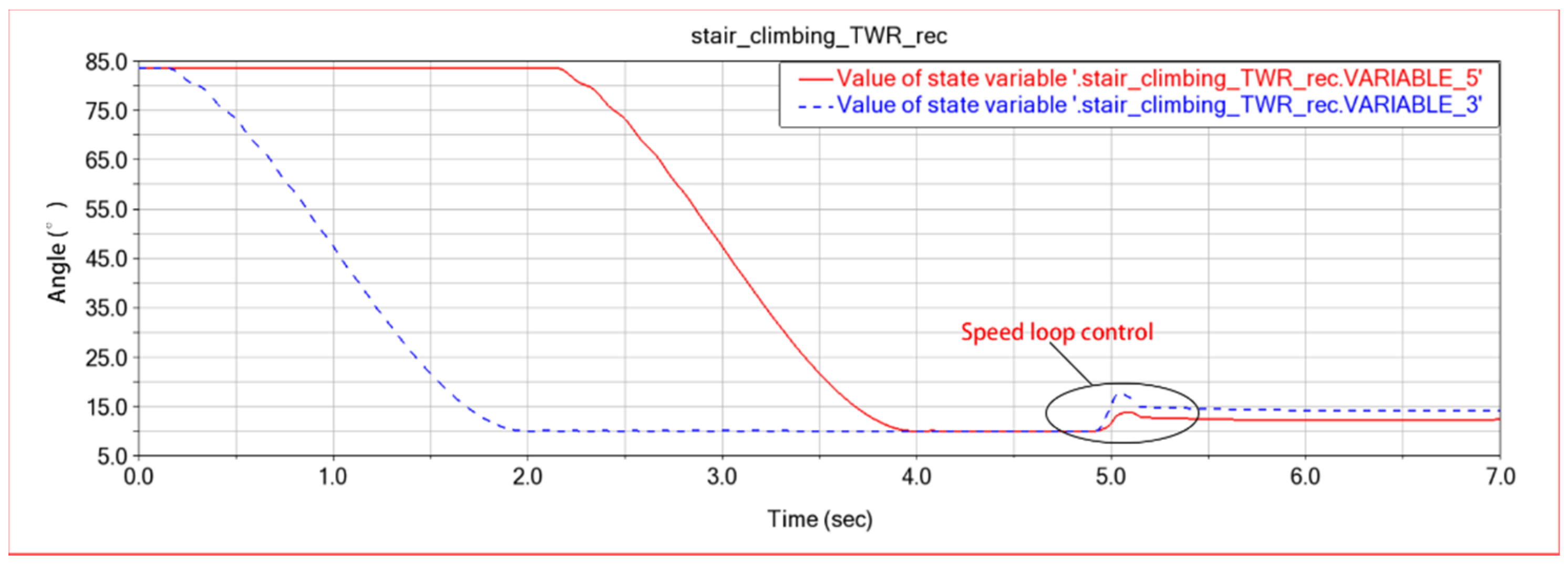
As shown in Figure 13, the main drive motors stop working after the robot frame is placed on the step. The left and right motors drive the left and right cantilevers to flip each side wheel to the step where the frame is located. When the wheel is placed on the ground, the angle sensor on the cantilever reaches the angle threshold of the retractable cantilever, and the retractable cantilever retracts and raises the frame. In 0–2 s, the robot flips the right cantilever to the target position of the next step, and in 2–4 s, the robot flips the left cantilever to the target position of the next step. When the telescopic cantilevers on both sides are in place, the steering gear starts to work and retract the telescopic cantilevers on both sides at the same time. In the fifth second, the bottom of the frame is separated from the bottom of the stair, and the main drive motors on both sides start to enter the speed loop control at the same time to ensure that the robot can maintain a forward movement trend. Turnover motors on both sides of the frame also began to enter the vertical loop control, so that the frame remained upright to complete the reset action until the robot leaned on the back stairs.
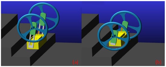
Figure 13.
“Retraction and approaching” stair climbing gait simulation process diagram: (a) the two wheels are turned over to the steps of the frame; (b) the cantilevers drive the wheel back and the robot touches the next stair.
The wheel speed loop control is very important in the “retraction and approaching” gaits. Since the step width of the stair is small, the robot needs to retain a forward force of the body to maintain its own stability in the reset process. As shown in Figure 14, the red line is the vertical inclination change curve of the left telescopic cantilever, and the blue line is the vertical inclination change curve of the right telescopic cantilever. After adding “speed loop control”, the curve shows an upward trend, indicating that the main drive motor maintains a certain forward driving force under the “retraction” gait. If the speed loop control is removed, the robot is prone to fall from the stairs due to uneven ground or torque oscillation generated during the adjustment of body posture.
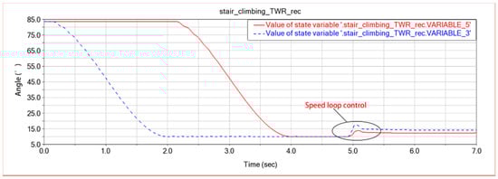
Figure 14.
Variation of the vertical inclination angle of the left and right telescopic cantilevers in the gait of “retraction and approaching” climbing stairs.
5. Climbing Test of Robot Prototype
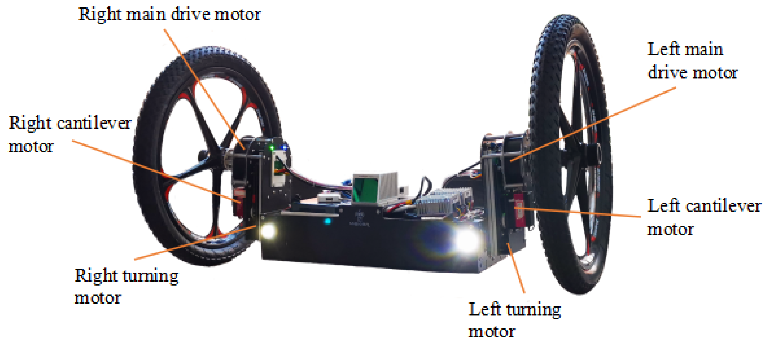
Through the analysis and design of the above two critical constraints, the robot prototype is shown in Figure 15. The main body was composed of left and right wheels, left and right telescopic cantilevers and a frame. The overall size was 500 × 950 × 500 mm. The wheels were 500 × 54 mm mountain bike wheel. The main body and frame of the telescopic cantilever were carbon fiber materials. The weight of the frame was 9.88 kg. The weight of the cantilever and the side wheel was 2.46 kg. The specific parameters and experimental performance of the robot are shown in Table 2.
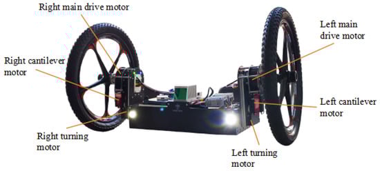
Figure 15.
Prototype model.
Table 2.
Robot parameters and experimental performance.
The telescopic control of the left and right cantilevers of the robot was realized by the steering gear driving the slider-crank mechanism. The cantilevers kept self-locking when moving, and changes in the longest position and the shortest position when climbing stairs. The steering gear had light-weight and large output torque, which can reduce the self-weight of the telescopic cantilever. At the same time, its driving mode was simple and reliable, and its output angle loop control could ensure the accuracy of the longest position and the shortest position of the telescopic cantilevers.
Both the left and right main drive motors and the left and right flip motors of the robot adopted the DC brushless deceleration motor. It adopted the high-performance FOC drive and CAN bus communication mode, and had the functions of position loop, speed loop and motor operation parameter reading. It had the advantages of high control precision, light weight and large output torque.
5.1. Common Stair Climbing Test of Prototype
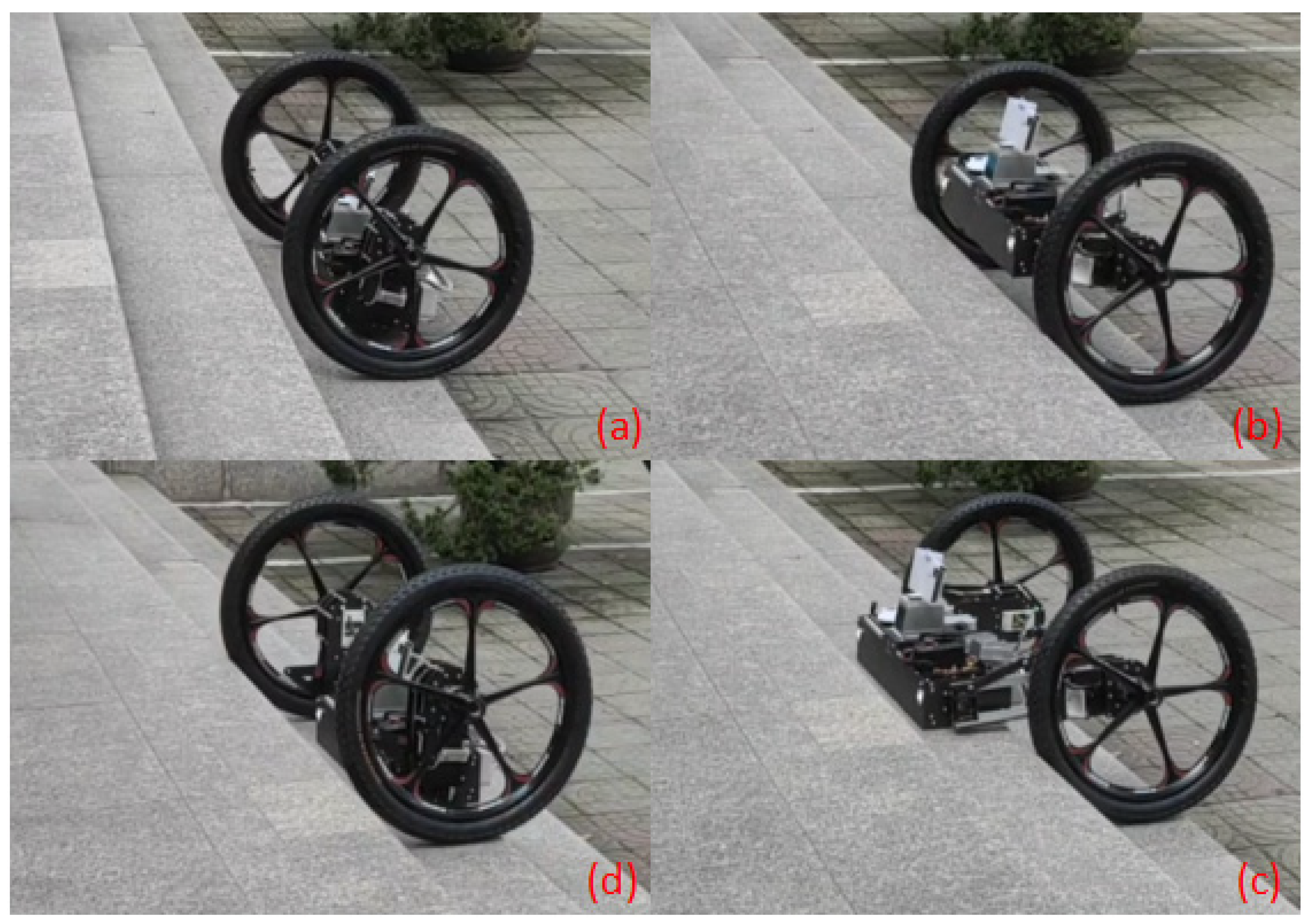
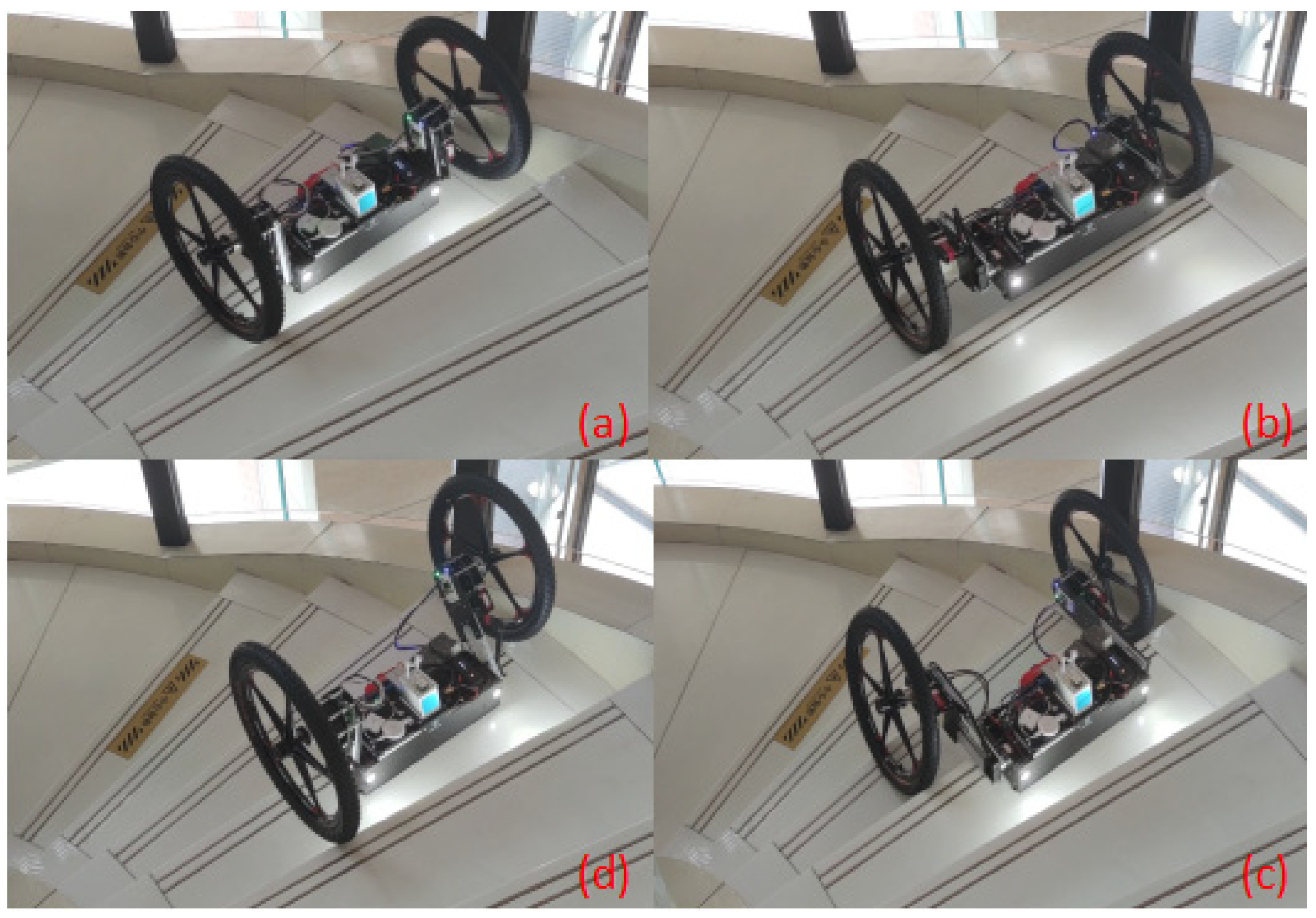
Figure 16 is the experimental process of robot climbing stairs, showing the four gaits of robot climbing stairs. Every time the robot completed the climbing of the first stair, it performed an “approaching” action on the next stair to complete the reset, and finally realized the automatic cycle for climbing stairs. When all the stair steps were climbed, since there is no obstacle in front of the robot, it continued to move forward.
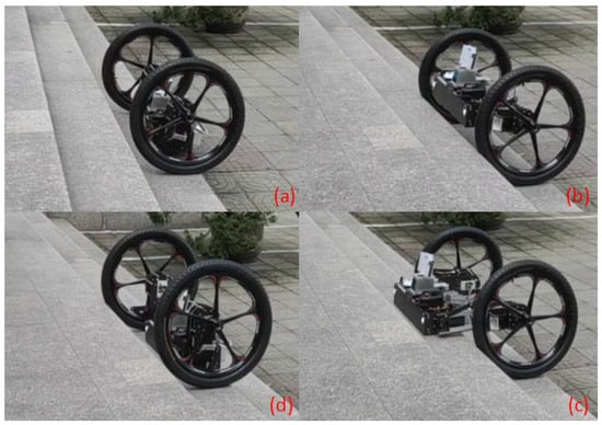
Figure 16.
Robot climbing test process: (a) the robot approaches stairs; (b) the robot’s cantilevers lifts the frame; (c) the robot extends its cantilevers and puts its frame on the stairs; (d) the robot’s wheels are lifted onto the steps of the frame and the robot enters an “approaching” gait again.
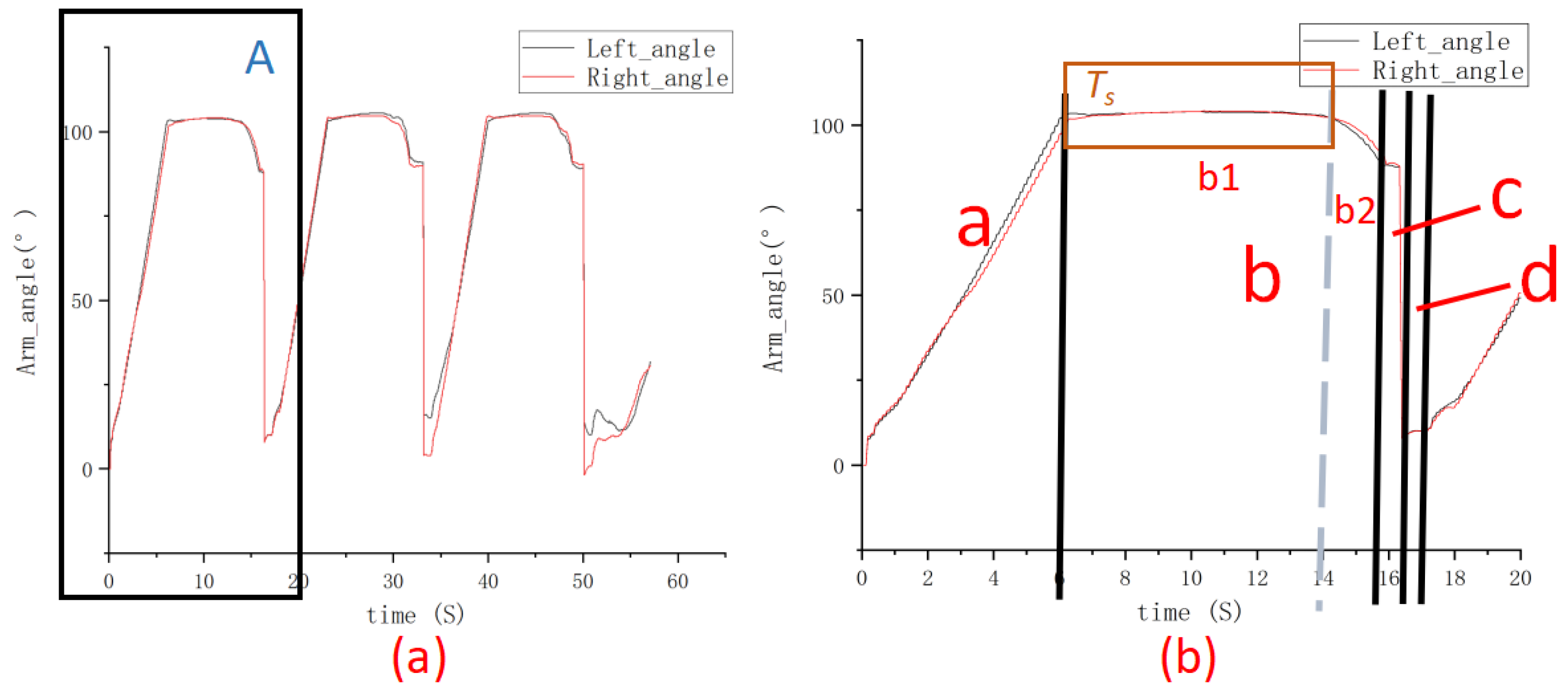
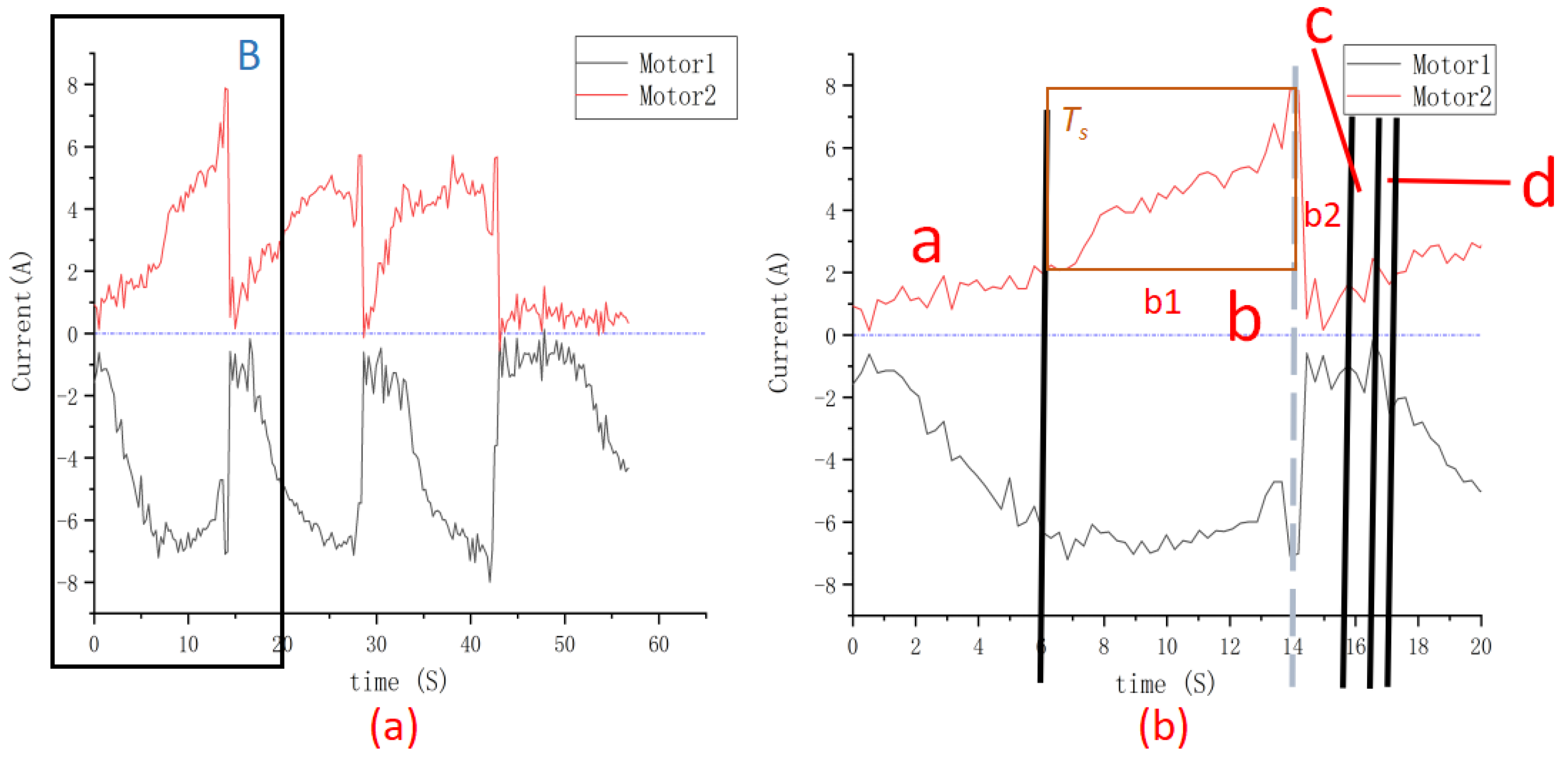
In the prototype climbing experiment, we measured the experimental data of the vertical inclination angle of the left and right cantilevers and the current of the left and right main driving motors in the climbing process of the robot under the condition of two rounds of blocked rotation. The left main driving motor was motor 1, and the right main driving motor was motor 2. The measurement results of each data are shown in Figure 17 and Figure 18. Among them, “a, b, c, and d” were separated by black solid lines, representing the four stages of the robot climbing gait “lifting, putting retraction and approaching”, respectively. The interval b1 and b2 are two subintervals separated by the blue line of the interval b, and b1 denotes the process of cantilever stretching to the longest in the gait released by the robot. b2 Represents the process in which the frame is lowered at the longest cantilever in the gait of the robot.
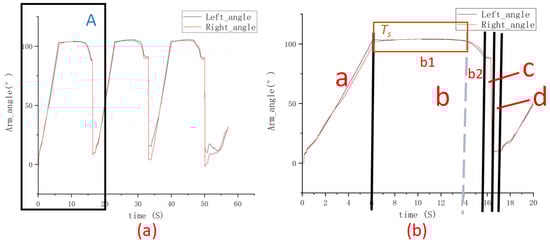
Figure 17.
Cantilever vertical inclination curve of robot stair climbing test: (a) the robot climbs the stairs for 57 s; (b) the amplification diagram of part A in figure (a).
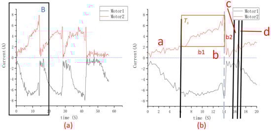
Figure 18.
Current variation curves of the main drive motor for when the robot climbed the stairs: (a) the robot climbs the stairs for 57 s; (b) the amplification diagram of part B in Figure (a).
From Figure 19 and Figure 20, it can be seen that in the interval a, after the wheels were blocked, the current of the main drive motor continued to increase, and the cantilever drove the frame to rise to approximately 100°. At this time, the robot completed the gait of “lifting”. In the range of b1, that is, the control range of TS in the simulation, the cantilever of the robot lifted to the set angle, the cantilever actuator drove the cantilever to slip and elongate and the current of the left and right main drive motor continued to increase, which ensured that the frame did not fall when the cantilever actuator drove the cantilever to elongate. In the b2 interval, the current of the main drive motor decreases rapidly, and at this time, the frame is placed on the step due to the effect of the heavy torque to complete the robot’ s “putting” gait. In the interval c, the cantilever angle decreases rapidly, and the frame is placed on the step. The left and right flip motors at both ends of the frame drove the cantilever to quickly flip the left and right wheels to the step position where the frame was located and shrunk the cantilever, and the frame was reset. At this time, the robot completed the gait of “retraction”. In the interval d, the cantilever always maintained a certain inclination, which ensured that the robot had a forward driving force, so that each robot completed the climbing of the first stair, always maintained the state of forward walking and ensured that the robot did not fall after climbing the stair. Here, corresponding to the “speed loop control” in the simulation, the robot completed the “approaching” gait. Then, the robot continued this cycle gait to climb the stairs.
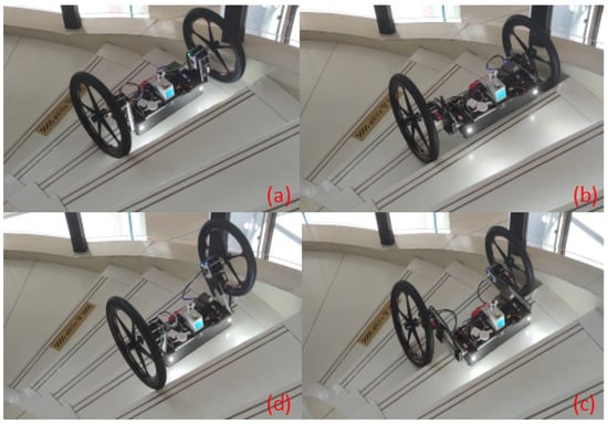
Figure 19.
Spiral stair climbing test of robot: (a) the robot approaches and automatically aligns the rotating stairs; (b) the robot’s cantilevers lifting frame; (c) the robot extends its cantilevers and puts its frame on the stairs; (d) the robot wheels are successively lifted to the steps of the frame, and the robot enters the gait of “approaching” again.
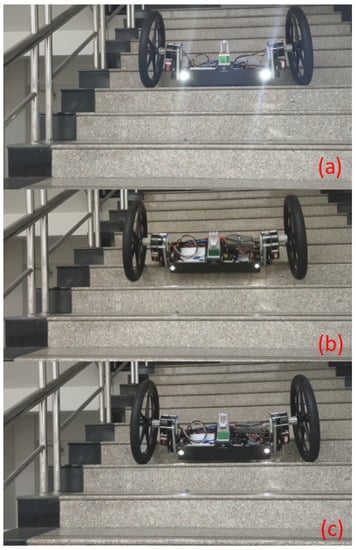
Figure 20.
Experiment of the robot descending stairs: (a) the robot moves forward; (b) the body is tilted and slips down to the steps; (c) after the body is adjusted and stabilized, the robot continues to go downstairs.
5.2. Robot Spiral Stairs Climbing Tests
In the robot climbing experiment, in order to detect the stability of the control system, the navigation system of the robot and the laser radar and other external environment detection sensors were disabled. Only at the beginning, the operator sent out the walking instructions, and the whole process of climbing the stairs was completed by the motion control system of the robot.
As shown in Figure 19, the robot relied on its own preset stair climbing gait to climb rotating stairs. With two rounds of advantages, the robot automatically corrected and corrected the stairs, and then relied on the four-step cycle of climbing the stairs by “approaching, lifting, putting and retraction”. Every time the robot completed climbing the previous level of stairs, it performed the “approaching” action on the next stair to complete the reset, and, finally, realized the automatic cycle of climbing the stairs. If there were no obstacles ahead of the robot, it moved on after climbing all stairs.
5.3. Robot Downstairs Test
Figure 20 shows the test process of the robot autonomously descending stairs. The navigation system lets the robot move slowly along the given direction. When the robot starts to fall down the stairs, the wheels roll to the next stairs first, but the body still maintains its position under the action of inertia, so that the overall centroid of the robot is still located on the current stairs, which ensures the stability of the robot going downstairs. During this process, the robot’s posture will look down first, so that the laser radar can detect whether there are obstacles hindering the robot’s movement in the process of downstairs. When it is confirmed to be safe ahead, the robot will continue to complete the downstairs process.
6. Conclusions
An ADMAS dynamic simulation of the robot was established to verify the feasibility of the designed configuration and its stairs climbing gaits based on modeling and critical constraint analysis. According to the designed configuration, we conducted a stair climbing experiment with the robot prototype. The simulation and experimental results show that the robot provides a new configuration of a two-wheeled, four-gait stair climbing pattern, effectively avoiding the current problems of “slipping, misstep and misplace” and presenting excellent stair climbing performances of “flexible, adaptive and stable” in multiple scenarios. The innovations of this robot are as follows:
1. This robot provides an innovative idea for stably climbing stairs based on the “4P+2R” configuration and a four-step cycle of “approaching, lifting, putting and retraction”;
2. The constraint conditions of slipping and overturning in the process of climbing stairs were established, and the two major problems of the impact of the frame under the “release” gait and the fall of the robot under the “retracted” gait were solved;
3. This new configuration can be applied to various structured stairs including rotating stairs, and it has the advantages of rapid steering in situ, auto-alignment of stairs, nonslipping, nonstepping empty, light structure and up–down stability;
Videos related to the experiment can be found in the Supplementary Materials.
Supplementary Materials
The following supporting information can be downloaded at: https://www.mdpi.com/article/10.3390/machines10080631/s1.
Author Contributions
Conceptualization, L.W.; methodology, H.W.; software, Z.W., W.Y.; validation, G.W. and W.Y.; formal analysis, G.W.; resources, L.W. and H.W.; data curation, G.W.; writing—original draft preparation, G.W., Z.Z. and T.S.; writing—review and editing, L.W. and G.W.; visualization, W.Y.; project administration, L.W.; funding acquisition, L.W., H.W. and Z.W. All authors have read and agreed to the published version of the manuscript.
Funding
This research was funded by the National Natural Science Foundation of China (52175460, 51775154) by Liqun Wu, National Natural Science Foundation of China (11902107) by Associate Hongcheng Wang and the General Research Project of Zhejiang Provincial Department of Education (Y202146872) by Zeen Wang.
Institutional Review Board Statement
Not applicable.
Informed Consent Statement
Not applicable.
Data Availability Statement
Not applicable.
Conflicts of Interest
The authors declare no conflict of interest.
References
- Qin, X.L. Mobile robot walking mechanism. Mech. Eng. 2018, 2, 1002–2333. [Google Scholar]
- Khandelwal, K.; Patel, R.; Shenoy, A.; Farooquee, S.; George, G. Application of stair climbing robot. In Proceedings of the International Conference on Technologies for Sustainable Development (ICTSD), Mumbai, India, 4–6 February 2015. [Google Scholar]
- Bruzzone, L.; Baggetta, M.; Nodehi, S.E.; Bilancia, P.; Fanghella, P. Functional Design of a Hybrid Leg-Wheel-Track Ground Mobile Robot. Machines 2021, 9, 10. [Google Scholar] [CrossRef]
- Liu, C.; Tan, X.; Yao, Y.; Fu, Z. Design and Analysis of a Novel Deformable Wheel-legged Robot. J. Mech. Eng. 2022, 58, 65–74. [Google Scholar]
- Alexander, J.C.; Maddocks, J.H. On the Kinematics of Wheeled Mobile Robots. Int. J. Robot. Res. 2016, 8, 15–27. [Google Scholar] [CrossRef]
- Chakraborty, N.; Ghosal, A. Kinematics of wheeled mobile robots on uneven terrain. Mech. Mach. Theory 2004, 39, 1273–1287. [Google Scholar] [CrossRef]
- Zhongyu, W.H.S.M.W.; Li, Z.C.L. Novel Flexible Foot System for Humanoid Robot Adaptable to Uneven Ground. Chin. J. Mech. Eng. 2010, 23, 725. [Google Scholar]
- Biswal, P.; Mohanty, P.K. Development of quadruped walking robots: A review. Ain Shams Eng. J. 2021, 12, 2017–2031. [Google Scholar] [CrossRef]
- Kim, H.; Kim, D.; Yang, H.; Lee, K.; Seo, K.; Chang, D.; Kim, J. Development of a wall-climbing robot using a tracked wheel mechanism. J. Mech. Sci. Technol. 2008, 22, 1490–1498. [Google Scholar] [CrossRef]
- Chen, H.; Li, T.; Xu, J. Stair climbing performance of articulated tracked robot. Electron. Mech. Eng. 2006, 2, 60–63. [Google Scholar]
- Zhai, G.; Ren, C.; Meng, L. Design of planetary-wheeled mobile robot and analysis of obstacles crossing ability. Int. J. Robot. Autom. 2020, 35. [Google Scholar] [CrossRef]
- Fang, L.; Lu, T.; He, W.; Yuan, K. Dynamic and tip-over stability analysis of a planetary wheeled stair-climbing wheelchair. In Proceedings of the 2012 IEEE International Conference on Mechatronics and Automation, Chengdu, China, 5–8 August 2012; pp. 2541–2546. [Google Scholar]
- Takaki, T.; Aoyama, T.; Ishii, I. Development of Inverted Pendulum Robot Capable of Climbing Stairs Using Planetary Wheel Mechanism. In Proceedings of the IEEE International Conference on Robotics & Automation, Karlsruhe, Germany, 6–10 May 2013; IEEE: Piscataway, NJ, USA, 2013. [Google Scholar]
- Liu, J. From Big Dog to Spot Mini: History of Boston Dynamic Quadruped Robot Evolution. Robot. Ind. 2018, 2, 109–116. [Google Scholar]
- Seok, S.; Wang, A.; Chuah, M.Y.; Hyun, D.J.; Lee, J.; Otten, D.M.; Kim, S. Design Principles for Energy-Efficient Legged Locomotion and Implementation on the MIT Cheetah Robot. IEEE/ASME Trans. Mechatron. 2015, 20, 1117–1129. [Google Scholar] [CrossRef] [Green Version]
- Bosworth, W.; Kim, S.; Hogan, N. The MIT super mini cheetah: A small, low-cost quadrupedal robot for dynamic locomotion. In Proceedings of the 2015 IEEE International Symposium on Safety, Security, and Rescue Robotics (SSRR), West Lafayette, IN, USA, 18–20 October 2015; pp. 1–8. [Google Scholar]
- Hutter, M.; Gehring, C.; Jud, D.; Lauber, A.; Bellicoso, C.D.; Tsounis, V.; Hwangbo, J.; Bodie, K.; Fankhauser, P.; Bloesch, M.; et al. Anymal—A Highly Mobile and Dynamic Quadrupedal Robot. In Proceedings of the 2016 IEEE/RSJ International Conference on Intelligent Robots and Systems (IROS), Daejeon, Korea, 9–14 October 2016; pp. 38–44. [Google Scholar]
- Kau, N.; Schultz, A.; Ferrante, N.; Slade, P. Stanford Doggo: An Open-Source, Quasi-Direct-Drive Quadruped. In Proceedings of the 2019 International Conference on Robotics and Automation (ICRA), Montreal, QC, Canada, 20–24 May 2019. [Google Scholar]
- Tsitsimpelis, L.; Taylor, C.J.; Lennox, B.; Joyce, M.J. A review of ground-based robotic systems for the characterization of nuclear environments. Prog. Nucl. Energy 2019, 111, 109–124. [Google Scholar] [CrossRef]
- Arai, M.; Tanaka, Y.; Hirose, S.; Kuwahara, H.; Tsukui, S. Development of ‘souryu-IV’ and ‘souryu-V’: Serially Connected Crawler Vehicles for in-Rubble Searching Operations. J. Field Robot. 2008, 25, 31–65. [Google Scholar] [CrossRef]
- Kim, D.; Hong, H.; Kim, H.S.; Kim, J. Optimal design and kinetic analysis of a stair-climbing mobile robot with rockerbogie mechanism. Mech. Mach. Theory 2012, 50, 90–108. [Google Scholar] [CrossRef]
- Zhang, S.; Xing, Y.; Hu, Y. Robotic wheel-foot compound obstacle-crossing gait planning method under obstacle terrain. Navig. Control 2019, 18, 62–70. [Google Scholar]
- Chen, T.; Hazelwood, P.; Stol, K. Step Ascent Modelling of a Two-Wheeled Robot. In Proceedings of the 2012 19th International Conference on Mechatronics and Machine Vision in Practice (M2VIP), Auckland, New Zealand, 28–30 November 2012; pp. 310–315. [Google Scholar]
- Wardana, A.A.; Takaki, T.; Aoyama, T.; Ishii, I. Dynamic modeling and step-climbing analysis of a two-wheeled stair-climbing inverted pendulum robot. Adv. Robot. 2019, 34, 313–327. [Google Scholar] [CrossRef]

Publisher’s Note: MDPI stays neutral with regard to jurisdictional claims in published maps and institutional affiliations. |
© 2022 by the authors. Licensee MDPI, Basel, Switzerland. This article is an open access article distributed under the terms and conditions of the Creative Commons Attribution (CC BY) license (https://creativecommons.org/licenses/by/4.0/).