Article

An Improved Permanent Magnet Synchronous Motor Rotor Position Observer Design Based on Error Harmonic Elimination

1
College of Engineering and Technology, Tianjin Agricultural University, Tianjin 300384, China
2
School of Control and Mechanical Engineering, Tianjin Chengjian University, Tianjin 300384, China
3
Tianjin Internal Combustion Engine Research Institute, Tianjin 300072, China
*
Author to whom correspondence should be addressed.
Machines 2022, 10(8), 633; https://doi.org/10.3390/machines10080633
Submission received: 29 June 2022 / Revised: 25 July 2022 / Accepted: 27 July 2022 / Published: 30 July 2022
(This article belongs to the Special Issue Advances in Electrical Machines, Drives and Vehicles)

Abstract

:
An improved rotor position observer based on sliding mode control was proposed to eliminate estimation error and harmonic ripples for PMSM sensorless control. A multi-proportional resonant filter was designed instead of a low-pass filter to filter out the specific harmonics of back EMF. The improved filter can solve the phase delay problem caused by a low-pass filter, eliminate the rotor angle compensator, simplify the system structure, and effectively suppress the system chattering. Then, a fractional normalized phase-locked loop was adopted to calculate the speed and rotor position, further eliminating the influence of noise. Compared with the traditional sliding mode control and the improved sliding mode control, the improved sliding mode observer can effectively suppress the back EMF chattering and reduce the speed estimation error. The correctness and effectiveness of the proposed improved sliding mode observer were verified through the simulation model and experimental platform of PMSM sensorless control.

1. Introduction

PMSMs are used in various industries such as industrial robots and machine tools [1,2]. The advantages of PMSM include high efficiency, compactness, high torque-to-inertia ratio, fast dynamic response, and simple modeling and control [3]. Due to these advantages, PMSMs are well suited for high-performance servo drives [4,5].
In order to achieve field-oriented control, in any case, the exact position of the rotor is required. To achieve this, a position/speed sensor mounted on the shaft is usually used. This sensor is usually a decoder or encoder and is connected from the machine to the circuit. However, the high cost of this sensor greatly affects the choice of control algorithm. Mounting physical sensors on shafts also has limitations and is susceptible to noise and the environment surrounding the industry. Due to the limitations and advancements of high-speed processors, researchers have found the idea of proposing and implementing a sensorless algorithm to reduce cost and hardware dependencies that can be applied to machines of any size and any type of environment [6].
Sensorless control technology can be divided into two categories. One is based on back EMF or flux linkage method; the other is based on salient polarity. Among them, the first kind often adopts the SMO method [7,8,9,10,11], the model reference adaptive method (MRAS) [12,13], the Kalman filter (EKF) [14,15], etc. These methods propose a state observer by measuring voltage and current, they estimate the back electromotive force (EMF) by relying on the machine model, and finally they obtain the position and speed information of the rotor. However, these methods have an obvious disadvantage: they lack the information of the motor at rest or at low-speed conditions, resulting in it only being suitable for the application of medium and high-speed motor control. In addition, this method is usually sensitive to motor torque ripple and system noise [16]. The second method is to inject high-frequency signal into the stator winding and obtain the rotor position from the output current. This method is suitable for the motor starting and low speed operation, and some examples are the rotating high frequency injection method, the pulsating high frequency voltage injection method, and the high-frequency square wave injection method. However, the injected signal will produce a harmonic current, which will increase loss and cause torque oscillation. Among these methods, the SMO method is widely used in sensorless motor control of permanent magnet synchronous motors due to its simple algorithm, robustness to interference, and good dynamic performance [17].
However, due to the influence of mechanical tolerances, temperature changes, inverter nonlinearity, and other factors, there are a large estimation errors in the back EMF, and there are harmonic components in the estimated back EMF. The error further increases the calculation error of the speed and rotor position, which affects the system stability and increases the system loss. Traditional SMO usually uses LPF to filter out high-order harmonics in the back EMF. However, while using LPF to filter out harmonics, LPF also brings a phase delay. In order to eliminate system errors, it is usually necessary to perform angle compensation according to the rotor angular velocity. To solve the above problems [18], it is proposed to calculate the disturbance voltage caused by inverter nonlinearity through a special back EMF function and magnetic flux increment and then add it to the current loop as a feedforward component. However, due to the current sampling delay problem, this method is difficult to implement in practice. Reference [19] used an adaptive filter that can track the frequency component changes caused by changes in working conditions online. The LMS adaptive filter can use an adaptive step size, which can improve the harmonic detection accuracy and system convergence speed. The change had a great impact on the performance of the LMS, and the robustness was not strong. The effect of space harmonics was also considered in [20,21].
The fifth and seventh harmonics are usually present in the back EMF estimation results, and the sixth harmonic can be generated in the position and velocity estimation. Therefore, an adaptive notch filter (ANF) was proposed in the literature [20,21,22,23], which is a second-order generalized integrator (SOGI) to filter out the harmonics in the estimated back EMF that achieves a high-precision rotor position and rotor angular velocity calculation.
The improvement measures of the existing sliding mode observer sensorless control methods have their own characteristics. Some high-performance filtering methods are mainly used to reduce the interference of the system, and preliminary research results have been achieved. In order to eliminate the phase delay caused by the traditional filter, to simplify the filter structure, and to improve the accuracy of rotor position estimation, an improved SMO was designed that uses the multi proportional resonant filter (MPF) instead of the traditional filter to filter out the specific harmonics in the estimated back EMF and eliminate the phase delay caused by the low-pass filter. At the same time, the phase-locked loop technology for speed and rotor position calculation was improved, and the fractional order normalized phase-locked loop (FN-PLL) was designed to simplify the system structure and eliminate the phase compensator. Finally, the simulation and experimental analysis of traditional SMO and improved SMO were carried out, and the effects of rotor speed and position estimation under different methods were compared, which verified the feasibility and effectiveness of the control strategy.

2. Mathematical Model of PMSM

In this paper, a surface mounted permanent magnet synchronous motor was selected for analysis. The space vector diagram of the PMSM is shown in Figure 1.
The voltage model of a PMSM motor in the d-q frame can be expressed as
[ u d u q ] = [ R + L   L p ω e L p ω e       R + L s ] [ i d i q ] + [ 0 ψ p ω e ]
where ud and uq are the stator voltages, id and iq are the stator currents, p is the number of pole pairs, R and L are the equivalent resistance and inductance of the stator winding, ωe is the electrical angular velocity of the rotor, and ψ is the permanent magnet flux linkage.
Then, the voltage model of the surface mounted PMSM in the α-β coordinate can be expressed as
[ u α u β ] = L d d t [ i α i β ] + R [ i α i β ] + [ e α e β ]
[ e α e β ] = ψ ω e [ sin θ e cos θ e ]
where uα and uβ are the stator voltage in the α-β coordinate, eα and eβ are the back EMF, iβ and iβ are the stator current, and θe is the electrical angle of the rotor position.
The mechanical equation of the PMSM is as follows:
( F + J s ) ω e = 1.5 P ψ i q T e   T L
where F is the dynamic friction coefficient, J is the moment of inertia, Te and TL are the electromagnetic torque and the load torque, respectively, and p is the pole pairs.

3. Rotor Position Observer with Traditional SMO

Firstly, the sliding mode function Sn is defined as follows:
s n = [ s α s β ] = [ i ^ α i α i ^ β i β ]
According to Equation (2), the state function of PMSM is expressed as:
d d t [ i α i β ] = 1 L [ R                 0 0                 R ] [ i α i β ] + 1 L [ u α e α u β e β ]
Then, the SMO model of PMSM can be expressed as:
d d t [ i ^ α i ^ β ] = R L [ i ^ α i ^ β ] + 1 L [ u α u β ] 1 L   [ z α z β ]
where “^” represents the estimate value, zα and zβ are the sliding mode control functions; when the sliding mode motion occurs, zα and zβ contain the rotor position information, and the sliding mode control function can be expressed by the Sign (x) function as:
[ z α z β ] = k [ Sign ( i ^ α i α ) Sign ( i ^ β i β ) ]  
The k is the switching gain of SMO and k > {|Eα|, |Eβ|}, where Sign (x) can be expressed as:
Sign ( x ) = { 1 ,                         x > 0 0   ,                       x = 0 1 ,                   x < 0
From (6) and (7), the current estimation error is given by:
d d t [ s α s β ] = R L [ s α s β ] + 1 L [ e α z α e β z β ]
When the state variables reach the sliding surface, there is:
[ s α s β ] = [ i ^ α i α i ^ β i β ] = 0  
The zα and zβ can be obtained by (11) and (3), which can be expressed as:
[ e α e β ] [ z α z β ] = ψ ω e [ sin θ e cos θ e ]
It can be seen from (12) that the sliding mode function contains back EMF information, so the speed and rotor position can be calculated. Since the back EMF contains chattering, a low-pass filter (LPF) is usually used to filter out high-order harmonics.
{ e ^ α = LPF ( z α ) = ω c s + ω c z α e ^ β = LPF ( z β ) = ω c s + ω c z β
where ωc is the cut-off frequency of the LPF. The estimated electric angle θ ^ and electric angular speed ω ^ e are, respectively, expressed as
θ ^ = arctan ( e ^ α / e ^ β )
ω ^ e = E ^ α 2 + E ^ β 2 ψ
Since the use of the LPF will cause phase delay, the calculated rotor position needs to be compensated, and the compensation angle is
Δ θ = arctan ( ω ^ e / ω c )
The rotor position estimated by the slide mode observer can be finally expressed as
θ ^ e = θ ^ + Δ θ
Figure 2 is the block diagram of the traditional slide mode observer.

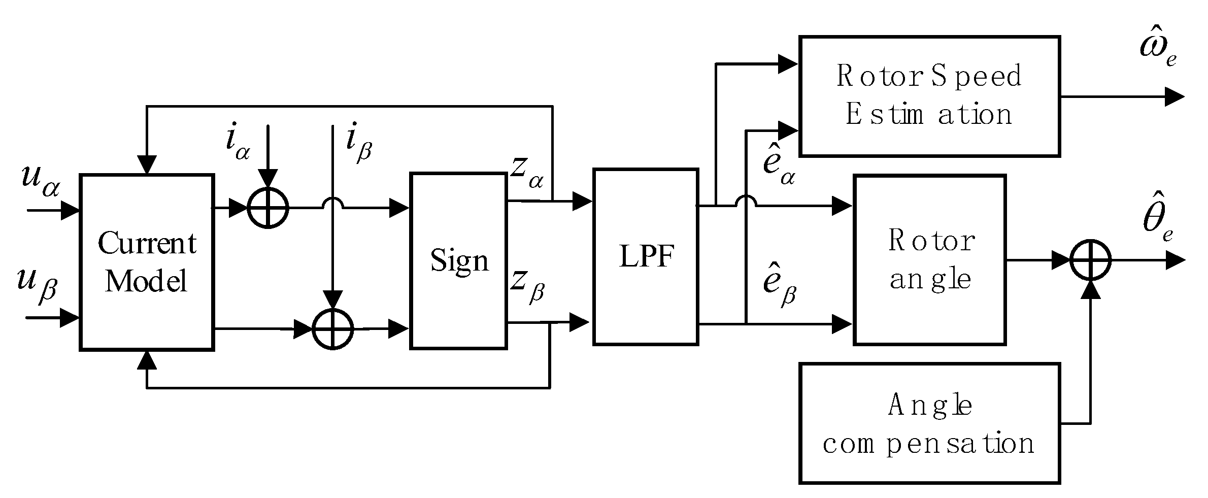
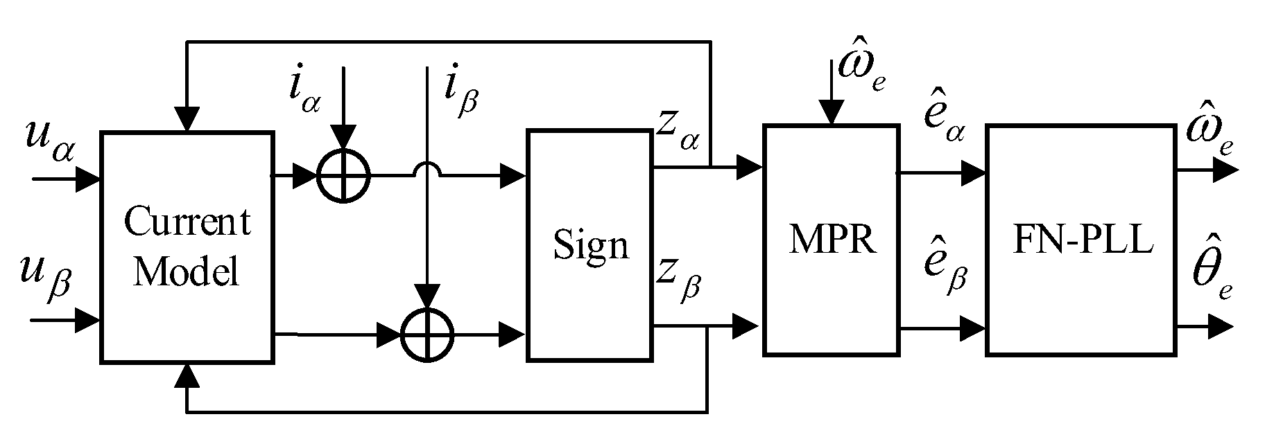
4. Improved Rotor Position Observer

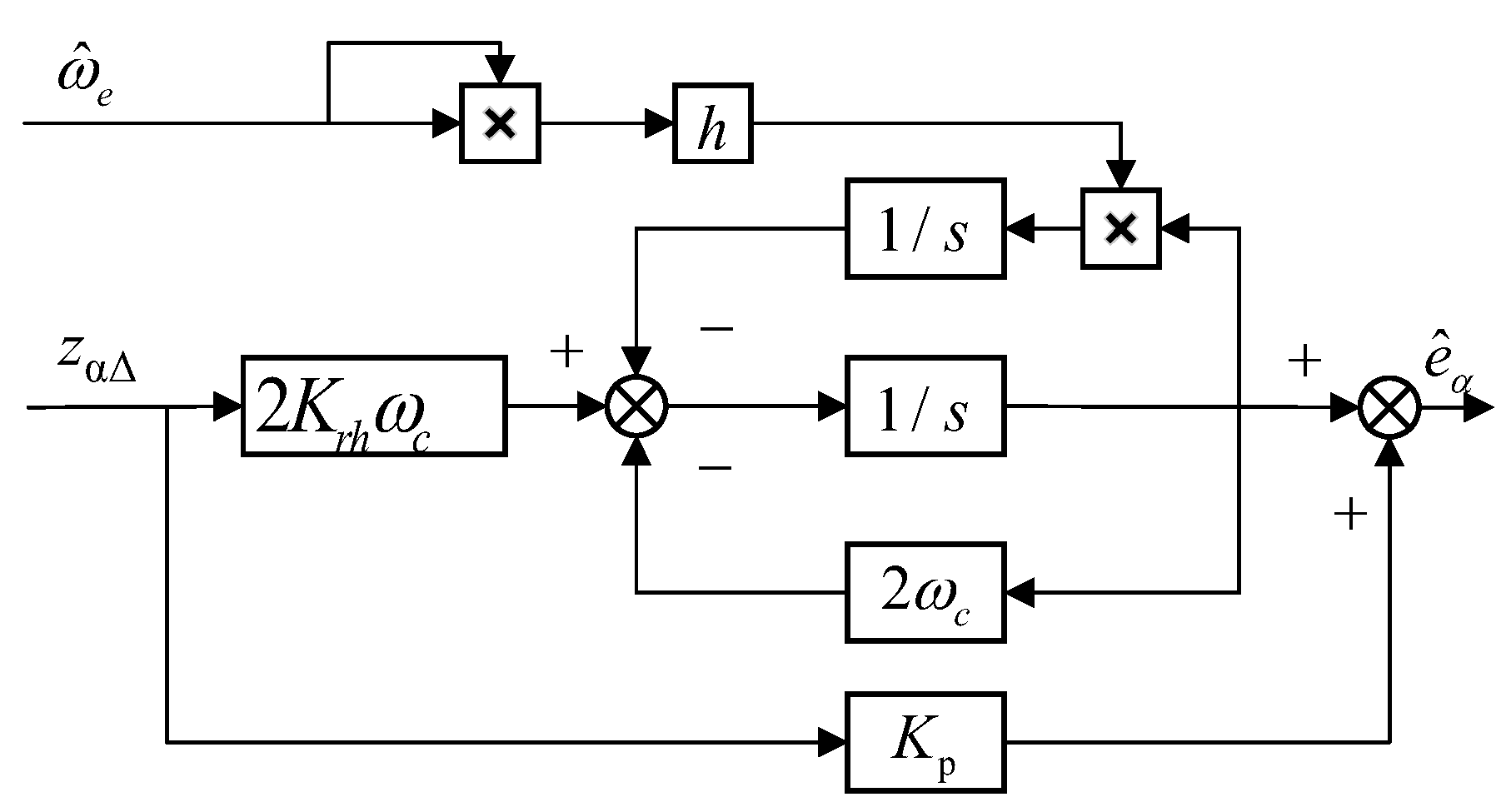
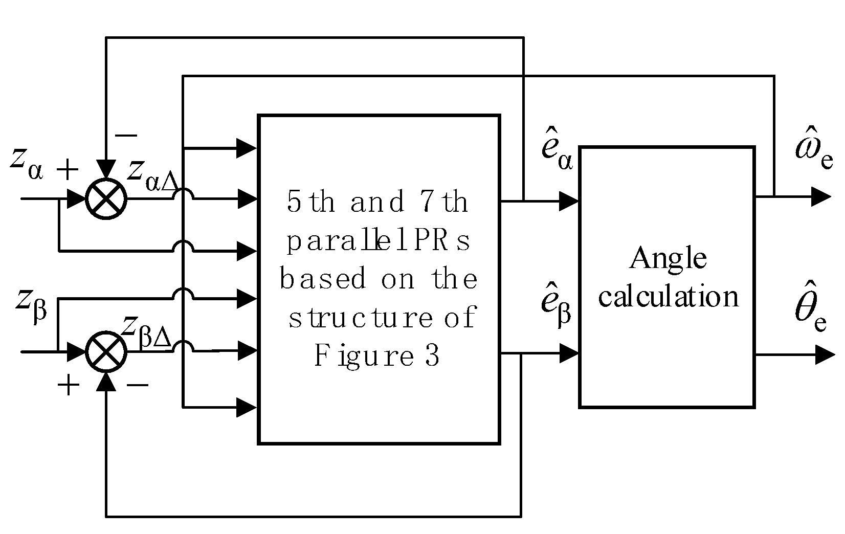
4.1. Improvement Measures Based on Multi-Proportional Resonant Filter

Due to the influence of uncertain factors such as mechanical tolerances, temperature changes, and space harmonics, it is impossible to eliminate the harmonic components in the estimated back EMF. The harmonic components are mainly caused by two reasons, one is the nonlinearity of the inverter, and the other reason is that permanent magnets cannot be exactly the same. Traditional SMO usually uses LPF to filter out the harmonics, but the LPF will lead to system phase delay, so rotor angle compensation is required [24,25]. In this paper, an improved SMO algorithm was proposed that uses a multi-proportional resonant filter to replace the LPF, which simplifies the system structure and solves the problems of phase lag and angle compensation.
Wang Gaolin pointed out in [20] that the nonlinearity of the inverter leads to the existence of the 5th harmonic and the 7th harmonic in the estimated back EMF, which has always existed in power electronic applications.
The proportional resonance controller (PR) can realize the tracking of the AC signal without static error, and the gain at the resonance point is infinite, which can achieve the effect of suppressing harmonics. The transfer function of an ideal PR controller is shown in Equation (18):
G P R ( s ) = K p + K r s s 2 + ω 0 2
where Kp is the proportional gain, Kr is the resonance gain, and ω0 is the resonance angular frequency. Since the back EMF is mainly the fundamental frequency component, ω 0 = ω ^ e here.
Since the bandwidth of the ideal PR controller is narrow and the frequency response gain is infinite, the system is sensitive to parameter changes, and the ideal PR controller is difficult to achieve in the actual control. In this paper, a quasi-proportional resonant controller (QPR) was used to estimate the back EMF. QPR can effectively widen the filtering bandwidth, and its transfer function is:
G P R ( s ) = K p + 2 K r ω c s s 2 + 2 ω c s + ω 0 2
Since there are mainly (6k ± 1) f harmonics in the back-EMF, the specific frequency harmonics in the estimated back EMF can be filtered out by paralleling multiple quasi proportional resonance controllers. The transfer function of the multi-proportional resonant filter (MPF) can be expressed as:
G MPR ( s ) = K p + h = 5 , 7 2 K r h ω c s s 2 + 2 ω c s + ( h ω 0 2 )
where h is the harmonic order, and Krh is the resonance gain of the h-order harmonic.
Based on the open-loop transfer function of the QPR filter shown, its structural block diagram is shown in Figure 3. Taking the αaxis as an example, h is the harmonic order, the estimated electrical angular velocity ω ^ e is the resonant frequency of the MPF, and the output is the filtered back EMF.
The parallel connection composed of multiple PR controllers is shown in Figure 4.
Firstly, multiple PR controllers were designed in parallel to extract the negative sequence components of the 5th and 7th harmonics in the back EMF, and then the extracted components were compensated into the back EMF, which achieved the effect of suppressing harmonics. The closed-loop structure is shown in Figure 5.
The zα, zβ containing the harmonics of the back EMF were filtered by the closed-loop MPF, and the filtered back EMF e ^ α   e ^ β was obtained. At the same time, the back EMF zα, zβ containing harmonics and the back EMF error zα∆, zβ∆ were used as the input signal of the PR controller, to form the closed-loop control. The rotor position θ ^ e and electrical angular velocity ω ^ e were calculated by the angle calculation module.

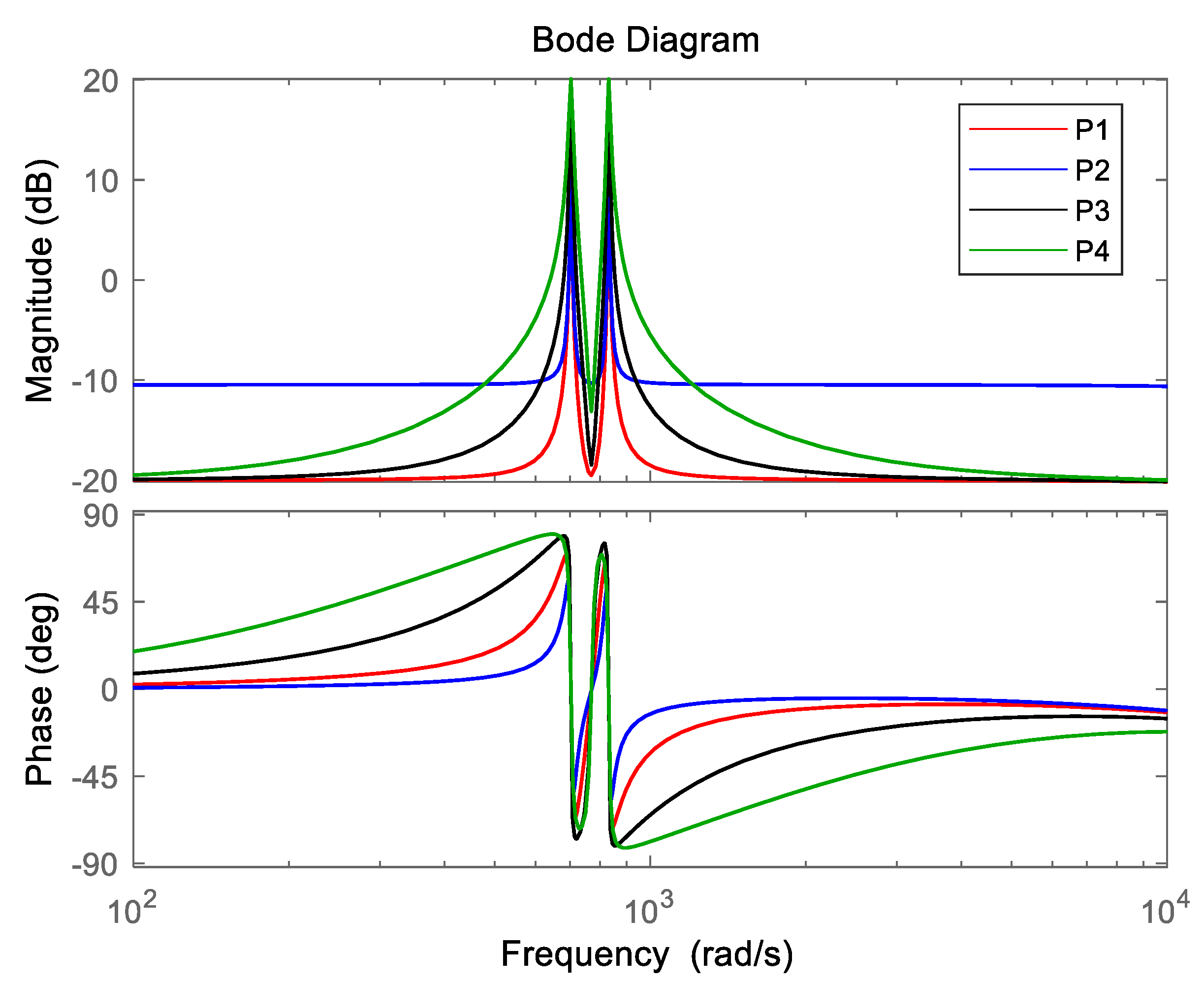
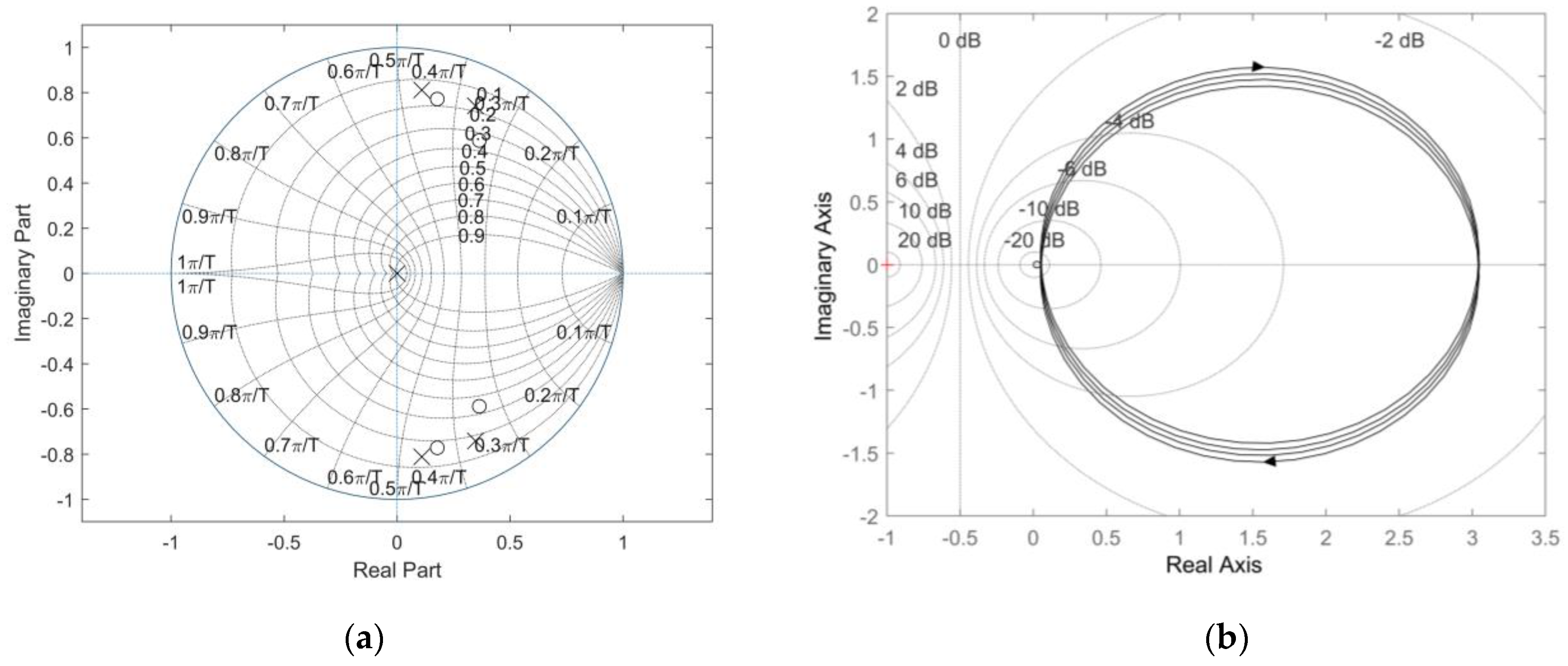
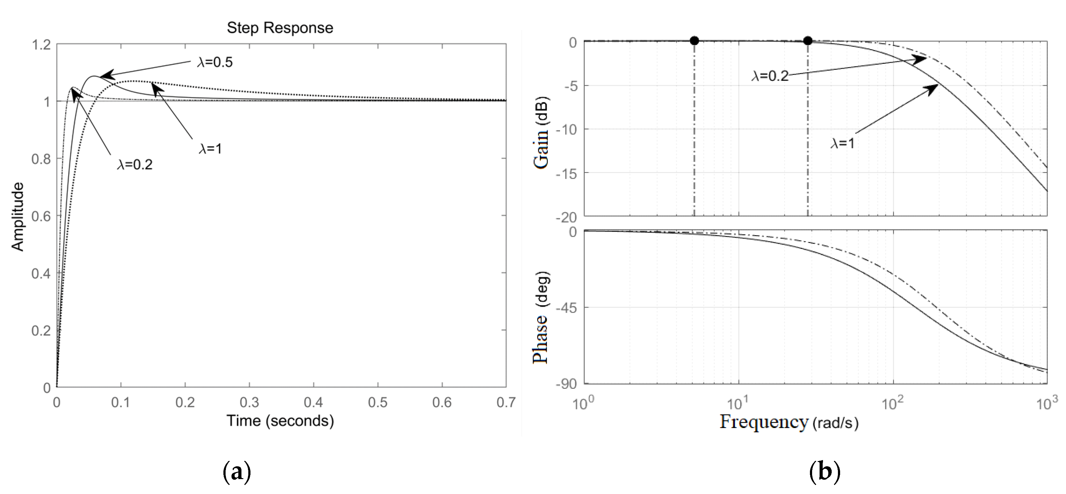
4.2. Parameter Design and System Stability Analysis

Since the surface-mounted permanent magnet synchronous motor can be approximated as a non-salient pole motor, the effective flux linkage model is introduced to simplify the mathematical model of the motor, which is defined as:
{ T e = 3 2 P n [ ψ f + ( L d L q ) i d ] i q ψ a = ψ f + ( L d L q ) i d
where ψ a is the permanent magnet flux linkage, and Ld and Lq are the direct axis and quadrature axis inductance, respectively.
When the system reaches the sliding mode surface, the system will move along the sliding mode surface. At this time, the control function only moves in the boundary layer, then z α , β can be expressed as:
z α , β = k ( i ^ s i s )
From Equations (2), (7) and (22), the function of the MPF with the closed-loop control can be expressed as:
G ( s ) = e ^ α ( β ) ( s ) e α ( β ) ( s ) = k L s + R + k G MPF ( s ) 1 + G MPF ( s )
The motor parameters in Table 1 are substituted into the transfer function of Equation (23), L = 0.15 mH, R = 0.1 Ω. The value of the switching gain of k is 200, and Figure 6 shows the system bode diagram under different parameters, such as P1 (Kp = 0.1, Kr5 = 3, Kr7 = 5, ωc = 2), P2 (Kp = 0.3, Kr5 = 3, Kr7 = 5, ωc = 2), P3 (Kp = 0.1, Kr5 = 5, Kr7 = 5, ωc = 2), and P4 (Kp = 0.1, Kr5 = 3, Kr7 = 5, ωc = 5). The resonant frequency ω 0 is defined as 314 rad/s.
It can be seen from Figure 6 that the control system had a high gain near the 5th and 7th harmonics and had a good follow-up performance for these harmonics. Different parameter values of K p , K r 5 , K r 7 , and ω c affected the filtering effect and the bandwidth of the system. Considering the filter performance and dynamic response performance of the system, this paper comprehensively selected K p   = 0.2, K r 5   = 3, K r 7   = 5, ω c   = 2.
By using a bilinear transformation, the discrete open-loop model between the estimated back-EMF and the actual back-EMF based on the MPF observer is:
G ( z ) = z 1 Z ( G ( s ) )
where z is a discrete operator.
Figure 7 is the pole-zero diagram and the Nyquist diagram, respectively.
From Figure 7a, the poles of the system are all within the unit circle, so the impulse response curve of the system converged with the increase of frequency, and it can be seen from the Nyquist curve of the system in Figure 7b that the system did not surround the (−1,0) point; thus, the improved SMO system designed is stable.

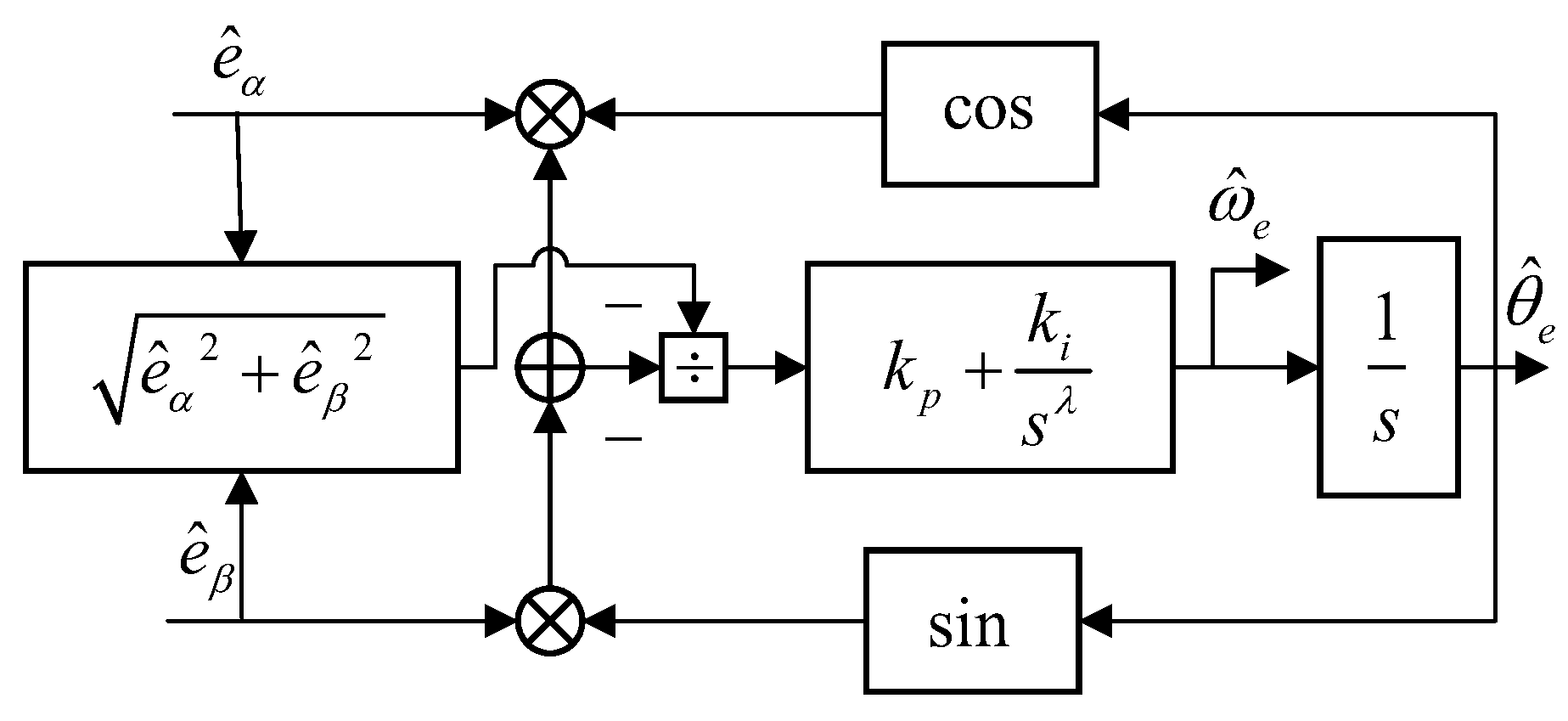
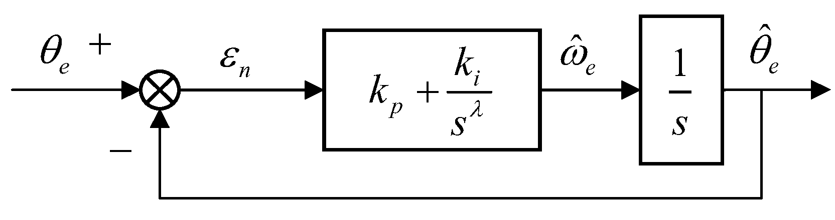
5. Rotor Position and Speed Estimation Based on FN-PLL

Tradition SMO rotor angular velocity and velocity were calculated using arctangent, as shown in Equations (15) and (16), which often have poor accuracy. An improved FN-PLL was designed to improve the calculation accuracy and eliminate the high-frequency noise. Figure 8 and Figure 9 are the block diagrams of the FN-PLL structure. Firstly, the back EMF was normalized, and then fractional integration was used instead of integer integration.
ε n = e ^ α cos ( θ ^ e ) e ^ β sin ( θ ^ e ) e ^ α 2 + e ^ β 2 = sin ( θ e θ e )
When the estimation error of the rotor position is in the range of | θ e θ ^ e | π / 6 , then the back EMF error εn can be approximated as:
ε n = sin ( θ e θ ^ e ) θ e θ ^ e = Δ θ
According to (26), it can be seen when the rotor estimation error is small enough that the FN-PLL can accurately estimate the rotor position. Therefore, the FN-PLL closed-loop transfer function G FN - PLL and the error transfer function G e can be expressed as:
G FN - PLL = θ ^ e θ e = k p s λ + k i s 1 + λ + k p s λ + k i
G e = ε n θ ^ e = s λ + 1 s λ + 1 + k p s λ + k i
where kp is the proportional gain, ki is the integral gain, and λ (0 < λ < 1) is the hierarchical factor. It can be seen from (27) that the back EMF was not included in the FN-PLL transfer function; thus its performance will not be affected by the change of speed, and the FN-PLL can effectively improve the robustness of the system. On the other hand, fractional integration has more degrees of freedom than integer integration. Therefore, FN-PLL achieves better performance by appropriate sequential selection.
When the motor operates in steady state, it can be approximated as:
d ω ^ e / d t 0
At this time, θ ^ e is approximately a slope function, and it can be expressed as:
θ ^ e = k v t
Then, the steady-state output error of FN-PLL is deduced as:
Δ e ( ) = lim x 0 s Δ e ( s ) = lim x 0 s λ s λ + 1 + k p s r + k i 0
In order to further analyze the influence of the fractional order on system performance, the influence of the change of integral order λ on system performance was studied, and different λ values were selected to analyze the phase-locked loop frequency characteristic curve. Figure 10a is the step response of the phase-locked loop for different values of λ.
It can be clearly seen from Figure 10a that when λ = 1, the overshoot, adjustment time, and peak time of the system are 0.09%, 0.456 s, and 0.145 s, respectively. When λ = 0.5, the overshoot, adjustment time of the system, and the peak time are 0.1%, 0.196 s, and 0.08 s, respectively; when λ = 0.2, the overshoot, adjustment time, and peak time of the system are 0.06%, 0.11 s, and 0.051 s, respectively. It can be seen from the data and the figure that, with the decrease of the λ value, the overshoot, adjustment time, and system peak time of the system improved to a certain extent. At the same time, it can be seen from the bode diagram in Figure 10b that the FN-PLL system with different λ values had a different bandwidth and phase delay. Its bandwidth varied with increases with decreasing fractional order, and the phase lag decreased with decreasing fractional order. However, the λ value should not be too small, which will increase the calculation time of the controller. Therefore, it is necessary to comprehensively consider and select an appropriate value according to different motor system characteristics to obtain a higher estimation accuracy.

6. Simulation Analysis

To evaluate the performance of the improved SMO, a simulation model of the proposed observer was established. The PMSM sensorless control system designed in this paper adopted the id = 0 control strategy. Table 1 shows the parameter settings of the PMSM.
Figure 11 is the control block diagram of the improved sliding mode observer PMSM without a position sensor.

6.1. Simulation Analysis of Low-Speed Operation

In order to verify the filtering effect of the improved rotor position observer, the back EMF results of the traditional SMO and the improved SMO in this paper were compared and analyzed. Figure 12a shows the back-EMF waveform of the traditional SMO running at 450 rpm under half-load conditions. It can be seen from the figure that, although the back EMF waveform presented a sinusoidal shape, it was accompanied by small-amplitude chattering in the waveform. Figure 12c is the FFT analysis of the traditional SMO back EMF. The back EMF mainly existed in the fifth and the seventh harmonics. Figure 12b shows the modified SMO back EMF. The back EMF was smoother than that in Figure 12a, and the chattering was significantly reduced. Through the FFT analysis of the improved SMO back EMF in Figure 12d, the fifth and seventh harmonics in the back EMF were significantly reduced, and the total harmonic was only 2.9%.
Figure 13 and Figure 14 show the simulation results of the rotor speed and position estimation results of the traditional SMO and the improved SMO.
It can be seen from Figure 13a that the speed error of the traditional SMO was about 5 rpm, which is relatively large, and it can be seen from Figure 13b that the rotor position had a great chattering problem. From Figure 14a,b, it can be seen that the speed error and the position error were greatly improved, the estimated speed and actual speed of the improved SMO under the steady state operation were almost equal, and the waveform was smooth. However, it can be seen from the traditional SMO back EMF waveform in Figure 12a that there was a certain amount of chattering and harmonics in the waveform; thus, the estimation accuracy of the rotor and speed was also reflected in the back EMF.

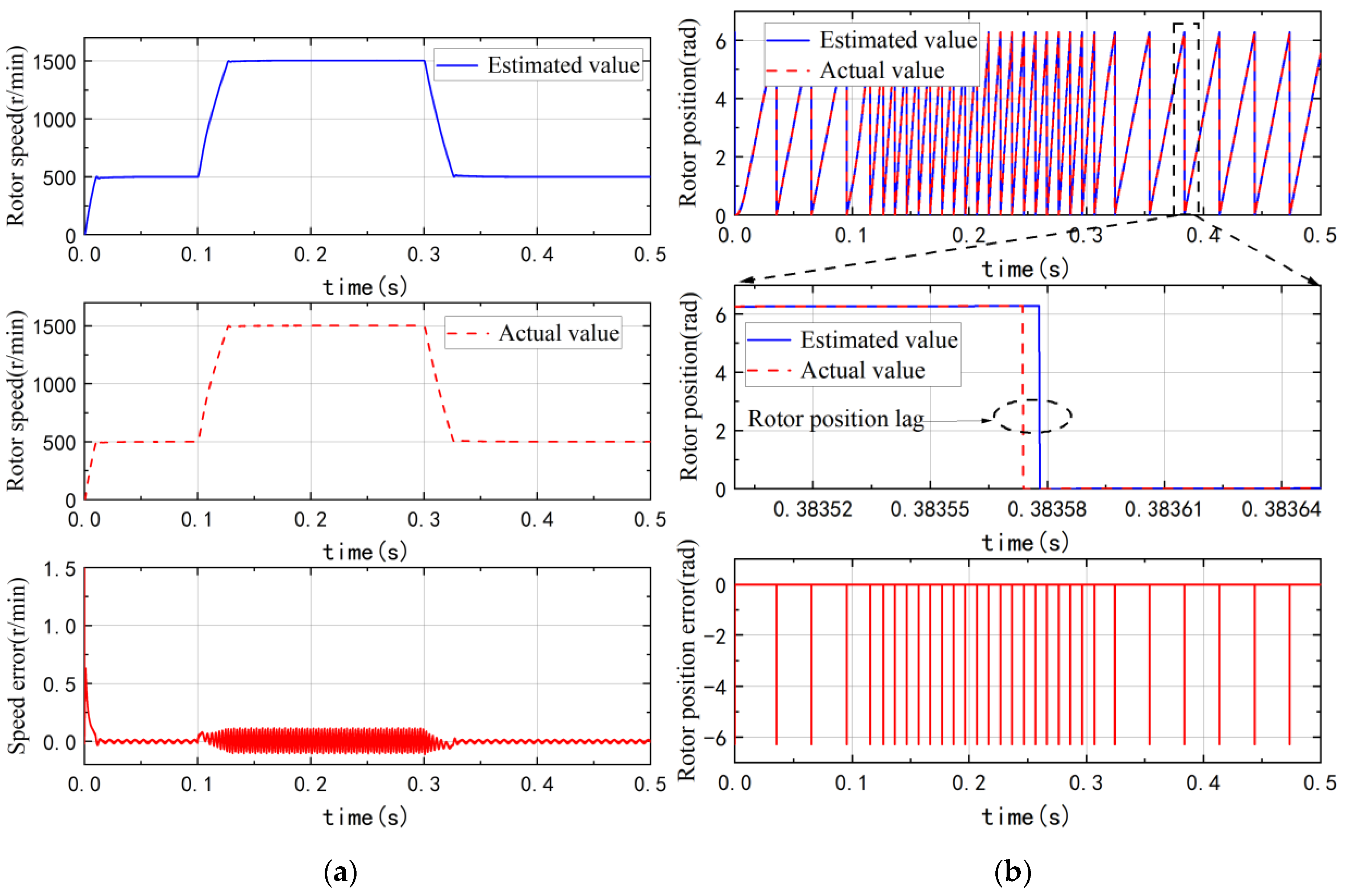
6.2. Simulation Analysis of Variable-Speed Operation

In order to verify the dynamic performance of the improved SMO, under the condition of constant load, the speed reference signal changed from 500 rpm to 1500 rpm at 0.1 s and from 1500 rpm to 500 rpm at 0.3 s, and the waveforms of rotor speed and rotor position were analyzed. Figure 15 and Figure 16 show the observation results of rotor speed and position when using the traditional SMO and the improved SMO, respectively.
As can be seen from Figure 15a, the maximum speed error was about 0.5 rpm when the speed was 500 rpm, but when the reference speed suddenly changed, the speed and position errors increased significantly. The difference between the actual speed and the estimated speed was about 2 rpm.
As shown in Figure 16, using the improved SMO control strategy, the estimated speed and actual speed of the motor were basically coincident when the speed was 500 rpm, and when the reference speed changed, the estimated error was about 0.1 rpm at most. At the same time, from the simulation results of the traditional SMO rotor position in Figure 15b and the improved rotor position in Figure 16b, due to the LPF existing in the traditional SMO and the phase compensator, it can be clearly seen that the rotor position lag was relatively large, while the improved SMO obtained higher control accuracy for the rotor position estimation due to the use of MPF.

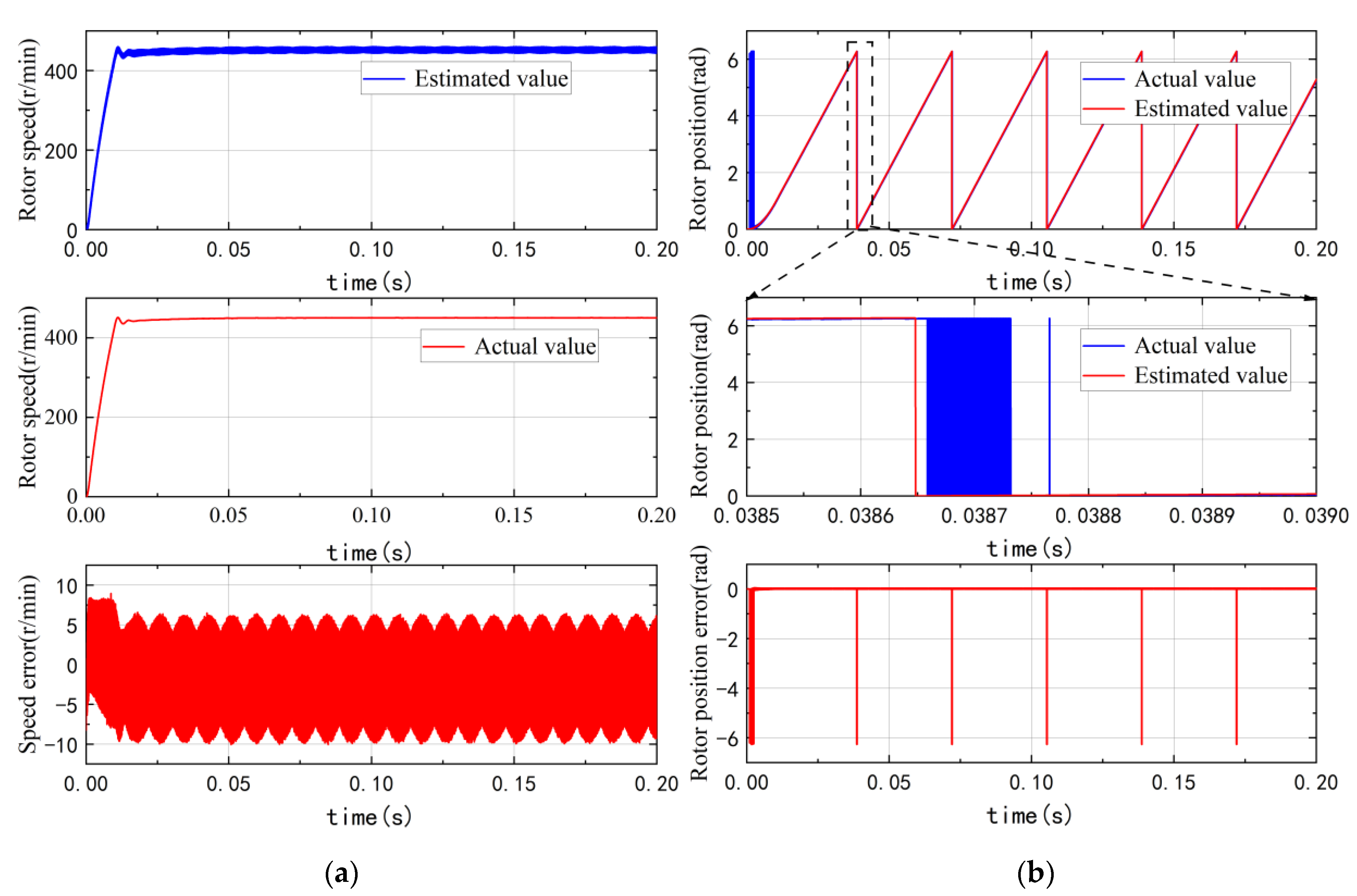
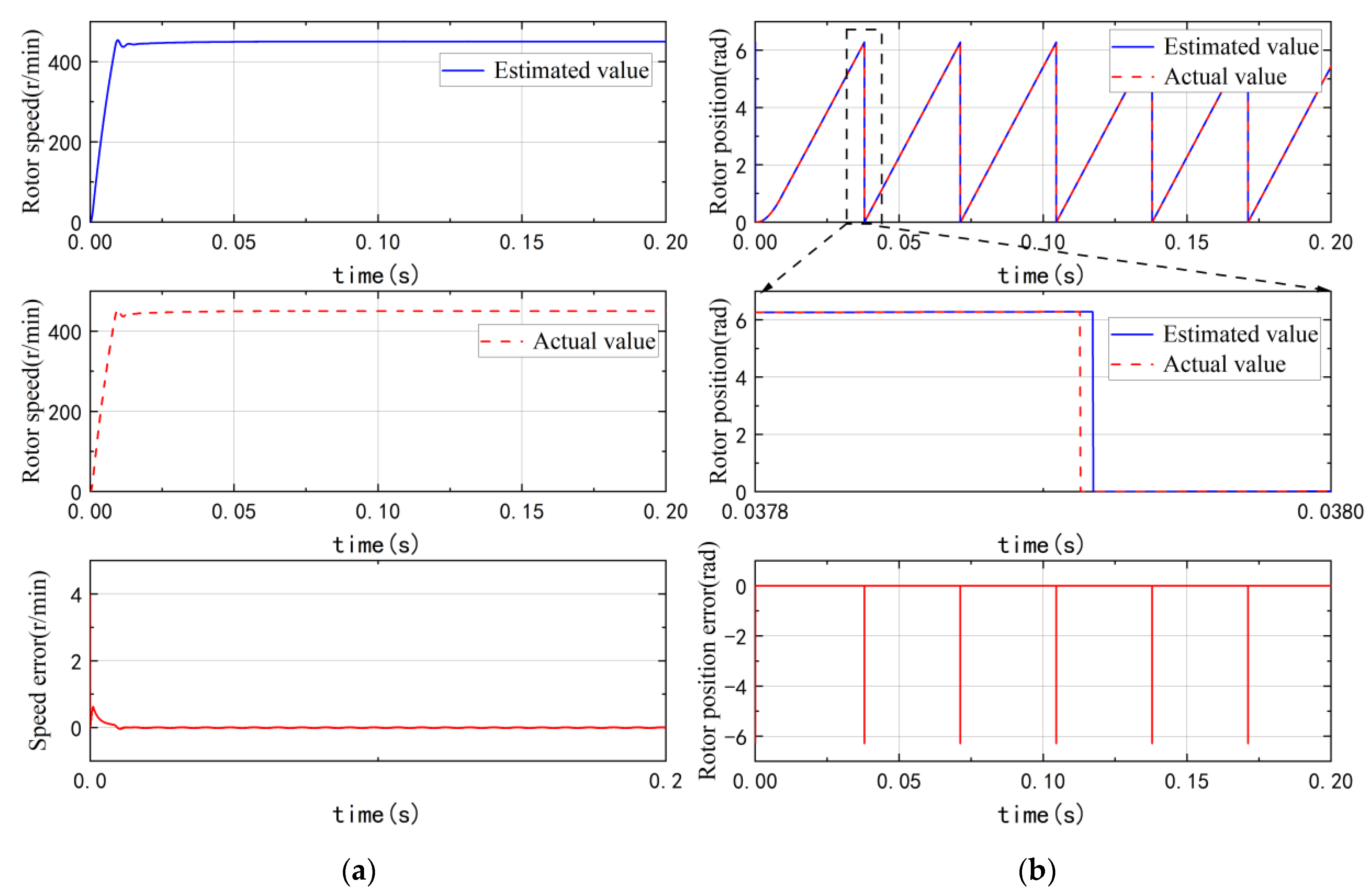
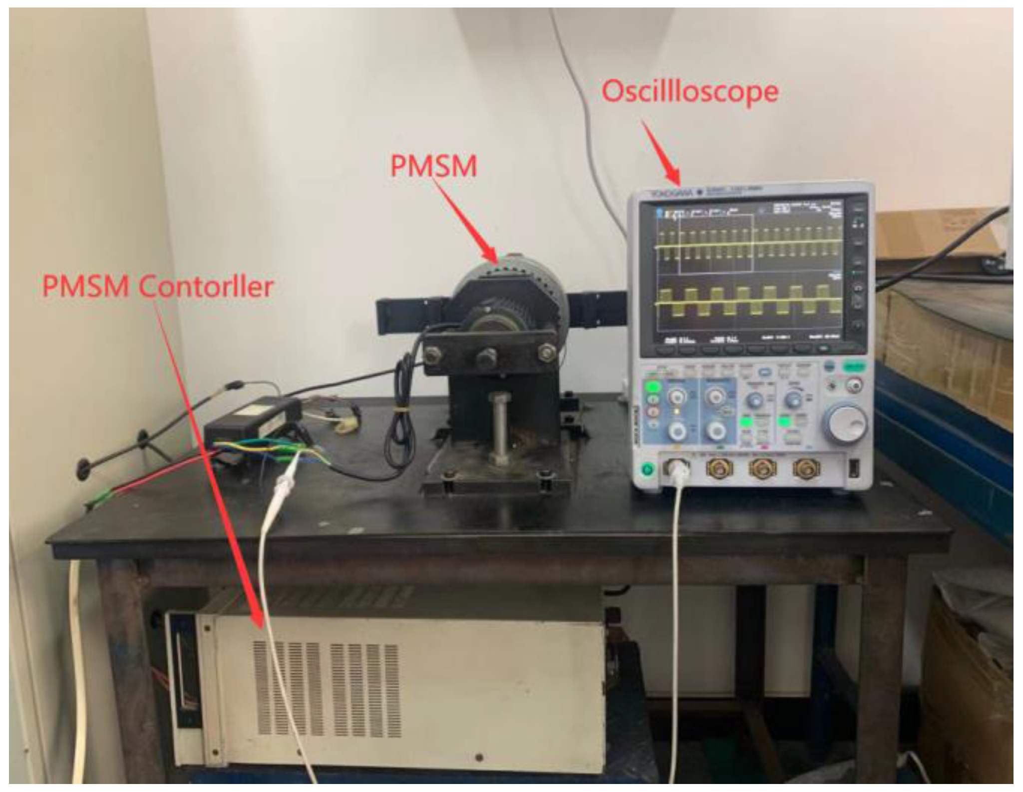
7. Experimental Verification

In order to verify the feasibility of the improved SMO proposed in this paper, the experimental platform was built up. As shown in Figure 17, the experiment system includes the following parts: (1) a permanent magnet synchronous motor with 4p/36 slots; (2) a motor control board developed based on TMS28335; (3) a DC power supply; (4) an oscilloscope of YOKOGAWA. In this experiment, the switching frequency of the inverter was 12.5 kHz, the dead time was 3μs, and the cutoff frequency of the experimental low-pass filter was 2000 Hz.

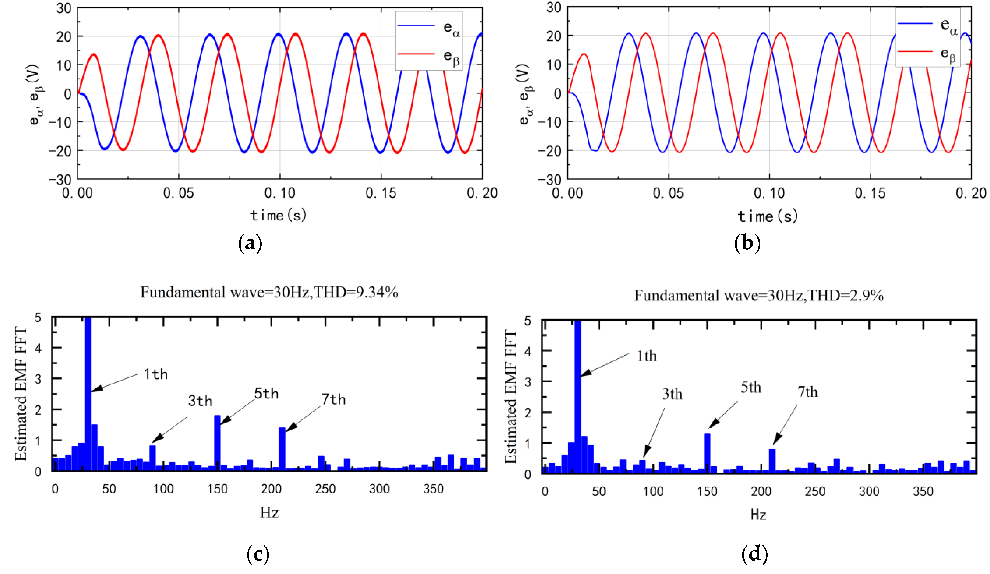
7.1. Harmonic Analysis

Figure 18 shows the back EMF waveform of the motor operation at the rated load. Figure 18a,b is the back EMF of the traditional SMO and the improved SMO, respectively. It can be clearly seen from Figure 18a that the back-EMF of the traditional SMO had large harmonics and obvious chattering. The harmonics and chattering in the back-EMF will increase the rotor position and speed error. Compared with the traditional SMO back-EMF waveform, it can be seen from Figure 18b that the harmonics and chattering of the back-EMF waveform were significantly improved, the waveform was smoother, and the eα and eβ were close to perfect sinusoidal waveforms. The experiments showed that the modified SMO was significantly improved in terms of back EMF harmonics.
It can be seen from the FFT analysis of the waveforms in Figure 18c that the 5th and 7th orders of the back EMF harmonics occupied a large proportion, which is also one of the reasons for the large speed and rotor position errors. The content of the 5th and 7th harmonics in the back EMF after proportional resonance filtering in Figure 18d was significantly reduced.
Figure 19 shows the rotor position estimation results of the traditional SMO and the improved SMO at 1500 rpm and 50% load. The measured value was the actual rotor position measured by the photoelectric encoder. From the traditional SMO experimental results in Figure 19a, due to the use of the sign function and the low-pass filter, the estimated back EMF had many high-order harmonics, which led to the rotor position estimation error being large, and there was an obvious chattering problem in the waveform, which can also be seen from Figure 19a. Compared with the improved SMO in Figure 19b, the rotor position error was about 0.1 rad, and its estimation accuracy was significantly improved compared to traditional SMO.
Figure 20a,b is the rotor speed of the traditional SMO and the improved SMO at 1500 rpm, respectively. It can be clearly seen that the maximum speed estimation error of the traditional SMO was about 2 rpm. However, based on the MPF improvement, the maximum velocity estimation error of the modified SMO was reduced to about 0.8 rpm, and the experimental results showed that the improved SMO had better observation accuracy.

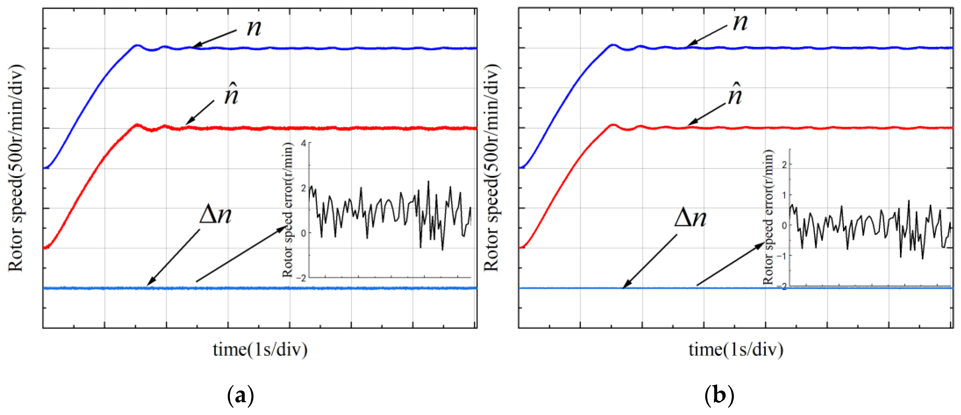
7.2. Anti-Disturbance Dynamic Analysis

In order to analyze the anti-disturbance response effect of the improved SMO control, the torque was first abruptly changed from 0 N to 10 N and then suddenly changed to 0 N. Figure 21a shows the experimental results of loading and unloading of traditional SMO control. It can be seen that, after loading, the speed dropped by 30 rpm, the time to return to a steady state after the load changes was about 8 ms, and the sudden change of load also increased the speed error instantly. It can be seen from the waveform of the improved SMO speed in Figure 21b that when the load changed abruptly, the speed dropped by about 5 rpm, and the time to return to a steady state after the load changes was about 6 ms. It can be seen from the comparison that the improved SMO proposed in this paper has a great improvement compared with the traditional SMO in the case of sudden load changes; not only are the speed and rotor position errors smaller in the steady state, but they also are under the load. In the case of sudden change, it can maintain good dynamic performance and ensure the control accuracy of the system.

8. Conclusions

In this paper, an improved rotor position observer with sliding mode control strategy of permanent magnet synchronous motor was studied.
  • A MPF was designed instead of LPF to reduce the chattering in the traditional SMO back EMF and eliminate the system phase delay. The parameter design of MPF was analyzed. Using the frequency response analysis, the relationship between the main parameters and the stability margin was discussed and summarized. Then, the improved FN-PLL was used to calculate the rotor position and speed, which simplified the system structure. The stability of the improved SMO was verified by the pole-zero and Nyquist theory of the discrete model.
  • The simulation model was built to verify the proposed control strategy. Through the analysis of the simulation results, compared with the traditional SMO, the total harmonic distortion (THD) in the back EMF in the improved SMO was reduced by 6.14%, the chattering was suppressed while the system phase delay was eliminated, and the estimated accuracy of position and speed were improved; the performance of the improved SMO was verified by simulation.
  • The experimental platform was built up and showed that the improved SMO has the following advantages. The experimental results show that MPF can effectively eliminate the selective frequency harmonic content of the estimated back EMF; under different working conditions, such as load and speed transients, the position error and speed error of the improved SMO were also significantly improved compared with the traditional SMO, which helps to improve the sensorless control performance of the PMSM driver.

Author Contributions

Conceptualization, H.L. and Q.S.; methodology, H.L. and L.Z.; software, L.Z. and J.D.; hardware, H.L. and L.Z.; validation, H.L., L.Z., and X.C.; data curation, C.Y.; writing—original draft preparation, L.Z.; writing—review and editing, H.L. and J.D.; visualization, J.D.; supervision, H.L. and Q.S.; project administration, H.L.; funding acquisition, H.L. All authors have read and agreed to the published version of the manuscript.

Funding

This research was funded by the Special Foundation for Technology Innovation Guidance of Tianjin, grant number 20YDTPJC01350; and in the part by the Scientific Research Project of Tianjin Municipal Education Commission under grant 2020KJ093.

Institutional Review Board Statement

Not applicable.

Informed Consent Statement

Not applicable.

Data Availability Statement

Not applicable. The study did not report any data, the authors chose to exclude this statement.

Conflicts of Interest

The authors declare no conflict of interest.

References

  1. Hu, S.; Hu, B.; Wang, W.; Cao, W. Analysis of loss-of-excitation characteristics of permanent magnets of high-density permanent magnet synchronous motors. Chin. J. Electr. Eng. 2019, 14, 121–126. [Google Scholar]
  2. Wang, L.; Kong, X.; Yu, G. Parameter tuning of motor servo control of parallel-hybrid machine tool based on genetic algorithm. J. Tsinghua Univ. (Nat. Sci. Ed.) 2021, 61, 1106–1114. [Google Scholar] [CrossRef]
  3. Zhang, Y.; Liu, J. An improved Q-PLL to overcome the speed reversal problems in sensorless PMSM drive. In Proceedings of the 2016 IEEE 8th International Power Electronics and Motion Control Conference (IPEMC-ECCE Asia), Hefei, China, 22–26 May 2016; IEEE: Piscataway, NJ, USA, 2016; pp. 1884–1888. [Google Scholar]
  4. Lu, W. Research on Sensorless Vector Control Technology of Permanent Magnet Synchronous Motor. Ph.D. Thesis, Southeast University, Dhaka, Bangladesh, 2016. [Google Scholar]
  5. Li, H.; Chen, T. Review of parameter identification of permanent magnet synchronous motor. J. Electron. Meas. Instrum. 2015, 29, 638–647. [Google Scholar]
  6. Liu, J.; Xiao, F.; Shen, Y.; Mai, Z.; Li, C. Research review on position-free sensor control technology of permanent magnet synchronous motor. Electrotech. J. 2017, 32, 76–88. [Google Scholar]
  7. Zhang, Y.; Wang, W.; Zhang, X.; Xiao, X.; Shang, J. Improved sliding mode observation method of permanent magnet synchronous motor with resistance online identification. J. Electr. Mot. Control. 2017, 21, 10–17, 25. [Google Scholar]
  8. Li, R.; Zhao, G.; Xu, S. Sensorless control of permanent magnet synchronous motor based on extended sliding mode observer. Trans. China Electrotech. Soc. 2012, 3, 79–85. [Google Scholar]
  9. Chen, S.; Pi, Y. Position sensorless control of permanent magnet synchronous motor based on sliding mode observer and sliding mode controller. J. Electrotech. Technol. 2016, 31, 108–117. [Google Scholar]
  10. Chen, Y.; Gao, Y.; Chen, Z. A sliding-mode observer combining an adaptive synchronous filter and an orthogonal phase-locked loop. Electrotech. J. 2018, 33, 265–274. [Google Scholar]
  11. Liu, Z.; Chen, W. Research on an Improved Sliding Mode Observer for Speed Estimation in Permanent Magnet Synchronous Motor. Processes 2022, 10, 1182. [Google Scholar] [CrossRef]
  12. Huang, Y.; Wu, F. A Sensorless Control Method for Permanent Magnet Synchronous Motor Based on Fractional-Order Sliding Mode Observer. In 2020 Industry Applications, Proceedings of the IEEE 5th Information Technology and Mechatronics, Chongqing, China, 12–14 June 2020; IEEE: Piscataway, NJ, USA, 2020; Volume 53, pp. 3672–3682. [Google Scholar]
  13. Wang, Q.; Zhang, X.; Zhang, C. Permanent magnet synchronous motor vector control dual-sliding mode model refers to the adaptive system speed identification. Chin. J. Electr. Eng. 2014, 34, 897–902. [Google Scholar]
  14. Nguyen, A.T.; Rafaq, M.S.; Choi, H.H.; Jung, J.W. A model reference adaptive control based speed controller for a surface-mounted permanent magnet synchronous motor drive. IEEE Trans. Ind. Electron. 2018, 65, 9399–9409. [Google Scholar] [CrossRef]
  15. Gopinath, G.R.; Das, S.P. An extended Kalman filter based sensorless permanent magnet synchronous motor drive with improved dynamic performance. In Proceedings of the 2018 IEEE International Conference on Power Electronics, Drives and Energy Systems (PEDES), Xiamen, China, 18–21 December 2018; IEEE: Piscataway, NJ, USA, 2018; pp. 1–6. [Google Scholar]
  16. Bolognani, S.; Calligaro, S.; Petrella, R. Design issues and estimation errors analysis of back-EMF-based position and speed observer for SPM synchronous motors. IEEE J. Emerg. Sel. Top. Power Electron. 2014, 2, 159–170. [Google Scholar] [CrossRef]
  17. Li, H.; Zhang, X.; Yang, S.; Li, E. Review of sensor-less control technology of permanent magnet synchronous motor based on high-frequency signal injection. Electrotech. J. 2018, 33, 2653–2664. [Google Scholar]
  18. Kim, S.Y.; Lee, W.; Rho, M.S.; Park, S.Y. Effective dead-time compensation using a simple vectorial disturbance estimator in PMSM drives. IEEE Trans. Ind. Electron. 2009, 57, 1609–1614. [Google Scholar]
  19. Choi, Y.S.; Shin, H.C.; Song, W.J. Robust regularization for normalized LMS algorithms. IEEE Trans. Circuits Syst. II Express Briefs 2006, 53, 627–631. [Google Scholar] [CrossRef]
  20. Wang, G.; Zhan, H.; Zhang, G.; Gui, X. Adaptive compensation method of position estimation harmonic error for EMF-based observer in sensorless IPMSM drives. IEEE Trans. Power Electron. 2013, 29, 3055–3064. [Google Scholar] [CrossRef]
  21. Wang, G.; Ding, L.; Li, Z.; Xu, J.; Zhang, G.; Zhan, H.; Ni, R.; Xu, D. Enhanced position observer using second-order generalized integrator for sensorless interior permanent magnet synchronous motor drives. IEEE Trans. Energy Convers. 2014, 29, 486–495. [Google Scholar]
  22. Du, S.; Quan, L.; Zhu, X.; Zhang, L.; Zuo, Y. Fault-tolerant control of position sensor failure at zero and low speed of permanent magnet synchronous motor based on high frequency injection. Chin. J. Electr. Eng. 2019, 39, 3038–3047. [Google Scholar]
  23. Jiang, Y.; Li, B.; Wu, X.; Huang, S.; Huang, K.; Xiao, S.; Zhang, X. Improved permanent magnet synchronous motor rotor position observer based on proportional resonant filter. Electrotech. J. 2020, 35, 3619–3630. [Google Scholar]
  24. Pugi, L.; Grasso, E.; Fabbri, S. Enhanced Back EMF Sensorless Control for Permanent Magnet Synchronous Motors. In Proceedings of the 2018 IEEE International Conference on Environment and Electrical Engineering and 2018 IEEE Industrial and Commercial Power Systems Europe (EEEIC/I&CPS Europe), Palermo, Italy, 12–15 June 2018; IEEE: Piscataway, NJ, USA, 2018; pp. 1–6. [Google Scholar]
  25. Ali, S.; Raza, M.T.; Abbas, G.; Ullah, N.; Al Otaibi, S.; Luo, H. Sliding Mode Observer-Based Fault Detection in Continuous Time Linear Switched Systems. Energies 2022, 15, 1090. [Google Scholar] [CrossRef]
Figure 1. PMSM vector diagram under d-q coordinate and α-β coordinate.
Machines 10 00633 g001
Figure 2. Traditional sliding mode observer.
Machines 10 00633 g002
Figure 3. Block diagram of the QPR filter.
Machines 10 00633 g003
Figure 4. Parallel module composed of multiple PR controllers.
Machines 10 00633 g004
Figure 5. Closed-loop control block diagram of MPF.
Machines 10 00633 g005
Figure 6. System bode diagram under different parameters.
Machines 10 00633 g006
Figure 7. Pole-zero and Nyquist diagram: (a) Pole-zero diagram; (b) Nyquist diagram.
Machines 10 00633 g007
Figure 8. FN-PLL block diagram.
Machines 10 00633 g008
Figure 9. FN-PLL equivalent Diagram.
Machines 10 00633 g009
Figure 10. Step Responses for Different λ Values and Bode Plots: (a) step response with different λ; (b) bode diagram with different λ.
Machines 10 00633 g010
Figure 11. Block diagram of improved rotor position observer.
Machines 10 00633 g011
Figure 12. Back EMF waveform at low speed; (a) back EMF with traditional SMO control; (b) back EMF with improved SMO control; (c) traditional SMO simulation back EMF FFT analysis; (d) improved SMO simulation back-EMF FFT analysis.
Machines 10 00633 g012
Figure 13. Speed and position estimation results of traditional SMO at low speed: (a) rotor speed; (b) rotor position.
Machines 10 00633 g013
Figure 14. Speed and position estimation results of improved SMO at low speed: (a) rotor speed; (b) rotor position.
Machines 10 00633 g014
Figure 15. Speed and position estimation results of traditional SMO with LPF at variable-speed operation: (a) rotor speed; (b) rotor position.
Machines 10 00633 g015
Figure 16. Speed and position estimation results of improved SMO with MPF at variable-speed operation: (a) rotor speed; (b) rotor position.
Machines 10 00633 g016
Figure 17. Experimental system platform.
Machines 10 00633 g017
Figure 18. Back EMF experimental results: (a) traditional sliding mode back-EMF waveforms; (b) improved sliding mode back-EMF waveform; (c) FFT analysis of traditional sliding mode back EMF; (d) FFT analysis of improved sliding mode back-EMF waveform.
Machines 10 00633 g018
Figure 19. Rotor position experimental results: (a) traditional SMO rotor actual position, estimated position and position error; (b) improved SMO rotor actual position, estimated position, and position error.
Machines 10 00633 g019
Figure 20. Rotor speed experimental results: (a) traditional SMO; (b) improved SMO.
Machines 10 00633 g020
Figure 21. Rotor speed loading experimental results: (a) traditional SMO; (b) improved SMO.
Machines 10 00633 g021
Table 1. Motor parameters.
ParameterParameter Value
Polar pairs p4
Rated speed n (rpm)2000
Torque Te (N·m)14.3
Stator resistance R (Ω)0.1
Stator inductance L (H)0.0015
Rated voltage Udc (V)300
Speed PI parameters1, 0.2
Current PI parameter3, 20
Publisher’s Note: MDPI stays neutral with regard to jurisdictional claims in published maps and institutional affiliations.

