Article

Integrated Impacts of Non-Ideal Factors on the Vibration Characteristics of Permanent Magnet Synchronous Motors for Electric Vehicles

1
Key Laboratory of Advanced Manufacturing Technology for Automobile Parts, Ministry of Education, Chongqing University of Technology, Chongqing 400054, China
2
State Key Laboratory of Mechanical Transmission, Chongqing University, Chongqing 400044, China
3
Chongqing Tsingshan Industrial Co., Ltd., Chongqing 402776, China
*
Author to whom correspondence should be addressed.
Machines 2022, 10(9), 739; https://doi.org/10.3390/machines10090739
Submission received: 8 July 2022 / Revised: 23 August 2022 / Accepted: 25 August 2022 / Published: 28 August 2022
(This article belongs to the Special Issue Noise and Vibration Control in Dynamic Systems)

Abstract

:
The nonlinear electromagnetic vibration of the motor is a major factor that deteriorates the noise, vibration, and hardness (NVH) performance of a vehicle’s electric drive system. Considering the nonlinear characteristics of the inverter, the nonsinusoidal distribution of the air-gap magnetic field, the cogging torque, and the current measurement error, a mathematical model of a permanent magnet synchronous motor of an electric vehicle was established, and its dynamic and electromagnetic vibration characteristics under different speed–load conditions were simulated and analyzed. The results show that the nonlinear characteristics of the inverter and nonsinusoidal distribution of the air-gap magnetic field cause the odd current harmonics, such as the 5th, 7th, 11th, and 13th, which lead to the 6th and its integer multiple order fluctuations of the electromagnetic torque. Moreover, the vibration amplitude is intensified under the coupling action of the nonlinear characteristics of the inverter and the nonsinusoidal distribution of the air-gap magnetic field. The current measurement error produces the 1st and 2nd harmonics of the d- and q-axes currents, which result in the 1st and 2nd order fluctuations of the electromagnetic torque. The cogging torque mainly leads to a 12th order torque ripple of the electromagnetic torque. In addition, the non-ideal factors cause a sharp deterioration in the system vibration state under high-speed and heavy-load conditions. This study provides a theoretical reference for the mathematical modeling and electromagnetic vibration research of permanent magnet synchronous motors, considering non-ideal factors comprehensively.

1. Introduction

In recent years, permanent magnet synchronous motors (PMSMs) have been widely used in electric vehicle drive systems owing to their high rotational inertia ratio, high power density, high reliability, and wide speed regulation range [1,2]. However, non-ideal factors, such as the nonlinear characteristics of the inverter, the nonsinusoidal distribution of the air-gap magnetic field, and the current measurement errors, lead to the generation of multi-order harmonic components in the electromagnetic torque of PMSMs, which aggravate the torque fluctuation. In particular, for electric vehicle drive motors under high speed, variable load, wide frequency speed regulation, and other complex operating conditions, the nonlinear vibration characteristics of PMSMs are more complex and directly affect the noise, vibration, and hardness performance of the electric drive system and the ride comfort of the entire vehicle.
Scholars have conducted extensive research on the electromagnetic torque vibration of PMSMs. Fluctuations in electromagnetic torque are caused by a variety of factors, such as the spatial harmonics of the magnetic field, the time harmonics of the armature currents, and the cogging torque. The time harmonics of the armature currents are often caused by non-ideal factors in the electrical control system, which can be suppressed by control strategies [3,4]. Nonlinear factors, such as the switching characteristics and dead-time effects of the inverter, cause harmonics in the output voltage of the inverter, resulting in fluctuations in the electromagnetic torque [5,6]. Hu [7] established a harmonic mathematical model of a PMSM for electric vehicles considering the dead-time and voltage decay effects of the inverter. The effect of current harmonics on the performance of the electric drive systems in electric vehicles has been studied. Chong [8] investigated the effect of the inverter voltage drop on the output voltage. The results showed that the three-phase voltage was distorted by the inverter voltage drop, resulting in drastic low-frequency torque fluctuations during low-speed operation of the PMSM. Zhang [9] proposed an offline neural network considering the parasitic capacitance to identify the nonlinearity of the inverter. The resistance and inductance identification accuracy in the low-speed region was improved, and the effectiveness of the proposed method was verified through experiments. The PMSM of an electric vehicle usually adopts vector control, but space vector pulse width modulation (SVPWM) causes low-frequency current harmonics and applying high voltage to obtain high torque also increases torque fluctuations [10]. In addition, for current-controlled PMSM drive systems, accurate current measurement is critical [11]. Song [12] derived mathematical equations for the current measurement error and analyzed the dynamic characteristics of the motor current and torque through simulations and experiments. Heo [13] investigated the effect of the current measurement error on the output voltage of the current controller and proposed a current compensation method. Lee [14] proposed an online current measurement offset error compensator for vector-controlled surface PMSM drive systems. The results showed that the compensation method is robust.
In addition to the torque ripple caused by the control system, the non-ideal body structure of a PMSM also causes torque ripple. This non-ideal body structure includes the nonsinusoidal air-gap magnetic field and the slotted stator-induced cogging torque, which are usually suppressed by optimizing the body structure [15,16,17,18]. Gao [19] proposed a dynamic control method based on a harmonic torque counteract to reduce the cogging torque of permanent magnet (PM) machines by studying the generation mechanism and period characteristics of the cogging and harmonic torques. Lee [20] presented an optimal model that reduced the cogging torque through a characteristic analysis of the magnet width and slot opening and used the finite element method for accurate cogging torque analysis. Wu [21] proposed a new electromagnetic torque analytical model for an interior PMSM considering the ripple characteristics, including the PM torque ripple and reluctance torque ripple; however, the model was run under an open loop without considering the control system. Nakao [22] derived an electromagnetic torque pulsation equation considering current harmonics and flux linkage harmonics and proposed a torque pulsation suppression method with minimum harmonic current injection. Petrovic [23] parameterized the flux expression and established a mathematical model of a PMSM suitable for torque ripple analysis but only considered the 6th and 12th flux harmonics of the d- and q-axes. Chen and Hu [24,25] proposed a PMSM model considering magnetic saturation and space harmonics based on the extraction of the inverse solution of the flux linkage through finite element analysis and studied the current and torque harmonic characteristics under an open loop. Fasil [26] modified the classical linear model of a PMSM by adding d- and q-axes harmonic inductances. Chen [27] proposed a general nonlinear mathematical model of a PMSM considering saturation and magnetic field space harmonics and time harmonics based on the classical Parker transform theory and Fourier series analysis of the magnetic field. Yang [28] derived mathematical equations for the cogging torque, flux linkage harmonics, current measurement error, and dead-time effect. Based on this, a disturbance model of the PMSM control system was established, and a control method to suppress the disturbance was proposed. Song [29] proposed an adaptive torque ripple suppression algorithm for a PMSM considering the influence of the transmission system. However, the motor model was simplified, and only the 6th and 12th harmonic currents were considered.
The PMSM model is the basis for studying the dynamic characteristics of the motor and control systems. Most of the existing studies make ideal simplifications of complex motor models and only consider the influence of single factors on torque fluctuation, such as the magnetic field harmonics and inverter dead-time effect. Although some studies have considered two or more factors, the modeling cannot take into account multiple factors simultaneously. Consequently, the models have low accuracies and cannot truly reflect the nonlinear characteristics. The PMSM of an electric vehicle is a complex system that integrates mechanical, electrical, and magnetic fields, as well as other multi-physical processes. Few studies have established a model of the PMSM and control system of electric vehicles and analyzed its dynamic and electromagnetic vibration characteristics by considering the nonlinear characteristics of the inverter, the nonsinusoidal distribution of the air-gap magnetic field, the current measurement error, and other non-ideal factors. For the PMSM and its control system for an electric vehicle, what is the effect of single non-ideal factors and comprehensive non-ideal factors on the current harmonic characteristics and electromagnetic torque characteristics, and how does the influence law of electromagnetic torque characteristics perform under different working conditions?
In view of this, this study takes the electric vehicle drive system, as shown in Figure 1, as the research object and establishes a model of the PMSM based on vector control by considering the nonlinear characteristics of the inverter, the nonsinusoidal distribution of the air-gap magnetic field, the current measurement error, and the cogging torque. Subsequently, the dynamic characteristics of the current, flux linkage, and electromagnetic torque of the PMSM under different operating conditions, such as different speeds and loads, are investigated. Finally, the influence laws of the nonlinear characteristics of the inverter, the nonsinusoidal distribution of the air-gap magnetic field, the cogging torque, and the current measurement error on the vibration characteristics of the PMSM are compared and analyzed.

2. Two-Dimensional Electromagnetic Finite Element Model

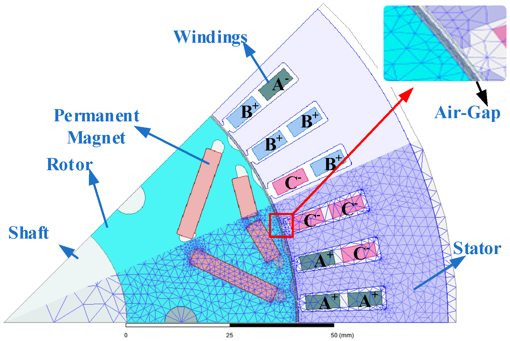
In this study, a distributed winding PMSM with 8 poles and 48 slots, as depicted in Figure 2, was selected as the prototype. A two-dimensional electromagnetic finite element model was constructed using the Ansys Maxwell software. Considering the symmetry of the prototype, only 1/8 of the model was used for the simulation in order to save computing resources. In addition, because the air gap is the location for energy conversion, the grid in the air-gap region was refined to improve the simulation accuracy. The geometric size parameters are given in Table 1.

3. Mathematical Modeling of the PMSM and Control System of Electric Vehicles Considering Non-Ideal Factors

3.1. Mathematical Equations for the Nonlinear Characteristics of the Inverter

The nonlinear characteristics of the inverter include the inherent characteristics of the switch devices and dead-time effect. To avoid a straight-through of the bridge arm, a delay td must be inserted into the drive signal, and the dead time is defined as
T d = t d + t o n t o f f + t P L H t P H L
where ton is the turn-on time, toff is the turn-off time, tPLH is the delay time of gate pulse rise propagation, and tPHL is the delay time of gate pulse drop propagation.
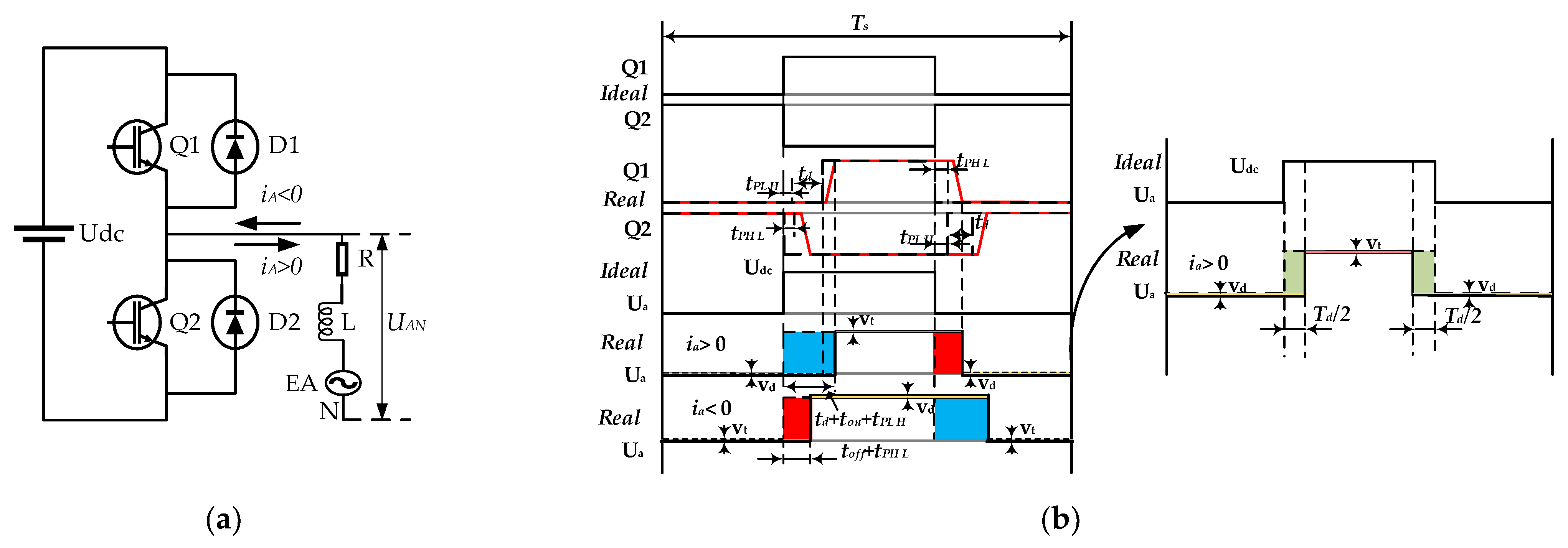
The current path of the A-phase bridge arm in the three-phase full-bridge inverter is illustrated in Figure 3a. During the dead time, when the A-phase current is positive, the phase current is continuous through the freewheeling diode D2, and the output voltage is positive; when the A-phase current is negative, the phase current is continuous through the freewheeling diode D1, and the output voltage is negative. In addition, when the switch is turned on, a conduction voltage drop occurs in the switch. When the switch is turned off, a conduction voltage drop occurs in the freewheeling diode, which leads to a large deviation between the actual voltage and the ideal voltage of the inverter output.
Figure 3b displays the error voltage waveform. The output voltage error is related to the DC bus voltage, the dead-time, and the conduction voltage drop. When the A-phase current is positive, the A-phase voltage error equation can be expressed as
Δ U A = Δ u × s g n ( i A )
where
Δ u = T d T s ( U d c + u t u d ) + u t + u d 2
s g n ( i A ) = { 1 i A < 0 1 i A > 0
Here, ut is the voltage drop of the switch and ud is the conduction voltage drop of the freewheeling diode. Through Fourier decomposition of the error voltage in a carrier period, the mathematical expression of the average error voltage can be obtained as follows:
Δ U A = 4 π Δ u ( c o s w t + 1 3 c o s 3 w t + 1 5 c o s 5 w t + 1 7 c o s 7 w t + ... )
Under the influence of the dead time and voltage drop, the output voltage of the inverter bridge arm is distorted, which results in odd harmonics, such as the 3rd, 5th, and 7th orders. Because the PMSM adopts a star connection, the 3rd and the multiples of the 3rd harmonic current cannot flow, and the 5th and 7th harmonics in the phase current are produced, causing stator flux distortion and torque fluctuation.

3.2. Mathematical Equations of the Nonsinusoidal Distribution of the Air-Gap Magnetic Field

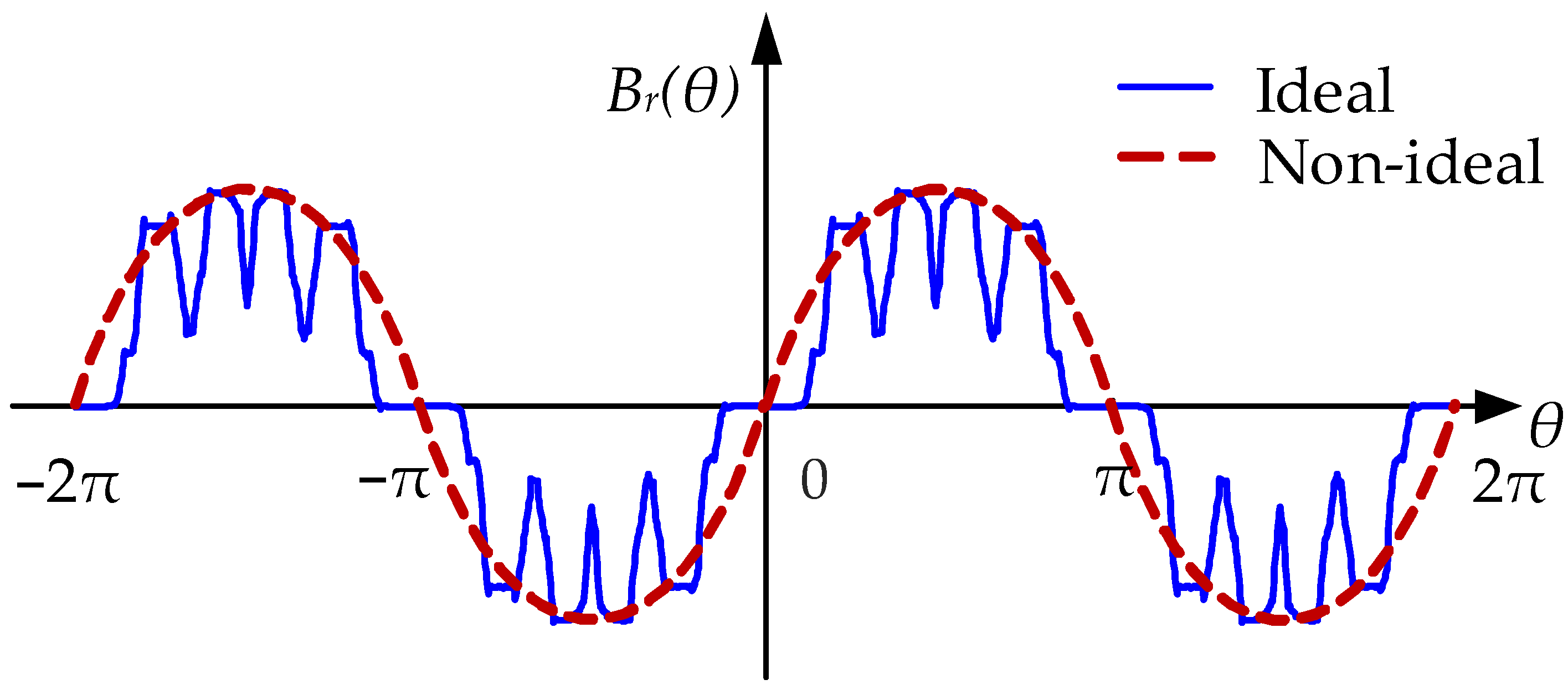
The conventional idealized modeling method for a PMSM assumes that the air-gap magnetic field has a sinusoidal distribution. However, owing to the influence of manufacturing and assembly errors, a large number of spatial harmonics are generated in the air-gap magnetic field, which distort the back electromotive force. The nonsinusoidal distribution of the air-gap magnetic field is shown in Figure 4.
The nonsinusoidal distribution of the magnetic field in the air gap can be decomposed into fundamental waves and harmonics that vary with the spatial position, which is expressed as a superposition of a series of sinusoidal waves. In the three-phase stationary coordinate system, the flux linkage generated by the permanent magnetic field in the A-phase winding of the stator can be described as follows:
ψ f a ( θ ) = k = 1 ψ 2 k 1 cos [ ( 2 k 1 ) θ + θ 2 k 1 ] = ψ 1 cos ( θ + θ 1 ) + ψ 3 cos ( 3 θ + θ 3 ) + ψ 5 cos ( 5 θ + θ 5 ) + ...
where ψ1 is the fundamental flux linkage of the magnet, while ψ3, ψ5, etc., are the amplitudes of the harmonic components of the flux linkage of the PM; θ is the rotor electrical angle. The flux linkage forms of the B- and C-phases of the PM magnetic field in the stator winding are the same as that of the A-phase, and the phase difference is 120°.
Through the Park and Clark transformation of the flux linkage generated by the magnetic field of the PM in the three-phase winding, the d- and q-axes flux expressions in the d–q coordinate system can be obtained as follows:
{ ψ d = L d i d + k = 1 { ψ 1 + [ ψ ( 6 k - 1 ) + ψ ( 6 k + 1 ) ] c o s ( 6 k θ + θ d 6 k ) } ψ q = L q i q + k = 1 { [ ψ ( 6 k - 1 ) + ψ ( 6 k + 1 ) ] s i n ( 6 k θ + θ q 6 k ) }
where Ld and Lq are the d- and q-axes inductances, respectively; id and iq are the d- and q-axes currents, respectively; and ψ6k±1 is the amplitude of the (6k ± 1) th PM flux linkage harmonics. The detailed derivation of (5) is described in Appendix A.
The existence of harmonics in the flux linkage distorts the back electromotive force in the stator winding. The back electromotive force of the stator windings in the d and q-axis coordinate system is [27]:
E d q = [ e d e q ] = [ w e L q i q w e k = 1 [ ( 6 k 1 ) ψ ( 6 k 1 ) + ( 6 k + 1 ) ψ ( 6 k + 1 ) ] s i n ( 6 k θ + θ d 6 k ) w e ( L d i d + ψ m ) + w e k = 1 [ ( 6 k 1 ) ψ ( 6 k 1 ) + ( 6 k + 1 ) ψ ( 6 + 1 ) ] c o s ( 6 k θ + θ q 6 k ) ]
where we is the rotor electrical angular velocity.
Under the influence of the air-gap magnetic field harmonics, the motor voltage balance equation can be expressed as:
{ u d = R s i d + L d d i d d t w e L q i q w e k = 1 { [ ( 6 k 1 ) ψ ( 6 k 1 ) + ( 6 k + 1 ) ψ ( 6 k + 1 ) ] s i n ( 6 k θ + θ d 6 k ) } u q = R s i q + L q d i q d t + w e L d i d + w e ψ m + w e k = 1 { [ ( 6 k 1 ) ψ ( 6 k 1 ) + ( 6 k + 1 ) ψ ( 6 k + 1 ) ] c o s ( 6 k θ + θ q 6 k ) }
where Rs is the stator resistance, we is the rotor electrical angular velocity, and ψm is the flux linkage of the PM.

3.3. Mathematical Equation of the Cogging Torque

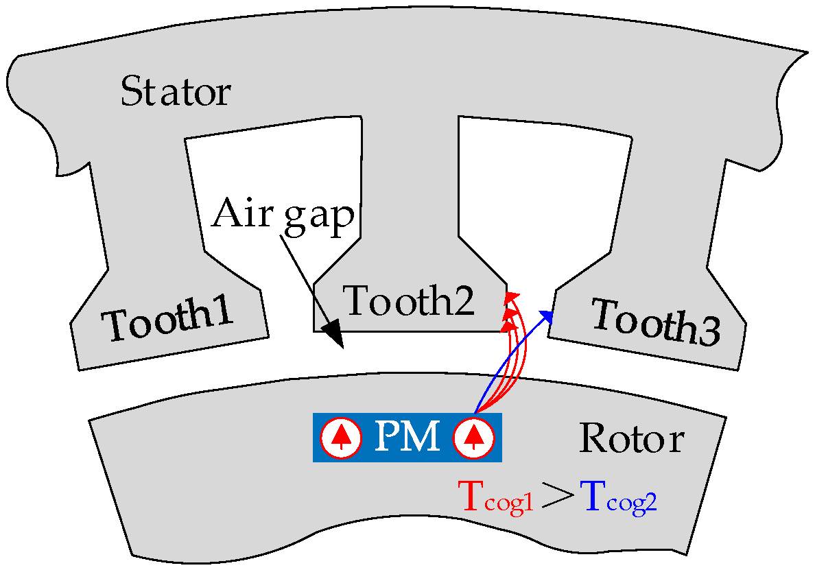
The cogging torque is a periodic torque generated by the self-adjustment trend between the motor rotor and the stator to the minimum reluctance position. The cogging torque is also generated in the case of no current in the PMSM. Figure 5 depicts a schematic of the cogging torque generation mechanism.
The cogging torque is caused by the tangential component of the interaction force between the stator tooth and the rotor and is related to the rotor position. The mathematical expression is given by the equation:
T c o g = n = 1 T n s i n ( n N c o w e t / P n + β n )
where Tn is the harmonic amplitude of each order, Pn is the polar logarithm, and Nco is the minimum common multiple of the number of stator slots and the number of rotor poles.
The time domain waveform of the tooth groove torque can be obtained through finite element analysis, and each parameter in the mathematical equation can then be calculated. A comparison of the cogging torque waveform obtained by finite element analysis and that calculated by the mathematical equation is presented in Figure 6.

3.4. Mathematical Equations of the Current Measurement Error

The current needs to be sampled during motor control. The mathematical relationship between the actual current and the sampling current can be expressed as
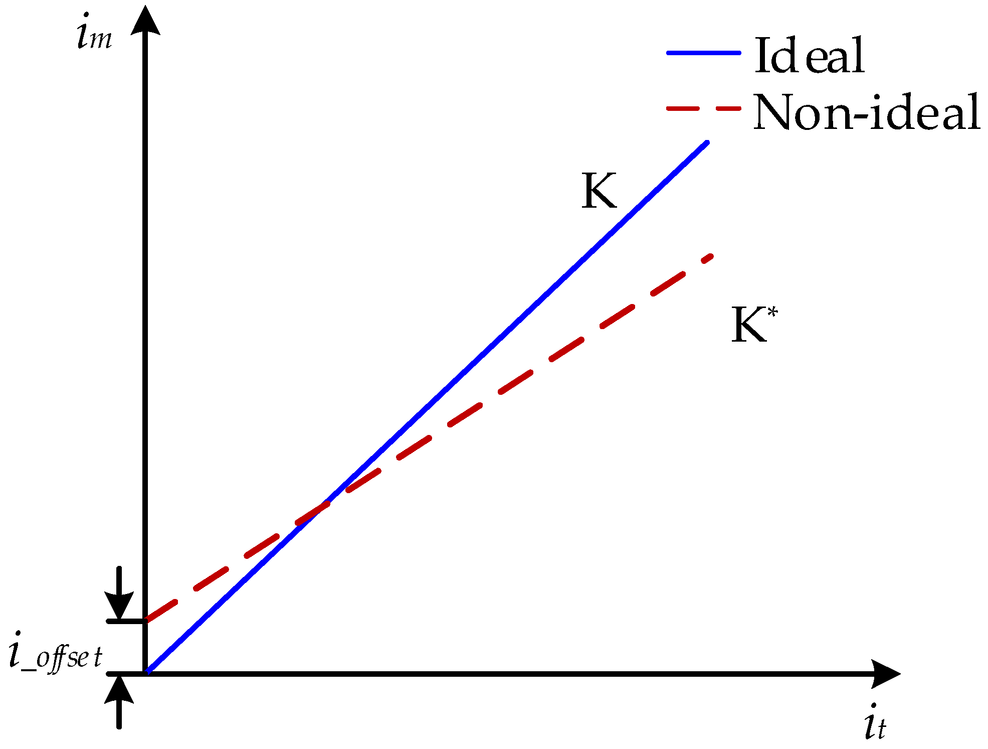
i m = K i t + i o f f s e t
where K is the proportional coefficient of the current sensor and ioffset is the offset amount, both of which are related to the resistance and offset voltage of the current sensor. In the process of current sampling, on the one hand, the proportionality coefficient is affected by the temperature, magnetic field, and other environmental factors. Thus, the value of the proportionality coefficient K deviates from 1, and a scaling error is generated. On the other hand, the DC offset error is caused by the zero drift of the power circuit components, namely the DC offset error. A schematic of the current measurement error is illustrated in Figure 7.
When only the current scaling error is considered, the DC offset error is zero, and the current error in the dq axis coordinate system can be calculated as
{ Δ i d s e = 3 3 ( K b K a ) I s i n ( 2 w e t + π 3 ) + 2 K b K a 2 I Δ i q s e = 3 3 ( K b K a ) I s i n ( 2 w e t + π 3 ) + 3 6 ( K a K b ) I
where Ka and Kb are the proportionality coefficients for measuring the A- and B-phase currents, respectively, while I is the amplitude of the phase current.
When only the current offset error is considered, Ka and Kb are 1. In the dq axis coordinate system, the current error is given by
{ Δ i d s e = 2 3 i a _ o f f s e t 2 + i a _ o f f s e t i b _ o f f s e t + i b _ o f f s e t 2 s i n ( w e t + α ) Δ i q s e = 2 3 i a _ o f f s e t 2 + i a _ o f f s e t i b _ o f f s e t + i b _ o f f s e t 2 c o s ( w e t + α ) α = t a n 1 ( 3 i a _ o f f s e t Δ i a _ o f f s e t + 2 i b _ o f f s e t )
where ia_offset and ib_offset are the current offset errors of the A- and B-phases. In the dq axis rotating coordinate system, the offset and scaling errors generate a harmonic current with frequencies of we and 2we, respectively, and cause torque fluctuation. The detailed derivation of (10) and (11) is described in Appendix B.

3.5. Mathematical Model of the PMSM Considering Non-Ideal Factors

In the process of simplifying the PMSM model, coordinate transformation needs to be performed to convert the electromagnetic parameters, such as the voltage, current, and flux linkage in different coordinate systems. In the synchronous rotating coordinate system, the dq axis mathematical model of the PMSM can be expressed as
{ U d = R i d + d φ d d t w e φ q U q = R i q + d φ q d t + w e φ d
{ φ d = L d i d + φ f φ q = L q i q
where id and iq are the currents of the stator in the d- and q-axes, respectively; Ud and Uq are the stator voltages in the d- and q-axes, respectively; Ld and Lq are the inductances in the d- and q-axes, respectively; R is the resistance of the stator winding; we is the electric angular velocity of the rotor; and φf is the flux linkage of the PM.
The electromagnetic torque equation of the PMSM can be expressed as
T e = 3 2 P n i q [ i d ( L d L q ) + φ f ]
where φf is the PM flux linkage, and Pn is the pole pair number.
The mechanical equation of motion is given by Equation (15).
d w m d t = 1 J ( T e T L ) B J w m
where wm is the mechanical angular speed, J is the rotational inertia, TL is the load torque, and B is the viscous friction coefficient.
Non-ideal factors cause a large number of harmonic components in the voltage, current, magnetic field, and back electromotive force, which make the air-gap magnetic field produce a series of time harmonics and spatial harmonics. In the dq axis coordinate system, the current measurement error is set as idm and iqm (m = 1, 2). The amplitudes of the 6kth harmonic current, caused by the nonlinearity of the inverter and the nonsinusoidal distribution of the air-gap magnetic field, are id6k and iq6k. Then, the d- and q-axes currents can be calculated as
{ i d h = i d 0 + i d 1 s i n ( θ + θ d 1 ) + i d 2 s i n ( 2 θ + θ d 2 ) + k = 1 i d 6 k s i n ( 6 θ + θ d 6 k ) i q h = i q 0 + i q 1 s i n ( θ + θ q 1 ) + i q 2 s i n ( 2 θ + θ q 2 ) + k = 1 i q 6 k c o s ( 6 θ + θ d 6 k )
where id0 and iq0 are the DC components of the d- and q-axes currents, respectively. The mathematical expression of the electromagnetic torque can be obtained by substituting Equations (5) and (16) into Equation (14), as follows:
T e = 3 2 P n ( ψ m i q h k = 1 { [ ψ ( 6 k 1 ) + ψ ( 6 k + 1 ) ] c o s ( 6 k θ + θ d 6 k ) } i d h + k = 1 { [ ψ ( 6 k 1 ) + ψ ( 6 k + 1 ) ] s i n ( 6 k θ + θ q 6 k ) } i q h + ( L d L q ) i d h i q h ) + n = 1 4 T n s i n ( 12 θ + β n ) = 3 2 P n ψ m ( i q 0 + i q 1 s i n θ + i q 2 s i n 2 θ + k = 1 i q 6 k c o s 6 θ ) T e , 0 , 1 , 2 , 6 n 3 2 P n k = 1 ψ d 6 k c o s 6 k θ ( i d 0 + i d 1 s i n θ + i d 2 s i n 2 θ + k = 1 i d 6 k s i n 6 θ ) T e , 4 , 5 , 7 , 8 , 6 n + 3 2 P n k = 1 ψ q 6 k s i n 6 k θ ( i q 0 + i q 1 s i n θ + i q 2 s i n 2 θ + k = 1 i q 6 k c o s 6 θ ) T e , 4 , 5 , 7 , 8 , 6 n + n = 1 4 T n s i n ( 12 θ + β n ) T e , 12 , 24 , 36 , 48 + 3 2 P n ( L d L q ) ( i d 0 + i d 1 s i n θ + i d 2 s i n 2 θ + k = 1 i d 6 k s i n 6 θ ) ( i q 0 + i q 1 s i n θ + i q 2 s i n 2 θ + k = 1 i q 6 k c o s 6 θ ) T e , 1 , 2 , 4 , 5 , 7 , 8 , 6 n
It can be seen from (17) that there are multiple orders of torque ripple, such as 4th, 5th, and 7th, in the electromagnetic torque. The PM torque of the PMSM contains both a constant component and a ripple component. Moreover, what should be addressed is that the d and q-axis current harmonics will introduce the PM torque ripple by interacting with the PM flux harmonics, and the interaction of the d and q-axis current harmonics will also introduce the reluctance torque ripple, which is quite different from the traditional d and q-axis model.

4. Simulation Analysis of the Dynamic Characteristics of the PMSM for Electric Vehicles under Different Speed–Load Conditions

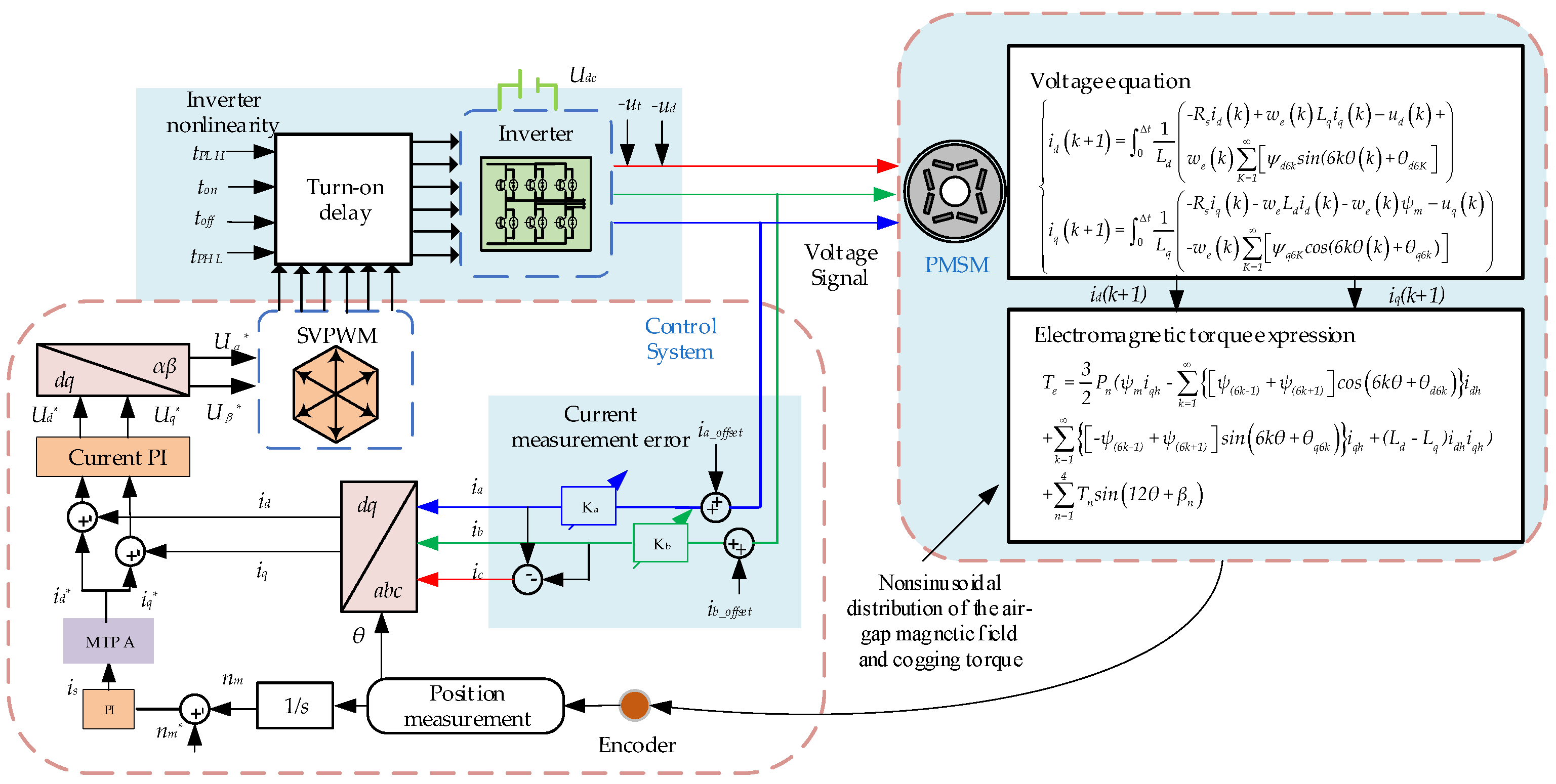
Based on the mathematical model of the PMSM considering non-ideal factors, a dynamic model of the PMSM and its control system was established in the Simulink/Matlab platform to simulate the dynamic operation process of the PMSM. The schematic of the PMSM and its control system model considering non-ideal factors is displayed in Figure 8.
In this section, the influence law of single factors, such as the inverter nonlinear characteristics, the nonsinusoidal distribution of the air-gap magnetic field, the cogging torque, and the current measurement error, as well as the combined effect of the non-ideal factors on the dynamic characteristics of the PMSM current, flux linkage, and torque were compared and analyzed. The main parameters of the motor are listed in Table 2.

4.1. Influence of SVPWM on the PMSM

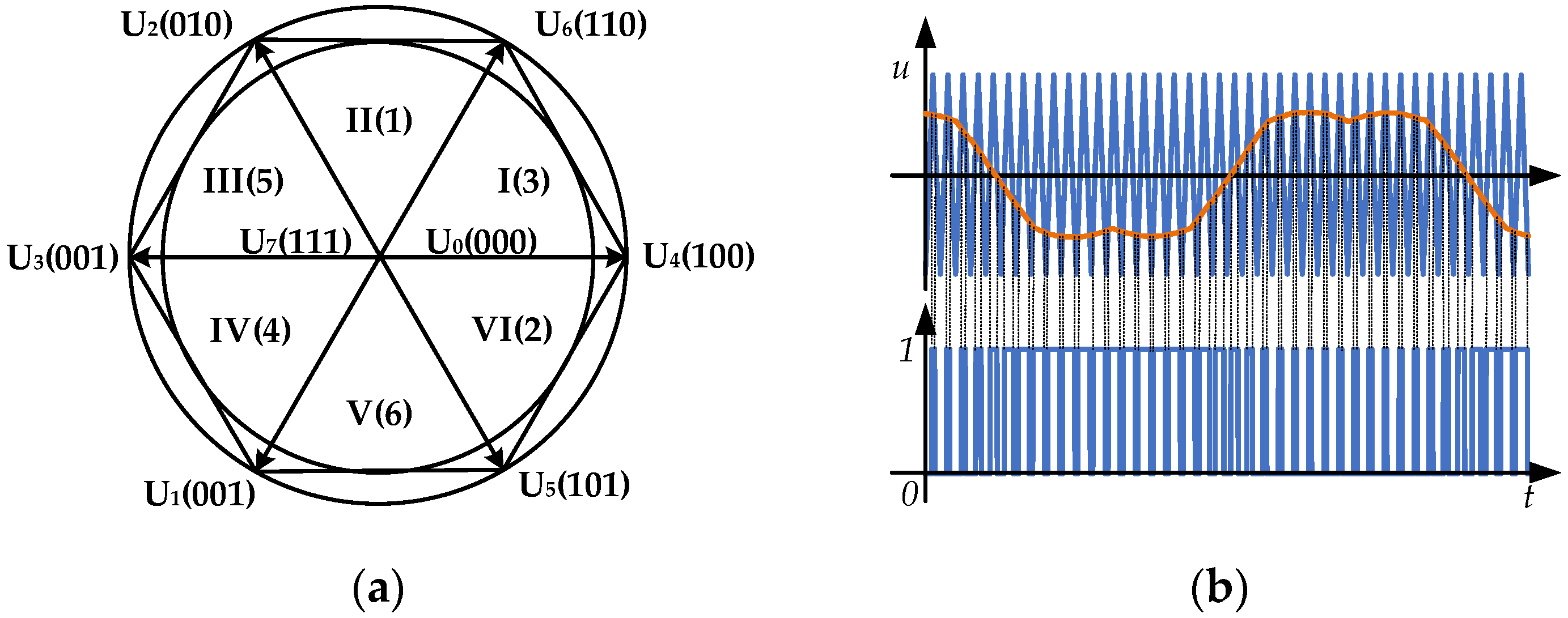
The ideal motor model considers only the voltage error caused by SVPWM. The SVPWM is based on the average equivalent principle, and the given voltage vector is linearly synthesized by the basic voltage vector in the modulation period. Six nonzero voltage vectors divide the circular plane into six sectors, as shown in Figure 9a. Piecewise approximation of the voltage vector produces current harmonics and torque ripples. The principle of the SVPWM trigger pulse is depicted in Figure 9b.
The Fourier series expansion of the line voltage output by the inverter can be expressed as
F ( t ) = A 00 2 + k = 1 ( A 0 k cos k w r t + B 0 k sin k w c t ) + n = 1 ( A n 0 cos n w c t + B n 0 sin w c t ) + n = 1 k = ± 1 ± [ A k n cos ( k w r t + n w c t ) + B k n sin ( k w r t + n w c t ) ]
where wr is the modulated wave frequency, and wc is the carrier frequency.
To reflect the degree of waveform distortion, a harmonic distortion rate is introduced:
THD = n = 2 ( I n I 1 ) 2
where In and I1 are the amplitudes of the harmonics and the fundamental current, respectively.
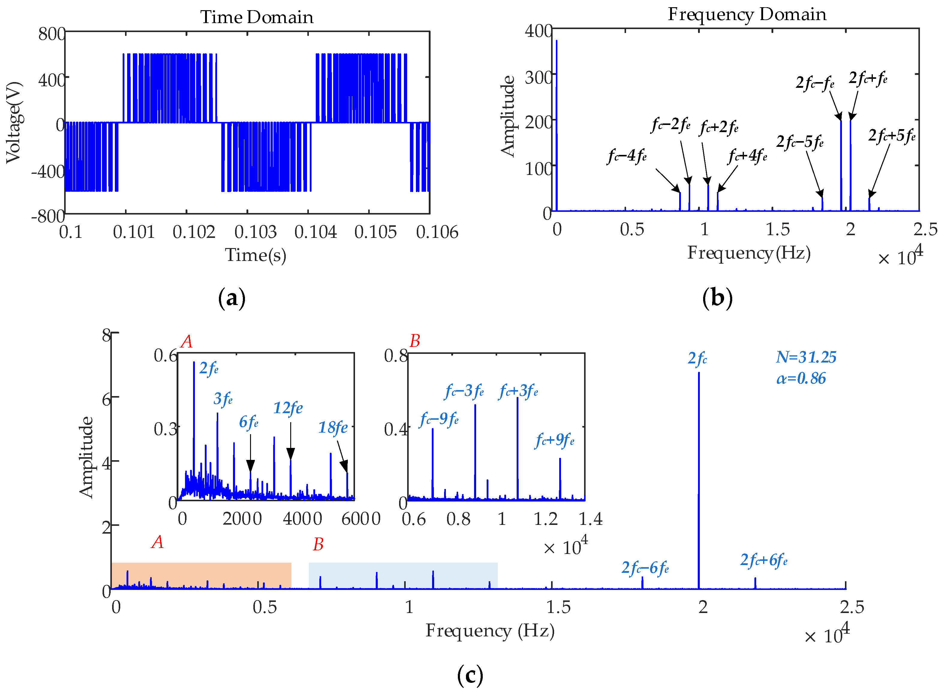
From Equation (16), it can be observed that the fundamental frequency, as well as the switching frequency and its integer multiples of harmonics and surrounding side band harmonics, exists in the output voltage. The harmonic amplitude is related to the modulation ratio N and the carrier ratio α. Figure 10a,b shows the time domain and the frequency domain result of the inverter output voltage under the rated conditions (speed of 4800 rpm and load of 153 Nm) and the fundamental frequency fe of 320 Hz. In the low-frequency region, the output voltage contains the fundamental frequency and its integer harmonics. In the high-frequency region, the output voltage is composed of the switching frequency (10 kHz) and the integer harmonics. An edge band exists around the switching frequency, modulated by the fundamental frequency. Figure 10c displays the frequency domain of the electromagnetic torque; there are also fluctuating orders of electromagnetic torque near the low frequency and switching frequency.

4.2. Consideration of the Nonlinear Characteristics of the Inverter

4.2.1. Constant Speed, Constant Load Condition

The nonlinear characteristics of the inverter cause a large number of harmonic components in the phase current, which result in the distortion of the stator flux linkage and the existence of the time harmonic magnetic field in the motor air gap. The amplitudes of the current harmonic are related to dead time, voltage drop, carrier frequency, and the magnitude of the DC side voltage. In this study, by setting the dead time and voltage drop of the inverter, the influences of the nonlinear characteristics of the inverter on the dynamic characteristics of the motor current and electromagnetic torque were analyzed. The inverter parameters are listed in Table 3.
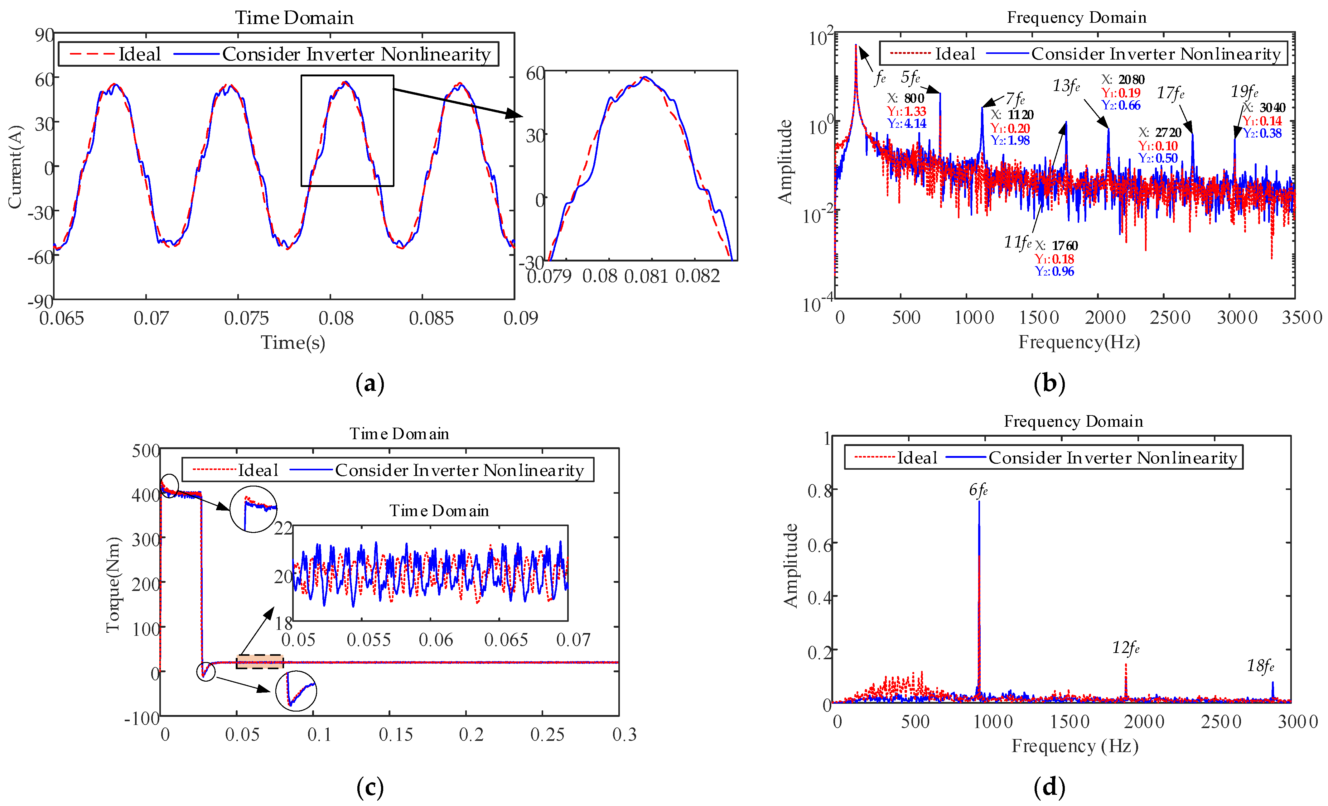
The time and frequency domain simulation results of the motor current and electromagnetic torque at 2400 rpm speed and 20 N·m load considering the nonlinear characteristics of the inverter are shown in Figure 11.
The time and frequency domain diagrams of the A-phase current are displayed in Figure 11a,b, respectively. After considering the nonlinear characteristics of the inverter, the phase-current waveform of the motor is obviously distorted, and the fundamental frequency fe of the phase current is 160 Hz. There are noticeable 5th and 7th odd harmonic components in the frequency domain of the phase current, and the amplitude of the high-order harmonic current is small. From the electromagnetic torque Equation (15), it can be seen that the existence of the harmonic components of the phase current causes fluctuations in the electromagnetic torque. Figure 11c,d show the time and frequency domain diagrams of the electromagnetic torque, respectively. The electromagnetic torque fluctuates significantly, and there are 6nth order fluctuation components in the frequency domain diagram, which verifies the theoretical analysis of the nonlinear characteristics of the inverter. Therefore, the nonlinear characteristics of the inverter cause the motor to produce 6k − 1 and 6k + 1 (k = 1, 2, 3 …) order harmonic currents and 6nth (n = 1, 2, 3 …) order torque fluctuations.

4.2.2. Different Speeds, Constant Load Condition

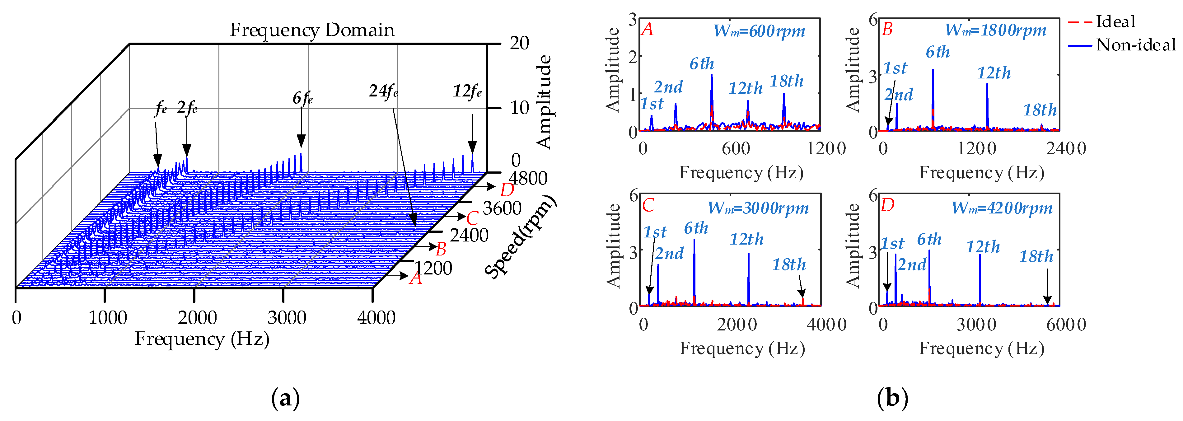
The waterfall diagram of the frequency domain characteristics varying with the rotational speed under a speed step of 100 rpm and constant load of 153 N·m is depicted in Figure 12a. Figure 12b illustrates the frequency domain comparison results of the electromagnetic torque under the four operating conditions.
In the low-speed region, the amplitude of the torque ripple is small, indicating that the motor control system can effectively regulate the low-frequency torque ripple. The amplitude of the torque ripple is large in the middle- and high-speed regions; the 6th order torque ripple component is dominant, and the contributions of the 12th and 18th order torque ripple components are small. With an increase in speed, the amplitude of the 12th order torque fluctuation first increases and then decreases owing to the interaction between the voltage error caused by SVPWM and the harmonic current caused by the nonlinear characteristics of the inverter.

4.2.3. Different Loads, Constant Speed Condition

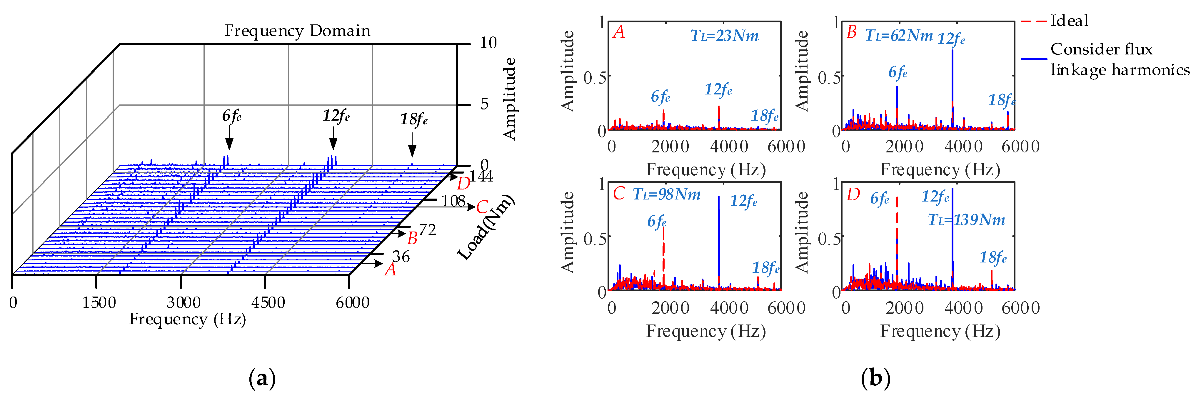
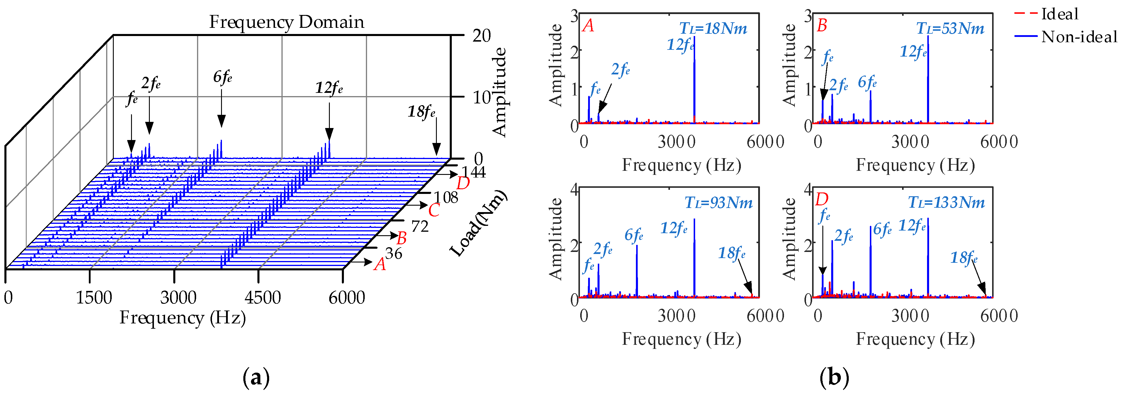
The frequency domain of the electromagnetic torque under different loads with a load step of 5 N·m and a constant speed of 4800 rpm is displayed in Figure 13a. Figure 13b shows a comparison of the frequency domain results of the electromagnetic torque. With an increase in load, the current amplitude increases, and the distorted flux linkage interacts with the current. The amplitude of each order of torque fluctuation increases and the 6th order fluctuation frequency is the dominant frequency. The last part of expression (17) can explain the amplitude of the torque fluctuation rises with an increase in load.
T e = ... + 3 2 P n ( L d L q ) ( i d 0 + i d 1 s i n θ + i d 2 s i n 2 θ + k = 1 i d 6 k s i n 6 θ ) ( i q 0 + i q 1 s i n θ + i q 2 s i n 2 θ + k = 1 i q 6 k c o s 6 θ ) T e , 1 , 2 , 4 , 5 , 7 , 8 , 6 n
Although the current harmonic amplitude caused by the inverter nonlinearity is almost unaffected by the load, the DC component of the d and q-axis increases with an increase in load. It can be concluded from the formula that the interaction between the increases of the DC component and the current harmonic component causes the fluctuation of the reluctance torque to increase.

4.3. Consideration of the Nonsinusoidal Distribution of the Air-Gap Magnetic Field

4.3.1. Constant Speed, Constant Load Condition

The nonsinusoidal distribution of the air-gap magnetic field leads to the distortion of the rotor flux and the back electromotive force, which generates the space harmonic magnetic field in the air gap and the harmonic current in the winding. The harmonic content of each order of the PM flux linkage and its ratio to the fundamental wave are listed in Table 4. Because the effect of the higher-order flux harmonics is smaller, this study analyzes the influence law of the nonsinusoidal distribution of the air-gap magnetic field on the motor by introducing the 5th, 7th, and other flux harmonics.
After considering the nonsinusoidal distribution of the air-gap magnetic field, the time and frequency domains of the motor current and electromagnetic torque under 4800 rpm and 153 N·m were determined, as depicted in Figure 14.
Figure 14a,b illustrates the time and frequency domains of the A-phase current. The fundamental frequency fe of the phase current is 320 Hz, and the waveform of the A-phase current is almost sinusoidal with a small distortion. There are 6k − 1 and 6k + 1 current harmonics caused by the back electromotive force distortion in the frequency domain. The time and frequency domains of the electromagnetic torque are displayed in Figure 14c,d, respectively. The electromagnetic torque is affected by the spatial harmonics and back electromotive force distortion, which causes the 6nth order fluctuation. Therefore, the nonsinusoidal distribution of the air-gap magnetic field causes the existence of spatial harmonics in the air-gap magnetic field of the motor and counter electromotive force harmonics in the stator winding, which leads to the 6nth order fluctuation of the torque.

4.3.2. Different Speeds, Constant Load Condition

The waterfall diagram of the frequency domain characteristics varying with the rotational speed under a speed step of 100 rpm and constant load of 153 N·m is shown in Figure 15a. Figure 15b depicts the frequency domain comparison results of the electromagnetic torque under four operating conditions. In the low-speed region, the torque fluctuation amplitude is small, which indicates that the motor control system is effective in regulating the low-frequency torque fluctuation. The amplitude of each order of torque fluctuation component in the mid-speed region is similar, which demonstrates that the PI regulator (PI controller in motor closed-loop control system) effectively suppresses the harmonic amplitude caused by the back electromotive force. Under partial speed conditions, the peak frequency shifts to a high frequency because of the interaction between the voltage harmonics generated by the SVPWM and the back electromotive force harmonics, indicating that the harmonic currents generated by both are not linearly superimposed when acting together. With an increase in rotational speed, the harmonic amplitude of the back electromotive force increases, and the amplitude of each order of torque fluctuation component generally increases. This phenomenon shows that the current harmonic suppression effect of the PI regulator becomes worse, and its electromagnetic torque fluctuation is more violent when the motor is running under high-speed conditions.

4.3.3. Different Loads, Constant Speed Condition

Figure 16 shows the frequency domain results of the electromagnetic torque under different loads and a constant speed of 4800 rpm. As the load increases, the distorted PM flux linkage interacts with the stator flux linkage, resulting in an increasing trend of each order component in the electromagnetic torque, and the 12th order fluctuation component is dominant. Therefore, the higher the external load, the greater the amplitude of the electromagnetic torque vibration caused by the nonsinusoidal distribution of the air-gap magnetic field.

4.4. Consideration of the Cogging Torque

4.4.1. Constant Speed, Constant Load Condition

The influence of the cogging torque on the accuracy of the motor and control system was determined by introducing mathematical equations. The parameters are listed in Table 5.
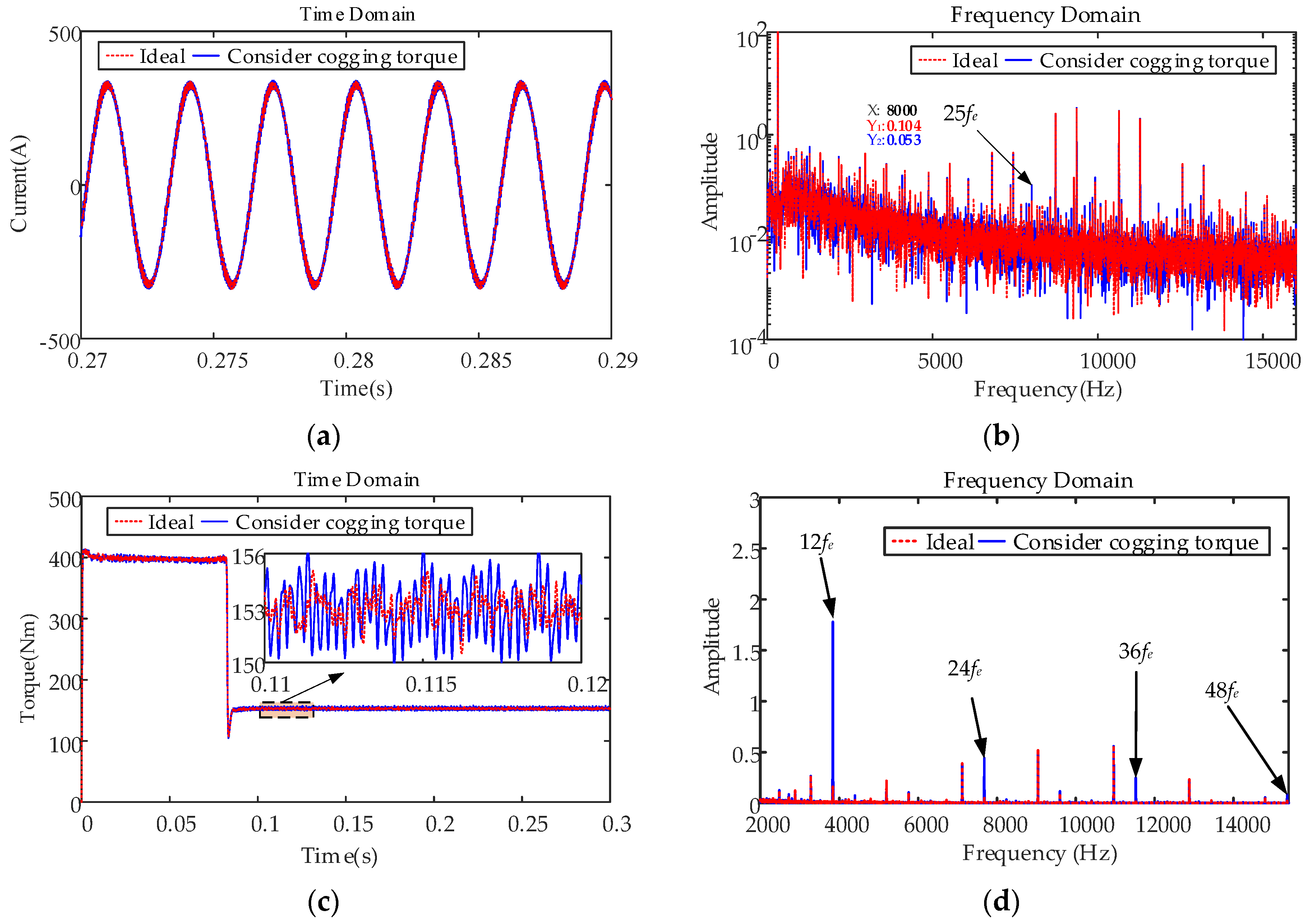
After considering the cogging torque, the time and frequency domains of the motor current and electromagnetic torque under 4800 rpm and 153 N·m load were determined, as illustrated in Figure 17.
Considering the cogging torque, the harmonic amplitude of the current waveform in the time domain is essentially the same, and only the 25th harmonic current amplitude increases, indicating that the motor control system has little influence on the cogging torque under the rated condition. There is a clear 12th order torque ripple in the electromagnetic torque.

4.4.2. Different Speeds, Constant Load Condition

Figure 18 displays the frequency domain results of the electromagnetic torque under different speeds and a constant load of 153 N·m. At low speeds, the 12th order torque ripple amplitude is small, showing that the motor control system can effectively regulate the cogging torque. However, with an increase in speed, especially in the high-speed region, the amplitude of the torque ripple is large, and the control system has little influence on the cogging torque.
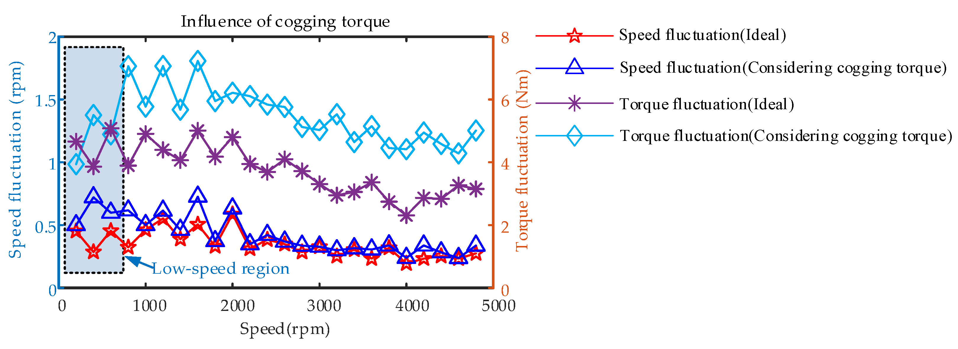
Figure 19 shows the comparison results of speed and torque fluctuations at different speeds for the ideal and after considering cogging torque.
After considering the cogging torque, the fluctuation amplitude of the electromagnetic torque in the mid-speed region is relatively large, and the fluctuation amplitude of the motor shaft speed in the low-speed region is large, which indicates that the presence of the cogging torque affects the low-speed performance of the motor speed control system.

4.4.3. Different Loads, Constant Speed Condition

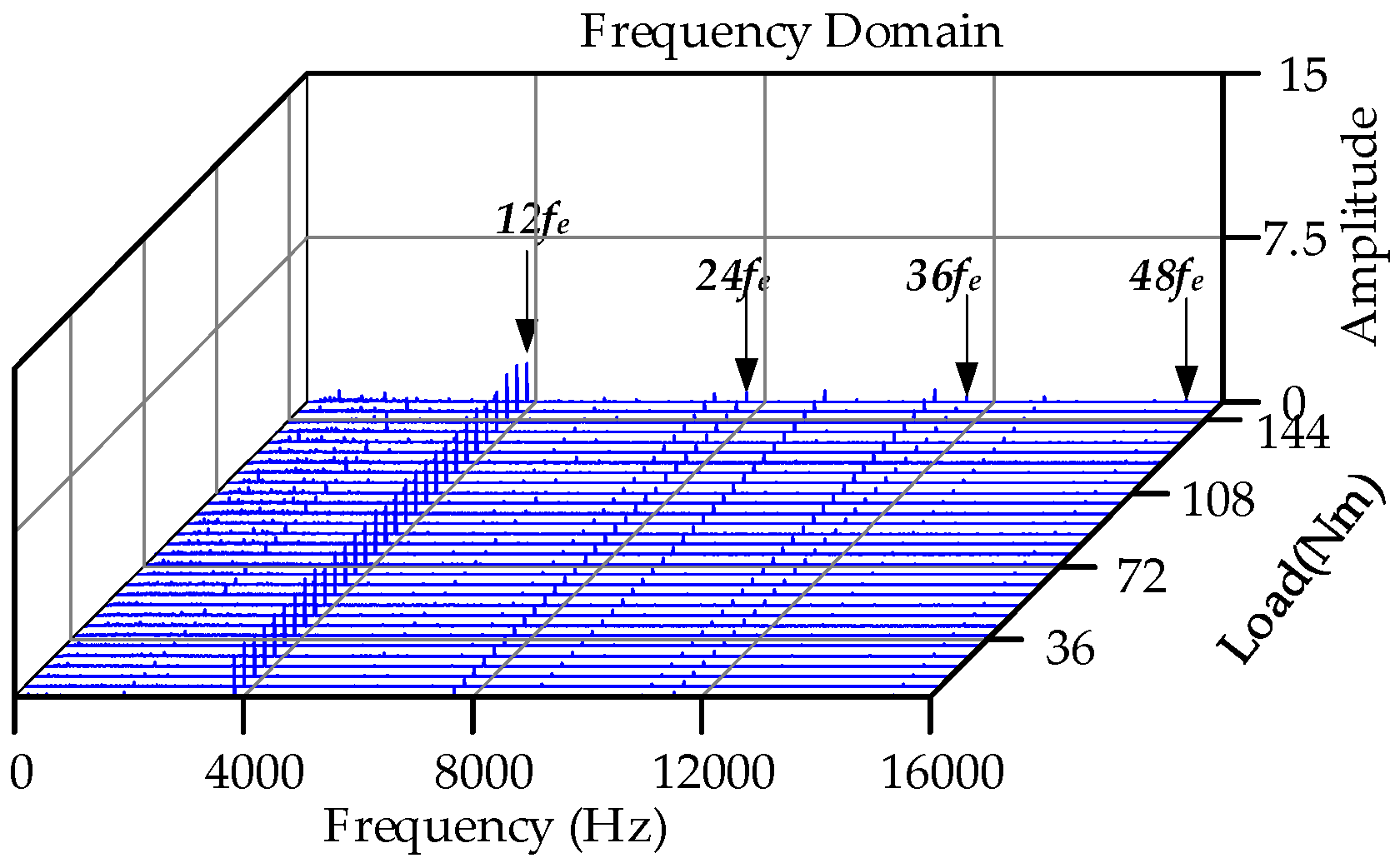
Figure 20 shows the waterfall diagram of the electromagnetic torque under different loads and a constant speed of 4800 rpm. It can be observed that in the full load range, the amplitude of the torque ripple is almost unchanged, and the influence of the cogging torque is consistent under various loads.

4.5. Consideration of the Current Measurement Error

4.5.1. Constant Speed, Constant Load Condition

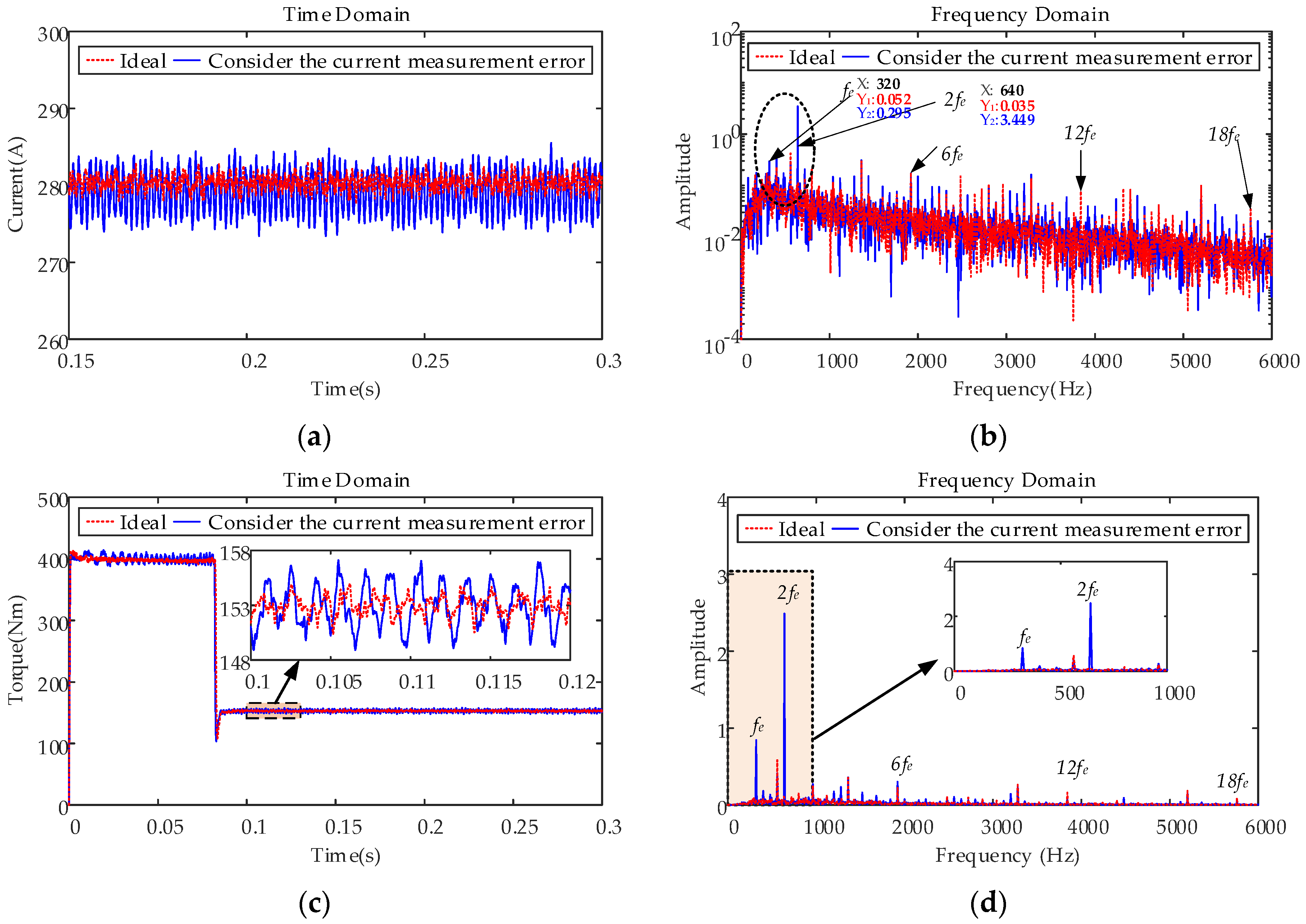
The degree of current distortion caused by the current measurement error is related to the scale factor and offset error. The sensor proportional coefficients Ka and Kb are 1.01 and 0.98, respectively, and the offset errors ia_offset and ib_offset are 1 A and −0.6 A, respectively. Figure 21 depicts the time domain of the d- and q-axes currents, the frequency domain of the q-axis current, and time and frequency domains of the electromagnetic torque after the current measurement error is introduced under the conditions of 4800 rpm motor speed and 153 N·m load.
The time and frequency domains of the q-axis current are illustrated in Figure 21a,b, respectively. The d- and q-axes currents fluctuate significantly, and 1st and 2nd order harmonics exist in the frequency domain of the q-axis current. Figure 21c,d displays the time and frequency domains of the electromagnetic torque, respectively. There exist 1st and 2nd order low-frequency fluctuation components in the electromagnetic torque, which are caused by the 1st and 2nd order current harmonic components in the d- and q-axes currents.

4.5.2. Different Speeds, Constant Load Condition

Figure 22 shows the frequency domain results of the electromagnetic torque under different speeds and a constant load of 153 N·m. With an increase in rotational speed, the amplitude of each order of torque fluctuation component exhibits an increasing trend. This indicates that the higher the frequency of the 1st and 2nd current harmonics in the d- and q-axes caused by the current measurement error, the greater the disturbance to the control performance of the motor control system, which leads to an increase in the amplitude of torque fluctuation. Therefore, the low-frequency electromagnetic torque vibration caused by the current measurement error should be fully considered under high-speed operating conditions.

4.5.3. Different Loads, Constant Speed Condition

Figure 23a,b depicts the waterfall diagram of the electromagnetic torque and frequency domain comparison results under different loads and a constant speed of 4800 rpm. With an increase in load, the amplitude of the 2nd order torque fluctuation in the electromagnetic torque increases significantly, while the amplitude of the 1st order torque fluctuation remains unchanged owing to the increase in the 3-phase current amplitude, which causes an increase in the current measurement scaling error and the 2nd order torque fluctuation.

4.6. Consideration of the Nonlinear Characteristics of the Inverter, Nonsinusoidal Distribution of the Air-Gap Magnetic Field, and Current Measurement Error

In the actual operation of PMSMs, the nonlinear characteristics of the inverter, the nonsinusoidal distribution of the air-gap magnetic field, and the current measurement errors exist simultaneously; therefore, the non-ideal factors need to be considered comprehensively to analyze their effects on the nonlinear dynamic characteristics of the motor.

4.6.1. Constant Speed, Constant Load Condition

The time and frequency domain comparison results of the A-phase current and electromagnetic torque under 4800 rpm speed and 153 N·m load are displayed in Figure 24.
The time and frequency domains of the A-phase current are shown in Figure 24a,b, respectively. The fundamental frequency fe of the phase current is 320 Hz, and 2nd, 3rd, 6k − 1th, and 6k + 1th harmonics exist in the A-phase current. The 2nd and 3rd harmonics are caused by current measurement errors, whereas the 3rd harmonic is due to the disturbance of the current loop in the control system owing to the current measurement error, which leads to the three-phase current asymmetry of the stator winding of the motor. Therefore, it still exists in PMSMs with Y-type coupling. The 6k − 1th and 6k + 1th harmonics are caused by the combination of the nonlinear characteristics of the inverter and the nonsinusoidal distribution of the air-gap magnetic field. Figure 24c,d depicts the time and frequency domains of the electromagnetic torque, respectively. There exist 1st, 2nd, and 6nth order fluctuations of the electromagnetic torque, among which, the 1st and 2nd order torque fluctuations are due to current measurement errors; the 6nth order torque fluctuations are jointly caused by the nonlinear characteristics of the inverter and the nonsinusoidal distribution of the air-gap magnetic field, and the 12nth order torque fluctuations are caused by the cogging torque. Additionally, there are obvious 4th, 5th, and 8th order torque ripples, which verify the electromagnetic torque analytical expression (17). In addition, in the frequency domain of the electromagnetic torque, there exist sidebands with the 1st, 2nd, and 6nth orders as the carrier frequency and rotation frequency or frequency multiplication of the motor as the modulation frequency, which further aggravate the vibration amplitude, and the rotational frequency fm of the motor is 80 Hz. In the frequency domain of the phase current, corresponding frequency information exists, showing that the electrical system is affected by electromagnetic vibration, which increases the harmonic distortion rate. The detailed data comparison of the current harmonics and fluctuation amplitude of the motor torque and the speed before and after considering the non-ideal factors are shown in Table 6. The simulation results show that the amplitude of the current harmonics and the fluctuation of speed and torque obviously increase after considering the non-ideal factors.
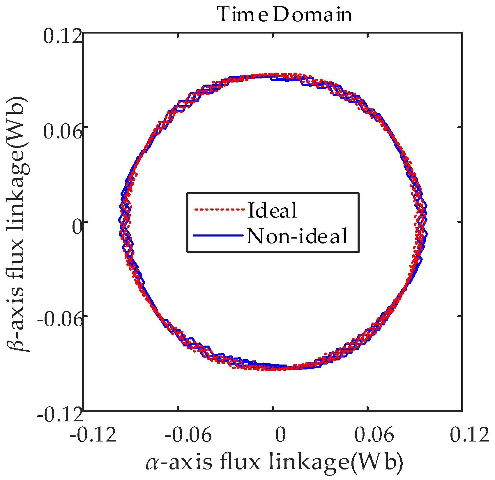
A comparison of the results for the flux linkage trajectory is shown in Figure 25. There is an obvious pulsation in the trajectory of the non-ideal flux linkage, which indicates that the current vector fluctuation causes the flux linkage trajectory pulsation, leading to torque fluctuation.
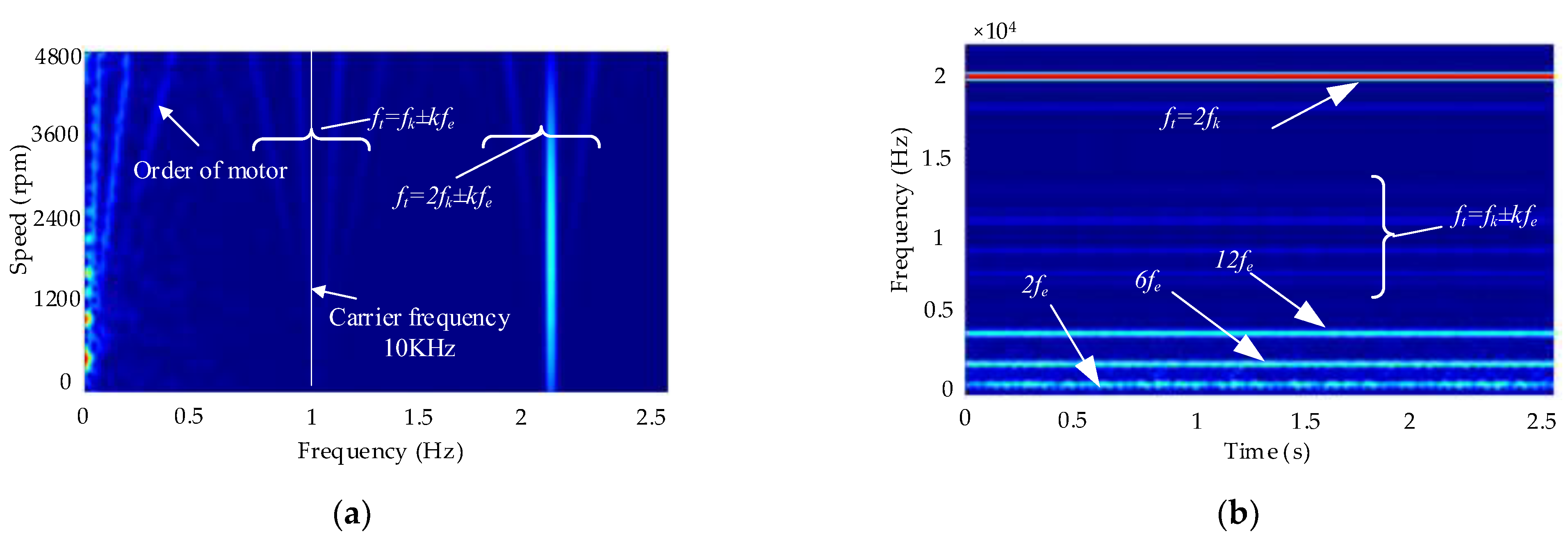
Figure 26a displays the color map of the electromagnetic torque. The 1st, 2nd, and 6nth orders of the starting point are the unilateral scattering of the zero point caused by the non-ideal factors of the motor structure and controller. The umbrella order of the deviation from the zero point near the 10 and 20 kHz frequency is caused by the SVPWM, which is the result of the signal modulation. The time-frequency domain of the mechanical angular acceleration of the motor is shown in Figure 26b. The amplitude corresponding to the 20 kHz frequency is the largest, and the amplitude corresponding to 1920 Hz is the second; the high-frequency torsional vibration causes large noise and easily leads to shaft deformation and fatigue.
Owing to the non-ideal factors, such as the motor structure, magnetic field design, controller signal error, and delay, a large number of harmonic currents exist in the motor winding, resulting in an obvious torque ripple order proportional to the motor speed in the electromagnetic torque. At some speeds, the torque ripple causes resonance of the entire machine, leading to high-frequency screams. In some low-speed starting conditions, longitudinal jitter of the vehicle occurs, and the subjective driving experience of the driver is significantly reduced. Simultaneously, the harmonic current causes additional electromagnetic loss, reduces the operation efficiency of the motor, increases its temperature, reduces its control accuracy, and further deteriorates its vibration state.

4.6.2. Different Speeds, Constant Load Condition

The waterfall diagram of the frequency domain characteristics varying with the rotational speed under a speed step of 100 rpm and constant load of 153 N·m is depicted in Figure 27a. Figure 27b displays the frequency domain comparison results of the electromagnetic torque under the four operating conditions. Under different speeds, the electromagnetic torque fluctuates significantly after introducing the non-ideal factors, among which the 6th order torque fluctuation component dominates. With an increase in speed, the amplitude of each order of torque fluctuation component generally tends to rise because of the poor effect of the motor control system on the fluctuation component shifted to high frequency, the increase in the harmonic amplitude of the back electromotive force, and the SVPWM error.

4.6.3. Different Loads, Constant Speed Condition

Figure 28 shows the frequency domain results of the electromagnetic torque under different loads and a constant speed of 4800 rpm. As the load increases, the amplitude of the 1st order torque fluctuation remains unchanged, whereas the torque fluctuation components of other orders increase. This indicates that the amplitude of the torque fluctuation caused by the current offset error remains unchanged, and the amplitude of the torque fluctuation caused by the air-gap magnetic field nonsinusoidal distribution and the current scaling error increases. Therefore, the nonlinear characteristics of the inverter, the nonsinusoidal distribution of the air-gap magnetic field, and the current measurement error lead to a sharp deterioration in the vibration state of the motor when it is operated under high-speed and heavy-load conditions.

4.6.4. Comparison of the Degree of Influence of Each Factor

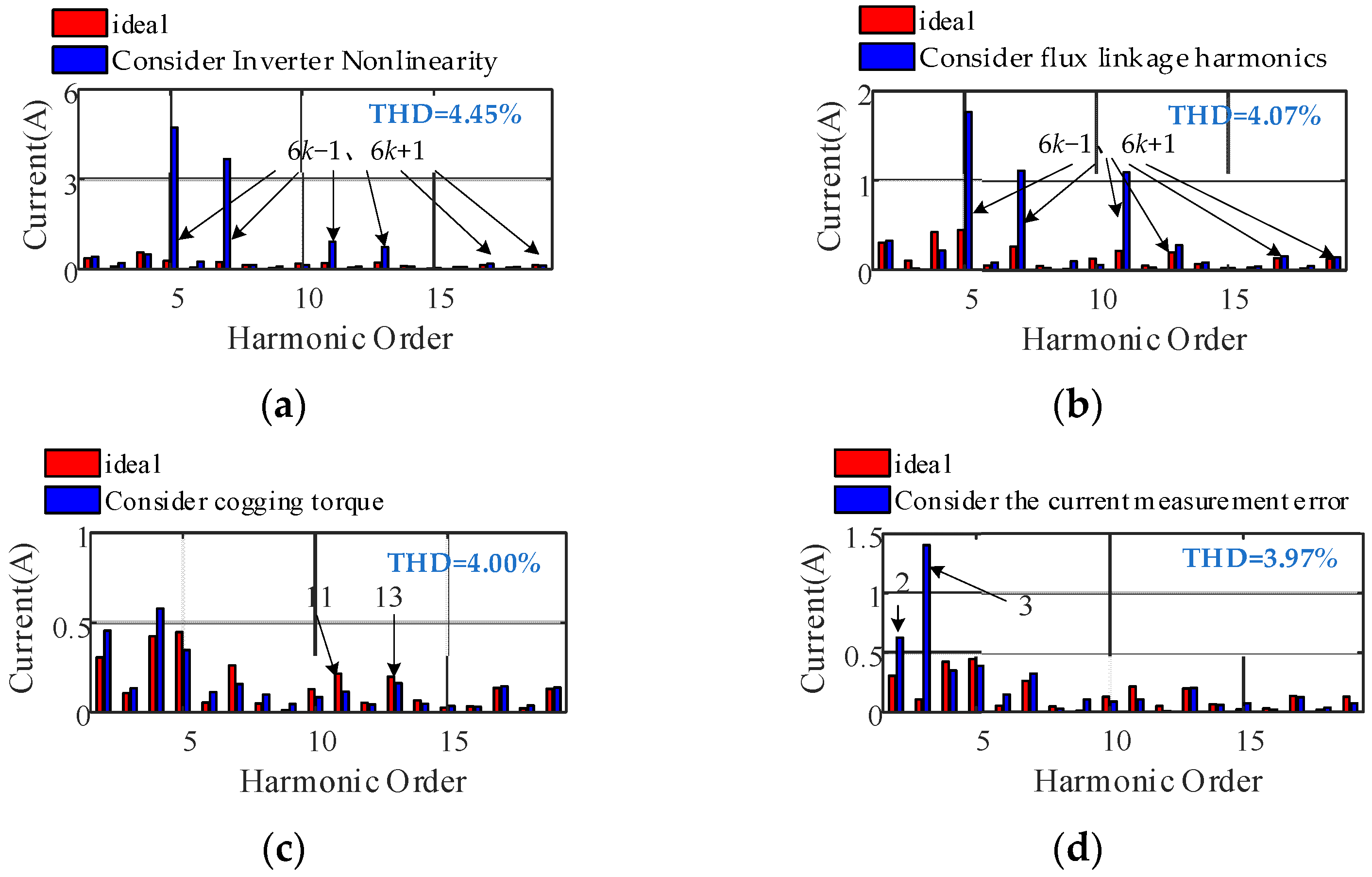
Figure 29a–d depicts the frequency spectra of the phase current considering the inverter nonlinearity, the nonsinusoidal distribution of the air-gap magnetic field, the cogging torque, and the current measurement error under the operating conditions of 4800 rpm speed and 153 N·m load, respectively. The inverter nonlinearity and magnetic field harmonics mainly cause the 6k − 1th and 6k + 1th harmonic amplitudes in the current to increase significantly, but the inverter nonlinearity leads to a more evident current distortion. After considering the inverter nonlinearity, the phase current distortion rate is 4.45%, and after considering the nonsinusoidal distribution of the air-gap magnetic field, the phase current distortion rate becomes 4.07%. The cogging torque has little effect on current harmonics. The current measurement error mainly causes an obvious increase in the 2nd and 3rd harmonic amplitudes of the current, and the current distortion rate is 3.97%. Considering the non-ideal factors comprehensively, the phase current distortion rate is 4.59%, showing that the harmonic amplitudes of each order are nonlinear superpositions when the non-ideal factors work together.
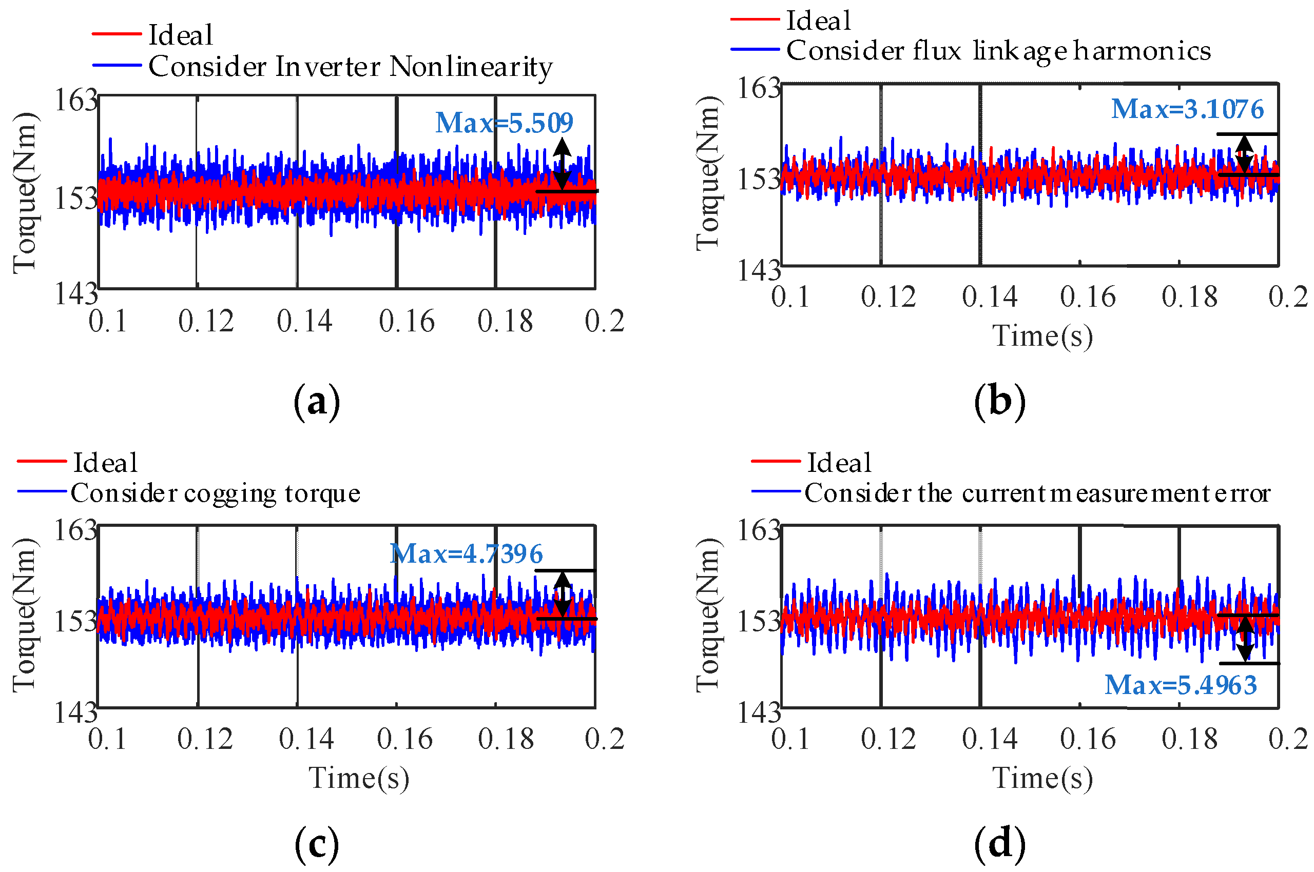
Figure 30a–d displays the time domain diagrams of the electromagnetic torque considering the inverter nonlinearity, the nonsinusoidal distribution of the air-gap magnetic field, the cogging torque, and the current measurement error under the operating conditions of 4800 rpm speed and 153 N·m load, respectively. The peak torque fluctuations caused by each single factor are 5.509, 3.1076, 4.7396, and 5.4963, respectively. The peak torque fluctuations after comprehensive consideration of the non-ideal factors are 10.3692. It is shown that the nonlinearity of the inverter has the greatest impact on the torque ripple under the rated conditions, and the current measurement error has the second highest impact on the torque ripple. In contrast, the nonsinusoidal distribution of the air-gap magnetic field has the smallest impact on the torque ripple. This is because the structural optimization of the PMSM for the electric vehicles considered in this study is excellent, resulting in smaller harmonic components of the magnetic field.

5. Discussion

In this study, to determine the influence of non-ideal factors such as the inverter nonlinearity, the nonsinusoidal distribution of the air-gap magnetic field, the current measurement error, and the cogging torque on the dynamic and vibration characteristics of the PMSM, a double closed-loop PMSM model considering the non-ideal factors is established. Based on the analysis of the simulation results, it is concluded that the inverter nonlinearity and nonsinusoidal distribution of the air-gap magnetic field lead to a 6nth order torque fluctuation of the motor electromagnetic torque, and the coupling effect of the two aggravate the 6nth order torque fluctuation. The current measurement error causes the 1st and 2nd order torque fluctuations of the electromagnetic torque, while the cogging torque produces the 12nth order torque fluctuation. The non-ideal factors and shaft frequency modulation of the motor cause multi-order torque ripples in the electromagnetic torque, and the vibration state of the motor deteriorates sharply under high-speed and heavy-load conditions.
Most of the existing studies have ideally simplified the complex motor. Although some studies have considered two or more factors, multiple factors were not considered simultaneously during modeling, resulting in low modeling accuracy. Moreover, in some studies, the motor model established is an open-loop model, ignoring the interaction between the control system and motor, while others have established motor models that reflect the nonlinear characteristics but did not analyze the influence of a single factor on the motor. In this study, a mathematical model of the PMSM considering multiple non-ideal factors is established, and the influences of the inverter nonlinearity, the nonsinusoidal distribution of the air-gap magnetic field, the current measurement error, the cogging torque, and the non-ideal factors, taken all together on the electromagnetic torque vibration characteristics, are clarified. The established motor model can better reflect the nonlinear characteristics of the motor, and the non-ideal factors should be considered in the analysis of the nonlinear vibration characteristics of complex motors. The results of this study can provide a reference for the modeling and analysis of the vibration characteristics of PMSMs in electric vehicles.
This study has some limitations. The finite element model is a two-dimensional model, and its accuracy is not as high as that of a three-dimensional model. Some nonlinear factors, such as cross-coupling and magnetic circuit saturation, were not fully considered. In addition, factors such as iron loss and temperature, which have considerable effects on the electromagnetic torque vibration, were not included. In the next step, the motor model will be further improved, and a high-fidelity and strong nonlinear motor model will be established to determine the influence of nonlinear factors, such as magnetic circuit saturation, on the motor and control system.
In addition, we will use the established PMSM model to study the current harmonic suppression strategy and combine it with a gear model to investigate the electromechanical coupling interaction mechanism of the electric drive system.

6. Conclusions and Future Work

In this study, the PMSM of an electric vehicle was taken as the research object, and the nonlinear characteristics of the inverter, the nonsinusoidal distribution of the air-gap magnetic field, and the current measurement error were comprehensively considered. The mathematical model of the PMSM was established, and the influence laws of the single non-ideal factors and all the factors considered simultaneously on the dynamic and vibration characteristics of the PMSM under different rotational speeds and loads were analyzed. The main conclusions are as follows.
  • A large number of 6k − 1th and 6k + 1th harmonic components exist in the motor phase current owing to the nonlinear characteristics of the inverter, which cause distortion of the stator flux linkage and 6nth order torque fluctuation of the electromagnetic torque. The nonsinusoidal distribution of the air-gap magnetic field produces the 6k − 1th and 6k + 1th harmonic components in the back electromotive force and rotor flux linkage, which result in 6nth order torque fluctuations. The current measurement error leads to the existence of 1st and 2nd harmonics in the d- and q-axes current harmonic components, which cause 1st and 2nd order torque fluctuations. The cogging torque leads to a 12nth order torque ripple of the electromagnetic torque.
  • Under high-speed operating conditions, the interaction between the low-frequency harmonic current generated by SVPWM and the 6k − 1th and 6k + 1th harmonic currents generated by the nonsinusoidal distribution of the air-gap magnetic field causes the peak frequency of the fluctuation to shift to a high frequency, which leads to a larger amplitude of the 12th order. The electromagnetic torque fluctuations produced by the nonlinearity of the inverter are more violent, and the 1st and 2nd current harmonic frequencies caused by the current measurement error are larger and generate low-frequency electromagnetic torque vibrations. The influence of cogging torque on control performance is reduced. With an increase in load, the current harmonics caused by SVPWM and the nonsinusoidal distribution of the air-gap magnetic field jointly affect the 6nth order torque fluctuation distribution: the larger the load, the greater the electromagnetic torque 6nth order fluctuation caused by the inverter nonlinearity. The amplitude of the 2nd order electromagnetic torque fluctuation produced by the current measurement error is significantly increased.
  • The non-ideal factors produce a large number of time harmonics and space harmonics in the PMSM and cause multiple-order torque ripples. Under the coupling actions of the nonlinear characteristics of the inverter and the nonsinusoidal distribution of the air-gap magnetic field, the 6nth order torque ripple is aggravated. With an increase in load, the 1st order torque fluctuation amplitude remains unchanged, and the torque fluctuation components of other orders increase, especially under high-speed and heavy-load conditions. The nonlinear characteristics of the inverter, the nonsinusoidal distribution of the air-gap magnetic field, the cogging torque, and the current measurement error lead to a sharp deterioration of its vibration state. Therefore, the non-ideal factors should be comprehensively considered in the analysis of the nonlinear vibration characteristics of complex motors. This study provides a theoretical reference for the mathematical modeling and electromagnetic vibration research on the PMSMs of electric vehicles.
More research can be conducted on active motor current harmonic suppression methods based on current harmonic injection and motor body structure optimization. In addition, the influence of the mechanical drive system on the motor needs to be considered and future research should focus on bench testing.

Author Contributions

S.G. and L.Q. participated in the formula derivation, analyzed the data, drafted the manuscript, and conducted constructive discussion and analysis. Z.Z. participated in research design. D.G. and H.R. contributed to data analysis. All authors have read and agreed to the published version of the manuscript.

Funding

National Natural Science Foundation of China (52005067, 51975080); State Key Laboratory of Mechanical Drives Open Fund (SKLMT-MSKFKT-202005); Youth project of science and technology research program of Chongqing Education Commission of China (No. KJQN201901115); Chongqing Universities Innovation Research Group Project (No. CXQT21027).

Institutional Review Board Statement

Not applicable.

Informed Consent Statement

Not applicable.

Data Availability Statement

Not applicable.

Conflicts of Interest

The authors declare no conflict of interest.

Appendix A

Derivation of the expressions of d and q-axis flux.
The difference of phase angle among three-phase flux is 2π/3, which can be expressed as:
ψ m , a b c = [ ψ m a ( θ ) ψ m b ( θ ) ψ m c ( θ ) ] = [ ψ m a ( θ ) ψ m b ( θ 2 π / 3 ) ψ m c ( θ + 2 π / 3 ) ] = [ k = 1 ψ ( 2 k 1 ) c o s [ ( 2 k 1 ) θ ] k = 1 ψ ( 2 k 1 ) c o s [ ( 2 k 1 ) θ 2 π / 3 ] k = 1 ψ ( 2 k 1 ) c o s [ ( 2 k 1 ) θ + 2 π / 3 ] ]
Execute the Park’s transformation for Equation (A2):
ψ m , d q = C a b c , d q ψ m a b c = [ k = 1 { ψ 1 + [ ψ ( 6 k 1 ) + ψ ( 6 k + 1 ) ] c o s ( 6 k θ + θ d 6 k ) } k = 1 { [ ψ ( 6 k 1 ) + ψ ( 6 k + 1 ) ] s i n ( 6 k θ + θ d 6 k ) } ]
C a b c , d q = 2 3 [ c o s θ c o s ( θ 2 π / 3 ) c o s ( θ + 2 π / 3 ) s i n θ s i n ( θ 2 π / 3 ) - s i n ( θ + 2 π / 3 ) 1 / 2 1 / 2 1 / 2 ]
The stator flux generated by the fundamental current can be calculated as follows:
ψ c , d q = [ L d 0 0 L q ] [ i d i q ] = [ L d i d L q i q ]
Add Equations (A2) and (A3); the expression of the d and q-axis flux is:
{ ψ d = L d i d + k = 1 { ψ 1 + [ ψ ( 6 k 1 ) + ψ ( 6 k + 1 ) ] c o s ( 6 k θ + θ d 6 k ) } ψ q = L q i q + k = 1 { [ ψ ( 6 k 1 ) + ψ ( 6 k + 1 ) ] s i n ( 6 k θ + θ q 6 k ) }

Appendix B

Derivation of mathematical equations of the current measurement error.
Considering a three-phase PMSM drive system with two phase current sensors, the measured currents can be presented as follows:
{ i a s _ m = i a s + Δ i a i b s _ m = i b s + Δ i b i c s _ m = ( i a s _ m + i b s _ m )
These current measurement errors can be presented in the synchronous reference frame as
[ i d s _ m e i q s _ m e ] = T a b c , d q [ i a s _ m i b s _ m i c s _ m ] = 2 3 [ c o s θ c o s ( θ 2 π / 3 ) c o s ( θ + 2 π / 3 ) s i n θ s i n ( θ 2 π / 3 ) s i n ( θ + 2 π / 3 ) 1 / 2 1 / 2 1 / 2 ] [ i a s + Δ i a i b s + Δ i b i c s ( Δ i a + Δ i b ) ] = [ i d s e + Δ i d s e i q s e + Δ i q s e ]
{ Δ i d s e = Δ i a s c o s θ + 1 3 ( Δ i a s + 2 Δ i b s ) s i n θ Δ i q s e = Δ i a s s i n θ + 1 3 ( Δ i a s + 2 Δ i b s ) c o s θ
  • The current offset error.
When considering the current offset error, the measured currents can be expressed as follows:
{ i a s _ m = i a s + i a _ o f f s e t i b s _ m = i b s + i b _ o f f s e t i c s _ m = i c s ( i a _ o f f s e t + i b _ o f f s e t ) { Δ i a s = i a _ o f f s e t Δ i b s = i b _ o f f s e t
where the ias, ibs, and ic are real phase currents. The offset error can be presented in the synchronous frame, by substituting Equation (A8) into Equation (A7):
{ Δ i d s e = 2 3 i a _ o f f s e t 2 + i a _ o f f s e t i b _ o f f s e t + i b _ o f f s e t 2 s i n ( w e t + α ) Δ i q s e = 2 3 i a _ o f f s e t 2 + i a _ o f f s e t i b _ o f f s e t + i b _ o f f s e t 2 c o s ( w e t + α ) α = t a n 1 ( 3 i a _ o f f s e t Δ i a _ o f f s e t + 2 i b _ o f f s e t )
b.
The current scaling error.
When considering the current offset error, the measured currents can be expressed as follows:
{ i a s _ m = K a i a s = I c o s θ i b s _ m = K b i b s = I c o s ( θ 2 π / 3 ) { Δ i a s = I ( 1 1 K a ) c o s θ Δ i b s = I ( 1 1 K b ) c o s ( θ 2 π / 3 )
where the I is the amplitude of phase current.
The scaling error can be presented in the synchronous frame by substituting Equation (A10) into Equation (A7):
{ Δ i d s e = 3 3 ( K b K a ) I s i n ( 2 w e t + π 3 ) + 2 K b K a 2 I Δ i q s e = 3 3 ( K b K a ) I s i n ( 2 w e t + π 3 ) + 3 6 ( K a K b ) I

References

  1. Hu, J.J.; Peng, T.; Jia, M.; Yang, Y.; Guan, Y. Study on Electromechanical Coupling Characteristics of an Integrated Electric Drive System for Electric Vehicle. IEEE Access 2019, 7, 166493–166508. [Google Scholar] [CrossRef]
  2. Hu, J.J.; Yang, Y.; Jia, M.; Guan, Y.; Peng, T. A Novel Energy Optimization Control Strategy for Electric Drive System Based on Current Angle. Appl. Sci. 2020, 10, 3778. [Google Scholar] [CrossRef]
  3. Yang, F.; Jiang, F.; Xu, Z.J.; Qiu, L.; Xu, B.; Zhang, Y.; Yang, K. Complex Coefficient Active Disturbance Rejection Controller for Current Harmonics Sup-pression of IPMSM Drives. IEEE Trans. Power Electron. 2022, 37, 10443–10454. [Google Scholar] [CrossRef]
  4. Bai, Y.; Zhang, G.Q.; Wang, Q.W.; Ding, D.; Li, B.; Wang, G.; Xu, D. High-Gain Nonlinear Active Disturbance Rejection Control Strategy for Traction Permanent Magnet Motor Drives. IEEE Trans. Power Electron. 2022, 37, 13135–13146. [Google Scholar] [CrossRef]
  5. Hwang, S.-H.; Kim, J.-M. Dead Time Compensation Method for Voltage-Fed PWM Inverter. IEEE Trans. Energy Convers. 2010, 25, 1–10. [Google Scholar] [CrossRef]
  6. Hou, X.H.; Chen, Z.H.; Wu, S.; Yang, X.J.; Wang, Y.F.; Wang, J. Synchronous Frame Filter Based Harmonic Current Compensation Caused by Dead Time in PMSM Vector Control System. In Proceedings of the 2021 24th International Conference on Electrical Machines and Systems (ICEMS), Gyeongju, Korea, 31 October–3 November 2021; pp. 1993–1998. [Google Scholar]
  7. Hu, J.J.; Yang, Y.; Jia, M.; Guan, Y.; Fu, C.; Liao, S. Research on Harmonic Torque Reduction Strategy for Integrated Electric Drive System in Pure Electric Vehicle. Electronics 2020, 9, 1241. [Google Scholar] [CrossRef]
  8. Zhu, C.; Zeng, Z.; Zhao, R. Torque ripple elimination based on inverter voltage drop compensation for a three-phase four-switch inverter-fed PMSM drive under low speeds. IET Power Electron. 2017, 10, 1430–1437. [Google Scholar] [CrossRef]
  9. Zhang, Q.; Fan, Y. The Online Parameter Identification Method of Permanent Magnet Synchronous Machine under Low-Speed Region Considering the Inverter Nonlinearity. Energies 2022, 15, 4314. [Google Scholar] [CrossRef]
  10. Joryo, S.; Tatsumi, K.; Morizane, T.; Taniguchi, K.; Kimura, N.; Omori, H. Study of Torque ripple reduction and Torque boost by Modified Trapezoidal Modulation. In Proceedings of the 2018 International Power Electronics Conference (IPEC-Niigata 2018–ECCE Asia), Niigata, Japan, 20–24 May 2018; pp. 1202–1205. [Google Scholar] [CrossRef]
  11. Zhang, K.; Fan, M.D.; Yang, Y.; Zhu, Z.K.; Garcia, C.; Rodriguez, J. An Improved Adaptive Selected Harmonic Elimination Al-gorithm for Current Measurement Error Correction of PMSMs. IEEE Trans. Power Electron. 2021, 36, 13128–13138. [Google Scholar] [CrossRef]
  12. Song, Z.F.; Ma, X.H.; Yu, Y. Design of Zero-Sequence Current Controller for Open-End Winding PMSMs Considering Current Measurement Errors. IEEE Trans. Power Electron. 2020, 35, 6127–6139. [Google Scholar] [CrossRef]
  13. Heo, H.-J.; Hwang, S.-L.; Kim, J.-M.; Choi, J.-W. Compensating of common scaling current-measurement error for perma-nent magnet synchronous motor drives. In Proceedings of the 2016 IEEE 8th International Power Electronics and Motion Control Conference, Hefei, China, 22–26 May 2016; pp. 374–378. [Google Scholar]
  14. Lee, S.; Kim, K.H.; Lee, K. Current Measurement Offset Error Compensation in Vector-Controlled SPMSM Drive Systems. IEEE J. Emerg. Sel. Top. Power Electron. 2022, 10, 2619–2628. [Google Scholar] [CrossRef]
  15. Barman, D.; Sengupta, S.; Bhattacharya, T.K. Cogging torque reduction in surface mounted permanent magnet synchronous machine. In Proceedings of the 2016 IEEE International Conference on Power Electronics, Drives and Energy Systems (PEDES), Trivandrum, India, 14–17 December 2016; pp. 1–5. [Google Scholar]
  16. Arias, A.; Caum, J.; Ibarra, E.; Grino, R. Reducing the Cogging Torque Effects in Hybrid Stepper Machines by Means of Resonant Controllers. IEEE Trans. Ind. Electron. 2019, 66, 2603–2612. [Google Scholar] [CrossRef]
  17. Scheer, R.; Bergheim, Y.; Heintges, D.; Rahner, N.; Gries, R.; Andert, J. An FPGA-Based Real-Time Spatial Harmonics Model of a PMSM Considering Iron Losses and the Thermal Impact. IEEE Trans. Transp. Electrif. 2022, 8, 1289–1301. [Google Scholar] [CrossRef]
  18. Wu, Z.P.; Zuo, S.G.; Chen, S.Y. Analytical Modeling and Calculation of Electromagnetic Torque of Interior Permanent Magnet Synchronous Motor Considering Ripple Characteristics. SAE Int. J. Adv. Curr. Prac. 2021, 3, 2088–2099. [Google Scholar]
  19. Gao, J.; Xiang, Z.M.; Dai, L.T.; Huang, S.D.; Ni, D.C.; Yao, C. Cogging Torque Dynamic Reduction Based on Harmonic Torque Counteract. IEEE Trans. Magn. 2022, 58, 1–5. [Google Scholar] [CrossRef]
  20. Lee, J.H.; Lee, H.K.; Bang, T.K.; Lee, J.I.; Kim, S.M.; Choi, J.Y. Performance Characteristics Analysis According to Design Pa-rameters of a 13 kW Interior Permanent Magnet Synchronous Motor for Reducing Cogging Torque. In Proceedings of the 2021 24th International Conference on Electrical Machines and Systems (ICEMS), Gyeongju, Korea, 31 October–3 November 2021; pp. 1284–1288. [Google Scholar]
  21. Wu, D.; Zhu, Z. Design trade-off between cogging torque and torque ripple in fractional slot surface-mounted permanent magnet machines. In Proceedings of the 2015 IEEE International Magnetics Conference (INTERMAG), Beijing, China, 11–15 May 2015; p. 1. [Google Scholar] [CrossRef]
  22. Nakao, K.; Akatsu, K. Torque ripple suppression of permanent magnet synchronous motors considering total loss reduction. In Proceedings of the 2013 IEEE Energy Conversion Congress and Exposition, Denver, CO, USA, 15–19 September 2013; pp. 3880–3887. [Google Scholar]
  23. Petrovic, V.; Ortega, R.; Stankovic, A.M.; Tadmor, G. Design and implementation of an adaptive controller for torque ripple minimization in PM synchronous motors. IEEE Trans. Power Electron. 2000, 15, 871–880. [Google Scholar] [CrossRef]
  24. Chen, X.; Wang, J.; Sen, B.; Lazari, P.; Sun, T. A High-Fidelity and Computationally Efficient Model for Interior Perma-nent-Magnet Machines Considering the Magnetic Saturation, Spatial Harmonics, and Iron Loss Effect. IEEE Trans. Ind. Electron. 2015, 62, 4044–4055. [Google Scholar] [CrossRef]
  25. Hu, D.; Alsmadi, Y.M.; Xu, L. High-Fidelity Nonlinear IPM Modeling Based on Measured Stator Winding Flux Linkage. IEEE Trans. Ind. Appl. 2015, 51, 3012–3019. [Google Scholar] [CrossRef]
  26. Fasil, M.; Antaloae, C.; Mijatovic, N.; Jensen, B.B.; Holboll, J. Improved dq-Axes Model of PMSM Considering Airgap Flux Harmonics and Saturation. IEEE Trans. Appl. Supercond. 2016, 26, 1–5. [Google Scholar] [CrossRef] [Green Version]
  27. Chen, X.; Hu, J.B.; Chen, K.; Peng, Z.X. Modeling of electromagnetic torque considering saturation and magnetic field harmonics in permanent magnet synchronous motor for HEV. Simul. Model. Pract. Theory 2016, 66, 212–225. [Google Scholar] [CrossRef]
  28. Yang, J.; Chen, W.-H.; Li, S.; Guo, L.; Yan, Y. Disturbance/Uncertainty Estimation and Attenuation Techniques in PMSM Drives—A Survey. IEEE Trans. Ind. Electron. 2017, 64, 3273–3285. [Google Scholar] [CrossRef]
  29. Song, D.F.; Wu, J.J.; Yang, D.P.; Chen, H.X.; Zeng, X.H. An adaptive torque ripple suppression algorithm for permanent magnet synchronous motor considering the influence of a transmission system. J. Vib. Eng. Technol. 2022, 1–15. [Google Scholar] [CrossRef]
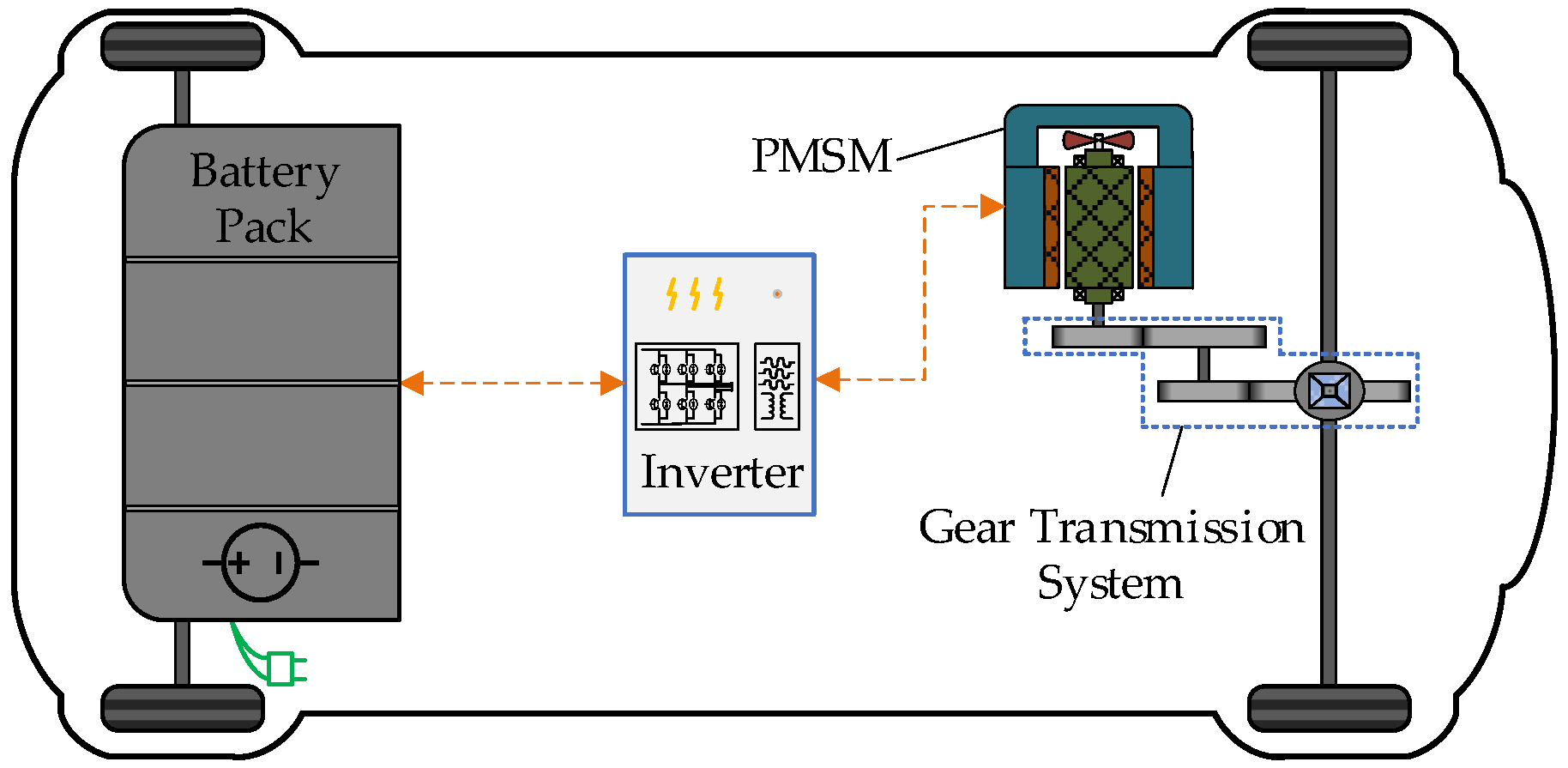
Figure 1. Schematic of the structure of an electric vehicle drive system.
Machines 10 00739 g001
Figure 2. Schematic of the 48-slot, 8-pole PMSM prototype (1/8 of the model).
Machines 10 00739 g002
Figure 3. Inverter A-phase bridge arm circuit path and output voltage waveform diagram: (a) A-phase bridge arm current path diagram; (b) switch signal and output voltage waveform of A-phase bridge arm.
Machines 10 00739 g003
Figure 4. Schematic of an air-gap magnetic field with a nonsinusoidal distribution.
Machines 10 00739 g004
Figure 5. Schematic of the cogging torque generation mechanism.
Machines 10 00739 g005
Figure 6. Comparison results of the cogging torque.
Machines 10 00739 g006
Figure 7. Schematic of the current measurement error.
Machines 10 00739 g007
Figure 8. Schematic of PMSM and its control system model considering non-ideal factors.
Machines 10 00739 g008
Figure 9. Schematic of the principle of SVPWM: (a) schematic of SVPWM sectors; (b) schematic of pulse generation.
Machines 10 00739 g009
Figure 10. Voltage harmonic characteristics and electromagnetic torque characteristics caused by SVPWM: (a) time domain of output line voltage; (b) frequency domain of output line voltage; (c) frequency domain of electromagnetic torque.
Machines 10 00739 g010
Figure 11. Comparison results of current and electromagnetic torque: (a) time domain of A-phase current; (b) frequency domain of A-phase current; (c) time domain of electromagnetic torque; (d) frequency domain of electromagnetic torque.
Machines 10 00739 g011
Figure 12. Frequency domain results of electromagnetic torque under different rotational speeds: (a) waterfall diagram of electromagnetic torque; (b) comparison results of electromagnetic torque.
Machines 10 00739 g012
Figure 13. Frequency domain results of electromagnetic torque under different loads: (a) waterfall diagram of electromagnetic torque; (b) comparison results of electromagnetic torque.
Machines 10 00739 g013
Figure 14. Comparison results of current and electromagnetic torque: (a) time domain of A-phase current; (b) frequency domain of A-phase current; (c) time domain of electromagnetic torque; (d) frequency domain of electromagnetic torque.
Machines 10 00739 g014
Figure 15. Frequency domain results of electromagnetic torque under different speeds: (a) waterfall diagram of electromagnetic torque; (b) comparison results of electromagnetic torque.
Machines 10 00739 g015
Figure 16. Frequency domain results of electromagnetic torque under different loads: (a) waterfall diagram of electromagnetic torque; (b) comparison results of electromagnetic torque.
Machines 10 00739 g016
Figure 17. Comparison results of current and electromagnetic torque: (a) time domain of A-phase current; (b) frequency domain of A-phase current; (c) time domain of electromagnetic torque; (d) frequency domain of electromagnetic torque.
Machines 10 00739 g017
Figure 18. Frequency domain results of electromagnetic torque under different speeds: (a) waterfall diagram of electromagnetic torque; (b) comparison results of electromagnetic torque.
Machines 10 00739 g018
Figure 19. Influence of cogging torque on control performance.
Machines 10 00739 g019
Figure 20. Waterfall diagram of electromagnetic torque.
Machines 10 00739 g020
Figure 21. Comparison results of current and electromagnetic torque: (a) time domain of q-axis current; (b) frequency domain of q-axis current; (c) time domain of electromagnetic torque; (d) frequency domain of electromagnetic torque.
Machines 10 00739 g021
Figure 22. Frequency domain results of electromagnetic torque under different speeds: (a) waterfall diagram of electromagnetic torque; (b) comparison results of electromagnetic torque.
Machines 10 00739 g022
Figure 23. Frequency domain results of electromagnetic torque under different loads: (a) waterfall diagram of electromagnetic torque; (b) comparison results of electromagnetic torque.
Machines 10 00739 g023
Figure 24. Comparison results of current and electromagnetic torque: (a) time domain of A-phase current; (b) frequency domain of A-phase current; (c) time domain of electromagnetic torque; (d) frequency domain of electromagnetic torque.
Machines 10 00739 g024
Figure 25. Flux linkage trajectory comparison.
Machines 10 00739 g025
Figure 26. NVH performance of the motor: (a) color map of electromagnetic torque; (b) time-frequency domain of motor angular acceleration.
Machines 10 00739 g026
Figure 27. Frequency domain results of electromagnetic torque under different speeds: (a) waterfall diagram of electromagnetic torque; (b) comparison results of electromagnetic torque.
Machines 10 00739 g027
Figure 28. Frequency domain results of electromagnetic torque under different loads: (a) waterfall diagram of electromagnetic torque; (b) comparison results of electromagnetic torque.
Machines 10 00739 g028
Figure 29. Comparison results of current harmonic spectrum diagrams: (a) comparison results of current harmonic considering the inverter nonlinearity; (b) comparison results of current harmonic considering the nonsinusoidal distribution of the air-gap magnetic field; (c) comparison results of current harmonic considering the cogging torque; (d) comparison results of current harmonic considering the current measurement error.
Machines 10 00739 g029
Figure 30. Comparison results of electromagnetic torque in the time domain: (a) comparison results of electromagnetic torque considering the inverter nonlinearity; (b) comparison results of electromagnetic torque considering the nonsinusoidal distribution of the air-gap magnetic field; (c) comparison results of electromagnetic torque considering the cogging torque; (d) comparison results of electromagnetic torque considering the current measurement error.
Machines 10 00739 g030
Table 1. Design parameters of the machine prototype.
ParametersValueUnit
Number of poles8
Number of slots48
Stator outer diameter108mm
Rotor outer diameter71mm
Stator inner diameter71.7mm
Rotor inner diameter30mm
Air-gap length0.7mm
Axial length125mm
Length of PM22mm
Thickness of PM4mm
Coercivity of PM92,300A/m
Recovery permeability of PM1.06
Table 2. Main parameters of the PMSM.
ParametersValueUnit
Rated power80kW
Rated torque153Nm
Rated speed4800rpm
Rotary inertia0.04Jm/Kg·m2
Polar logarithm4-
Stator resistance0.01Ω
Flux of PM0.0589Wb
Inductance of axis D1.0146 × 10−4H
Inductance of axis Q2.968 × 10−4H
Table 3. Parameters of the inverter.
ParametersValueUnit
Battery DC voltage600V
Modulation carrier period TPWM100us
Modulation carrier frequency fPWM10kHz
IGBT turn-on time ton1us
IGBT turn-off time toff2us
Dead time td4us
Voltage drop of IGBT switch ut3V
Conduction voltage drop of freewheeling diode ud2V
Delay time of gate pulse rise propagation tPLH0.5us
Delay time of gate pulse drop propagation tPHL0.53us
Table 4. Harmonics of each order of flux linkage and their ratio to the fundamental wave.
OrderMagnitude [Wb]Percent
55.4 × 10−50.092%
77.48 × 10−50.127%
111.113 × 10−40.189%
138.304 × 10−60.014%
174.6 × 10−70.0008%
191.96 × 10−60.003%
Table 5. Parameters of the mathematical equation for the cogging torque.
ParameterValue (N·m)ParameterValue (rad)
T11.89897β10.0000672
T20.379β23.13
T30.2254β33.12
T40.0918β43.236
Table 6. Data comparison before and after considering the non-ideal factors.
ParametersBefore Considering the Non-Ideal FactorsAfter Considering the Non-Ideal Factors
2nd harmonic current amplitude(A)0.361.06
3rd harmonic current amplitude(A)0.081.22
5th harmonic current amplitude(A)0.275.55
7th harmonic current amplitude(A)0.234.28
11th harmonic current amplitude(A)0.191.77
13th harmonic current amplitude(A)0.200.98
17th harmonic current amplitude(A)0.110.2
19th harmonic current amplitude(A)0.120.08
Current distortion rate 3.99%4.59%
Overall fluctuation amplitude
of motor torque(N·m)
2.7810.37
Fluctuation amplitude of
motor shaft speed (rpm)
0.120.37
Publisher’s Note: MDPI stays neutral with regard to jurisdictional claims in published maps and institutional affiliations.