1. Introduction
Saoner Mine No. 1 is a multi-working seam, underground coal mine located in India’s Nagpur District of Maharashtra that uses the board and pillar technique of development. The depth of its coal seams ranged from 50 to 200 m below ground [
1]. A combination of LHD, UDM, and belt conveyors is used to bring coal from subterranean mines to the surface [
2,
3].
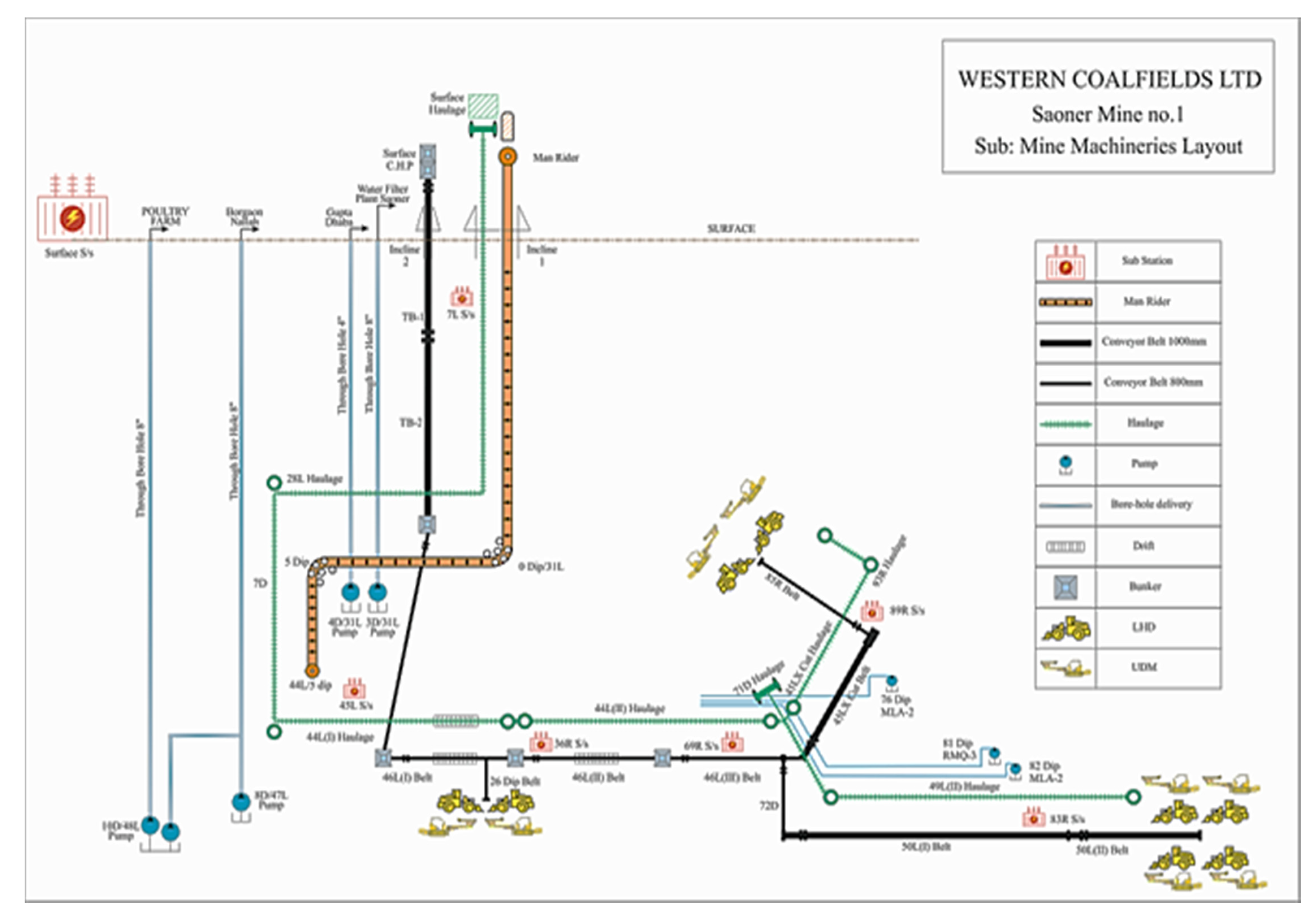
Figure 1 depicts a detailed plan layout demonstrating the deployment of several types of mining machinery. There are two approaches to the subterranean properties of coal. The first is by a vertical shaft-winding engine and cage lift setup, while the second is via drifted inclines accessed by walking in underground mines. Underground coal-mining technologies are used to excavate deep-down coal seam strata in the earth. Mines are open 24 h a day, seven days a week, and progress is made using the board and pillar development approach during every coal-mining operation. The advancement of working faces lengthens the distance that miners must travel to reach their work places. This constant increase in travel distance causes fatigue among miners and reduces productive working time. A man-rider chair lift system is the solution to overcome these situations of the underground mines [
4,
5,
6].
A man-riding system is employed in deeper mines to aid miners in overcoming major transportation obstacles. It helps to reduce travel time without tiring out miners working in subterranean mines while also increasing output. It is a safe, quick, and pleasant method of transporting miners across long distances with uneven horizontal and vertical bends and grades. As production losses are caused by ever-longer underground travel distances, these systems have become increasingly important in modern mining.
The man-rider chair lift system is an electro-hydraulic mechanism with an endless rope. The driving pulley sheave is operated by a hydraulic motor that receives flow from a hydraulic pump and is powered by an electric prime mover. The drive pulley sheave rotates on its axis and revolves the rope due to tension-induced friction between the drive pulley sheave lining and the steel wire rope [
7]. Its rope runs between the hang carrying and depression pulleys on the roof, which are maintained in place by grouted tubes at underground gallery roof, as shown in
Figure 2. The man-riding chairs are securely held on an endless wire rope by positive friction. Roller stations set at regular intervals guide the wire rope itself. The wire rope is driven at the appropriate speed by a drive station located at the system’s head. Specification of MRCL is given in
Table 1.
The embarking and disembarking stations are used to pick up and drop off riders as well as to ensure reliable chair uncoupling and pick-up by the wire rope at the transition area from wire rope to rail, shown in
Figure 3. The return station and tensioning tower weight are erected at the conclusion of the transit section. Curve stations hung in the transport segment by anchoring chains can address horizontal course variations effectively.
The individual rides on the MRCL in the mine use a chair to get from one location to the desired destination and back. The man-riding chairs on an infinite wire rope are held in place by positive friction. The wire is steered by rollers spaced at no more than fifteen-meter intervals. The driving station and return pulleys are securely connected to withstand forces up to the rope’s minimum breaking force. A roof hanging system with a return pulley and proper rope tensioning configuration is used for the return end installation. The return end installation and tensioning column with internal tensioning weight are installed at the downhill end. It is supported by rails and is used to adjust the tensioning distance of the counterweight. This system is also equipped with many safety features such as over-travel and over-speed switch, pull cord rope and switch, pre start alarm, emergency brake, hydraulic brake, telephone and pager phones, etc.
We planned to build a man-rider chair lift system in two stages as part of the mine’s expansion plan. In phase I, MRCL was placed from the surface to the D level, and in phase II, it was expanded up to the G level. When constructing and installing MRCL, the lowest breaking force and applied force on the steel wire are critical criteria. The breaking force must be at least ten times greater than the applied resultant force [
8,
9,
10].
2. Literature Review
The design of mechanical systems can be a very complex task involving the mechanical design itself but also the organization of the shop floor [
11,
12] as well the respective controllers [
13,
14] and communications techniques and possibilities [
15].
In this work, authors devoted attention to the mechanical part of the system as well as safety and reliability issues concerning design and practical implementation in the coal mine.
Ren Zhiqian et al. [
16] used a double Pareto lognormal distribution to examine the fatigue life of steel wire rope under impact stresses. They postulated that the double Pareto lognormal distribution model could accurately reflect the reliability degradation process of wire ropes, providing guidance on wire rope fatigue life computation under diverse impact loads. Shuai Wand et al. [
17] conducted a stress study of steel wire rope under bending with various structural shapes. Based on rope failure and fatigue failure situations, life characterization metrics were provided. They concluded that the structural integrity of the cross-twisted wire rope is superior to that of the co-twisted steel wire rope when bent. Where wear degradation and fatigue stress are dominant, Seale-type co-twisted and cross-twisted steel wire rope is chosen. Juan Felipe Beltran et al. [
18] used experimental and analytical methodologies to investigate the static response of asymmetrical damage to metallic strands of steel wire rope. Damage strands of multilayer strands are regarded as uncoupled biaxial bending and axial stress 1D nonlinear beams. Rope types 1 × 7 and 1 × 19 were employed, with damage levels and strand diameters ranging from 5% to 40% and 3.5 mm to 22.2 mm, respectively. The static response of asymmetrical strand breakage was well-predicted by a nonlinear beam. M. Giglio et al. [
19] investigated the mechanical strength of steel wire rope exposed to axial and bending stresses using stress and strain analysis. The study takes into account the rope used in helicopter rescue hoists that is subjected to swinging off the recovery hook. The analytical results and experimental data were compared in order to forecast the reliability and fatigue life of steel wire rope. Failure analysis of steel wire rope used in overhead cranes was performed by L. Guerra-Fuentes et al. [
20]. They examined wire damage using a visual examination, stereoscopic analysis, scanning electron microscopy, and a micro hardness test to correlate operating conditions with suspected failure causes. Localized plastic distortion occurred in steel wire rope, which was followed by wire wear, stress concentrations, and, eventually, fatigue failure. Using a new technique to failure analysis and prediction, Achraf Wahid et al. [
21] evaluated three damage models for steel wire rope. The first model relies on the modified unified theory, and the second and third models use residual energy models for static damage. The area under the tensile curve for each test is calculated for this one using trapezoidal numerical integration. Based on the obtained results, we can characterize the mechanical behavior of the rope and predict its damage course. Predictive maintenance and cable maintenance were aided by these stages of deterioration. SonglingXue et al. [
22] investigated the slip effects between rope wires when bending and fatigue forces are applied to them using the concept of share-splitting slip. The input parameters were acquired from steel wire rope research. The suspension wire was fatigue tested under tension and bending fatigue using a self-developed testing apparatus. Individual steel wires from the rope were studied under an electron microscope.
3. Research Methodology
It is critical to address risk assessment and safety during the design, installation, and extension stages of MRCL in accordance with the DGMS recommendations as per CMR Regulation 93(6). To relieve the strain pressures produced by travelling long and unequal distances up to the working faces in underground mines, an MRCL was devised to be installed in the mine, with the processes outlined below in
Figure 4.
4. Research Methodology
4.1. Load Calculation for Man Rider
The MRCL was installed at the mines according to the IS 17242-2019 [
23]. The drive head of MRCL is grouted at the pit top of the incline, and its tail end is grouted in the below-ground mine at the desired place up to the length of the installation. The distance between two tubes and two riders is 15 m.
Gradient = Ratio of one meter drop in RL to horizontal distance covered (1:X)
4.2. Calculation of Slope Forces
F1 and F2 are the forces resulting from the weight of persons (assumed average weight 80 kgf/pers);
F3 and F4 are the resulting forces from the weight of chairs (13 kgf/chair);
F1 and F3 are the forces acting in the direction from the drive unit to the return unit.
F
2 and F
4 are the forces acting in the direction from the return to the drive unit, as shown in
Figure 5.
Slope forces acting on the wire rope of MRCL due to the weight of riders and chairs are calculated by the Equations (2)–(5).
4.3. Calculation of Man-Riding Capacity (Mc)
Travelling speed: S (m/s);
Distance between two chairs: Lc = 15 m;
4.4. Calculation of Required Rope Pulling Force (FR)
Summation of the angles of all the horizontal curves of MRCL: αH;
Summation of the angles of all the vertical curves of MRCL: αV;
Rolling resistance of each pulley station in straight section of the installation: RPS;
Rolling resistance due to a rope deviation of 3° (curves, synclines, anticlines): Rθ
Resulting rolling resistance of pulley on either side:
Required pulling force (F
P):
4.5. Calculation for the Required Output of Drive Unit
The drive unit of MRCL is comprised of an electrical motor, hydraulic power pack, hydraulic motor, and drive pulley combined to drive the steel wire rope, as shown in
Figure 6.
Required output of the drive unit (P
O):
Efficiency of the drive unit η;
Required input of the drive unit (electric motor) (P
i):
Required capacity of induction motor = Pi × 1.1 (considered factor 1.1);
Select the nearest and effective capacity of the motor to the calculated value.
4.6. Calculation of Required output of the Rope Safety Factor
Rope safety factor (S.FR) = Ultimate strength/Working stress (FB/FH) must be higher than 10.
Overall maximum inclination (Average) α
m:
Effective length of installation for total vertical deflection of α
m:
Maximum number of riders for the installation:
Horizontal component of force acting on the wire rope:
Vertical component of forces acting on suspension tubes at full capacity of the chair lift system:
4.7. Calculation of Maximum Permissible Load-Bearing Capacity of Holding Bolt/Roof Bolt of Suspension Tubes
Number of suspension tubes for the total length of chairlift system:
Self-weight of suspension tube with carrying and depression pulley (W
ST):
Force acting on each suspension tube due to its own weight:
Force on each suspension tube at maximum capacity of chairlift system:
Force on each suspension tube with two passing at the same time:
Since FSP > FST, we will be considering this force for calculating the load-bearing capacity of roof bolts.
Load test of each roof bolt done with minimum 5000 N;
Two roof bolts are used to fix each suspension tube, and the suspension tube arrangement is shown in
Figure 7.
4.8. Factor of Safety for Each Suspension Tube
4.9. Calculation of Factor of Safety of Tensioning Rope
Figure 8 shows the rope tensioning arrangement along with counter weight.
Weight of counter weight WC = 1500 kgf;
Force on tensioning rope due to counter weight:
Forces acting on tensioning rope:
Minimum breaking force of the tensioning rope BF:
BF = 167,000 N for 16 mm steel wire rope;
BF = 191,000 N for 18 mm steel wire rope.
Factor of safety of tensioning rope:
5. Engineering Calculation for the Design and Installation MRCL at Actual Mining Conditions
Figure 9 shows a side and top perspective of the layout of the MRCL installation and extension phases at underground mines. The technical parameters of Phase I Man-rider installation are mentioned in
Table 2, while,
Table 3 implies the parameters of Phase II Man-rider Extension. All parameters of the mine were considered for the load calculation in both phases and combined parameters of both the phases are mentioned in the
Table 4 [
24].
5.1. Phase-I
The MRCL was installed in two phases; the drive head was installed at pit top with an initial length of 1396 m, and all the technical parameters of this installation are mentioned in
Table 2.
5.2. Phase II Engineering Calculation for the Extension MRCL at Actual Mining Conditions
Further, the MRCL was extended up to the total length of 2819 m in phase II;
Table 3 states all the parameters of phase II.
5.3. Calculation of Power Requirement and Factor of Safety for Man-Riding Lift Chair System in Both Phase I and Phase II
Comparison of phase I and phase II, including all engineering calculation parameters, is given in
Table 5.
The rope should be galvanized and have a long life under typical conditions. The rope’s speed should be changeable between 0 and 3 m/s. The breaking load of the rope should be at least ten times greater than the maximum static load. The time length was set at one year, and it must be assured that this rope life is not exceeded. The rope must adhere to the Indian Standard for aerial ropeways as well as the applicable clause of the Coal Mines Regulations, 2017 [
25].
Table 6 contains the technical specifications for steel wire rope.
If the rope diameter falls below 10% of its original value, and there are more than 17 broken wires in a 1.5 m length or more than 8 broken wires in a 0.24 m length, the rope must be replaced [
26].
6. Analytical Approaches
In the deterministic approach of design considered the strength of the material and the stress applied on it, under this assumption, FOS will be:
However, the reality of the situation is portrayed in the probabilistic method, where stress and strength both vary during operation. The stress fluctuates according to loading cycles, whereas the strength varies due to material deterioration associated with aging, fatigue, corrosion, temperature, and so on. Given that the steel wire rope’s strength and the force applied in phases I and II are normally distributed, the interaction between load and strength in
Figure 10 shows that the greater the safety margin, the safer the system and vice versa. The selection and customization of the range of safety margins is dependent on the system’s applicability and standard norms. High safety factor at a high design margin results in low failure rate [
27,
28,
29,
30].
As far as the safety of the steel wire rope is concerned, the difference between strength and load will be ten times the load, i.e., FOS is 10.
Steel wire rope should be replaced when the strength is less than ten times the load, or S − L < 10 L.
When ten times the load increases the figure of strength:
if S and L are independent variables.
Probability of failure (Pf):
Probability of safety or reliability:
In
Figure 11, the green area represents the MRCL operation’s reliable and safe zone, where the F.O.S. is greater than 10.
7. Computational Approach
The Creo 8.0 version was used to create a model of a 16 mm
2, seven-strand, right-hand-lay steel wire rope for analysis in Ansys R16. 2 software.
Figure 12 depicts a rope model that was produced for use in the program.
Figure 13 and
Figure 14 depict the equivalent stress and normal stress that resulted from applying the mathematically predicted required pulling force in phase I.
Figure 15 and
Figure 16 depict the equivalent stress and normal stress that resulted from applying the mathematically predicted required pulling force in phase II.
Table 7 has illustrated the overall summary of computational approach.
8. Results and Discussion
In this research, mathematical calculations were performed to account for the undulation of underground mines during the design, installation, and extension stages of the MRCL. The minimal breaking force of steel wire rope and the consequent applied force are critical components of design, installation, and extension [
31,
32,
33]. According to the OEM test certificate, the minimum breaking force of 16 sq. mm steel wire rope is 167 KN. The resulting slope forces in phases I and II are 13.226 KN and 15.407 KN, respectively, and the factor of safety is above the recommended limits, i.e., FOS = 10, in both situations and the results are comparable with the existing studies [
34,
35,
36]. It was demonstrated using an analytical approach that the likelihood of failure is about equal to zero, and the probability of safety is approximately equal to one at the reliability index (β) ≥ 3. The steel wire rope’s recommended safety factor is 10; therefore, the MRCL must run at 10 times and above the maximum practically applied resulting slope forces on it [
37,
38]. For the reliability index value of β = 8.95, shown in
Figure 10, the evaluated FOS is 10, beyond which the MRCL must operate. The outcome of a steel wire rope simulation model in Ansys R 16.2 software indicates a very minor difference in equivalent stresses, 15.27 MPa and 18.75 MPa in phase I and phase II, respectively, when the appropriate pulling forces of both phases are applied to it and the findings are superior than existing studies [
38,
39].
9. Conclusions
The MRCL system is a man-riding arrangement designed to move workers in and out of underground mines. It is an endless machine that uses two pulleys, drive and return, to rotate steel wire rope. Curve, carrying, and depression pulleys are used to guide and support the rope of the MRCL installation all the way along its length. As a result of the rope rotating over them, these pulleys are constantly in motion when the MRCL is operating. Following extensive research, it has been determined that the design of a 110 KW electrohydraulic power pack, installation of 1396 m, and extension of the MRCL to a total length of 2819 m is viable in Saoner underground mine no. 1. The steel wire rope must be operated at or above FOS 10 to comply with safety regulations. The minimum breaking strength of a 16 sq mm steel wire rope is 167 KN, and the rope can only be operated with slope forces as high as 16.7 KN. The steel wire rope must be replaced after one year of continuous usage consisting of a minimum of 12 h a day, i.e., 12 × 365 = 4380 h, or every 10% reduction in the original cross-sectional area, whichever comes first. The strength of the steel wire rope decreases as its cross-sectional area decreases, and the impact of the practically resulting slope forces increases as the rope length and angles increase. Both occurrences reduce the factor of safety below ten, which violates the safety norms established by DGMS for the use of steel wire rope in the MRCL. Risk assessment while using the MRCL is negligible, and it is safe for operation for miners while going in and out and to and from the mines.
The novel aspect of this research is that the load was computed mathematically for each and every load-bearing portion of the MRCL and was then validated experimentally and analytically. For both stages, a simulation model of steel wire was examined under the established stresses under loading conditions. This study can aid in the resolution of real-world issues involving the consideration of safety factors for design requirements that include stress and strength characteristics. The study could be useful for any system that deals with changing loads. Studies show that the maximum load applied is below the required factor of safety or the safety standards of the design criteria.
Author Contributions
The authors’ contributions for this paper were multiple and are presented as follows: Conceptualization, S.S., S.P.D., C.L., K.A. and J.M.; methodology, S.S., C.L., S.C. and J.M.; software, M.A.H.S., S.C. and S.A.; validation, S.S., J.M., K.A. and C.L.; formal analysis, S.S., J.M., K.A. and C.L.; investigation, M.A.H.S., S.C., S.S., S.P.D. and S.A.; resources, M.A.H.S., S.C., S.S., S.P.D. and S.A.; data curation, S.S. and C.L; writing—original draft preparation, M.A.H.S., S.C., S.P.D. and S.A.; writing—review and editing, S.S., C.L., K.A. and J.M.; visualization, S.P.D., S.S. and C.L.; supervision, S.S. and J.M.; project administration, S.S.; funding acquisition, K.A. and J.M. All authors have read and agreed to the published version of the manuscript.
Funding
The authors are grateful to FCT—Fundação para a Ciência e Tecnologia (Portugal)—who partially financially supported this work through the RD Units Project Scope: UIDP/04077/2020 and UIDB/04077/2020.
Institutional Review Board Statement
Not applicable.
Informed Consent Statement
Not applicable.
Data Availability Statement
The data presented in this study are available on request from respective authors. The data are not publicly available due to being part of an industrial application study.
Acknowledgments
OEM: M/s Indicon Westfalia Ltd., Kolkata, India, provided and installed the MRCL with the assistance of WCL authorities. The OEM has given relevant information. The authors are especially appreciative of the OEM for their assistance involving installation, technical support, and accessibility of information. The views are of the authors for calculating reliability and relating with the model and practical installation.
Conflicts of Interest
The authors declare no conflict of interest.
Nomenclature
| L = l1 + l2 + l3 + … ln | Length of installation |
| Lc | Distance between two chairs |
| LP | Distance between two pulley tubes |
| Mc | Man-riding capacity |
| D | Diameter of drive unit sheave |
| S | Travelling speed |
| DR | Rope diameter |
| FB | Minimum breaking force for rope |
| WR | Weight of wire rope |
| WR15 | Weight of 15 m wire rope |
| WP | Weight of person acting on rope |
| WC | Weight of chair acting on rope |
| FP.D | Force of person acting on rope while moving downward to the mine |
| FP.U | Force of person acting on rope while moving upward from the mine |
| FC.D | Force of chair acting on rope while moving downward to the mine |
| FC.U | Force of chair acting on rope while moving upward from the mine |
References
- Siddiqui, M.; Pal, S.K.; Dewangan, N.; Chattopadhyaya, S.; Sharma, S.; Nekoonam, S.; Issakhov, A. Sludge Formation Analysis in Hydraulic Oil of Load Haul Dumper 811MK V Machine Running at Elevated Temperatures for Bioenergy Applications. Int. J. Chem. Eng. 2021, 2021, 4331809. [Google Scholar] [CrossRef]
- Siddiqui, M.A.H.; Chattopadhyaya, S.; Sharma, S.; Assad, M.E.H.; Li, C.; Pramanik, A.; Kilinc, H.C. Real-Time Comprehensive Energy Analysis of the LHD 811MK-V Machine with Mathematical Model Validation and Empirical Study of Overheating: An Experimental Approach. Arab. J. Sci. Eng. 2022, 47, 9043–9059. [Google Scholar] [CrossRef]
- Siddiqui, M.A.H.; Akhtar, S.; Chattopadhyaya, S.; Sharma, S.; Assad, M.E.H.; Singh, J.; Aggarwal, V.; Dwivedi, S.P.; Saxena, A. Investigation of geo-mining green roof seismic energy balancing with resin bolting by Universal Drilling Machine: A novel energy-absorbing-based support system. Arab. J. Geosci. 2022, 15, 431. [Google Scholar] [CrossRef]
- Siddiqui, M.A.H.; Agrawal, A.K.; Chattopadhyaya, S. In Situ Non-destructive Testing of Man Riding Chair Lift System. In Proceedings of International Conference in Mechanical and Energy Technology; Springer: Singapore, 2020. [Google Scholar]
- Iphar, M.; Cukurluoz, A.K. Fuzzy risk assessment for mechanized underground coal mines in Turkey. Int. J. Occup. Saf. Ergon. 2020, 2, 256–271. [Google Scholar] [CrossRef]
- Niczyporuk, Z.T. Safety management in coal mines—Risk assessment. Int. J. Occup. Saf. Ergon. 1996, 2, 243–250. [Google Scholar] [CrossRef]
- Feyrer, K. Wire Ropes; Springer: Berlin/Heidelberg, Germany, 2007. [Google Scholar]
- Peterka, P.; Krešák, J.; Kropuch, S.; Fedorko, G.; Molnar, V.; Vojtko, M. Failure analysis of hoisting steel wire rope. Eng. Fail. Anal. 2014, 45, 96–105. [Google Scholar] [CrossRef]
- Singh, R.; Mallick, M.; Verma, M. Studies on failure behaviour of wire rope used in underground coal mines. Eng. Fail. Anal. 2016, 70, 290–304. [Google Scholar] [CrossRef]
- Chang, X.-D.; Huang, H.-B.; Peng, Y.-X.; Li, S.-X. Friction, wear and residual strength properties of steel wire rope with different corrosion types. Wear 2020, 458–459, 203425. [Google Scholar] [CrossRef]
- Sousa, R.A.; Varela, M.L.R.; Alves, C.; Machado, J. Job shop schedules analysis in the context of industry 4.0. In Proceedings of the 2017 International Conference on Engineering, Technology and Innovation: Engineering, Technology and Innovation Management Beyond 2020: New Challenges, New Approaches, ICE/ITMC 2017-Proceedings, Madeira, Portugal, 27–29 June 2017. [Google Scholar] [CrossRef]
- Arrais-Castro, A.; Varela, M.L.; Putnik, G.; Ribeiro, R.; Machado, J.; Ferreira, L. Collaborative framework for virtual organisation synthesis based on a dynamic multi-criteria decision model. Int. J. Comput. Integr. Manuf. 2018, 31, 857–868. [Google Scholar] [CrossRef]
- Canadas, N.; Machado, J.; Soares, F.; Barros, C.; Varela, L. Simulation of cyber physical systems behaviour using timed plant models. Mechatronics 2018, 54, 175–185. [Google Scholar] [CrossRef]
- Campos, J.C.; Machado, J.; Seabra, E. Property patterns for the formal verification of automated production systems. In Proceedings of the IFAC Proceedings Volumes (IFAC-PapersOnline), 17(1 PART 1), 17th World Congress, International Federation of Automatic Control, IFAC, Seoul, Korea, 6–11 July 2008. [Google Scholar] [CrossRef]
- Kunz, G.; Machado, J.; Perondi, E.; Vyatkin, V. A Formal Methodology for Accomplishing IEC 61850 Real-Time Communication Requirements. IEEE Trans. Ind. Electron. 2017, 64, 6582–6590. [Google Scholar] [CrossRef]
- Zhiqian, R.; Xun, C. Research on fatigue life of steel wire ropes under impact loads based on double Pareto lognormal distribution. Adv. Mech. Eng. 2017, 9, 1–7. [Google Scholar] [CrossRef]
- Wang, S.; Liu, F.; Du, Y.; Meng, G. Stress analysis and life improvement of steel wire rope under bending process. Mech. Ad-Vanced Mater. Struct. 2020, 28, 1–10. [Google Scholar]
- Beltrán, J.F.; Nuñez, E.; Nuñez, F.; Silva, I.; Bravo, T.; Moffat, R. Static response of asymmetrically damaged metallic strands: Experimental and numerical ap-proach. Constr. Build. Mater. 2018, 192, 538–554. [Google Scholar] [CrossRef]
- Giglio, M.; Manes, A. Life prediction of a wire rope subjected to axial and bending loads. Eng. Fail. Anal. 2004, 12, 549–568. [Google Scholar] [CrossRef]
- Guerra-Fuentes, L.; Torres-López, M.; Hernandez-Rodriguez, M.; Garcia-Sanchez, E. Failure analysis of steel wire rope used in overhead crane system. Eng. Fail. Anal. 2020, 118, 104893. [Google Scholar] [CrossRef]
- Wahid, A.; Mouhib, N.; Ouardi, A.; Sabah, F.; Chakir, H.; Elghorba, M. Experimental prediction of wire rope damage by energy method. Eng. Struct. 2019, 201, 109794. [Google Scholar] [CrossRef]
- Xue, S.; Shen, R.; Shao, M.; Chen, W.; Miao, R. Fatigue failure analysis of steel wire rope sling based on share-splitting slip theory. Eng. Fail. Anal. 2019, 105, 1189–1200. [Google Scholar] [CrossRef]
- Webber-Youngman, R.C.W.; van Heerden, G.M.J. Engineering principles for the design of a personnel transporta-tion system. J. S. Afr. Inst. Min. Metall. 2016, 116, 441–454. [Google Scholar] [CrossRef] [Green Version]
- Van Heerden, G.M.J. Engineering Principles for the Design of a New/Existing Mine’s Personnel Transportation System (Case Study BafokengRasimone Platinum Mine). Ph.D. Thesis, University of Pretoria, Pretoria, South Africa, 2014. [Google Scholar]
- Coal Mines Regulation 2017.pdf-160 The Gazette Of India: Extraordinary [Part Ii-Sec. 3(I)] Ministry of Labour and Employment Notification New Delhi | Course Hero. (n.d.). Available online: https://www.coursehero.com/file/52793434/Coal-Mines-Regulation-2017pdf/ (accessed on 19 July 2022).
- Ridge, I.; Chaplin, C.; Zheng, J. Effect of degradation and impaired quality on wire rope bending over sheave fatigue endurance. Eng. Fail. Anal. 2001, 8, 173–187. [Google Scholar] [CrossRef]
- Meksem, A.; El Ghorba, M.; Benali, A.; El Barkany, A. Optimization by the Reliability of the Damage by Tiredness of a Wire Rope of Lifting. Appl. Mech. Mater. 2011, 61, 15–24. [Google Scholar] [CrossRef]
- Salleh, S.; Abdullah, M.; Abdulhamid, M.; Tamin, M. Methodology for reliability assessment of steel wire ropes under fretting fatigue conditions. J. Mech. Eng. Sci. 2017, 14, 2488–2502. [Google Scholar] [CrossRef]
- Wessels, W. Practical Reliability Engineering and Analysis for System Design and Life-Cycle Sustainment; CRC Press: Boca Raton, FL, USA, 2010. [Google Scholar] [CrossRef]
- Todinov, M. Reliability and Risk Models: Setting Reliability Requirements; John Wiley & Sons: Hoboken, NJ, USA, 2015. [Google Scholar]
- Lv, Z.; Guo, J.; Lv, H. Safety Poka Yoke in Zero-Defect Manufacturing Based on Digital Twins. IEEE Trans. Ind. Inform. 2022. [Google Scholar] [CrossRef]
- Zhang, C.; Mousavi, A.A.; Masri, S.F.; Gholipour, G.; Yan, K.; Li, X. Vibration feature extraction using signal processing techniques for structural health monitoring: A review. Mech. Syst. Signal Process. 2022, 177, 109175. [Google Scholar] [CrossRef]
- Huang, H.; Huang, M.; Zhang, W.; Yang, S. Experimental study of predamaged columns strengthened by HPFL and BSP under combined load cases. Struct. Infrastruct. Eng. 2020, 17, 1210–1227. [Google Scholar] [CrossRef]
- Xu, J.; Park, S.H.; Zhang, X.; Hu, J. The Improvement of Road Driving Safety Guided by Visual Inattentional Blindness. IEEE Trans. Intell. Transp. Syst. 2022, 23, 4972–4981. [Google Scholar] [CrossRef]
- Guo, Y.; Yang, Y.; Kong, Z.; He, J.; Wu, H. Development of Similar Materials for Liquid-Solid Coupling and Its Application in Water Outburst and Mud Outburst Model Test of Deep Tunnel. Geofluids 2022, 2022, 8784398. [Google Scholar] [CrossRef]
- Zhu, Z.; Wu, Y.; Liang, Z. Mining-Induced Stress and Ground Pressure Behavior Characteristics in Mining a Thick Coal Seam With Hard Roofs. Front. Earth Sci. 2022, 10, 843191. [Google Scholar] [CrossRef]
- Zheng, W.; Zhou, Y.; Liu, S.; Tian, J.; Yang, B.; Yin, L. A Deep Fusion Matching Network Semantic Reasoning Model. Appl. Sci. 2022, 12, 3416. [Google Scholar] [CrossRef]
- Wang, J.; Tian, J.; Zhang, X.; Yang, B.; Liu, S.; Yin, L.; Zheng, W. Control of Time Delay Force Feedback Teleoperation System with Finite Time Convergence. Front. Neurorobot. 2022, 16, 877069. [Google Scholar] [CrossRef]
- Lu, S.; Ban, Y.; Zhang, X.; Yang, B.; Liu, S.; Yin, L.; Zheng, W. Adaptive control of time delay teleoperation system with uncertain dynamics. Front. Neurorobot. 2022, 16, 928863. [Google Scholar] [CrossRef] [PubMed]
Figure 1.
Detailed layout of underground coal mine of Saoner Mine No.1, Nagpur Area, Western Coal Fields Limited, Coal India Limited, India.
Figure 1.
Detailed layout of underground coal mine of Saoner Mine No.1, Nagpur Area, Western Coal Fields Limited, Coal India Limited, India.
Figure 2.
Basic arrangement of MRCL.
Figure 2.
Basic arrangement of MRCL.
Figure 3.
Embarking and Disembarking Station.
Figure 3.
Embarking and Disembarking Station.
Figure 4.
Research Methodology.
Figure 4.
Research Methodology.
Figure 5.
Forces acting on wire rope.
Figure 5.
Forces acting on wire rope.
Figure 6.
MRCL Drive Unit.
Figure 6.
MRCL Drive Unit.
Figure 7.
Suspension tube grouted with two number of roof bolt.
Figure 7.
Suspension tube grouted with two number of roof bolt.
Figure 8.
Rope Tensioning Unit.
Figure 8.
Rope Tensioning Unit.
Figure 9.
Top View and Side View of MRCL.
Figure 9.
Top View and Side View of MRCL.
Figure 10.
Load and Strength relationship.
Figure 10.
Load and Strength relationship.
Figure 11.
Reliability Index of MRCL.
Figure 11.
Reliability Index of MRCL.
Figure 12.
Simulation view of the steel wire rope.
Figure 12.
Simulation view of the steel wire rope.
Figure 13.
Phase I Equivalent Stress distributions on steel wire rope.
Figure 13.
Phase I Equivalent Stress distributions on steel wire rope.
Figure 14.
Phase I Normal Stress distributions on steel wire rope.
Figure 14.
Phase I Normal Stress distributions on steel wire rope.
Figure 15.
Phase II Equivalent Stress distributions on steel wire rope.
Figure 15.
Phase II Equivalent Stress distributions on steel wire rope.
Figure 16.
Phase II Normal Stress distributions on steel wire rope.
Figure 16.
Phase II Normal Stress distributions on steel wire rope.
Table 1.
Specification of MRCL.
Table 1.
Specification of MRCL.
| Type and Make | Drive Power | Rope Speed | Maximum
Horizontal Curves | Maximum
Gradients | Pulling Force | IS Specification |
|---|
| Electro-hydraulic-operated, roof hanged, endless type, and SCHARF make | 3 ph, 50 Hz,110 KW/550 Volt, IP-55, IS 4691 | 0–3 m/s | 90° | 1:4.5 or 45 degrees | Less than ten times the minimum breaking strength of rope | IS 17242 2019 |
Table 2.
Phase I Man-rider Installation.
Table 2.
Phase I Man-rider Installation.
| Phase-I |
|---|
| Sections of the Chairlift in Sequence from the Drive Unit to the Return Unit | Inclination | Sine of Inclination | Slope Force |
|---|
| | Horizontal Distance | Curve Station | Gradient
(1 m RL: Horizontal Distance) | ϕ | Sinϕ | Person | | Chair |
|---|
| Level | Level | (m) | | 1:X | | | F1
(N) | F2
(N) | F3
(N) | F4
(N) |
|---|
| Level A to Level B =
| 930 | | 1:5 | 11.31 | 0.196 | 9527 | | 1548 | |
| Level B to Level C =
| 140 | 90° to
| 1:50 | 1.15 | 0.020 | 146 | | 24 | |
| Level D to Level D =
| 326 | 90° to
| 1:10 | 5.72 | 0.100 | 1703 | | 277 | |
| Total | 1396 | 180o | | 18.16 | | 11,377 | | 1849 | |
Table 3.
Phase II Man-rider Extension.
Table 3.
Phase II Man-rider Extension.
| PHASE-II |
|---|
| Sections Of The Chairlift In Sequence From The Drive Unit To The Return Unit | Inclination | Sine of Inclination | Slope force |
|---|
| | Horizontal Distance | Curve Station | Gradient
(1 m RL: Horizontal Distance) | ϕ | Sinϕ | Person | | Chair |
|---|
| Level | Level | (m) | | 1:X | | | F1 (N) | F2 (N) | F3 (N) | F4 (N) |
|---|
| Level D to Level E =
| 40 | | 1:10 | 5.71 | 0.10 | 209 | | 34 | |
| Level E to Level F =
| 53 | 12° to
| 1:10 | 5.71 | 0.10 | 277 | | 45 | |
| Level F to Level G =
| 1330 | 64.5° to
| 1:50 | 1.14 | 0.02 | 1390 | | 226 | |
| Total | 1423 | 76.5° | | 12.56 | | 1876 | | 305 | |
Table 4.
Combined Framework of Phase I and Phase II.
Table 4.
Combined Framework of Phase I and Phase II.
| Phase I | Horizontal Distance (m) | Curve Station (°) | Inclination Ø (°) | Slope Force Person | Slope Force Chair |
|---|
| + |
|---|
| Phase II | F1 (N) | F2(N) | F3(N) | F4(N) |
|---|
| Total | 2819 | 256.5 | 30.733 | 13,254 | 2154 |
Table 5.
Power and Factor of Safety Calculation.
Table 5.
Power and Factor of Safety Calculation.
| Calculation of Power and Rope Safety Factor | | Phase I | Phase II | Unit |
|---|
| Diameter of drive unit sheave | | 1500 | 1500 | mm |
| Rope diameter | | 16 | 16 | mm |
| Minimum breaking force for 16 sq. mm rope | | 167 | 167 | KN |
| Weight of wire rope | | 91.5 | 91.5 | kg/100 m |
| Weight of 15 m wire rope | | 13.73 | 13.73 | kg |
| Travelling speed | S | 1.5 | 1.5 | m/s |
| Distance between two chairs | | 15 | 15 | m |
| Man-riding capacity | | 360 | 360 | Pers/h |
| Total length of installation | L | 1396 | 2819 | m |
| Over all maximum inclination over the span | α max | 11.3 | 11.3 | Deg |
| Distance between the pulley station | | 15 | 15 | m |
| Summary of the angles of all the horizontal curves | | 180 | 256 | Deg |
| Summary of the angles of all the vertical curves | | 36 | 61 | Deg |
| Rolling resistance of each pulley station | | 20 | 20 | N |
| Rolling resistance due to a rope deviation of 3 degrees (curves, synclines, anticlines) | | 39 | 39 | N |
| Resulting slope force | | 13,226 | 15,407 | N |
| Resulting in the rolling resistance of pulleys on either side | | 4752 | 8043 | N |
| Efficiency of the drive unit | ɳ | 0.9 | 0.9 | |
| Required pulling force | | 23 | 32 | KN |
| Required output of the drive unit | | 65 | 90 | KW |
| Required input of the drive unit (e-motor) | | 72 | 100 | KW |
| Required capacity of electric motor | | 80 | 110 | KW |
| Capacity of L motor to be selected | M | 110 | 110 | KW |
| Rope safety factor | | 12.6 | 10.8 | |
| Effective length of installation for total vertical deflection of 60 (approx.) | LE | 1454 | 2936 | M |
| Maximum number of riders for the installation | | 186 | 376 | Nos. |
| Horizontal component of force acting on wire rope | FHC | −1165 | −2630 | N |
| Vertical component of force acting on suspension tubes at full capacity of the chair lift system | FVS | 195,795 | 395,743 | N |
| Number of suspension tubes for the total of chairlift system | T | 100 | 202 | N |
| Self-weight of suspension tube with carrying and depression pulley | WST | 100 | 100 | kg |
| Force acting on each suspension tube due to its own weight | FSS | 981 | 981 | N |
| Force on each suspension tube at maximum capacity of chairlift system | FST | 2939 | 2940 | N |
| Force acting on each suspension tube with two persons passing at the same time | FSP | 3212 | 3212 | N |
| Maximum permissible load bearing of each roof blot of two numbers fixed in suspension tube | ST | 3.11 | 3.11 | N |
| Force on tensioning rope due to counter weight | FCW | 14,715 | 14,715 | N |
| Force acting on tensioning rope | FWR | 13,550 | 12,084 | N |
| Minimum breaking force of the tensioning rope | | 167,000 | 167,000 | N |
| Factor of safety of tensioning rope | | 12.32 | 13.81 | |
Table 6.
Steel Wire Rope Specifications.
Table 6.
Steel Wire Rope Specifications.
| Steel Wire Rope | Nominal Diameter | Length | Construction | Strand Construction | Tensile Grade | Type of Core | Lay Direction | Minimum Breaking Force |
|---|
| IS-1855/2003 (Marked) | 16 mm
IS 6594 | Phase I—3 km
Phase II—6 km | 6 × 7, preformed, galvanized | 6-1 | 1960 N/mm2 | SISAL | RHL
IS 6594 | 16 mm2 = 167 KN
IS 1608 |
Table 7.
Summary of computational approach.
Table 7.
Summary of computational approach.
| Sr. No. | Phase | Normal Stress (Mpa) | Equivalent Stress (MPa) |
|---|
| 1 | Phase I (22.7 KN) | 1.25 | 15.27 |
| 2 | Phase II (31.4 KN) | 2.62 | 18.75 |
| Publisher’s Note: MDPI stays neutral with regard to jurisdictional claims in published maps and institutional affiliations. |
© 2022 by the authors. Licensee MDPI, Basel, Switzerland. This article is an open access article distributed under the terms and conditions of the Creative Commons Attribution (CC BY) license (https://creativecommons.org/licenses/by/4.0/).


 ,
, 


