Abstract
In this paper, the AC copper losses in classical random windings are investigated and mitigated using several techniques across a range of permanent magnet synchronous motor designs. At high operating frequencies, AC copper losses can represent a substantial share of the total loss in electrical machines, thus, reducing the machine’s overall performance, and increasing the thermal loading. Recently, different approaches for modelling AC copper losses have been proposed. This paper utilises simulation software to quantify the expected AC losses in six different propulsion motor designs. The motor designs are then modified to reduce the AC winding losses through the implementation of five different methods. Using two-dimensional finite element analysis, the magnetisation direction, magnet to airgap ratio, copper stranding, magnetic wedges and the motor slot openings are modified to reduce AC losses. The paper considers distributed, fractional, slot and concentrated windings, and the results show promising reductions across these different winding configurations.
1. Introduction
The growing demand for aircraft electrification emphasizes the need for more efficient, reliable, and higher torque density motors. In turn, this has helped to drive the development of high-performance permanent magnet synchronous motors (PMSM) [1,2,3,4]. In order to achieve these challenging requirements, the motor losses need to be minimised. The winding losses usually account for the highest proportion of the losses, especially in the low-to-medium operating frequency range.
At high operating and switching frequencies, the winding AC losses become more prevalent in electrical motors [5,6,7]. This is especially true in hairpin winding machines [8,9]. However, the focus of this paper contribution is on classical random windings with round wires. Although hairpin winding achieves a higher fill factor than conventional random windings with round wires, the number of possible layout configuration is limited. In [10], the AC losses were investigated for six outer rotor motors, employing concentrated windings by machining a block of copper to fill the maximum slot area.
The estimation of the AC winding losses can be a very challenging task, so different approaches have been proposed and investigated to improve accuracy and reduce the computation times [6,11,12,13,14,15,16,17,18,19,20,21]. However, the advantages of reducing these losses at earlier stages of the electrical machine design are of critical importance for a comprehensive machine design practice [22,23,24,25].
The AC losses are caused by the time-varying magnetic fields experienced by electrical machine windings. They are usually overlooked in the fundamental Ohmic loss model, which assumes that current is spread uniformly in the conductor. The magnetic fields generate a non-uniform current distribution, and the non-linear variation in Ohmic loss with current density results in a net increase in total loss.
The time-varying magnetic fields that influence the current distribution are caused by the following three sources: alternating current in the conductor, alternating current in neighbouring conductors, and rotating permanent magnets [15]. The ‘skin effect’ is caused by the conductor’s own, self-induced field, which causes greater current to flow at the outside edges of the conductor cross-section than at the centre. The ‘proximity effect’ refers to the effect of external fields (from nearby conductors or magnets) [26]. Flux leakage into the slot also contributes to the total AC losses. In some cases, the losses generated from flux leakage can reach up to 21% of the total AC losses [10].
These effects are minimal at lower frequencies, but when the frequency rises into the hundreds of Hertz range, depending on the tooth and slot geometry, airgap thickness, magnet arrangement, wire size and shape, and coil positioning, the AC loss may become substantial [15,16]. Indeed, AC losses in aluminium and copper hairpin windings have been compared in [27], where it was recommended that, for fundamental frequencies higher than 1 kHz, aluminium windings are recommended.
A popular AC loss mitigation strategy, especially for random windings, is to lower the height of the winding in the slot to lessen the field impinging on the conductors, which improves high-frequency AC performance but compromises low-frequency DC performance, due to poor slot area utilisation [16,28,29]. A second strategy is to set the profile/arrangement of the conductors in the slot to minimise interaction with the armature reaction field while maximising the slot area usage [16,28,29,30]. This can be achieved by winding the turns onto forming bobbins, thus, conforming into a specific shape that minimises the AC losses, also known as the bundle effect. Recently, the application of additive manufacturing technologies has been demonstrated, which provide exceptional geometric freedom in conductor shape and layout [23,31].
This paper is dedicated to reducing the AC winding losses of six of the proposed aircraft propulsion motor designs, by implementing five approaches. As reported in [32], investigations of different slot/pole combinations for propulsion motors are proposed. The motors under consideration are categorised into three winding configurations, as follows: the distributed windings are represented by the S48-P16 and S60-P20, the fractional slot windings by S60-P16 and S72-P22, and, finally, concentrated windings are the S24-P20 and S36-P30, where ‘S’ refers to the number of slots, and ‘P’ refers to the number of poles. A diagram showing a quarter of each motor is shown in Figure 1. Five different methods are proposed to mitigate the AC losses, as follows:
- (1)
- By adjusting the airgap flux density through the permanent magnet (PM) magnetisation direction;
- (2)
- Adjusting the PM-to-airgap ratio;
- (3)
- By pushing the winding away from the slot opening;
- (4)
- The use of multi-strands;
- (5)
- By modifying the slope opening shape and the addition of a magnetic slot wedge. The combination of several motor designs and winding combinations for loss reduction in this paper provides extensive guidelines for AC loss reduction in random wound windings.
The paper is organised as follows: Section 2 is a preliminary calculation of the AC losses of the six motors, before implementing the proposed AC loss reduction method. In Section 3, the proposed methods, the framework of the proposed techniques, and the results of these analyses are presented. In Section 4, a quantitative and qualitative discussion of the results is given. Finally, conclusions and final remarks are added in Section 5.

Figure 1.
Schematic showing a radial sectioned view through a quadrant of the proposed motors, (a) S24-P20, (b) S36-P30, (c) S48-P16, (d) S60-P16, (e) S60-P20, and (f) S72-P22.
Figure 1.
Schematic showing a radial sectioned view through a quadrant of the proposed motors, (a) S24-P20, (b) S36-P30, (c) S48-P16, (d) S60-P16, (e) S60-P20, and (f) S72-P22.

2. Analysis Framework and Proposed AC Loss Reduction Techniques
This paper compares the performance and behaviour of six motor designs. An initial analysis of the AC winding losses and an outline of the selected motors’ main performance indicators are listed in Table 1. The Motor-CAD V13.0 electromagnetic solver is used to model these motors for this whole study. It should be noted that the Motor-CAD solver considers only the proximity and skin effects. In an ideal system, the AC effects would be zero. For example, if Litz wires are used, it is acceptable to reach 10–20% of the DC losses [12,33,34,35,36,37,38].

Table 1.
Motors were considered for the AC winding losses study.
All the motors investigated have an outer diameter of 463 mm and a stack length of 151 mm. More detailed design parameters can be found in [32,39]. A motor with an output power in the range of 500 kW, operating at frequencies up to 500 Hz and a required efficiency of 98% would result in total losses of 10 kW, the majority of which are expected from the windings and PMs. The losses also drive the cooling requirements, so by targeting a reduction in AC loss, cooling systems can be reduced in size, mass, and cost.
Considering the results calculated in Table 1, the lowest ratio of AC to DC loss is 1.5 and 1.6 for the S60-P20 and S6-P16 motors, respectively, hence, it is 7 times higher than using Litz wires. Concentrated windings have very high AC losses, due to the high harmonic content at the airgap.
A fixed value for the phase current is set at 200 amps, while the fill factor for these random wound wires is maximised and has a range between 0.48 and 0.62. The output power has a maximum of 543 kW for the S60-P20 motor, and the average is 520 kW. The wire diameter in Table 1 is considered for a single strand per turn, which will be addressed later in the paper.
Different approaches [22,23,24] can be implemented to reduce these losses, including stranding and moving windings away from the slot opening. Additionally, the airgap flux density can be adjusted to reduce high-frequency harmonics. This can be achieved by varying the PM-to-airgap thickness ratio, changing the slot opening geometry, or using a magnetic slot wedge, amongst other methods [40].
Three winding configurations are considered, as they represent the possible scenarios when designing a PMSM. Hence, for each of these winding configurations two motors are included in the analysis. In this paper, the distributed winding motors are S60-P20 and S48-P16, the fractional slot windings are S60-P16 and S72-P22, and, finally, the concentrated winding designs are the S24-P20 and S36-P30. These motors were designed and optimised for the purpose of propulsion of small regional aircraft. Therefore, the operation and comparison are based on this application at a fixed base speed rather than at a fixed frequency.
The first and second methods proposed to reduce the AC losses focus on the PM and airgap flux density. This is carried out by studying the impact of the different magnetisation orientations of the PM and comparing the performance of the Halbach array, radial magnetisation, and parallel magnetisation. Then, the analysis is carried out by considering a wide range of PM-to-airgap thickness ratios to optimise the airgap flux density.
The third method deals directly with the winding by applying the concepts of stranding the winding turns and pushing the windings away from the slot opening to minimise the proximity and skin effects.
The fourth and fifth methods shift the focus to the slot design, by reshaping the teeth to change the slot from an open to closed design through varying degrees of freedom. Then, a magnetic slot wedge is added as an additional measure to reduce the AC losses.
Therefore, the proposed framework of motor designs and methods are inclusive of a wide range of designs, winding configurations, and design considerations. Hence, it should provide a design guideline for future motor design when winding AC losses are considered.
3. Results
The methodology, results and preliminary conclusions for each of the proposed loss reduction methods are discussed in this section.
3.1. Approach A: PM Magnetisation
Here, PMs arranged in a Halbach array (HBA) are adopted for these motors [39]. In this study, HBAs are used since they provide stronger and more sinusoidal flux. However, as they produce a stronger magnetic field in the airgap and the slot opening, higher AC losses are generated. The AC losses are also highly influenced by the frequency and, therefore, maintaining a lower harmonic content can ensure that losses are kept to a minimum. Sinusoidal magnetic fields have a lower harmonic content, but higher magnetic field densities impose more saturation in the tooth tips.
Thus, a trade-off between more sinusoidal flux and the strength of the field needs to be studied. Compared to radial or parallel magnetisation, the HBA requires a reduced back-iron area, which is advantageous in terms of the overall power density of the motor. If the same area was used for parallel or radial magnetisation, the output power would be significantly reduced. Therefore, for a fairer comparison, the back-iron of the rotor has been modified—specifically, increased—when simulating the parallel and radial magnetisation, as illustrated in Figure 2. If the same narrow rotor back-iron is used in the parallel or radial magnetisation, then it would have restricted the motor performance. Thus, the back-iron was increased to accommodate this change. However, by doing so, the airgap flux density is increased and, thus, the flux density in the slot opening is also higher.
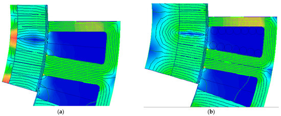
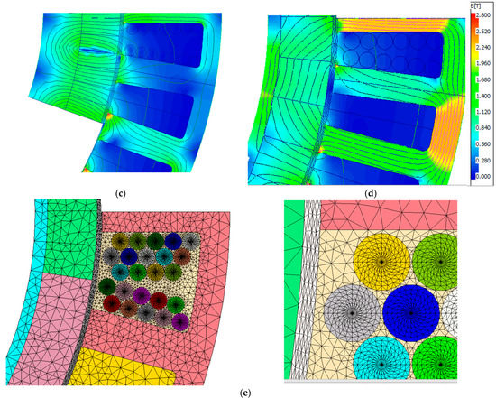
Figure 2.
PM magnetisation results, flux density map with the same legend as in (d), with the S36-P30 as an example—(a) parallel with narrow back-iron, (b) parallel with wide back-iron, (c) radial with wide back-iron, (d) Halbach array, (e) an example of the conductor’s mesh.
A summary of the results is identified in Table 2 and Figure 3. The HBA is superior in terms of overall performance for all the motors, specifically in terms of output power and efficiency, as well as torque ripple. Additionally, the phase voltage THD is lower in HBA designs, as justified earlier, due to the increased sinusoidal magnetic flux. Due to lower values of flux density for the radial and the parallel PM magnetisation, the AC losses are lower in most cases. In general, the reduction in the AC losses is achieved for the S72-P22, S24-P20, and S36-P30 motors. The maximum reduction is 24%, though it comes at the cost of a reduction in output power of 5% to 20%. Despite the possible reduction in AC losses by changing from HBA to radial or parallel magnetisation, the performance of the motors with the HBA is generally better. However, between the radial and the parallel magnetisation, the radial magnetisation has a slightly lower AC loss. However, the overall performance, such as in terms of output power, torque ripple, and phase voltage THD, is better in parallel than radial magnetisation. Finally, the HBA are still generally recommended due to the higher output power, lower torque ripple, and THD. Hence, the general recommendation is to keep the HBA for these motor configurations.
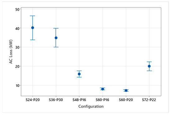
Figure 3.
AC to DC loss ratio for the PM-to-airgap ratio study.
Table 2.
PM magnetisation analysis results for AC losses reduction.
Table 2.
PM magnetisation analysis results for AC losses reduction.
| Combination | S60-P20 | S48-P16 | S60-P16 | S72-P22 | S24-P20 | S36-P30 | |
|---|---|---|---|---|---|---|---|
| Torque (kN/m) | Halbach | 2.60 | 2.50 | 2.53 | 2.58 | 2.26 | 2.42 |
| Radial | 2.21 | 2.33 | 2.32 | 2.32 | 2.01 | 1.90 | |
| Parallel | 2.31 | 2.40 | 2.40 | 2.39 | 2.08 | 1.98 | |
| Torque Ripple (%) | Halbach | 3.1 | 21.8 | 1.7 | 1.4 | 2.1 | 1.4 |
| Radial | 19.2 | 31.8 | 2.1 | 1.4 | 5.4 | 2.7 | |
| Parallel | 19.5 | 31.2 | 1.7 | 1.6 | 5.9 | 2.7 | |
| Pout (kW) | Halbach | 545 | 525 | 529 | 540 | 475 | 510 |
| Radial | 463 | 488 | 487 | 486 | 422 | 399 | |
| Parallel | 485 | 503 | 503 | 502 | 438 | 416 | |
| DC Loss (kW) | Halbach | 4.9 | 4.1 | 5.5 | 4.4 | 2.8 | 3.2 |
| Radial | 4.9 | 4.1 | 5.5 | 4.4 | 2.8 | 3.2 | |
| Parallel | 4.9 | 4.1 | 5.5 | 4.4 | 2.8 | 3.2 | |
| AC losses (kW) | Halbach | 7.7 | 17.3 | 8.9 | 20.9 | 68.0 | 38.8 |
| Radial | 7.8 | 19.0 | 9.3 | 15.6 | 59.2 | 30.3 | |
| Parallel | 7.8 | 20.6 | 10.2 | 16.4 | 63.5 | 31.7 | |
| Efficiency (%) | Halbach | 97.2 | 95.6 | 96.9 | 95.1 | 86.0 | 90.8 |
| Radial | 96.8 | 95.0 | 96.6 | 95.6 | 86.2 | 90.7 | |
| Parallel | 96.8 | 94.8 | 96.5 | 95.6 | 85.8 | 90.7 | |
| Phase Voltage THD (%) | Halbach | 2.9 | 16.4 | 4.2 | 20.0 | 11.5 | 3.2 |
| Radial | 24.8 | 21.8 | 7.8 | 20.5 | 5.8 | 2.2 | |
| Parallel | 23.7 | 22.0 | 7.3 | 21.4 | 8.2 | 2.2 |
3.2. Approach B: PM/Airgap Ratio
The ratio between the PM thickness and the airgap thickness is a critical factor in the motor’s performance [41]. The 20 mm thickness provides a strong magnetic field, whereas the 2 mm airgap thickness is wide enough for ease of manufacturing and tolerances. Hence, reducing the PM thickness would indeed lower the magnetic field density in the slot opening and the AC losses in return. However, it would also reduce the output power; therefore, reducing the airgap thickness can be used to balance that out. Three different PM thicknesses are considered, i.e., 10, 15, and 20 mm, whereas the airgap thicknesses are 1, 1.5, and 2 mm. Thus, in total, for each motor, nine different possibilities are considered.
The AC to DC loss ratio is plotted in Figure 3, and the values of the AC losses are shown in Figure 4. The range of change for S60-P20 and S60-P16 is the smallest, whereas the concentrated winding motors experience the highest ranges of change in AC losses. The AC losses are indeed reduced with small magnets, but this results in a significant deterioration in the output power. On average the loss in output power is about 6%, whereas the average reduction in AC loss is 13%.
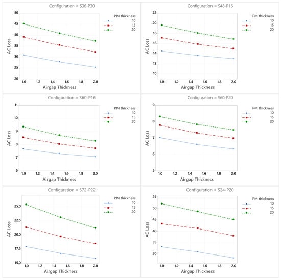
Figure 4.
AC losses (kW) for the PM-to-airgap ratio study.
A similar trend across all the motors is shown in Figure 4. The overall trend shows that the AC losses are minimised at thinner PM and thicker (wider) airgaps. This reflects the reduced airgap flux density and less flux leakage into the slot opening. Conversely, at 20 mm of PM thickness and the narrowest airgap of 1 mm, the motors experience the highest AC losses. The output power variation for each design is shown in Figure 5.
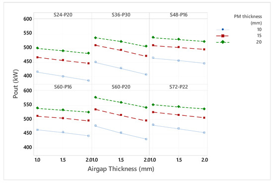
Figure 5.
Output (kW) for the PM-to-airgap ratio study.
Using MATLAB statistical analysis features, a statistical analysis is added in Table 3, where the correlation between the airgap thickness and the PM thickness is analysed in comparison to the AC losses. The airgap thickness has a strong negative correlation to the AC losses, which means that bigger airgaps lead to lower losses. The PM thickness, on the other hand, has a very strong positive correlation to the AC losses. Hence, bigger magnets would lead to a stronger airgap field and, hence, higher flux density in the slot and an elevated AC loss. The main advantage of this analysis is that it represents a generic relation between the AC losses and the airgap and PM thickness that can be extended to other motors.
Table 3.
Correlation analysis of airgap thickness and PM thickness with the AC losses.
3.3. Approach C: Stranding and Depth
A common practice to minimise the AC losses is to use multi-strands, as well as to push the winding away from the slot opening [17]. Therefore, the study is established such that the number of strands is varied, with 1, 10, 25, 50, and 100 strands, and the depth ratio of the winding is 100%, 90%, 80%, 70%, and 60%. Here, 100% refers to the windings filling the whole slot, and 60% indicates that 40% of the winding depth starting from the slot opening is empty. Figure 6 can be referred to for a visual representation of these variations. It may be noted that the turn diameter needs to be adjusted to accommodate the winding effectively. The results of this will be further discussed later in this subsection.
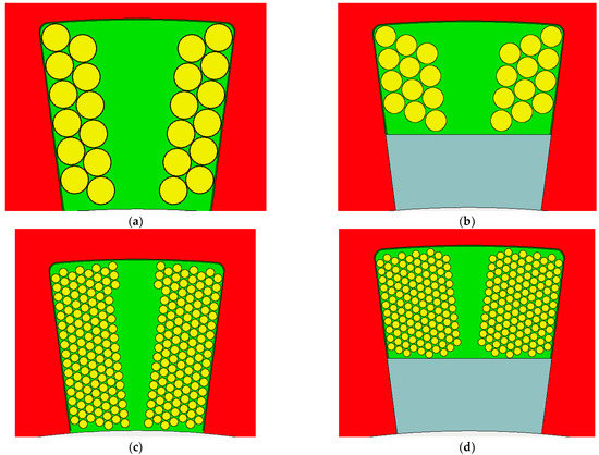
Figure 6.
Visual representation of winding stranding and depth for the S24-P20 as an example, (a) single strand with 100% depth ratio, (b) single strand with 60% depth ratio, (c) multi-strands with 100% depth ratio, and (d) multi-strands with 60% depth ratio.
For this analysis, and using the Motor-CAD interface, the arrangement of the winding strands is set to a bundle ratio of 0.5, which means that, for each turn, the strands are arranged such that the bundle of strands has a rectangle-like packing arrangement and, thus, the bundle factor is 0.5. The bundle factor can be defined as the ratio between the width and height of a bundle of strands that represent one turn. In fact, this is a very critical factor, as the exact positioning of the strands can significantly change the losses. For a fair comparison, this bundle factor is fixed at 0.5 for all the designs. Indeed, for each motor for this stranding analysis, 25 different simulations and designs were considered. The result of this study is summarised in Table 4, while a plot of the AC to DC loss ratio is depicted in Figure 7 and Figure 8.
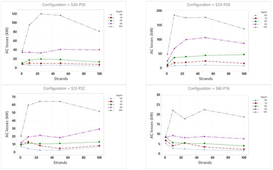
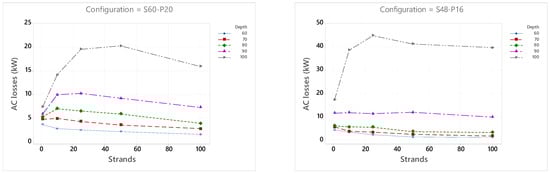
Figure 7.
Stranding effect on the AC/DC loss ratio.
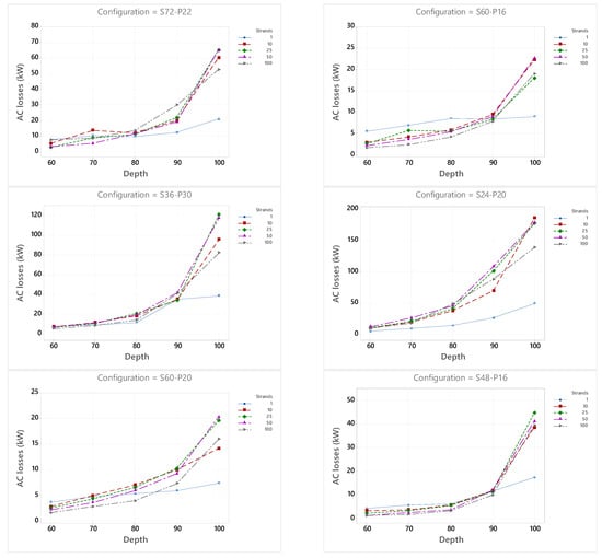
Figure 8.
Stranding effect on AC loss map.
Table 4.
AC losses (kW) for the stranding losses.
Table 4.
AC losses (kW) for the stranding losses.
| Depth (%) | Strands | S60-P20 | S48-P16 | S60-P16 | S72-P22 | S24-P20 | S36-P30 |
|---|---|---|---|---|---|---|---|
| 100 | 1 | 7.4 | 17.3 | 8.9 | 20.9 | 49.5 | 38.8 |
| 90 | 1 | 5.9 | 11.6 | 8.4 | 12.4 | 26.3 | 35.3 |
| 80 | 1 | 5.3 | 6.1 | 8.5 | 9.7 | 13.9 | 11.6 |
| 70 | 1 | 4.8 | 5.7 | 6.9 | 10.4 | 9.5 | 9.2 |
| 60 | 1 | 3.7 | 4.3 | 5.5 | 7.8 | 4.6 | 7.8 |
| 100 | 10 | 14.1 | 38.5 | 22.2 | 60.0 | 186.2 | 95.7 |
| 90 | 10 | 9.9 | 11.8 | 9.4 | 19.9 | 69.6 | 35.3 |
| 80 | 10 | 7.0 | 5.7 | 5.8 | 12.0 | 37.6 | 18.1 |
| 70 | 10 | 4.9 | 3.8 | 4.2 | 13.7 | 19.7 | 11.7 |
| 60 | 10 | 2.8 | 3.4 | 2.9 | 5.3 | 9.7 | 7.3 |
| 100 | 25 | 19.5 | 44.7 | 17.9 | 64.9 | 177.6 | 120.7 |
| 90 | 25 | 10.2 | 11.3 | 8.3 | 21.8 | 101.0 | 34.1 |
| 80 | 25 | 6.5 | 5.6 | 5.5 | 11.3 | 41.1 | 20.7 |
| 70 | 25 | 4.3 | 3.4 | 5.7 | 8.8 | 21.1 | 10.8 |
| 60 | 25 | 2.5 | 2.3 | 2.6 | 3.0 | 10.4 | 6.7 |
| 100 | 50 | 20.2 | 41.1 | 22.6 | 64.9 | 178.9 | 117.3 |
| 90 | 50 | 9.2 | 11.9 | 8.9 | 19.0 | 108.2 | 41.8 |
| 80 | 50 | 5.9 | 3.7 | 5.4 | 11.6 | 45.7 | 19.5 |
| 70 | 50 | 3.6 | 2.5 | 3.6 | 5.3 | 26.2 | 11.2 |
| 60 | 50 | 2.2 | 1.3 | 2.2 | 3.2 | 11.9 | 7.0 |
| 100 | 100 | 15.9 | 39.5 | 18.9 | 52.4 | 139.2 | 82.2 |
| 90 | 100 | 7.3 | 9.9 | 7.8 | 29.8 | 87.8 | 41.1 |
| 80 | 100 | 3.9 | 3.3 | 4.2 | 13.5 | 48.5 | 14.1 |
| 70 | 100 | 2.8 | 1.8 | 2.4 | 8.7 | 17.8 | 8.5 |
| 60 | 100 | 1.6 | 1.2 | 1.7 | 7.5 | 9.3 | 5.4 |
As these motors have a common design characteristic of open slots, the losses at 100% depth are very high; this is specifically very dominant in the case of multi-strands. This can be visually understood by examining Figure 9, where more strands are subjected to more flux lines and higher flux densities near the slot opening compared to having one strand. Nevertheless, pushing these multi-strands back in the slot can reduce the AC losses 14-fold, as in the case of the S48-P16 motor. It should be noted that the operating frequency of these motors is in the range of 200 Hz to 500 Hz and, thus, it is not very high compared to some other high-speed motors, where frequencies can reach up to 2000 Hz. Thus, for the machines studied, the dominant effects are the proximity losses and flux leakage, rather than the skin effect.
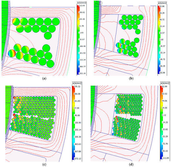
Figure 9.
The S24−P20 stranding results: (a) 1 strand, 100% depth, 48.5 kW, (b) 1 strand, 60% depth, 4.6 kW, (c) 10 strand, 100% depth, 186.2 kW, and (d) 10 strand, 60% depth, 9.7 kW.
Even with one strand, the AC losses can be reduced from 40% to 90%, when pushing the winding depth to 60%. However, this usually comes at the cost of higher DC losses, since less area is available for the winding, as thinner cross-section areas are used. However, the results for the one strand with the range of 80% to 60% depth seem very promising. Referring to the wire diameters from Table 1, it might be a manufacturing necessity to use multi-strands. Therefore, for this open slot, high airgap flux density design, a careful placement of the windings should be considered [28]. An additional advantage that comes from pushing the winding back is the possibility to use the created space for slot cooling channels in that area [42].
In Table 5, a correlation analysis is implemented to study the relationship between the AC losses, winding stranding, and coil depth. Reconfirming the previous conclusions, the depth of the winding is critical in reducing the AC losses. A very high positive correlation exists between the AC winding and how far the windings are pushed away from the slot opening. Therefore, the higher the value of depth, the more the AC losses are set to increase, and vice versa. However, the impact of the stranding of the winding turns has a weak correlation.
Table 5.
Correlation analysis of the slot opening parameter and AC losses.
3.4. Approach D: Slot Opening
This proposed method changes the slot opening from open to closed. Changing the design of the motors to be a closed slot design has the benefit of pushing the winding away from the slot opening, as well as potential improvements on the torque ripple and PM losses.
Three design parameters are taken into consideration. The first aspect is the slot opening width, the second is the slot opening tip depth, and finally the angle of the slot opening sides is considered, as depicted in Figure 10.
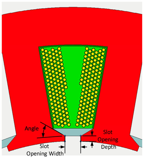
Figure 10.
The slot opening dimensional parameters.
For each of the factors, three operating points are tested. Therefore, for each motor, a total of 27 design variations are generated. The range and the nominal values for each are listed in Table 6. The slot openings are simulated at 0.5, 0.7, and 0.9 of the nominal fully open design. The slot tip depth is 0.04, 0.08, or 0.12 of the nominal overall slot depth. Finally, the angles of the slot inclination are set to 0.0°, 22.5°, and 45.0°.
Table 6.
Design aspects and performance indicators.
The AC losses in kW are listed in Table 7. Each design variation has an ID, and the open slot design has an ID of ‘0’. The AC losses show a remarkable reduction due to the change of slot opening. Indeed, the losses are halved for four motors, namely S48-P16, S72-P22, S36-P30, and S24-P20.
Table 7.
AC losses (kW) for the slot opening analysis.
The ratio of AC to DC losses is mapped as an interval plot in Figure 11a, and the AC losses in kW interval plots are shown in Figure 11b. It is clear that for S24-P20 and S36-P30 there is the most variation in change in the AC losses. This reflects the fact that, in these concentrated winding motors, the change of slot opening parameters have a major effect on the slot harmonics and flux leakage.
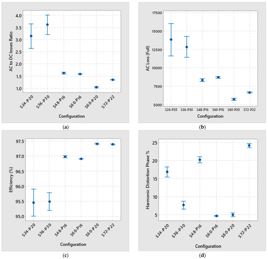
Figure 11.
Interval plot of opening study: (a) AC to DC loss ratio, (b) AC losses in (kW), (c) Efficiency (%), and (d) THD (5).
The interval plot for the efficiency is shown in Figure 11c, and the total harmonic distortion is shown in Figure 11d. The AC losses have a large variation for S24-P20 and S36-P30, hence, there is a similar trend in the efficiency interval plot. More insights can be deduced from the current density plots in Figure 12.
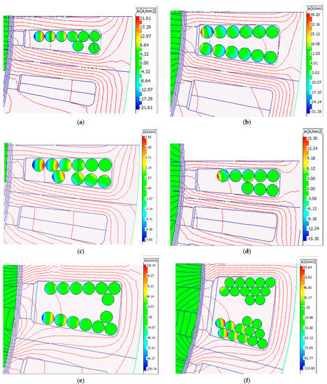
Figure 12.
Slot open current density map results for solution ID 27: (a) S60−P20, PAC 5.3 kW, 27% reduction, (b) S48−P16, PAC 8.6 kW, 50% reduction, (c) S60−P16, PAC 8.6 kW, 3% reduction, (d) S72−P22, PAC 7.1 kW, 66% reduction, (e) S36−P30, PAC 11.0 kW, 78% reduction, and (f) S24−P20, PAC 10.6 kW, 72.6% reduction.
Additionally, a statistical correlation analysis is carried out as shown in Table 8. The correlation between the three varied parameters and the AC losses is analysed. The negative correlation between the teeth tips angle indicates that higher values of the teeth tips’ angle led to lower AC losses. A similar negative correlation also exists with the tooth tip depth. Thus, the thicker the tooth tips and, as a result, the farther away the coils are pushed away from the slot opening, the lower the AC losses. Conversely, the slot opening has a positive correlation with the AC losses. The wider the slot opening, the higher the AC losses. Consequently, the overall recommendation to have lower levels of AC losses is to decrease the slot opening and increase the teeth tips’ depth and angle.
Table 8.
Correlation analysis of the slot opening parameter and AC losses.
In general, the proposed method of optimising the slot opening managed to reduce the AC losses by different magnitudes for different motor designs. Despite the benefits and reduction in AC losses, the proposed technique might also have some negative consequences, such as increased torque ripple and introducing additional saturation in the tooth tips. Therefore, it is highly recommended to thoroughly explore the slot opening design as a means of effectively reducing the AC winding losses, unless the open slot design is a requirement for ease of manufacturing, winding, and assembly.
3.5. Approach E: Semi-Magnetic Wedges
The magnetic or semi-magnetic wedges (SM-W) have relative permeabilities that can range from 2 to 20 [43]. Indeed, SM-W have been widely implemented as a method of reducing the PM losses [39], but also in machine windings [43]. The SM-Ws are considered for AC winding loss reduction. A relative permeability of 8 is assumed, although the losses associated with the wedges are not quantified. The motors simulated for this analysis are all at 90% depth ratio, where the slot wedge occupies the remaining 10% depth of each slot. Therefore, the absolute thickness of each motor’s wedge is different, and the number of strands included in this study is 1, 10, 25, 50, and 100. The AC losses, output power, efficiency, and torque ripples are summarised in Table 9, whereas the eddy current map at the same time instant and for the 25-strand designs are shown in Figure 13.
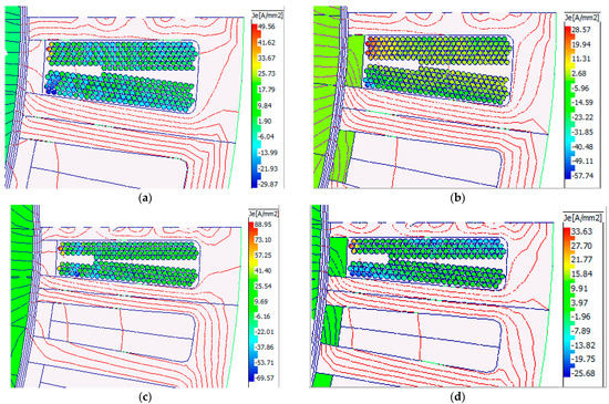
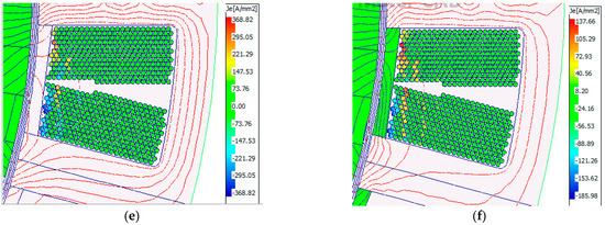
Figure 13.
Eddy current density for the SM-W for the 25-strand designs. (a) S48-P16, no SM-W, Pac 11.3 kW, (b) S48-P16, with SM-W, Pac 8.2 kW, (c) S72-P22, no SM-W, Pac 21.8 kW, (d) S72-P22, with SM-W, Pac 14.5 kW, (e) S24-P20, no SM-W, Pac 101.0 kW, (f) S24-P20, with SM-W, Pac 44.0 kW.
Table 9.
Semi-magnetic slot wedge results.
Table 9.
Semi-magnetic slot wedge results.
| Strands | AC Losses (kW) | Output Power (kW) | Efficiency (%) | Torque Ripple (%) | ||||
| SM-1 * | SM-8 | SM-1 | SM-8 | SM-1 | SM-8 | SM-1 | SM-8 | |
| S60-P20 | ||||||||
| 1 | 7.4 | 5.5 | 540.9 | 534.5 | 97.3 | 97.3 | 5.1 | 1.7 |
| 10 | 9.9 | 9.7 | 535.4 | 520.0 | 96.8 | 96.6 | 7.7 | 1.8 |
| 25 | 10.2 | 10.3 | 535.5 | 520.7 | 96.8 | 96.6 | 7.6 | 1.6 |
| 50 | 9.2 | 6.3 | 535.4 | 519.3 | 96.8 | 97.2 | 7.8 | 1.5 |
| 100 | 7.3 | 5.7 | 534.0 | 519.3 | 97.0 | 97.3 | 7.4 | 1.5 |
| S48-P16 | ||||||||
| 1 | 17.3 | 10.2 | 514.4 | 485.9 | 96.4 | 96.6 | 22.9 | 22.0 |
| 10 | 11.8 | 10.1 | 514.1 | 483.9 | 96.4 | 96.6 | 25.8 | 21.4 |
| 25 | 11.3 | 8.2 | 515.4 | 485.2 | 96.5 | 97.0 | 23.6 | 20.7 |
| 50 | 11.9 | 8.8 | 515.4 | 484.1 | 96.4 | 96.9 | 23.6 | 21.7 |
| 100 | 9.9 | 3.9 | 514.1 | 485.9 | 96.6 | 97.7 | 25.2 | 18.1 |
| S60-P16 | ||||||||
| 1 | 8.9 | 8.3 | 521.2 | 488.5 | 96.9 | 96.8 | 1.7 | 2.6 |
| 10 | 9.4 | 10.1 | 515.2 | 486.1 | 96.8 | 96.4 | 1.9 | 2.9 |
| 25 | 8.3 | 9.1 | 515.2 | 482.8 | 96.9 | 96.6 | 1.9 | 2.9 |
| 50 | 8.9 | 5.8 | 515.2 | 481.1 | 96.8 | 97.2 | 1.8 | 1.3 |
| 100 | 7.8 | 5.0 | 514.7 | 481.1 | 96.9 | 97.2 | 2.1 | 1.3 |
| S72-P22 | ||||||||
| 1 | 20.9 | 8.5 | 530.4 | 494.7 | 96.5 | 97.0 | 1.6 | 2.0 |
| 10 | 19.9 | 13.7 | 527.8 | 494.9 | 95.2 | 96.1 | 2.9 | 2.5 |
| 25 | 21.8 | 14.5 | 527.5 | 494.5 | 94.8 | 95.9 | 3.1 | 2.6 |
| 50 | 19.0 | 12.2 | 528.3 | 495.2 | 95.3 | 96.3 | 3.3 | 2.9 |
| 100 | 29.8 | 14.8 | 527.6 | 493.2 | 93.4 | 95.7 | 2.6 | 2.0 |
| S24-P20 | ||||||||
| 1 | 49.5 | 17.5 | 474.0 | 455.2 | 92.9 | 94.9 | 0.7 | 2.6 |
| 10 | 69.6 | 35.7 | 467.7 | 450.2 | 85.5 | 91.4 | 2.6 | 3.3 |
| 25 | 101 | 44 | 464.9 | 449.8 | 80.7 | 89.8 | 3.8 | 3.4 |
| 50 | 108.2 | 47.8 | 474.8 | 453.7 | 80.1 | 89.3 | 4.5 | 2.2 |
| 100 | 87.8 | 38.6 | 474.8 | 453.7 | 82.9 | 90.8 | 4.7 | 2.2 |
| S36-P30 | ||||||||
| 1 | 38.8 | 13.7 | 494.1 | 474.1 | 91.5 | 95.3 | 5.2 | 3.1 |
| 10 | 35.3 | 25.7 | 494.1 | 461.9 | 91.5 | 93.1 | 5.2 | 6.9 |
| 25 | 34.1 | 25.5 | 493.8 | 461.4 | 91.6 | 93.1 | 5.0 | 7.2 |
| 50 | 41.8 | 29.3 | 508.2 | 477.5 | 90.4 | 92.5 | 1.5 | 2.2 |
| 100 | 41.1 | 18.4 | 480.2 | 449.9 | 90.2 | 94.3 | 4.3 | 4.4 |
* Here, SM-1 is a non-magnetic wedge; SM-8 is a magnetic wedge with a relative permeability of 8.
The semi-magnetic wedges are most effective for the concentrated winding type, as these windings tend to have more harmonics near the edge, which are redirected away by the wedges. In Table 8, the SM-1 refers to the wedge with a relative permeability of 1, i.e., the normal operation, whereas the SM-8 is for the semi-magnetic wedges as prescribed. Magnetic wedges are indeed more effective than non-magnetic ones. Yet, contrary to non-magnetic wedges, they tend to increase the tooth tips’ flux leakage, thus, decreasing the output power in the process. The efficiency is increased with the use of magnetic wedges due to the reduced AC losses. As mentioned earlier in the introduction of this section, magnetic wedges also have a positive effect on reducing the PM losses, which further improves the motor’s overall performance and thermal performance.
4. Discussion
A quantitative comparison for the percentage change in the AC winding losses is compiled in Table 10, and a similar comparison for the change in output power caused by each AC loss reduction technique is listed in Table 11.
All of the proposed methods managed to reduce the AC losses. The PM magnetisation method is one of the least effective techniques that managed to reduce the AC losses, with a maximum reduction of 25.4% and an average of 4.7%. On the other hand, for the distributed winding motors S60-P20 and S48-P16 and the fractional slot motor S60-P16, the effect is reversed, and the losses increase by between 1.3% and 14.6%.
By modifying the PM-to-airgap thickness ratio, the AC losses can be significantly reduced when smaller magnets and bigger airgaps are introduced. Indeed, the AC losses can be minimised by a factor of between 17.8% and 58.3% with a smaller magnet volume. Using stronger magnets would increase the AC losses, despite the possible benefits of higher airgap flux density.
Winding depth and stranding can be one of the most effective methods of reducing AC losses by up to 93.2%. Nonetheless, very careful analysis at different copper depth levels and the number of strands should be considered, otherwise it may increase the AC losses. Increasing the number of strands alone without pushing the winding away from the slot opening could lead to higher AC losses. However, stranding can be a necessity for this motor design, since it has a large turn diameter. Among all the design variations, the average reduction in AC losses by stranding and depth is not very high. However, the maximum achievable reduction through this method is very promising for all the motors. The maximum reduction in the AC losses is at least 79.2%, and can go up to 93.2%.
Slot opening and the SM-W also look very promising in mitigating these AC losses. The manipulation of the slot opening can enhance the overall motor performance and reduces the AC losses significantly. Although the effect is varied, depending on the different slot/pole combinations, on average the reduction is 49.1% and 26.5% for the slot opening and magnetic wedge, respectively. The fractional slot motor S60-P16 shows the least reduction in AC losses; by modifying the slot opening at 6.1%, this can increase up to 43.8% with the introduction of the magnetic wedges. Conversely, slot opening variation for the concentrated winding motors, i.e., S36-P30 and S24-P20, have an average reduction in AC losses of 66.9% and 79.7% respectively, which is very promising in terms of electromagnetic and thermal performance.
Table 10.
Percentage change of AC losses compared to initial design quantitative comparison *.
Table 10.
Percentage change of AC losses compared to initial design quantitative comparison *.
| Change Range [Max, Min] Average | S60-P20 (Distributed) | S48-P16 (Distributed) | S60-P16 (Fractional) | S72-P22 (Fractional) | S24-P20 (Concentrated) | S36-P30 (Concentrated) | Overall |
|---|---|---|---|---|---|---|---|
| Magnetisation direction | [1.3, 1.3] 1.3 | [9.8, 9.1] 14.5 | [4.5, 14.6] 9.6 | [−25.4, −21.5] −23.4 | [−12.9, −6.6] −9.8 | [−21.9, −18.3] −20.1 | Minor- Average |
| PM/AG ratio | [−17.6, 8.0] −5.1 | [−24.9, 13.5] −7.6 | [−20.2, 5.3] −9.1 | [−24.1, 21.4] −4.4 | [−58.3, −23.3] −40.9 | [−34.6, 16.5] −9.9 | Minor- Average |
| Depth and Stranding | [−79.2, 62.3] −5.8 | [−93.1, 58.4] −32.6 | [−80.9, 153.9] −9.9 | [−85.6, 10.5] −4.7 | [−93.2, 73.8] −14.6 | [−86.1, 11.1] −16.3 | Major- Average |
| Slot Opening | [−32.9, −18.6] −25.7 | [−60.2, −50.2] −51.9 | [−6.1, 5.4] −2.2 | [−69.9, −66.3] −68.1 | [−90, −63.5] −79.7 | [−78.1, −50.4] −66.9 | Major- Average |
| Magnetic wedge | [−28.6, 33.8] −2.6 | [−77.5, −41.0] −52.4 | [−43.8, 13.5] −13.9 | [−59.3, −29.2] −39.0 | [−74.3, −29.7] −46.0 | [−64.7, −24.5] −42.0 | Average |
| Overall | Minor- Average | Average | Minor- Average | Average | Major- Average | Major | Average Major |
* Negative values indicate a reduction in AC losses, and positive values indicate an increase in AC losses.
Despite the prementioned benefits and reduction in AC losses, the proposed techniques might also have some negative effects. One aspect of the key performance parameter is exemplified in Table 10 as the percentile change on the output power. The change in the slot opening might in fact increase the output power. For example, in the case of motor S24-P20, the output power can increase up to 3.8%. The PM-to-airgap ratio can also increase the output power by 3.7% for the S24-P20 motor. The PM magnetisation directions and the SM-wedge have a relatively strong negative effect on the output power. Thus, both of these methods should be treated carefully, although PM losses can be reduced by a large margin through these two methods. The stranding has a very minor effect in the majority of the studied cases. However, as has been discussed, the stranding and pushing of the winding can increase the DC losses.
Table 11.
Percentage change of output power compared to the initial design quantitative comparison for the AC loss reduction analysis *.
Table 11.
Percentage change of output power compared to the initial design quantitative comparison for the AC loss reduction analysis *.
| Change Range [Max, Min] Average | S60-P20 (Distributed) | S48-P16 (Distributed) | S60-P16 (Fractional) | S72-P22 (Fractional) | S24-P20 (Concentrated) | S36-P30 (Concentrated) | Overall |
|---|---|---|---|---|---|---|---|
| Magnetisation direction | [−15.0, −11.0] −13.0 | [−7.0, −4.2] −5.6 | [−7.9, −4.9] −6.4 | [−10.0, −7.0] −8.5 | [−11.2, −7.8] −9.5 | [−21.8, −18.4] −20.1 | Average Negative |
| PM/AG ratio | [−21.3, 5.5] −6.8 | [−15.5, 1.6] −6.1 | [−16.6, 1.8] −6.3 | [−16.3, 2.0] −6.0 | [−19.7, 3.7] −6.6 | [−21.2, 3.1] −7.3 | Average Negative |
| Depth and Stranding | [−20.5, 0.1] −2.4 | [−4.7, −0.1] −2.8 | [−5.0, 0.0] −3 | [−5.3, −0.1] −2.9 | [−2.1, 1.2] −1.1 | [−7.3, 0.0] −4.7 | Minor Negative |
| Slot Opening | [−0.4, 1.1] 0.4 | [−4.1, −0.2] −1.5 | [−3.4, −0.1] −1.3 | [−3.8, 0.0] −1.5 | [1.3, 3.8] 2.7 | [0.8, 3.6] 2.3 | Minor Positive |
| Magnetic wedge | [−4.7, −1.9] −4.1 | [−7.8, −7.4] −7.6 | [−9.1, −7.7] −8.5 | [−8.7, −8.3] −8.4 | [−5.3, −4.2] −4.7 | [−11.8, −6.4] −8.8 | Average Negative |
| Overall | Minor Negative | Minor Negative | Minor Negative | Minor Negative | Minor Negative | Average Negative | Minor Negative |
* Negative values indicate a reduction in output power, and positive values is an increase in output power.
5. Conclusions
In this paper, the winding AC losses were investigated for six motors which cover three different random winding configurations. Distributed, fractional slot, and concentrated windings were included, and motors with pole numbers from 16 to 36 and slot numbers from 24 to 72 were investigated to cover a wide range of motor designs. Five methods to mitigate these losses were proposed and applied to the proposed motors. These include optimising the airgap-to-PM ratio, PM magnetisation direction, wire stranding, pushing the coils away from opening, reshaping the slot opening, and adding a magnetic slot wedge. The analysis was executed through a finite element method-based software and the results were later discussed in terms of quantitative comparisons. Hence, this extensive study should serve as a reference recommendation for the optimum motor design when AC winding losses are a concern.
In conclusion, there is a potential for a major cut in AC losses of concentrated winding motors by all the proposed methods. Amongst them, winding depth and stranding are the most effective, followed by changing the slot opening geometry and adding the magnetic slot wedge. The fractional slot winding AC losses can be fairly mitigated by the magnetic slot wedge and the change from open to closed slot opening, as well as by pushing the winding away from the airgap and stranding of the turns. Distributed winding losses also have a large margin of reduction through the proposed techniques. Finally, the proposed techniques can reduce AC losses by a very large margin of up to 93%. This provides the additional advantage of reducing the cooling system weight and size, which is critical in aerospace applications. It is recommended to consider the problem as a multi-aspect matter, as while reducing the AC losses, the efficiency, PM losses, stator core losses, harmonics content, output power, and torque ripples should all be monitored and maintained.
Author Contributions
Conceptualization, A.H., S.N. and G.V.; methodology, A.H.; software, A.H.; validation, A.H.; formal analysis, A.H.; investigation, A.H.; resources, A.H., M.G. and C.G.; data curation, A.H.; writing—original draft preparation, A.H.; writing—review and editing, A.H., P.H.C., S.N. and G.V.; visualization, A.H.; supervision, S.N., P.H.C. and M.G.; project administration, M.G. and C.G.; funding acquisition, C.G. and M.G. All authors have read and agreed to the published version of the manuscript.
Funding
This work is funded by the INNOVATIVE doctoral programme. The INNOVATIVE programme is partially funded by the Marie Curie Initial Training Networks (ITN) action (project number 665468) and partially by the Institute for Aerospace Technology (IAT) at the University of Nottingham.
Data Availability Statement
Not applicable.
Conflicts of Interest
The authors declare no conflict of interest.
References
- Anderson, A.D.; Renner, N.J.; Wang, Y.; Agrawal, S.; Sirimanna, S.; Lee, D.; Banerjee, A.; Haran, K.; Starr, M.J.; Felder, J.L. System Weight Comparison of Electric Machine Topologies for Electric Aircraft Propulsion. In Proceedings of the 2018 AIAA/IEEE Electric Aircraft Technologies Symposium, EATS 2018, Cincinnati, OH, USA, 12–14 July 2018. [Google Scholar] [CrossRef]
- Ghoneim, W.A.M.; Hebala, A.; Ashour, H.A. Sensitivity Analysis of Parameters Affecting the Performance of Radial Flux Low-Speed PMSG. In Proceedings of the 2018 XIII International Conference on Electrical Machines (ICEM), Alexandroupoli, Greece, 3–6 September 2018; pp. 968–974. [Google Scholar] [CrossRef]
- Hebala, A.; Ghoneim, W.A.M.; Ashour, H.A. Detailed Design Procedures for PMSG Direct-Driven by Wind Turbines. J. Electr. Eng. Technol. 2019, 14, 251–263. [Google Scholar] [CrossRef]
- Atkinson, G.J.; Mecrow, B.C.; Jack, A.G.; Atkinson, D.J.; Sangha, P.; Benarous, M. The analysis of losses in high-power fault-tolerant machines for aerospace applications. IEEE Trans. Ind. Appl. 2006, 42, 1162–1170. [Google Scholar] [CrossRef]
- Dimier, T.; Cossale, M.; Wellerdieck, T. Comparison of stator winding technologies for high-speed motors in electric propulsion systems. In Proceedings of the 2020 International Conference on Electrical Machines (ICEM), Gothenburg, Sweden, 23–26 August 2020; pp. 2406–2412. [Google Scholar] [CrossRef]
- Silber, S.; Klammer, B.; Kaspar, K. Efficient Method for Simulation of AC Losses in Permanent Magnet Synchronous Machines. In Proceedings of the 2020 10th International Electric Drives Production Conference (EDPC), Ludwigsburg, Germany, 8–9 December 2020. [Google Scholar] [CrossRef]
- Gerada, D.; Mebarki, A.; Brown, N.L.; Gerada, C.; Cavagnino, A.; Boglietti, A. High-speed electrical machines: Technologies, trends, and developments. IEEE Trans. Ind. Electron. 2014, 61, 2946–2959. [Google Scholar] [CrossRef]
- Nuzzo, S.; Barater, D.; Gerada, C.; Vai, P. Hairpin Windings: An Opportunity for Next-Generation E-Motors in Transportation. IEEE Ind. Electron. Mag. 2021, 2–10. [Google Scholar] [CrossRef]
- Choi, M.; Choi, G. Modeling, investigation, and mitigation of ac losses in ipm machines with hairpin windings for ev applications. Energies 2021, 14, 8034. [Google Scholar] [CrossRef]
- Park, S.H.; Lee, E.C.; Lee, G.J.; Kwon, S.O.; Lim, M.S. Effect of pole and slot combination on the ac joule loss of outer-rotor permanent magnet synchronous motors using a high fill factor machined coil. Energies 2021, 14, 3073. [Google Scholar] [CrossRef]
- Arzillo, A.; Nuzzo, S.; Braglia, P.; Franceschini, G.; Barater, D.; Gerada, D.; Gerada, C. An analytical approach for the design of innovative hairpin winding layouts. In Proceedings of the 2020 International Conference on Electrical Machines (ICEM), Gothenburg, Sweden, 23–26 August 2020; pp. 1534–1539. [Google Scholar] [CrossRef]
- Sullivan, C.R. Optimal choice for number of strands in a litz-wire transformer winding. IEEE Trans. Power Electron. 1999, 14, 283–291. [Google Scholar] [CrossRef]
- Qiu, Z.; Chen, Y.; Liu, X.; Zhang, L.; Cheng, H. Evaluation and comparison of sideband harmonics and acoustic responses with continuous and discontinuous PWM strategies in permanent magnet synchronous motor for electric vehicles. Int. J. Hydromechatron. 2022, 5, 109. [Google Scholar] [CrossRef]
- Volpe, G.; Popescu, M.; Di Leonardo, L.; Xue, S. Efficient Calculation of PWM AC Losses in Hairpin Windings for Synchronous BPM Machines. In Proceedings of the 2021 IEEE International Electric Machines & Drives Conference (IEMDC), Hartford, CT, USA, 17–20 May 2021; pp. 10–14. [Google Scholar] [CrossRef]
- Winterborne, D.; Jordan, S.; Sjoberg, L.; Atkinson, G. Estimation of AC copper loss in electrical machine windings with consideration of end effects. In Proceedings of the 2020 International Conference on Electrical Machines (ICEM), Gothenburg, Sweden, 23–26 August 2020; pp. 847–853. [Google Scholar] [CrossRef]
- Morisco, D.P.; Rapp, H.; Iepure, I.L.; Mockel, A. Extended modelling approach of hairpin winding eddy current losses in high power density traction machines. In Proceedings of the 2020 International Conference on Electrical Machines (ICEM), Gothenburg, Sweden, 23–26 August 2020; pp. 874–880. [Google Scholar] [CrossRef]
- Volpe, G.; Popescu, M.; Marignetti, F.; Goss, J. AC winding losses in automotive traction e-machines: A new hybrid calculation method. In Proceedings of the 2019 IEEE International Electric Machines & Drives Conference (IEMDC), San Diego, CA, USA, 12–15 May 2019; pp. 2115–2119. [Google Scholar] [CrossRef]
- Volpe, G.; Popescu, M.; Marignetti, F.; Goss, J. Modelling AC Winding Losses in a PMSM with High Frequency and Torque Density. In Proceedings of the 2018 IEEE Energy Conversion Congress and Exposition (ECCE), Portland, OR, USA, 23–27 September 2018; pp. 2300–2305. [Google Scholar] [CrossRef]
- Katagiri, H.; Semba, K.; Sano, H.; Mimura, N.; Yamada, T. Fast calculation of AC copper loss for high speed machines by zooming method. IEEJ J. Ind. Appl. 2017, 6, 395–400. [Google Scholar] [CrossRef][Green Version]
- Lyu, J.; Chen, H.; Zhang, Y.; Du, Y.; Cheng, Q.S. Fast Simulation of Litz Wire Using Multilevel PEEC Method. IEEE Trans. Power Electron. 2020, 35, 12612–12616. [Google Scholar] [CrossRef]
- Hiruma, S.; Otomo, Y.; Igarashi, H. Eddy Current Analysis of Litz Wire Using Homogenization-Based FEM in Conjunction with Integral Equation. IEEE Trans. Magn. 2018, 54, 7001404. [Google Scholar] [CrossRef]
- Bardalai, A.; Gerada, D.; Golovanov, D.; Xu, Z.; Zhang, X.; Li, J.; Zhang, H.; Gerada, C. Reduction of Winding AC Losses by Accurate Conductor Placement in High Frequency Electrical Machines. IEEE Trans. Ind. Appl. 2020, 56, 183–193. [Google Scholar] [CrossRef]
- Simpson, N.; North, D.J.; Collins, S.M.; Mellor, P.H. Additive Manufacturing of Shaped Profile Windings for Minimal AC Loss in Electrical Machines. IEEE Trans. Ind. Appl. 2020, 56, 2510–2519. [Google Scholar] [CrossRef]
- Reddy, P.B.; Jahns, T.M.; El-Refaie, A.M. Impact of winding layer number and slot/pole combination on AC armature losses of synchronous surface PM machines designed for wide constant-power speed range operation. In Proceedings of the 2008 IEEE Industry Applications Society Annual Meeting, Edmonton, AB, Canada, 5–9 October 2008; pp. 1–8. [Google Scholar] [CrossRef]
- Gyselinck, J.; Dular, P.; Sadowski, N.; Kuo-Peng, P.; Sabariego, R.V. Homogenization of form-wound windings in frequency and time domain finite-element modeling of electrical machines. IEEE Trans. Magn. 2010, 46, 2852–2855. [Google Scholar] [CrossRef]
- Thomas, A.S.; Zhu, Z.Q.; Jewell, G.W. Proximity Loss Study In High Speed Flux-Switching Permanent Magnet Machine. IEEE Trans. Magn. 2009, 45, 4748–4751. [Google Scholar] [CrossRef]
- Selema, A.; Ibrahim, M.N.; Sergeant, P. Mitigation of High-Frequency Eddy Current Losses in Hairpin Winding Machines. Machines 2022, 10, 328. [Google Scholar] [CrossRef]
- Bardalai, A.; Gerada, D.; Xu, Z.; Gerada, C. AC loss Analysis in Winding of Electrical Machines with varying Strands-in-hand and Bundle Shapes. In Proceedings of the 2020 23rd International Conference on Electrical Machines and Systems (ICEMS), Hamamatsu, Japan, 24–27 November 2020; pp. 845–850. [Google Scholar] [CrossRef]
- Widmer, J.D.; Martin, R.; Mecrow, B.C. Precompressed and Stranded Aluminum Motor Windings for Traction Motors. IEEE Trans. Ind. Appl. 2016, 52, 2215–2223. [Google Scholar] [CrossRef]
- Bardalai, A.; Gerada, D.; Zou, T.; Degano, M.; Zhang, C. Comparison of AC Losses in the Winding of Electrical Machines with Fixed Strands Positions, Fixed Conductor Shapes and Random Winding. Energies 2022, 15, 5701. [Google Scholar] [CrossRef]
- Simpson, N.; Tighe, C.; Mellor, P. Design of high performance shaped profile windings for additive manufacture. In Proceedings of the 2019 IEEE Energy Conversion Congress and Exposition (ECCE), Baltimore, MD, USA, 29 September–3 October 2019; pp. 761–768. [Google Scholar] [CrossRef]
- Hebala, A.; Nuzzo, S.; Connor, P.H.; Giangrande, P.; Gerada, C.; Galea, M. Improved propulsion motor design for a twelve passenger all-electric aircraft. In Proceedings of the 2021 IEEE Workshop on Electrical Machines Design, Control and Diagnosis (WEMDCD), Modena, Italy, 8–9 April 2021; pp. 343–348. [Google Scholar] [CrossRef]
- Pechlivanidou, M.S.C.; Kladas, A.G. Litz wire strand shape impact analysis on AC losses of high-speed permanent magnet synchronous motors. In Proceedings of the 2021 IEEE Workshop on Electrical Machines Design, Control and Diagnosis (WEMDCD), Modena, Italy, 8–9 April 2021; pp. 95–100. [Google Scholar] [CrossRef]
- Van Der Geest, M.; Polinder, H.; Ferreira, J.A.; Zeilstra, D. Current sharing analysis of parallel strands in low-voltage high-speed machines. IEEE Trans. Ind. Electron. 2014, 61, 3064–3070. [Google Scholar] [CrossRef]
- Sullivan, C.R.; Zhang, R.Y. Simplified design method for Litz wire. In Proceedings of the 2014 IEEE Applied Power Electronics Conference and Exposition—APEC 2014, Fort Worth, TX, USA, 16–20 March 2014; pp. 2667–2674. [Google Scholar] [CrossRef]
- Guillod, T.; Huber, J.; Krismer, F.; Kolar, J.W. Litz wire losses: Effects of twisting imperfections. In Proceedings of the 2017 IEEE 18th Workshop on Control and Modeling for Power Electronics (COMPEL), Stanford, CA, USA, 9–12 July 2017. [Google Scholar] [CrossRef]
- Nan, X.; Sullivan, C.R. An equivalent complex permeability model for litz-wire windings. IEEE Trans. Ind. Appl. 2009, 45, 854–860. [Google Scholar] [CrossRef]
- Hamalainen, H.; Pyrhonen, J.; Nerg, J.; Talvitie, J. AC Resistance factor of litz-wire windings used in low-voltage high-power generators. IEEE Trans. Ind. Electron. 2014, 61, 693–700. [Google Scholar] [CrossRef]
- Hebala, A.; Nuzzo, S.; Connor, P.H.; Giangrande, P.; Gerada, C.; Galea, M. PM Halbach Arrays in Motors: Loss Reduction and Performance Improvements. In Proceedings of the 2020 23rd International Conference on Electrical Machines and Systems (ICEMS), Hamamatsu, Japan, 24–27 November 2020; pp. 710–715. [Google Scholar] [CrossRef]
- Brown, N.L.; Nuzzo, S.; Galea, M.; Gerada, C.; Gerada, D.; Mebarki, A. Damper cage loss reduction and no-load voltage THD improvements in salient-pole synchronous generators. In Proceedings of the 8th IET International Conference on Power Electronics, Machines and Drives (PEMD 2016), Glasgow, UK, 19–21 April 2016; p. 7. [Google Scholar] [CrossRef]
- Chu, W.Q.; Zhu, Z.Q. Optimal Split Ratio and Torque Comparison of Surface-Mounted Permanent Magnet Machines Having Inner or Outer Rotor. In Proceedings of the IET 6th IET International Conference on Power Electronics, Machines and Drives (PEMD 2012), Bristol, UK, 27–29 March 2012; pp. 2–7. [Google Scholar]
- Lindh, P.; Petrov, I.; Pyrhonen, J.; Scherman, E.; Niemela, M.; Immonen, P. Direct Liquid Cooling Method Verified with a Permanent-Magnet Traction Motor in a Bus. IEEE Trans. Ind. Appl. 2019, 55, 4183–4191. [Google Scholar] [CrossRef]
- Nuzzo, S.; Degano, M.; Galea, M.; Gerada, C.; Gerada, D.; Brown, N. Improved Damper Cage Design for Salient-Pole Synchronous Generators. IEEE Trans. Ind. Electron. 2017, 64, 1958–1970. [Google Scholar] [CrossRef]


Publisher’s Note: MDPI stays neutral with regard to jurisdictional claims in published maps and institutional affiliations. |
© 2022 by the authors. Licensee MDPI, Basel, Switzerland. This article is an open access article distributed under the terms and conditions of the Creative Commons Attribution (CC BY) license (https://creativecommons.org/licenses/by/4.0/).