Abstract
The crane track of a steel structure workshop was installed eccentrically, and the crane operation caused a large deflection of the crane beam, requiring reinforcement measures. The finite element model of the crane beam was established by Midas Gen finite element software, and the maximum stress, deflection, and the stress amplitude of 9 m and 12 m steel crane beam under different track eccentricity values were analyzed. The results show that when there is no brake truss, the maximum stress and deflection of the crane beam will increase greatly under the action of eccentric loading. On the contrary, a brake truss can effectively reduce the adverse effect of eccentric loading; the fatigue strength of crane beam cannot be controlled under eccentric rail loading. The reason why steel crane beam is sensitive to track eccentricity is that its torsional stiffness is too small. As a reinforcement measure, welding angle steel or steel plate lower on the crane beam flange, forming a box section, can effectively increase the torsional stiffness of the crane beam; the residual stress can then be effectively reduced by applying intermittent welding and reinforcement using the same material.
1. Introduction
Steel crane beam is the focus of plant design and construction, and the design limit and construction quality requirements are higher than for ordinary beam [1]. This is because under the normal conditions of crane operation, the deflection of the crane beam is the main reason for the noise of the crane, the big wheel gnawing the rail, the gap between the rail and the crane beam, and the poor walking of the crane [2]. In the construction process of the crane workshop, due to the existence of construction errors, the upper rail of the crane beam cannot be completely centered. When the crane is running, it will produce transverse torque on the crane beam. This torque will inevitably cause the increase in stress and deflection of the crane beam [3,4]. When the eccentricity of the crane beam track center exceeds the limit, the strength and deflection of the crane beam should be calculated according to the actual eccentricity, and corresponding reinforcement measures should be taken.
How to strengthen the crane beam with the increase in deflection has become an urgent problem to be solved. Some scholars have conducted in-depth research in this direction, achieving particular results. Yu, Zhou, and Wu used ANSYS to analyze the strength, deflection, and fatigue of intermediate working crane beam under eccentric loading, suggesting reinforcement measures [5]. Zheng et al. used ANSYS to analyze the mechanical properties of intermediate working crane under eccentric track load, compared and analyzed the effects before and after reinforcement, and calculated its influence on the deflection of crane beam [6]. Among the available software, ANSYS is a large general finite element analysis software, which can simulate engineering and which has a wide range of applications in various fields. Zhao et al. studied the steel crane beam angle mutation-bearing insert plate end-fatigue performance, using the method of VCCT and mesh partition technology to implement the fatigue crack propagation simulation, called the clear fatigue crack propagation model, combining it with the S-N curve and the probability fracture mechanics method to establish the probability damage tolerance analysis method in order to analyze fatigue performance [7]. Tong studied reasonable methods for the stability design of steel crane beams, analyzed the problems of the existing design methods, proposed a new formula for stable washing, compared it with the finite element results, confirmed its good accuracy, and obtained more reasonable calculation results [8].
At present, the analysis by scholars of crane beam under eccentric track load is aimed at an intermediate working system. Intermediate working crane beams are generally controlled by bearing capacity, without checking fatigue, and brake trusses or brake plates are rarely used [9,10]. The calculation of heavy duty crane beam not only requires multiplication by a larger dynamic coefficient, but also that the fatigue calculation be stricter. Angle steel or steel plate is generally used to weld the original crane beam to improve the section and torsional stiffness of the crane. Residual stress and deformation will occur during welding [11,12,13,14], which will affect the strength and stiffness of crane beam [15,16,17,18]. Measures must be taken to reduce residual stress. There is no relevant research on the distribution of residual stress in crane beam reinforcement.
In this paper, the influence of eccentric rail load on the strength, deflection, and fatigue of heavy duty crane beam is studied deeply, according to practical engineering examples. Reasonable reinforcement measures should be taken for crane beams with track eccentricity that affects normal operation. The residual stress distribution of crane beam reinforcement welding is analyzed to determine the reasonable welding process and provide a theoretical reference for the reinforcement of crane beam [19,20].
2. Strength Deflection Analysis of Steel Crane Beam
2.1. Project Overview
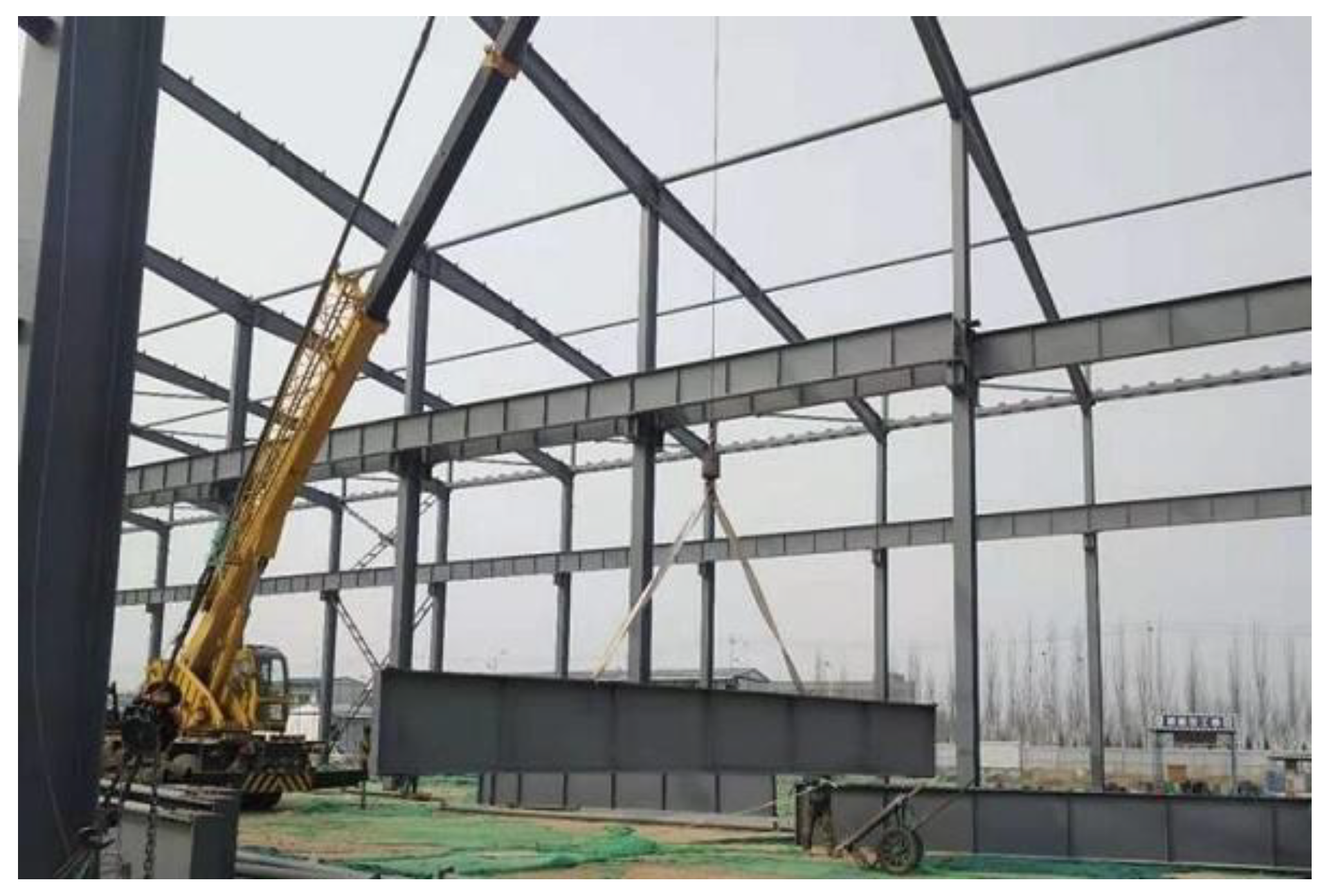
In order to study the influence of track eccentricity on the strength, deflection, and fatigue of steel crane beam, a steel structure workshop was taken as the research object. The longitudinal length of the main steel structure workshop is 291.8 m, and the column distance is 9 m and 12 m. The transverse width of 90 m is divided into 3 spans, with spans of 36 m, 24 m, and 30 m, respectively. The crane settings are shown in Table 1, among which the 30 m span crane beams make up the heavy duty working system, and the rest make up the intermediate working system. The picture of the crane beam is shown in Figure 1.

Table 1.
Crane layout of main workshop.

Figure 1.
Photo of crane beam.
After the workshop was put into operation, abnormal noise appeared in the track during the operation of the crane, and the noise was sizable. At the same time, it was noted that the crane could not move freely. After investigation, it was found that the installation of the crane beam and the crane met the design requirements, but the track on the upper part of the crane beam had a large range of eccentricity. The webs of the 9.0 m and 12.0 m span crane beams are 8 mm, while the maximum installation deviation of the track is 33 mm, far greater than the limit of 4 mm. Actual measurements show that the eccentricity of the track was almost uniformly distributed between 0 and the maximum value. The maximum value of track eccentricity is shown in Table 2:
Table 2.
Maximum eccentricity of the crane beam track (mm).
In the relevant calculation of crane beam, the influence line method is generally used to determine the most unfavorable internal force [21]. Among them, the combination of multiple cranes should be considered when calculating the strength. When calculating the deflection, the load of the largest crane is taken into account [6]. The calculation of the most unfavorable load of the crane beam is shown in Table 3:
Table 3.
Most unfavorable load of crane beam.
It can be seen from Table 2 and Table 3 that the crane beam located in the 30 m span workshop has the largest eccentricity and internal force of the track. Therefore, this paper takes 9 m and 12 m heavy duty crane beams in a 30 m span workshop as the research objects, which cannot only realize the purpose of the study, but also solve additional practical problems.
2.2. Calculation Principle of the Structural Strength of Crane Beam
The force borne by the crane beam is a group of concentrated loads, and the parameters and loads of the crane affect the change in its strength. Therefore, the structural strength of crane beam is firstly analyzed [9]. The strength of the crane beam is analyzed according to the cross sectional geometric characteristics of the crane beam. The normal stress calculation equation for crane beam structural strength is as follows:
where, and , respectively, represent the calculated bending moments of the vertical and transverse horizontal forces of the crane, represents the net sectional modulus of the crane beam to the upper fiber of the x-axis, and represents the net sectional modulus of the flange fiber on the section of the brake beam.
In the operation process of crane beam, its structural strength is also reflected in its web shear stress and local extrusion pressure [22,23]. Therefore, the calculation of web shear stress and local extrusion force is also the key factor affecting the structural strength and deflection of crane beam.
The equation for calculating the shear stress of the web of the crane beam is:
where represents the maximum shear force at the crane beam pillar, represents the height of the web, represents the thickness of the web, and represents the current shear strength value.
The local extrusion pressure of crane beam can be calculated as follows:
where, represents the dynamic coefficient, represents the increased coefficient of the concentrated load, represents the maximum wheel pressure value of the crane, and represents the assumed length of the upper edge of the calculated height of concentrated load on the web.
3. Finite Element Analysis of Crane Beam
According to the basic condition of the crane beam and the principle of the calculation of structural strength analysis, in order to achieve the case of eccentric orbit to analyze the influence of steel crane beam strength and deflection, in this paper, we applied orbital eccentricity to build the finite element model of the crane beam [24,25].
3.1. Finite Element Model of Crane Beam
Midas Gen is a finite element software focusing on structural design, including four categories: building, bridge, rock, and soil simulation. It offers a convenient modeling function, a powerful analysis and design function, and a robust post-processing function. Midas Gen finite element software is used to establish the finite element model of crane beam. The establishment process is as follows:
Step 1: Unit setting. The flange, web, and stiffening ribs of crane beam are simulated with plate elements, and the length of the plate mesh unit is 100 mm
Step 2: Boundary condition setting. The lower flange at both ends of the crane beam is connected to the leg with bolts. One end limits the displacement as , , , and the other end limits the displacement as , , which simulates the hinge bearings of simply supported beams. Both ends of the crane beam upper flange limit displacement are . The upper flange of the 12 m crane beam is provided with a brake plate, and the lower flange is provided with a brake truss, with a support spacing of 2 m. The boundary conditions are set to limit the transverse movement of the crane beam, namely, the limited displacement .
Step 3: Load determination. In addition to the dead weight load, the eccentric load of the crane is loaded in the form of center load and additional bending moment [26]. The additional bending moment is considered in the case of eccentricity of 4 mm, 15 mm, 25 mm, and 35 mm, respectively. The size of the crane beam and the setting of the brake truss are shown in Table 4:
Table 4.
Crane beam size (mm).
The finite element model of the crane beam constructed according to the above steps is shown in Figure 2.
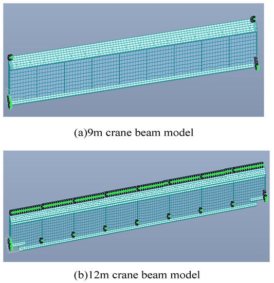
Figure 2.
Midas finite element model of crane beam.
3.2. Finite Element Analysis of Crane Beam
The intensity index (stress), the deformation index (deflection), and the fatigue index of crane beam under different eccentric loadings were analyzed by the finite element model. Among these, in the calculation of strength, it is necessary to consider the role of two cranes, consider the load component coefficient (constant load 1.3, variable load 1.5) and dynamic coefficient (A6 level dynamic coefficient 1.1), and use the load standard value and one crane when calculating deformation and fatigue. The analytical calculation results are shown in Table 5, and the calculation result cloud map is shown in Figure 3.
Table 5.
Finite element calculation results of crane beam.
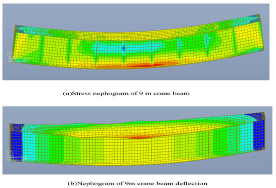
Figure 3.
Construction of finite element model of 9 m crane beam.
The maximum stress of the 12 m span crane beam reaches 35 mm at the upper flange and web (stress is marked in parentheses). Stress and deflection changes in the crane beam at different eccentric track values are shown in Figure 4.

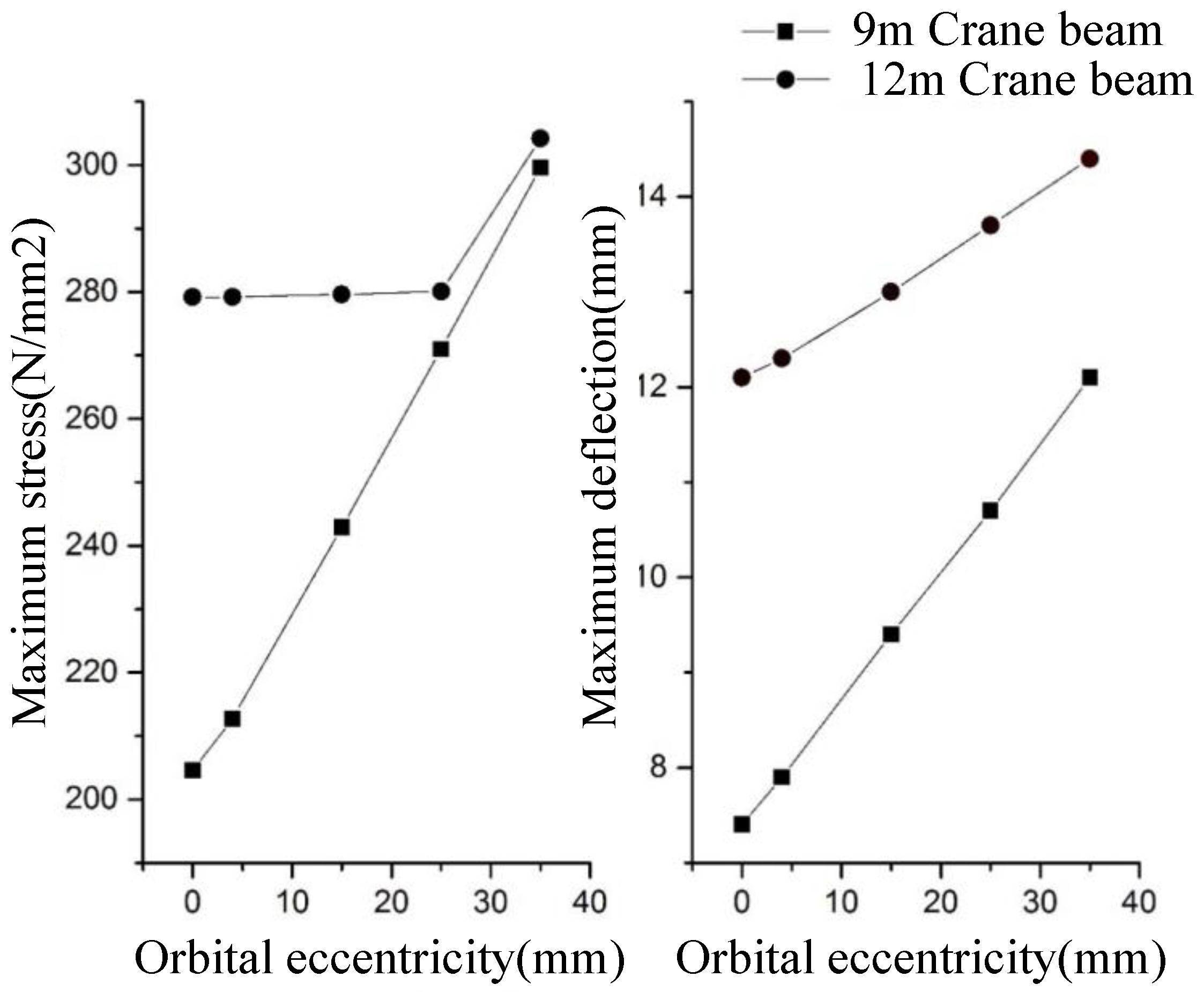
Figure 4.
Stress and deflection of crane beam under eccentric track load.
3.3. Stress and Deflection of Crane Beam under Eccentric Track Load
As can be seen from Figure 4, with the increasing eccentric value of 9 m, the stress of the crane beam increases linearly. When the eccentric value reaches 35 mm, the maximum stress is 299.6 N/mm2, which increases by 46.4% compared with the initial stress of 204.6 N/mm2. The 12 m crane beam is completely different. The stress of the crane beam changes slightly with the eccentric value; but when the eccentric value exceeds 25 mm, the stress value increases suddenly.
The linear relationship between the stress and eccentricity value of 9 m crane beam can be expressed as Equation (4).
where: refers to the maximum stress value of crane beam (N/mm2), and refers to the eccentric value (mm).
The deflections of 9 m crane beam and 12 m crane beam both increase linearly with the increase in track eccentricity, but the increase in amplitude is different. The increase in deflection of 9 m crane beam is significantly greater than that of 12 m crane beam, by about two times. When the track eccentricity value reaches 35 mm, the deflection increases by 4.7 mm and 2.3 mm, respectively.
The linear relationship between the deflection and eccentricity of 9 m and 12 m crane beams in this project can be expressed in Equations (5) and (6), respectively.
where is the maximum deflection of the crane beam (mm), and is the eccentricity value (mm).
3.4. Fatigue Strength of Crane Beam under Eccentric Track Load
Structural Steel Design Standard GB50017-2017 stipulates that the allowable stress amplitude method be adopted for fatigue calculation, and the stress is calculated according to the elastic state.
The calculation equation is:
where: (heavy duty system), stress amplitude, allowable stress amplitude related to the connection form of the component, weld I-steel 144 N/mm2. Figure 5 shows the relationship between the stress amplitude and the allowable stress of 9 m and 12 m crane beams.
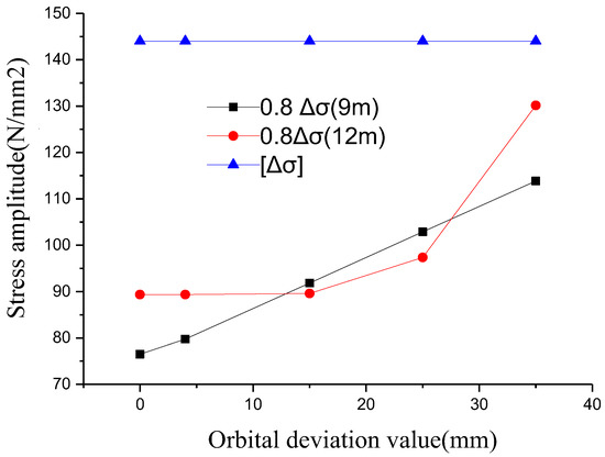
Figure 5.
Maximum stress amplitude of the crane beam under the action of eccentric dynamic load.
Figure 5 shows that the stress amplitude of crane beam under eccentric loading increases with the increase in eccentric value. The stress amplitude of 9 m crane beam has a linear relationship with the eccentricity value, while the stress amplitude of 12 m crane beam scarcely increases when the eccentricity value is less than 15 mm. When the eccentricity value is greater than 15 mm, the stress amplitude, along with the eccentricity value, rapidly increases. In addition, it can be seen from the figure that when the eccentricity value reaches 35 mm, the maximum stress amplitude of the crane is still less than the allowable stress amplitude, and the fatigue calculation meets the design requirements. The cross section of the crane beam is controlled by strength and deflection, rather than fatigue.
3.5. Effect of a Brake Truss on the Stress and Deflection of Crane Beam
When the crane beam is not equipped with a brake truss, the eccentricity of the track will not increase the vertical bending moment of the crane beam, but the crane beam will produce torsional bending moment. The crane beam of this project is beam, which has very small torsional stiffness and large additional stress caused by torsional bending moment. In Figure 4, the part of 9 m crane beam stress increasing with track eccentricity is the additional torsional stress. When track eccentricity is 35 mm, the additional stress reaches 95 N/mm2. As for the 12 m crane beam in Figure 4, when the track eccentricity value is greater than 25 mm, the maximum stress of the crane beam transfers from the middle of the lower flange span to the joint portion of the upper flange and web, and the maximum stress begins to increase with the increase in the eccentricity value.
The deflection of crane beam is different with or without a braking truss under eccentric loading. This is because torsion will occur under the action of eccentric loading, which will cause additional downward displacement on the upper flange of the crane beam. Meanwhile, due to the eccentric action of the track on the upper flange, the upper flange will also produce downward displacement due to local deformation. The deflection increment of 9 m crane beam is the sum of the two, and the deflection increment of 12 m crane beam is only .
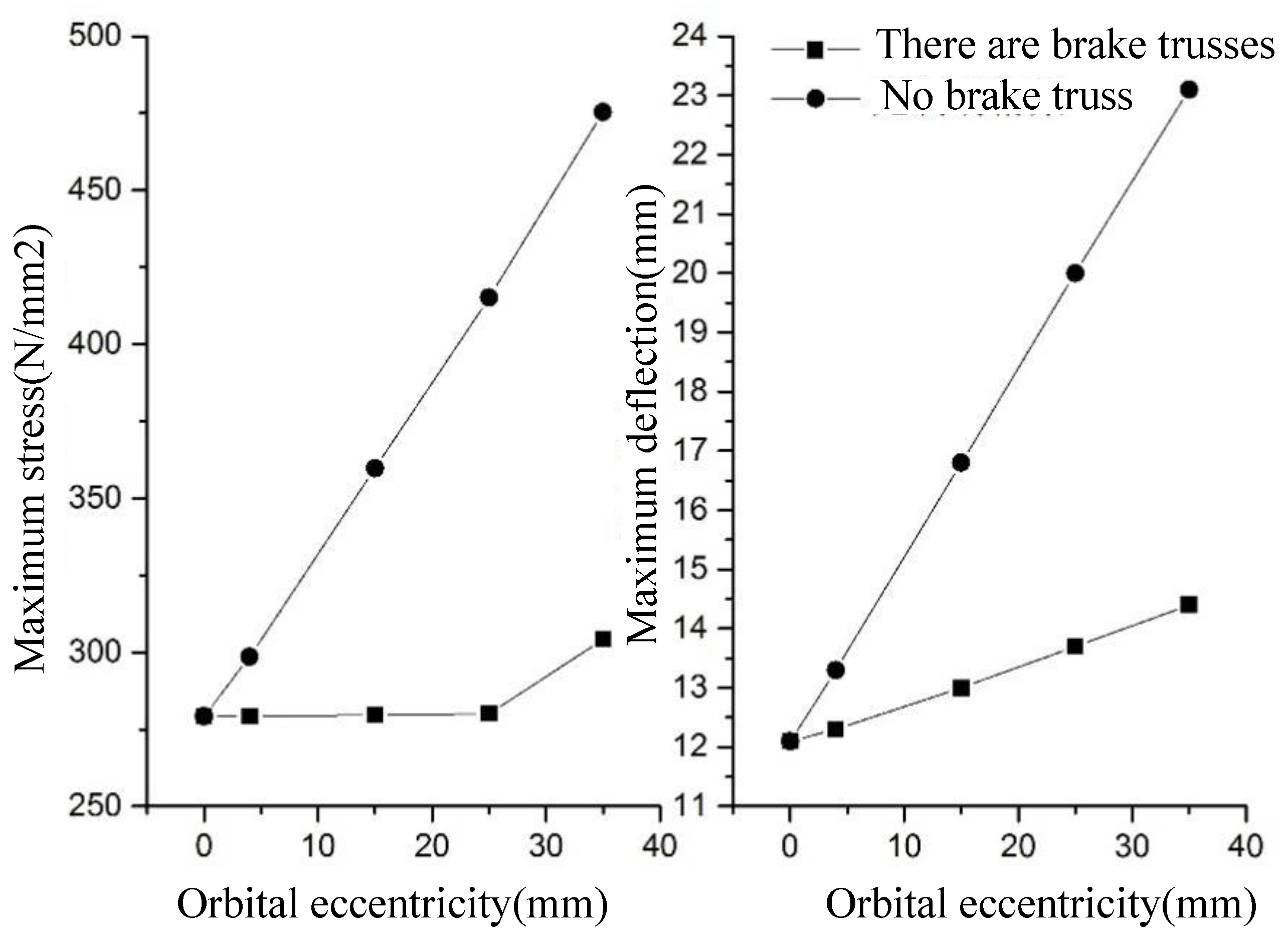
The braking truss of 12 m crane beam was removed from the finite element software, and its stress and deflection under the same working condition were analyzed and compared with the previous analysis results, as shown in Figure 6.
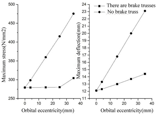
Figure 6.
Stress and deflection of 2 m crane beam under eccentric track loading.
When the eccentricity is 0, the stress and deflection of the crane beam are the same with or without the brake truss. As the orbital eccentricity increases, when there is no brake truss, the stress and deflection of crane beam increase rapidly. However, when the crane beam has a brake truss, its stress scarcely changes, and the increase in deflection obviously decreases.
In summary, the brake truss has a significant effect on the rail eccentricity of the crane beam, which can completely offset the additional stress caused by eccentricity and greatly reduce the additional deflection caused by eccentricity (about 50% reduction). When the eccentricity value exceeds a certain limit, the position of the maximum stress will also shift, and the brake truss will not limit the increase in additional stress.
4. Reinforcement Measures
The stress limit of 9 m crane beam is 305 N/mm2, and the deflection limit is 9.0 mm; the track eccentricity value is 37 mm and 12 mm, respectively. When the track eccentricity value of 9 m crane beam exceeds the deflection and the crane beam exceeds 12 mm, reinforcement measures must be taken. The stress limit of 12 m crane beam is 305 N/mm2, and the deflection limit is 12.0 mm; the stress and deflection (and the eccentricity of the orbit is 0) are 279.2 N/mm2 and 12.1 mm, respectively, which are similar to the limit. Therefore, the 12 m crane beam was used for the project.
The reinforcement measures mainly include: the reinforcement design scheme, as well as the welding process between the reinforcement and the crane beam.
4.1. Reinforcement Design Scheme
According to the above analysis results, due to the influence of torsional stiffness, the stress and deflection of the crane beam increase greatly under the action of biased loading. Therefore, the corresponding reinforcement scheme is designed, and because, as mentioned in the conclusion, the fatigue strength of the crane beam has no controlling effect on it, it is not necessary to consider the increasing fatigue strength when considering the reinforcement scheme.
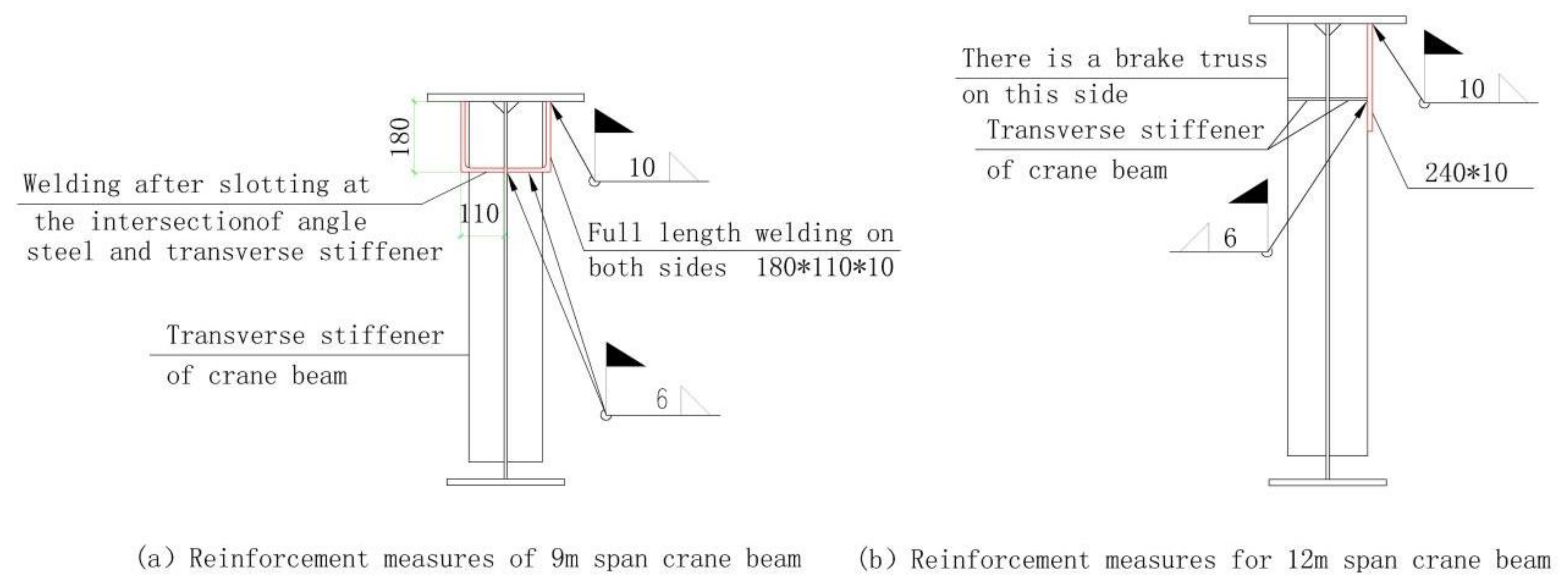
(1) There is no brake truss in 9 m crane beam. Angle steel is welded on both sides of the lower flange to form a box-shaped section on the upper part of the crane beam, which greatly improves the torsional stiffness while increasing the segment of the crane beam. The dimensions of the angle steel used in the reinforcement are determined by trial calculation, and the final reinforcement design scheme is shown in Figure 7a.
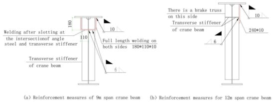
Figure 7.
Reinforcement measures for crane beam.
(2) There are brake trusses and longitudinal stiffening ribs on one side of the 12 m crane beam, so the side without brake trusses is selected for the reinforcement measures of the welding of steel plates, and a box-shaped section is also formed on the upper part of the crane beam to increase the section size and torsional stiffness. The size of the reinforcement steel plate is determined by trial calculation, and the final reinforcement design scheme is shown in Figure 7b.
(3) After reinforcement, the stress and deflection of the crane beam are calculated using the finite element method. As can be seen from the calculation results in Table 6, the maximum stress and deflection of the crane beam both decrease, and the track eccentricity reaches 35 mm, which also meets the specification requirements. The maximum deflection of crane beam track in this project is 33 mm (see Table 2), and the reinforcement measures have obvious effects.
Table 6.
Finite element calculation results for crane beam.
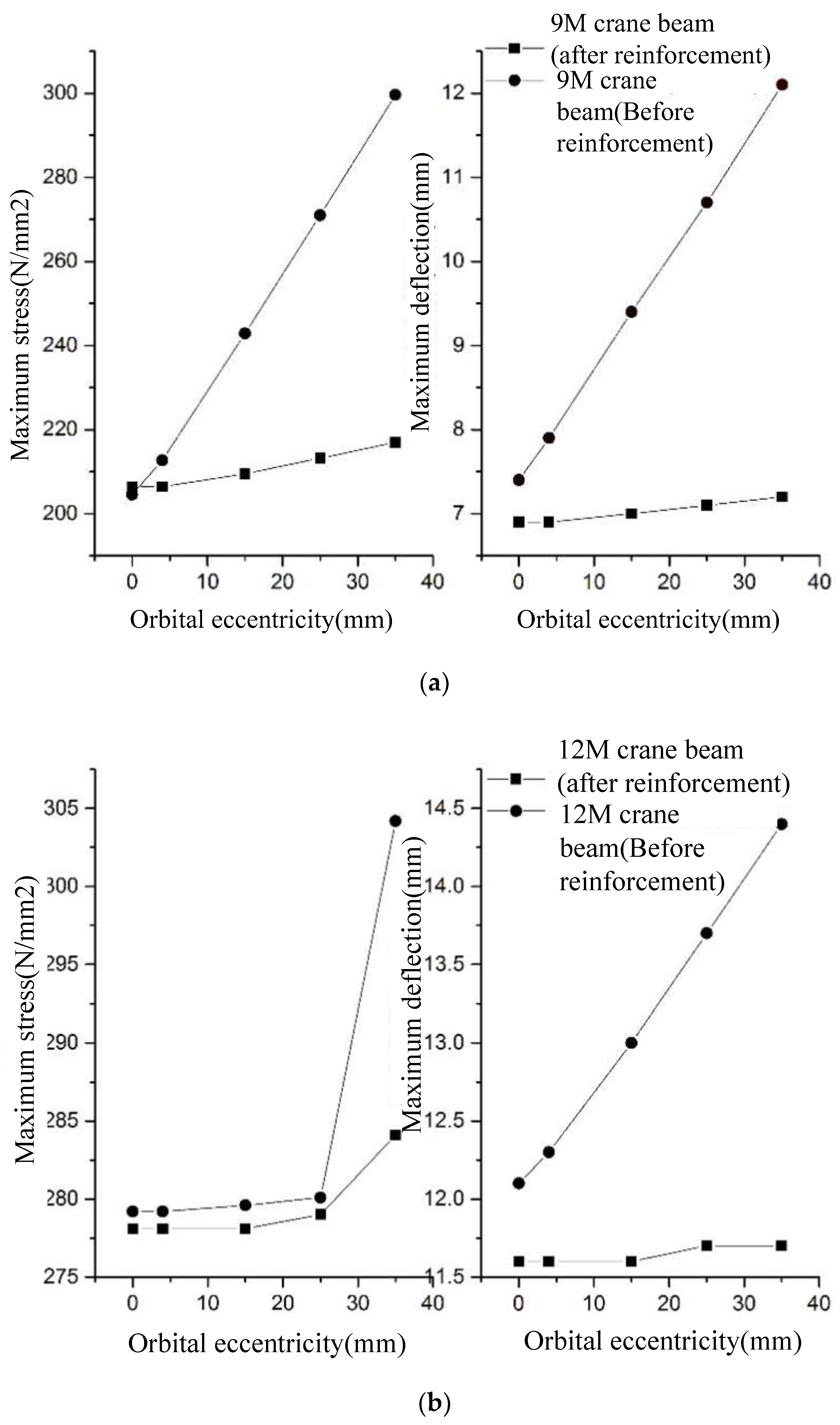
Figure 8 shows the maximum deflection and stress changes in the crane beam before and after the reinforcement. After the reinforcement of 9 m and 12 m crane beam, the stress and deflection not only decreased numerically, but their amplitude also increased (represented by a decrease in the slope of the line). This further shows that the additional stress and deflection due to the torsional moment are the main reasons for the increase in the deflection and stress of the crane beam under eccentric loading, when the track is eccentric. The reinforcement scheme of increasing torsional stiffness of crane beam adopted in this project is effective.

Figure 8.
Maximum stress and deflection of crane beam before and after reinforcement. (a) The maximum stress and deflection of 9 m crane beam before and after reinforcement; (b) the maximum stress and deflection of 12 m crane beam before and after reinforcement.
4.2. Welding Process
In the reinforcement process of this project, the reinforcement parts are connected to the crane beam by welding. The residual stress generated during welding will affect the strength and stiffness of the crane beam, and also produce very sensitive deformation [14]. ABAQUS and ANSYS software can realize the numerical analysis of the residual stress of the weld [27,28,29,30]. Among these, ABAQUS is also a powerful finite element software that can be used for engineering simulation. It can solve both relatively simple linear analysis problems and more complex nonlinear problems. It offers various types of material model libraries and can simulate the properties of various materials in engineering, with outstanding advantages. In the realization of the reinforcement scheme shown in Figure 7, this paper uses ABAQUS software to analyze the reinforcement scheme of the crane beam in this project, and studies whether the material used for the reinforcement parts and the welding seams should use continuous welding or discontinuous welding [31].
4.2.1. Model
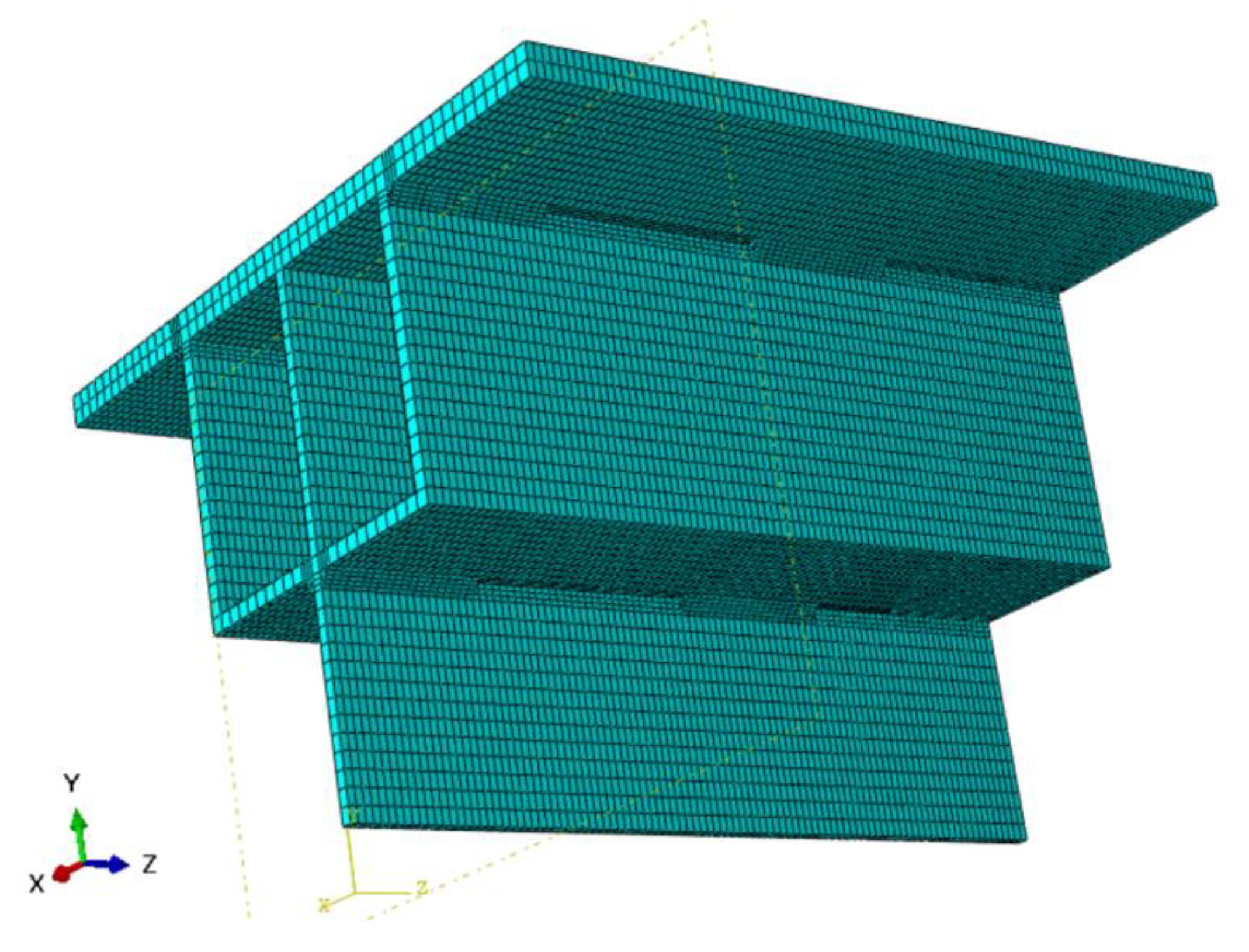
Because the original size of the crane beam is large, the model is further simplified. In the welding process, the parts far away from the weld will be less affected by welding. Therefore, the 0.5 m length of the crane beam is taken as the research object, and the parts 0.35 m below the top of the web are cut out. In this model, the more densely the finite element mesh is divided, the higher the calculation accuracy will be. In this model, the mesh size at the weld is 5 mm, and the mesh size in other areas is 10 mm. The specific mesh division is shown in Figure 9.

Figure 9.
ABAQUS model of crane beam.
4.2.2. Thermophysical and Mechanical Parameters of Materials
The welding temperature field simulation belongs to nonlinear transient thermal analysis. In the welding process, it is assumed that the convective coefficient h = 25 W/(m°C), and some data are determined by linear interpolation. In the simulation, the latent heat of the solid–liquid phase change in the welding process was considered. The liquefaction temperature of the weld element was set to 1500 °C, the curing temperature was set to 1450 °C, the latent heat value was 270 kJ/kg, and the room temperature was 20 °C during welding.
In the process of welding, the temperature changes significantly, so it is necessary to primarily consider the influence of temperature on the material elastic modulus, Poisson’s ratio, the thermal expansion coefficient, and other mechanical property parameters, determining the material thermal conductivity, specific heat capacity, and other thermal physical properties parameters as temperature change.
4.2.3. The Heat Source Model
The ellipsoid heat source model was selected and the heat source movement velocity was defined as 5 mm/s to simulate the welding process. In numerical simulation, a welding voltage of 19.6 V, welding current of 160 A, welding speed of 5 mm/s and welding thermal efficiency of 80% were defined.
The heat source model includes a front semi-ellipsoid and a back semi-ellipsoid, whose corresponding heat flux distribution functions are:
where, and are the heat source density in the model, ; and are anterior and posterior semicircular ellipsoid distribution functions, respectively. is the instantaneous input heat of the heat source heating component, ; and are the shape parameters of the heat source model; , , are the welding starting point coordinates; and is the moving distance of the welding heat source.
4.2.4. The Results of the Analysis
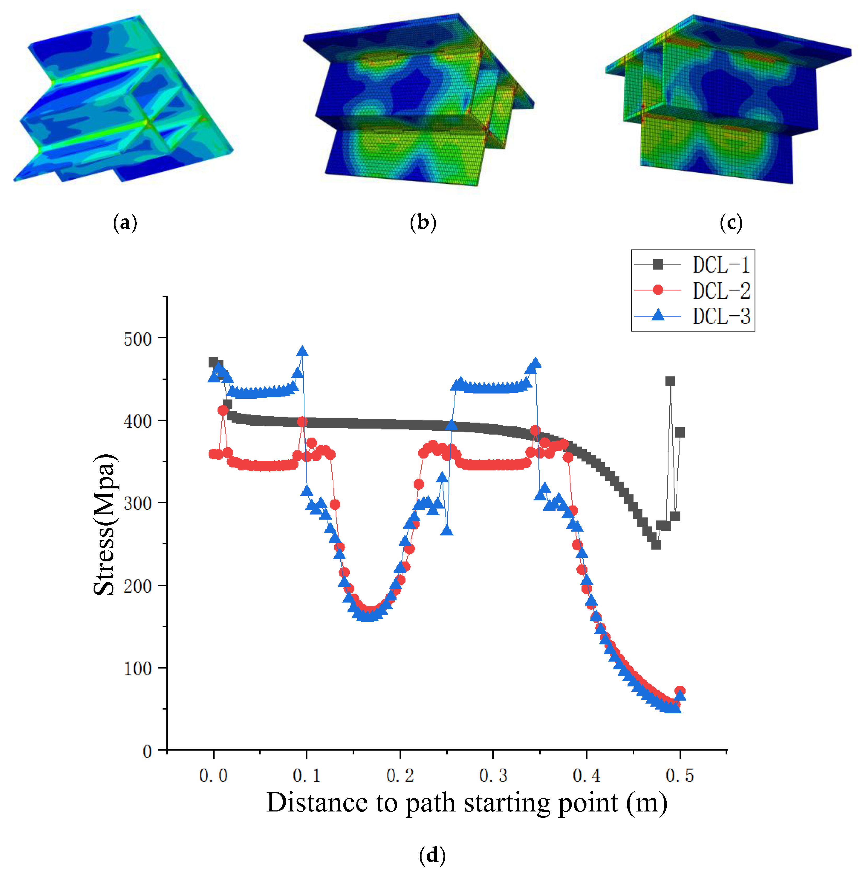
The material of the crane beam in this project is Q345B. Because the reinforced parts mainly play the role of increasing torsional stiffness, the material of the reinforced parts can be either Q235B or Q345B. The welds can be completed using intermittent welding or continuous welding. The project requires the intermittent welding seam length of 100 mm, and a 150 mm interval. The aforementioned model, parameters, reinforcement material, and weld form are used to conduct the numerical simulation of the residual stress of the welding seam of crane beam, and the analysis results are shown in Table 7. According to the analysis results, the distribution curve of residual stress is drawn, as shown in Figure 9.
Table 7.
Residual stress analysis results of the crane beam weld.
The analysis results show that the average value of residual stress is 22% less than that of continuous welding; the average residual stress decreases by 7%, and the maximum residual stress decreases by 17% when the reinforced parts are made of the same material as the crane beam. Therefore, when implementing the reinforcement scheme shown in Figure 10, the reinforcement parts are made of Q345 material and welded by intermittent welding. At the same time, when the intermittent welding is used in the actual welding, the deformation in the welding process is reduced by using symmetric jump welding from both ends of the crane beam.

Figure 10.
Residual stress distribution of the welding seam of the crane beam reinforcement scheme; the distribution of (a–c) is the cloud diagram of the residual stress distribution of DCL-1, DCL-2, and DCL-3. (d) The residual stress distribution curve of the welding seam of the crane beam.
5. Conclusions
In this paper, Midas Gen finite element software is used to establish the finite element model of the crane beam; to determine the stress, deflection, and stress amplitude of the crane beam under the action of eccentric track loading; and to complete the analysis of the influence of track eccentricity on the strength deflection fatigue of the steel crane beam. The results show that when there is no brake truss, the maximum stress and deflection of the crane beam will increase significantly under the action of eccentric loading. When the crane beam has a brake truss, it can effectively reduce the adverse effect of eccentric loading on the crane beam. The fatigue calculation of the crane beam under eccentric loading still meets the requirements, and the fatigue strength has no controlling effect. The reason why steel crane beam is sensitive to track eccentricity is that its torsional stiffness is too small. All of the above show that the finite element analysis of crane steel beam under eccentric rail loading is effective, and the proposed reinforcement measures have practical applications, which can provide a certain reference for the reinforcement process of crane steel beam. In the practical application process, when the stress and deflection of the crane beam exceed the limit of the specifications due to the track deviation, the section can be strengthened by welding angle steel or steel plate onto the upper part of the crane beam to form a box section. However, the method in this paper can only be applied to the effective finite element analysis of H-beam crane beams, and the finite element analysis, and the reinforcement measures for other types of crane beams require further consideration in future research. In addition, as the study of this paper is a specific case, buckling or nonlinear analysis is not fully taken into account; therefore, these aspects will be further improved in the subsequent research.
Author Contributions
C.L. proposed the research topic selection, investigated and sorted the literature, and obtained research funds; Z.Y. designed the research program, investigated and collated the literature, and conducted the statistical analysis; P.L. implemented the research process, designed the framework of the paper, and preformed the statistical analysis; X.Z. collected and organized the data, drafted the paper, and provided technical and material support; J.H. implemented the research process, revised the paper, and provided relevant suggestions; L.W. designed the research proposal, performed the final review of the paper, and extracted and discussed the conclusions. All authors have read and agreed to the published version of the manuscript.
Funding
This research received no external funding.
Institutional Review Board Statement
This article does not contain any studies with human participants performed by any of the authors.
Informed Consent Statement
Not applicable.
Data Availability Statement
All data generated or analysed during this study are included in this published article.
Conflicts of Interest
The authors declare no conflict of interest.
References
- Wen, Y.; Yu, J.; Wang, P.X. Study on behavior parameters of steel crane beam under moving loads. Build. Struct. 2020, 13, 89–94. [Google Scholar]
- Yang, Y.F.; Wu, J.; Yue, Q.X. Research on Fatigue Performance and Reinforcement of Upper Section of Steel Crane Beam. Steel Constr. 2018, 11, 107–112,126. [Google Scholar]
- Ministry of Housing and Urban-Rural Development. Acceptance Standard for Construction Quality of Steel Structure Engineering: Gb50205-2020; China Planning Press: Beijing, China, 2020.
- Zhou, X.; Bai, Y.; Nardi, D.C.; Wang, Y.; Wang, Y.; Liu, Z.; Flórez-López, J. Damage evolution modeling for steel structures subjected to combined high cycle fatigue and high-intensity dynamic loadings. Int. J. Struct. Stab. Dyn. 2022, 22, 2240012. [Google Scholar] [CrossRef]
- Yang, Y.F.; Chen, Q.; Lei, M. Fatigue reliability analysis of a steel crane beam in service. J. Vib. Shock 2020, 9, 165–172, 193. [Google Scholar]
- Zheng, L.C.; Hu, Y.H.; Yao, B.; Wang, J.Y.; Li, J.G. Analysis of mechanical properties and strengthening measures of steel crane girders with rail eccentricity. Steel Constr. 2018, 5, 102–106, 121. [Google Scholar]
- Zhao, X.Q.; Yue, Q.R.; Xing, K.T. Research on fatigue properties of plug-plat end of crane runway girders variable section abutment with right angle end-plate. J. Build. Struct. 2020, 08, 116–123. [Google Scholar]
- Tong, S.G. Rational design of crane runway girders. Steel Constr. 2020, 03, 65–73. [Google Scholar]
- Xu, Z.G.; Guo, X.; Deng, C.G. Finite element analysis on fatigue life of a corrugated web H-shaped steel crane beam. Prog. Steel Build. Struct. 2021, 2, 88–97. [Google Scholar]
- Liu, W.; Liu, L.; Wu, H.; Chen, Y.; Zheng, X.; Li, N.; Zhang, Z. Performance analysis and offshore applications of the diffuser augmented tidal turbines. Ships Offshore Struct. 2022, 1–10. [Google Scholar] [CrossRef]
- Ao, S.K. Design and finite element analysis of variable section steel crane beam with right angle mutation bearing. China Constr. Met. Struct. 2021, 9, 83–85. [Google Scholar]
- Gong, Y.F.; Jia, F. Based on nCode design-life in fatigue reliability analysis of a steel structure crane beam. J. Liaoning Tech. Univ. 2018, 2, 371–375. [Google Scholar]
- Zhang, H.; Liu, Y.; Deng, Y. Temperature gradient modeling of a steel box-girder suspension bridge using Copulas probabilistic method and field monitoring. Adv. Struct. Eng. 2021, 24, 947–961. [Google Scholar] [CrossRef]
- Han, T.F.; Li, X.D.; Xi, X.D.; Qiu, J.K.; Xu, G.; Chen, D. Analysis of vibration and cracking of steel crane beam in heavy-duty plant. Steel Constr. 2018, 6, 61–65. [Google Scholar]
- Tao, L.; Deng, H.C.; Xu, G.T.; Li, Q.P. Study on mechanical properties of reinforce steel crane beam without brake structures base don ANSYS. Build. Struct. 2021, 4, 33–38. [Google Scholar]
- Wang, L.; Zheng, W.C.; Hu, Z.H.; Luo, F.S.; Fu, Z.J.; Liu, L. Fatigue performance analysis of abrupt change of right angle abrupt steel crane girder with heavy duty system. Steel Constr. 2018, 10, 89–91. [Google Scholar]
- Huang, H.; Huang, M.; Zhang, W.; Yang, S. Experimental study of predamaged columns strengthened by HPFL and BSP under combined load cases. Struct. Infrastruct. Eng. 2021, 17, 1210–1227. [Google Scholar] [CrossRef]
- Zhang, Y.T. Finite element analysis of fatigue fracture process of crane beam. Fujian Qual. Manag. 2019, 6, 142. [Google Scholar]
- Liu, C.; Zhao, Y.; Wang, Y.; Zhang, T.; Jia, H. Hybrid dynamic modeling and analysis of high-speed thin-rimmed gears. J. Mech. Des. 2021, 143, 123401. [Google Scholar] [CrossRef]
- Zhang, L.; Zhang, H.; Cai, G. Themulti-class fault diagnosis of wind turbine bearing based on multi-source signal fusion and deep learning generative model. IEEE Trans. Instrum. Meas. 2022, 71, 3514212. [Google Scholar]
- Zhao, X.; Sun, J.W.; Li, Y. Three-web right angle mutant support steel crane beam mechanical performance analysis. Struct. Eng. 2021, 4, 174–180. [Google Scholar]
- Lu, Z.H. Application of carbon fiber in reinforcement of steel crane beam in heavy work shop. Shanghai Constr. Sci. Technol. 2020, 2, 5–9. [Google Scholar]
- Mousavi, A.A.; Zhang, C.; Masri, S.F.; Gholipour, G. Structural damage detection method based on the complete ensemble empirical mode decomposition with adaptive noise: A model steel truss bridge case study. Struct. Health Monit. 2022, 21, 887–912. [Google Scholar] [CrossRef]
- Yang, Y.F.; Ren, H.L.; Ling, H. Analysis and prediction of fatigue life of steel crane runway girder. Steel Constr. 2019, 6, 36–43. [Google Scholar]
- Wei, J.; Xie, Z.; Zhang, W.; Luo, X.; Yang, Y.; Chen, B. Experimental study on circular steel tube-confined reinforced UHPC columns under axial loading. Eng. Struct. 2021, 230, 111599. [Google Scholar] [CrossRef]
- Zhao, X.Q.; Yue, Q.R.; Guo, X.H.; Bi, D.S.; Xing, K.T.; Yang, J.P.; Yan, Y.; Liu, X.G. Study on under load effect equivalent coefficient method for fatigue evaluation of steel crane beams. J. Build. Struct. 2021, 1, 179–188. [Google Scholar]
- She, C.L.; Su, K.L.; Zhang, C.X.; Tan, L.H. Finite element numerical simulation of temperature field and stress-strain field in steel plate welding. Weld. Technol. 2021, 4, 16–20. [Google Scholar]
- Bai, Y.; Nardi, D.C.; Zhou, X.; Picón, R.A.; Flórez-López, J. A new comprehensive model of damage for flexural subassemblies prone to fatigue. Comput. Struct. 2021, 256, 106639. [Google Scholar] [CrossRef]
- Fan, D.L. Cracking Analysis and reinforcement measures of steel crane beam end support. Shanxi Archit. 2018, 12, 47–48. [Google Scholar]
- Wu, T.G. Research on Cracking Analysis and reinforcement Treatment of steel crane beam in steel mill. China Ventur. Cap. 2020, 25, 149, 152. [Google Scholar]
- Zhang, W.; Liu, X.; Huang, Y.; Tong, M.N. Reliability-based analysis of the flexural strength of concrete beams reinforced with hybrid BFRP and steel rebars. Arch. Civ. Mech. Eng. 2022, 22, 171. [Google Scholar] [CrossRef]


Publisher’s Note: MDPI stays neutral with regard to jurisdictional claims in published maps and institutional affiliations. |
© 2022 by the authors. Licensee MDPI, Basel, Switzerland. This article is an open access article distributed under the terms and conditions of the Creative Commons Attribution (CC BY) license (https://creativecommons.org/licenses/by/4.0/).