
Effect of Machining Trajectory on Grinding Force of Complex-Shaped Stone by Robotic Manipulator


Abstract
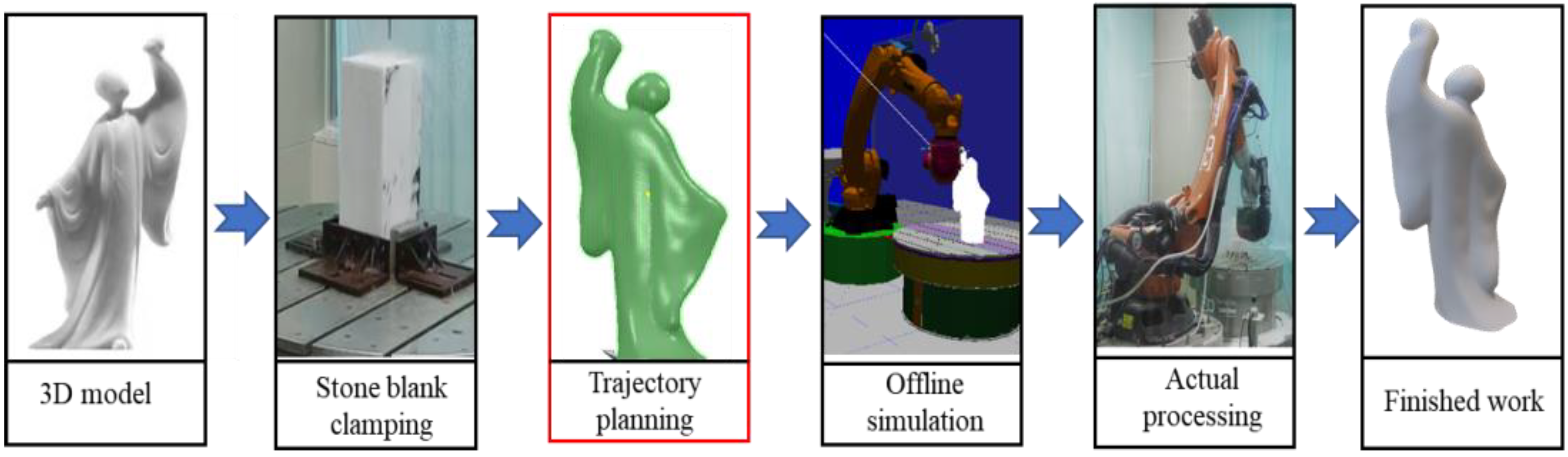
:1. Introduction
2. Finishing Machining Trajectory under the Suppression of Grinding Force Fluctuation
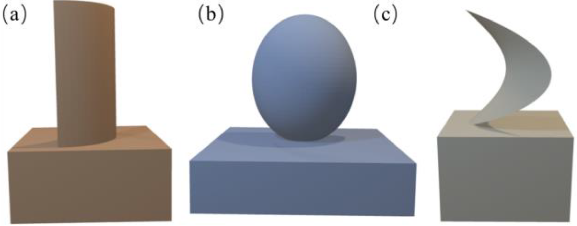
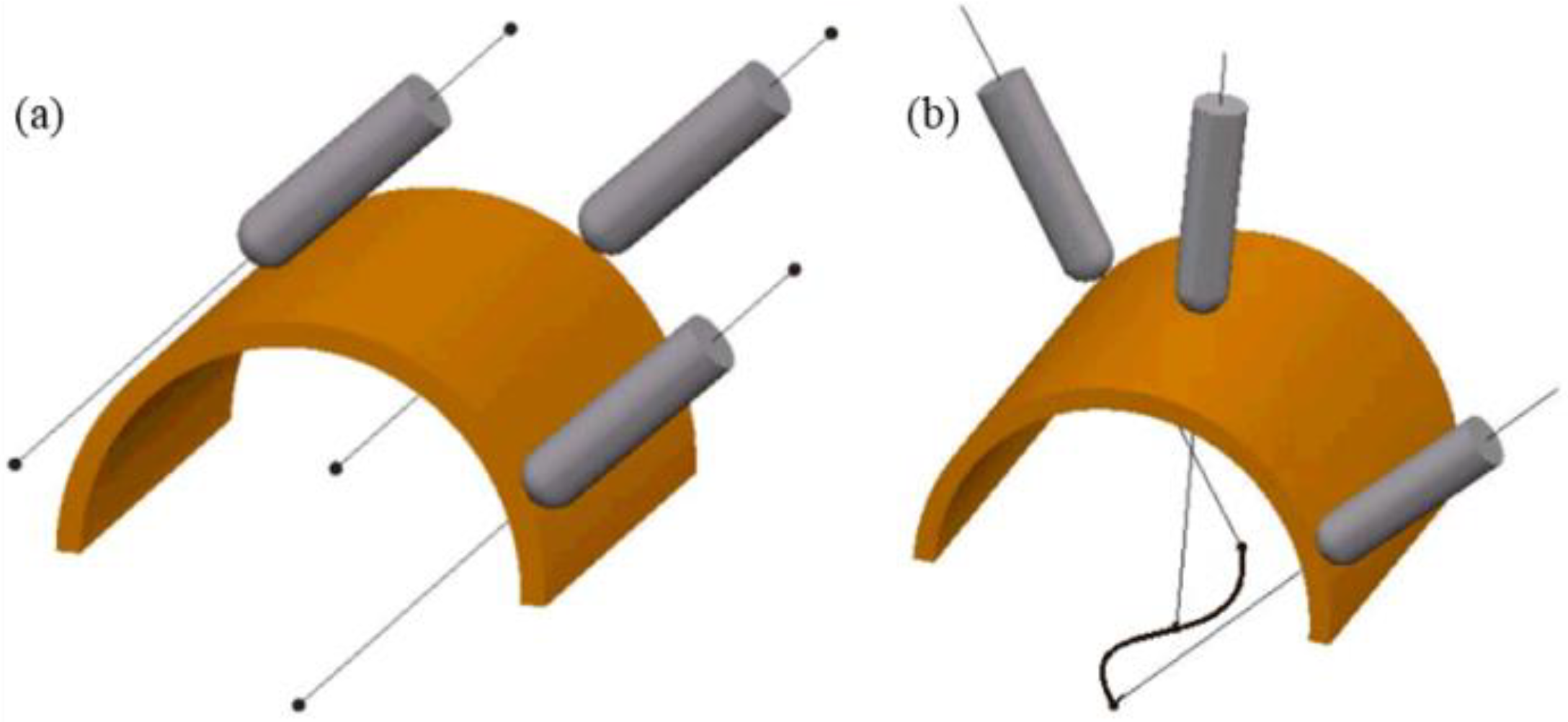
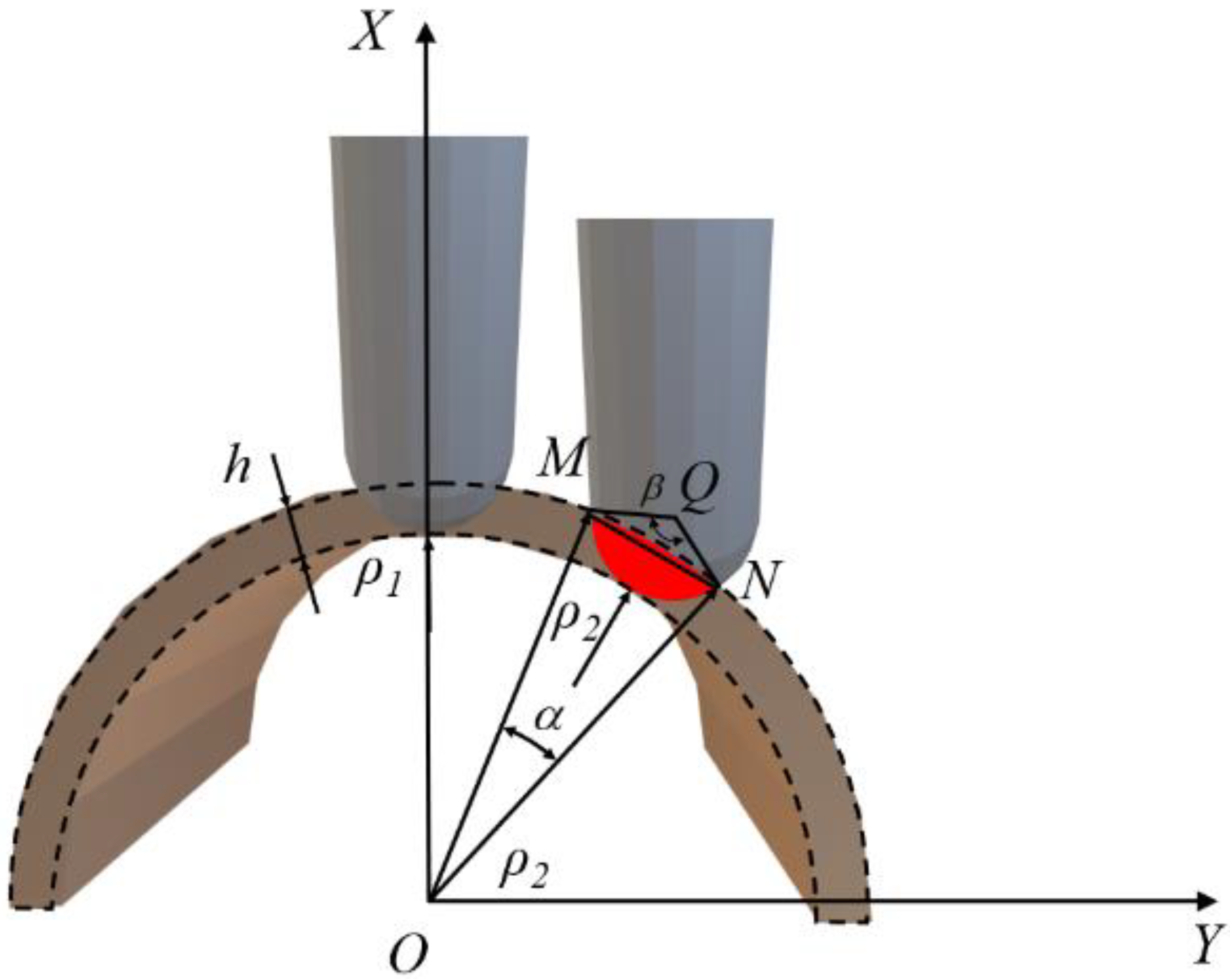
2.1. Generating Principle of Common Tool Path under the Complex Surface
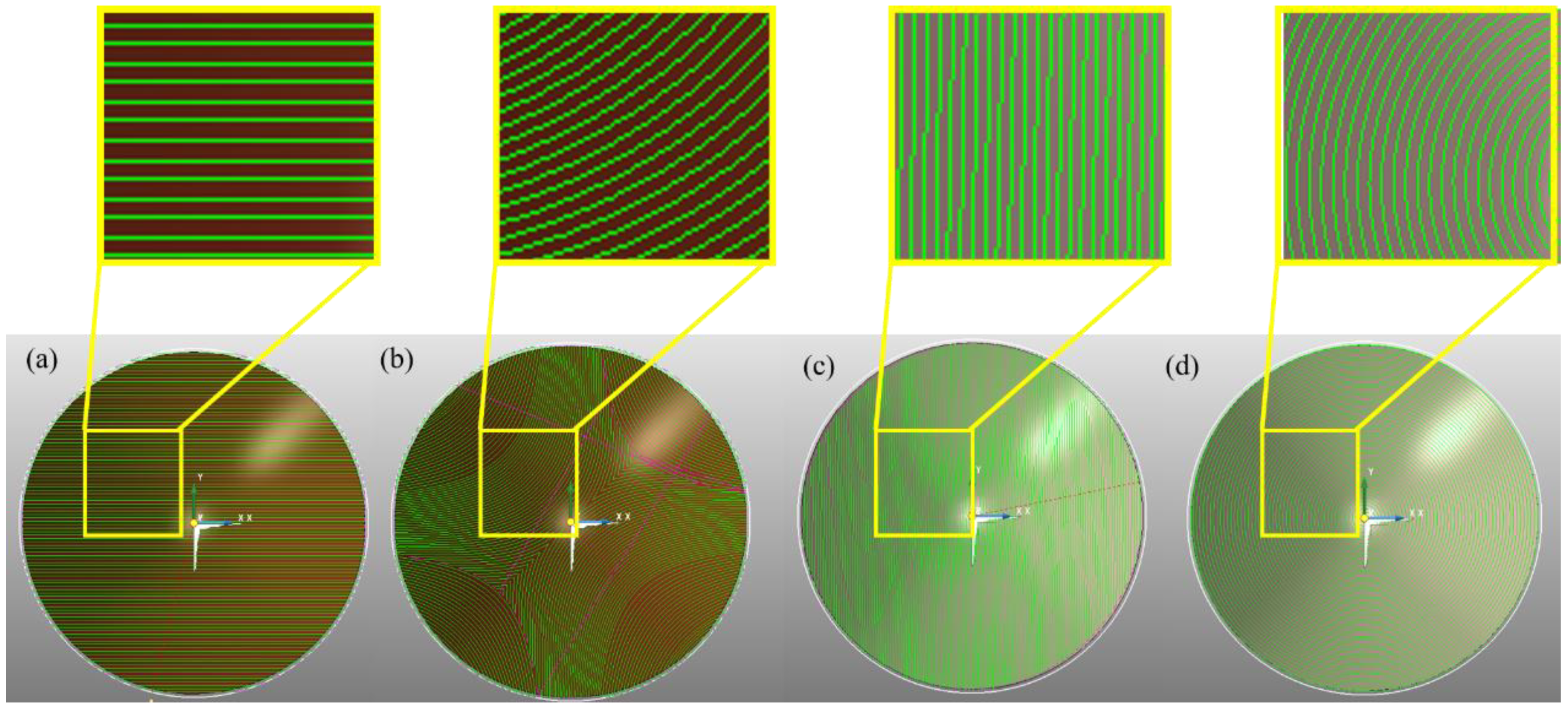
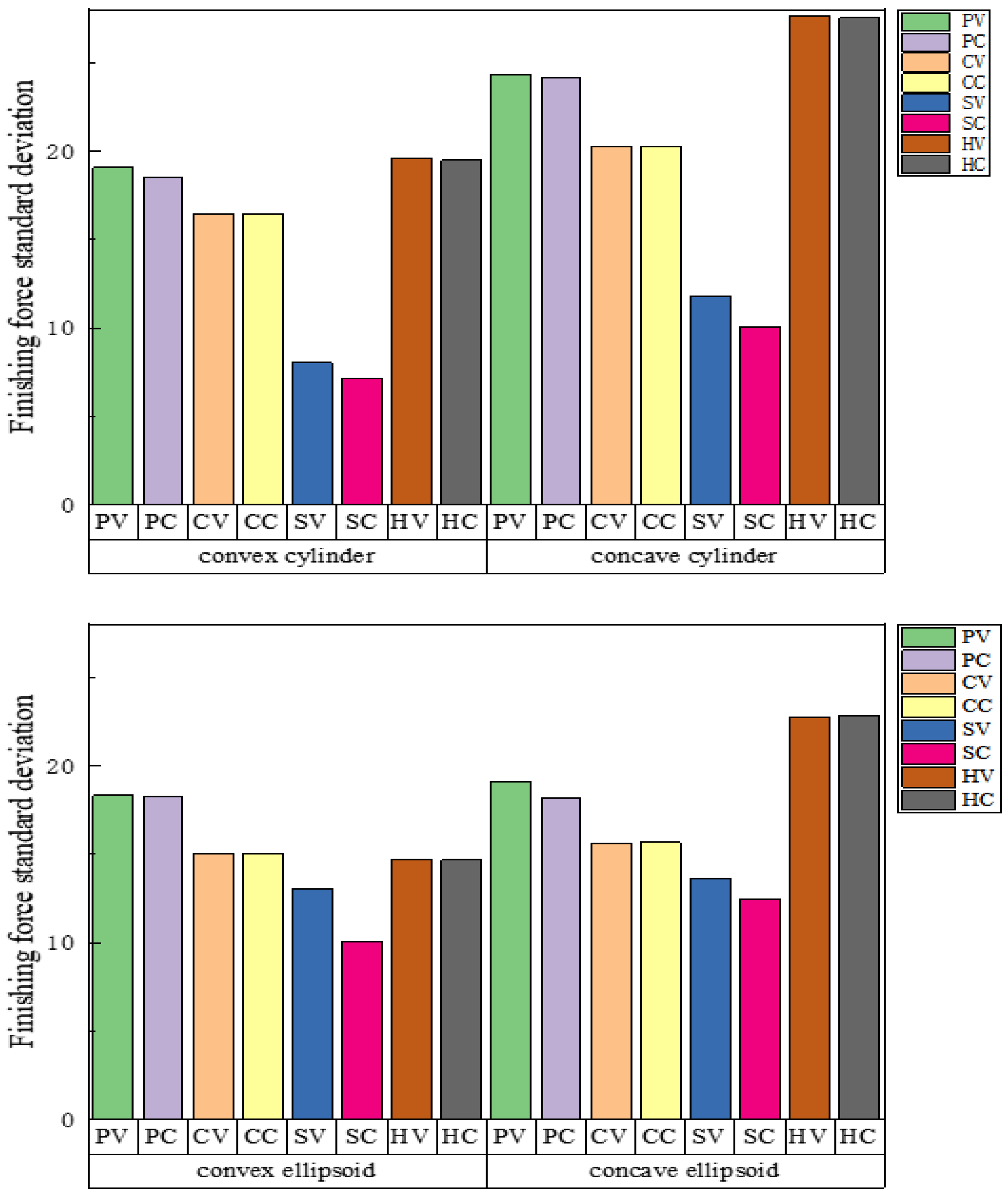
2.2. Simulation of Grinding Force Fluctuation under Different Tool Paths
3. Experimental Validation
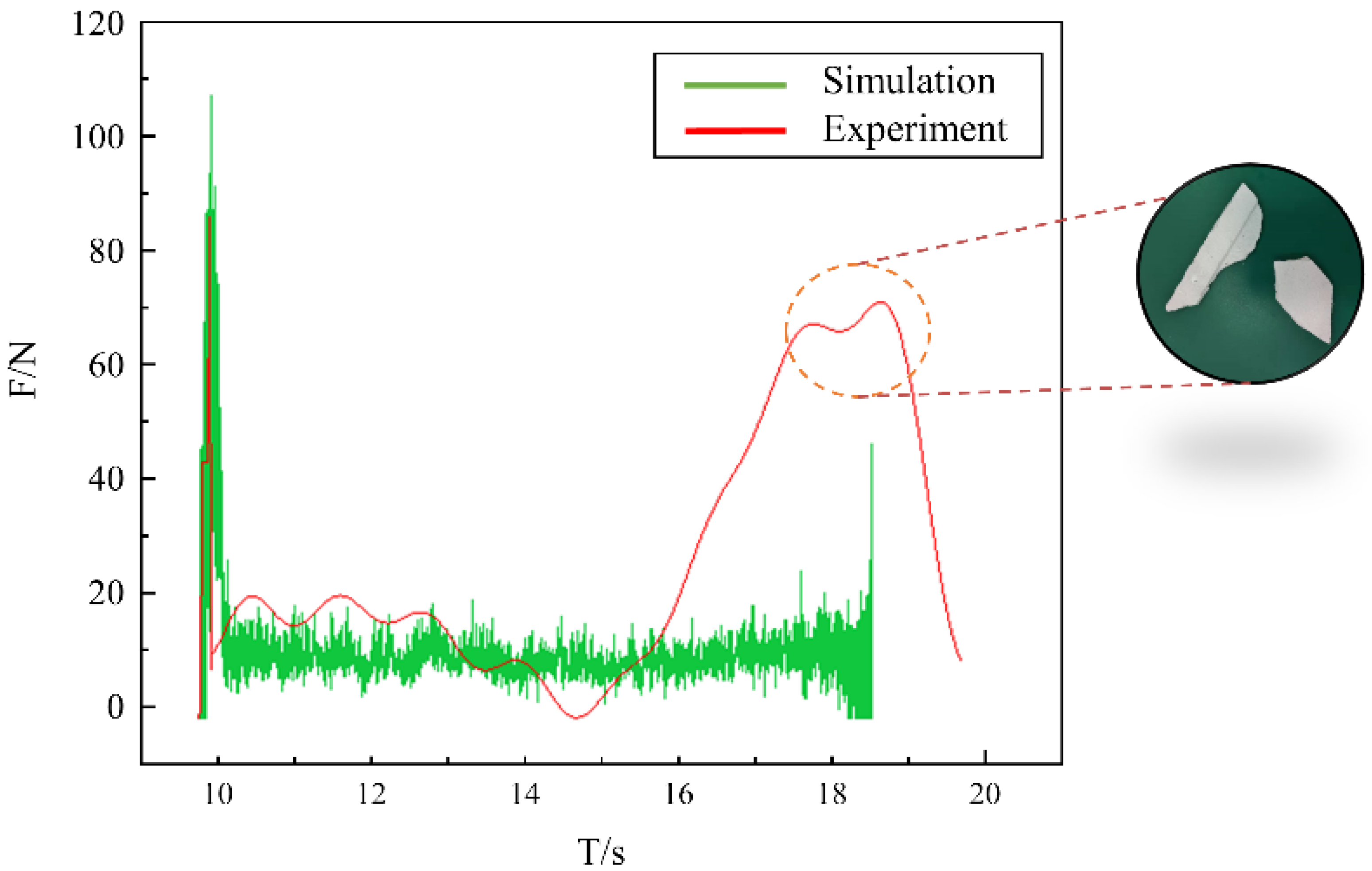
Simulation Reliability Experiment with the Convex Cylinder as an Example
4. Conclusions
- (1)
- The matching relationship between the standard surface characteristics and the tool path is analyzed. The machining conditions of different tool paths were simulated under the standard surface, and it was found that the grinding force fluctuation of the surface-finishing path was the smallest under all surfaces. The optimization effect was the most obvious when machining the concave cylindrical surface, and the fluctuation was reduced by 63.7%. The saddle surface optimization effect produced the worst result at 31.9%.
- (2)
- The method described in this study is verified by CSSP. First, experiments were conducted on the convex cylindrical surface to verify the reliability of the simulation data in this study. The experiment shows that changing the trajectory can reduce the fluctuation of the cylindrical grinding force by 52.8%, and the surface profile error can be reduced by 36.9%.
Author Contributions
Funding
Informed Consent Statement
Data Availability Statement
Conflicts of Interest
References
- Kilicaslan, S.; Ozgoren, M.; Ider, S. Hybrid Force and Motion Control of a Three-Dimensional Flexible Robot Considering Measurement Noises. Machines 2022, 10, 513. [Google Scholar] [CrossRef]
- Lamikiz, A.; de Lacalle, L.N.L.; Sánchez, J.A.; Salgado, M.A. Cutting Force Estimation in Sculptured Surface Milling. Int. J. Mach. Tools Manuf. 2004, 44, 1511–1526. [Google Scholar] [CrossRef]
- Yin, F.C.; Ji, Q.Z.; Wang, C.Z. Research on Machining Error Prediction and Compensation Technology for a Stone-Carving Robotic Manipulator. Int. J. Adv. Manuf. Technol. 2021, 115, 1683–1700. [Google Scholar] [CrossRef]
- Huang, Z.; Song, R.; Wan, C.; Wei, P.; Wang, H. Trajectory Planning of Abrasive Belt Grinding for Aero-Engine Blade Profile. Int. J. Adv. Manuf. Technol. 2019, 102, 605–614. [Google Scholar] [CrossRef]
- Lu, L.; Zhang, J.; Fuh, J.Y.H.; Han, J.; Wang, H. Time-Optimal Tool Motion Planning with Tool-Tip Kinematic Constraints for Robotic Machining of Sculptured Surfaces. Robot. Comput. Integr. Manuf. 2020, 65, 101969. [Google Scholar] [CrossRef]
- Stejskal, M.; Vavruska, P.; Zeman, P.; Lomicka, J. Optimization of Tool Axis Orientations in Multi-Axis Toolpaths to Increase Surface Quality and Productivity. In Proceedings of the Procedia CIRP; Elsevier B.V.: Amsterdam, The Netherlands, 2020; Volume 101, pp. 69–72. [Google Scholar]
- Yan, C.; Lee, C.H.; Li, X.; Zhang, Y.; Min, K. A Multi-Objective Tool-Axis Optimization Algorithm Based on Covariant Field Functional. J. Manuf. Syst. 2018, 48, 30–37. [Google Scholar] [CrossRef]
- Guo, Q.; Zhao, B.; Jiang, Y.; Zhao, W. Cutting Force Modeling for Non-Uniform Helix Tools Based on Compensated Chip Thickness in Five-Axis Flank Milling Process. Precis. Eng. 2018, 51, 659–681. [Google Scholar] [CrossRef]
- Amersdorfer, M.; Kappey, J.; Meurer, T. Real-Time Freeform Surface and Path Tracking for Force Controlled Robotic Tooling Applications. Robot. Comput. Integr. Manuf. 2020, 65, 101955. [Google Scholar] [CrossRef]
- Chen, Y.L.; Cai, Y.; Tohyama, K.; Shimizu, Y.; Ito, S.; Gao, W. Auto-Tracking Single Point Diamond Cutting on Non-Planar Brittle Material Substrates by a High-Rigidity Force Controlled Fast Tool Servo. Precis. Eng. 2017, 49, 253–261. [Google Scholar] [CrossRef]
- Xu, X.; Chen, W.; Zhu, D.; Yan, S.; Ding, H. Hybrid Active/Passive Force Control Strategy for Grinding Marks Suppression and Profile Accuracy Enhancement in Robotic Belt Grinding of Turbine Blade. Robot. Comput. Integr. Manuf. 2021, 67, 102047. [Google Scholar] [CrossRef]
- Hendriko, H.; Kiswanto, G.; Istiyanto, J.; Duc, E. Implementation of Analytical Boundary Simulation Method for Cutting Force Prediction Model in Five-Axis Milling. Mach. Sci. Technol. 2018, 22, 163–179. [Google Scholar] [CrossRef]
- Ma, J.W.; Song, D.N.; Jia, Z.Y.; Hu, G.Q.; Su, W.W.; Si, L.K. Tool-Path Planning with Constraint of Cutting Force Fluctuation for Curved Surface Machining. Precis. Eng. 2018, 51, 614–624. [Google Scholar] [CrossRef]
- Moodleah, S.; Makhanov, S.S. 5-Axis Machining Using a Curvilinear Tool Path Aligned with the Direction of the Maximum Removal Rate. Int. J. Adv. Manuf. Technol. 2015, 80, 65–90. [Google Scholar] [CrossRef]
- Xu, K.; Tang, K. Five-Axis Tool Path and Feed Rate Optimization Based on the Cutting Force–Area Quotient Potential Field. Int. J. Adv. Manuf. Technol. 2014, 75, 1661–1679. [Google Scholar] [CrossRef]
- Tunc, L.T.; Budak, E.; Bilgen, S.; Zatarain, M. Process Simulation Integrated Tool Axis Selection for 5-Axis Tool Path Generation. CIRP Ann. Manuf. Technol. 2016, 65, 381–384. [Google Scholar] [CrossRef]
- van Tuong, N.; Pokorný, P. A Practical Approach for Partitioning Free-Form Surfaces. Int. J. Comput. Integr. Manuf. 2010, 23, 992–1001. [Google Scholar] [CrossRef]
- Kim, T. Constant Cusp Height Tool Paths as Geodesic Parallels on an Abstract Riemannian Manifold. CAD Comput. Aided Des. 2007, 39, 477–489. [Google Scholar] [CrossRef]
- Zhang, X.; Wang, J.; Yamazaki, K.; Mori, M. A Surface Based Approach to Recognition of Geometric Features for Quality Freeform Surface Machining. CAD Comput. Aided Des. 2004, 36, 735–744. [Google Scholar] [CrossRef]
- Bey, M.; Azouaoui, K.; Boutassouna, M. Sculptured Surfaces Subdivision from 3D Cloud of Points and Association of Optimum Ball Cutters. In Proceedings of the Procedia CIRP; Elsevier B.V.: Amsterdam, The Netherlands, 2018; Volume 77, pp. 582–585. [Google Scholar]
- Liao, Z.Y.; Li, J.R.; Xie, H.L.; Wang, Q.H.; Zhou, X.F. Region-Based Toolpath Generation for Robotic Milling of Freeform Surfaces with Stiffness Optimization. Robot. Comput. Integr. Manuf. 2020, 64, 101953. [Google Scholar] [CrossRef]
- Kumazawa, G.H.; Feng, H.Y.; Barakchi Fard, M.J. Preferred Feed Direction Field: A New Tool Path Generation Method for Efficient Sculptured Surface Machining. CAD Comput. Aided Des. 2015, 67–68, 1–12. [Google Scholar] [CrossRef]
- Hongyao, S.; Yangfan, S.; Linchu, Z.; Jianzhong, F. A Parameter Zone Subdivision Method for Rotary Axes Motion Optimization in Five-Axis Toolpath Generation Using Inverse Evaluation Mechanism. Int. J. Adv. Manuf. Technol. 2018, 98, 3115–3131. [Google Scholar] [CrossRef]
- Cui, Z.; Meng, F.; Liang, Y.; Zhang, C.; Wang, Z.; Qu, S.; Yu, T.; Zhao, J. Sub-Regional Polishing and Machining Trajectory Selection of Complex Surface Based on K9 Optical Glass. J. Mater. Process. Technol. 2022, 304, 117563. [Google Scholar] [CrossRef]
- Shaked, T.; Bar-Sinai, K.L.; Sprecher, A. Adaptive Robotic Stone Carving: Method, Tools, and Experiments. Autom. Constr. 2021, 129, 103809. [Google Scholar] [CrossRef]
- Liu, W.; Zhu, X.; Jing, J. The Analysis of Ductile-Brittle Failure Mode Transition in Rock Cutting. J. Pet. Sci. Eng. 2018, 163, 311–319. [Google Scholar] [CrossRef]
- Dai, X.; Huang, Z.; Shi, H.; Wu, X.; Xiong, C. Cutting Force as an Index to Identify the Ductile-Brittle Failure Modes in Rock Cutting. Int. J. Rock Mech. Min. Sci. 2021, 146, 104834. [Google Scholar] [CrossRef]


| Tool Path | Tool Axis | Finishing Process Parameters | Roughing Process Parameters |
|---|---|---|---|
| P | V | n = 8000 r/min | ae = 25 mm |
| C | f = 900 mm/min | ||
| S | C | ae = 2 mm | ap = 1 mm |
| H | ap = 1 mm |
| Tool Path | Standard Deviation | Error | Experimental Optimization |
|---|---|---|---|
| PV Experiment | 17.09 | 10.4% | 52.8% |
| PV Simulation | 19.08 | ||
| SC Experiment | 8.06 | 11.7% | |
| SC Simulation | 7.11 |
| Tool Path | Step Difference Value | Experimental Optimization |
|---|---|---|
| PV Experiment | 0.658 | 36.9% |
| SC Experiment | 0.415 |
Publisher’s Note: MDPI stays neutral with regard to jurisdictional claims in published maps and institutional affiliations. |
© 2022 by the authors. Licensee MDPI, Basel, Switzerland. This article is an open access article distributed under the terms and conditions of the Creative Commons Attribution (CC BY) license (https://creativecommons.org/licenses/by/4.0/).
Share and Cite
Yin, F.; Wu, S.; Huang, H.; Cui, C.; Ji, Q. Effect of Machining Trajectory on Grinding Force of Complex-Shaped Stone by Robotic Manipulator. Machines 2022, 10, 787. https://doi.org/10.3390/machines10090787
Yin F, Wu S, Huang H, Cui C, Ji Q. Effect of Machining Trajectory on Grinding Force of Complex-Shaped Stone by Robotic Manipulator. Machines. 2022; 10(9):787. https://doi.org/10.3390/machines10090787
Chicago/Turabian StyleYin, Fangchen, Shatong Wu, Hui Huang, Changcai Cui, and Qingzhi Ji. 2022. "Effect of Machining Trajectory on Grinding Force of Complex-Shaped Stone by Robotic Manipulator" Machines 10, no. 9: 787. https://doi.org/10.3390/machines10090787
APA StyleYin, F., Wu, S., Huang, H., Cui, C., & Ji, Q. (2022). Effect of Machining Trajectory on Grinding Force of Complex-Shaped Stone by Robotic Manipulator. Machines, 10(9), 787. https://doi.org/10.3390/machines10090787