Abstract
In order to accurately explore the transmission rattling phenomenon and the influence of different factors on the dynamic characteristics of the gear rattling of the dual-clutch transmission under the condition of preselected gears, this paper establishes the gear rattling dynamics model of the transmission with the 1st gear without preselection and the preselected 4th gear, respectively; The model takes into account factors such as time-varying mesh stiffness, mesh damping, nonlinear oil film force, nonlinear backlash, and the drag torque generated by the clutch in the unengaged state. In addition, the feasibility of the dynamic model was verified by the bench test. On this basis, we took the gear meshing power and system power loss as quantitative indexes to analyze the influence of the preselected gear state and different parameters on the rattle vibration of the transmission. The results show that the pre-selected gear will not have a significant effect on the gears that have been rattled in the non-pre-selected state, and the torque fluctuation of the non-power flow shaft is aggravated by the influence of the transmission power flow branch and transmission ratio at different levels, which makes the overall rattling strength increase. In order to improve the transmission efficiency of the gear, the torque fluctuation of the input end of the system should be reduced as much as possible, and a larger lubricant viscosity can be appropriately selected, the inertia of the empty gear can be properly reduced, and the tooth clearance can be relaxed for selection.
1. Introduction
Transmission rattling noise originates from the fact that the transmission often meshes with unloaded gear pairs. Since the idle gears under non-power flow are less loaded, their freedom of circumferential motion is strong, which are susceptible to factors such as engine output fluctuations, gears parameters, drag torque, oil temperature and other factors, resulting in rattling noise, causing the driver and passengers to feel uncomfortable. In recent years, the transmission gear rattle has drawn increasing attention from many researchers, and much research has been carried out. For example, Yoon [] studied the influence of clutch hysteresis on gear rattling by establishing a nonlinear model of multi-stage clutch damper. The research results show that adjusting the clutch hysteresis to the optimal range can effectively reduce the speed fluctuation of the transmission input shaft , thereby reducing the rattling noise. Wang et al. [] studied and predicted the transmission gear rattle phenomenon by establishing a multi-degree of freedom torsional vibration model of the transmission system including flywheel, clutch, shaft and gear, etc., and developed a set of transmission rattling analysis software based on the model. Bozca [] established a dynamic model of a transmission, using the theoretically calculated rattling noise as an index, and under the constraints of gear bending stress and contact stress, the optimization of the rattling noise of the transmission gear was realized. Chen et al. [] studied the NVH problem of the power transmission system, and compared the effects of clutch torsional stiffness, backlash, and other parameters on the gear percussive force and average impact power. Ling et al. [] developed a six-degree-of-freedom nonlinear dynamic model using the periodic expansion method to obtain the periodic and chaotic response of the system by observing its dynamic trajectory.
Some scholars also considered the effect of gear lubricant oil and established the corresponding gear dynamics model. Theodossiades et al. [] considered the gear impact surface as a lubricated connection and studied the dynamic response of the transmission gear under light load conditions. The results show that the appropriate lubricant viscosity can make the power transmission more stable. Brancati [,] established an elastic contact force model including the tooth surface contact and a nonlinear oil film force model when the tooth surface was not in contact, and analyzed the influence of oil film extrusion on gear rattling. Rahnejat et al. [] considered the coiling and extrusion effects of intertooth lubricating oil, and pointed out that the oil film force was related to the viscosity of lubricating oil, coiling and suction speed, and the extrusion oil film speed between teeth. Cruz et al. [] considering the thermal contact state of the gear, studied the effect of oil temperature on the gear impact ratio, and proposed that the impact ratio can distinguish the gear rattle state. Wei et al. [] established a 6-DOF model of the transmission system and studied the influence rules of the clutch stiffness and the moment of inertia of master-slave moving disks on gear rattling. Changenet [] used a single pair of spur gears as the test object and carried out extensive tests considering gear parameters, lubricant oil parameters and operating parameters to fit a new formula for calculating the churning torque.
Based on the summary of the above references, although some scholars have done more research on the problem of gear rattling, most of them focus on establishing the dynamic model of a single or two pairs of gear pairs, and most of the models are established under the premise of dry friction, which is difficult to reflect the rattling situation of each gear inside the transmission under lubrication. In addition, few scholars have carried out research on the gear rattling phenomenon of the dual-clutch transmission, and there are not many studies on the influence of the preselected gear state on the rattling of the dual-clutch transmission. This paper studies the possible rattling phenomenon of a certain type of wet dual-clutch transmission in the 1st gear and the 1st gear preselected 4th gear; a multi-speed gear rattling dynamic model was established to study the influence law of pre-selected gear state on the overall rattling vibration of the transmission, which comprehensively considered drag torque, nonlinear oil film force, lubricating oil quality, mesh stiffness, and backlash. Furthermore, the gear rattle index and transmission power loss index were used to explore the influence of different parameters on the gear rattle strength.
2. Dynamic Model of Transmission Gear Rattling
2.1. Dynamic Model
The dual clutch transmission is equivalent to the combination of two manual transmissions in a mechanical structure. Under the control of TCU, it can realize alternate shift through two pairs of clutches and a shift device.Its structure is shown in Figure 1.
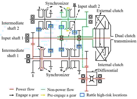
Figure 1.
Structure diagram of dual clutch transmission.
The internal and external clutches of the transmission correspond to the input inner shaft and outer shaft respectively. Gears 1, 3, 5, and 7 are driven by the input inner shaft, and gears 2, 4, 6 and R are driven by the input outer shaft. Under the dual clutch automatic transmission in the primary block strategy, by controlling the two-clutch combine alternately, which can realize power without interruption shift, with 1 in the primary 4 block as an example, the clutch under the impetus of the piston within the transmission torque, and the power passes through the inner clutch. The input shaft 1 is transmitted to the driving gear and driven gear of the 1st gear, and finally through the main reducer, differential, and half shaft which is connected and passed around. At this time, the external clutch, external input shaft 2 and the output shaft 2 do not transmit power, but due to the meshing of the main reduction gear end of the output shaft and the 4th gear pre-selection at this time, the driven end of the external clutch, the external input shaft 2, and the output Shaft 2 also rotates with it.
On the power transmission route, because the synchronizer is not engaged, when the transmission torque fluctuates, the driving gear combined with the gears 3, 5, and 7 will have speed fluctuation, so there will be the risk of gear rattling. On the non-power transmission route, due to the pre- selection of the 4th gear, it is equivalent to inputting torque fluctuations to the external input shaft 2. At the same time, the input shaft 2 has the drag torque of the external clutch to cause it to rotate. and the empty sleeve gears in the gears 2, 4 and R will also rotate accordingly due to the friction of the needle roller bearings and synchronizer. Thus, the idler gear of the 1st, 3rd, and 5th gears may also be at risk of rattling on the non-power transmission route.Therefore, the gears that may produce rattling are shown in Table 1.

Table 1.
Possible rattling gears under two working conditions. (Note: “o” means rattling is possible; “×” means rattling is impossible).
Therefore, in order to explore the influence of the preselected gear strategy on the rattling characteristics of the dual-clutch transmission, this paper established the gear rattling dynamics model of the 1st gear without preselection, the 1st gear preselected and the 4th gear for related research, as shown in Figure 2. The mathematical model is shown in Equations (1) and (2):
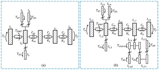
Figure 2.
Schematic diagram of dynamic model of multi-gear rattling: (a) 1st gear; (b) 1st gear pre-selection 4th.
Without pre-selection
With pre-selection
where is the moment of inertia of the engine and the primary flywheel, is the sum of the moment of inertia of the inner input shaft + secondary flywheel + clutch, is the gear idler gear moment of inertia, is the moment of inertia of the 1st gear, is the moment of inertia of the main reducer and differential, is the moment of inertia of the half shaft and loading motor, is the outer moment of inertia The moment of inertia of the input shaft and the outer clutch driven plate, is the moment of inertia of the 6th gear, is the moment of inertia of the 2nd gear, is the moment of inertia of the reverse gear, and are the torsional stiffness and torsional damping of the output shaft, and are the torsional stiffness and torsional damping of the half shaft, respectively; (i = 2, 3, 5, 6, 7, R) and are the drag torque generated by the idler gear and clutch in each gear, is the base circle helix angle of each gear, is the base circle radius of the main and driven gears of each gear, and is the transmission torque of the dual-mass flywheel torsion damper:
where and are the primary and secondary damping stiffnesses of the dual-mass flywheel torsional damper, respectively, and are the idle travel angle of the torsional damper and the working angle of the primary damping stiffness, and is the torsion of the dual-mass flywheel. The dry friction resistance torque of the shock absorber, is the maximum torque of the engine, .
2.2. Gear Contact Model
The model established in this paper is a dynamic model with the lubrication effect considered. Therefore, the gear meshing force in the lubrication state includes two aspects: the dynamic meshing force generated by direct contact of gear teeth and the fluid lubrication force generated by extrusion and suction of lubricating oil when the tooth surfaces do not contact. The two contact forms are shown in Figure 3.
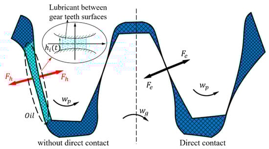
Figure 3.
Schematic diagram of gear contact form.
However, in the process of gear processing, in order to avoid thermal expansion jam, and to produce ideal lubrication, it is necessary to maintain adequate clearance. According to reference [] backlash is symmetrically distributed and lubricants exist between the two tooth surfaces and change the relative displacement of gears. Therefore, the backlash is expressed by the nonlinear deformation function , as shown in Equation (3):
where is the upper limit of the central oil film thickness at which the meshing force begins, is the nonlinear backlash affected by . The direct contact condition is regarded as a special case of lubrication condition, where there is no oil between the two tooth surfaces, i.e, .
Therefore, the meshing force of gears in the lubrication state can be expressed by piecewise function as shown in Equation (4)
where is the normal relative displacement of helical gear, is half of the backlash, and represent the base circle radius of the main and driven gears respectively, is the time-varying meshing stiffness of the gear, and is the gear meshing damping [,] which can be expressed as:
where represents the damping ratio coefficient, which usually ranges from 0.03 to 0.17, and the value in this paper is 0.1.
In this paper, the potential energy method [,,] is used to calculate the time-varying mesh stiffness of the helical gear pair. The potential energy method divides the gear mesh stiffness into hertzian contact stiffness and bending stiffness , shear stiffness , axial compression stiffness , matrix stiffness , and the stiffness of each part is connected in parallel to obtain the time-varying mesh stiffness of the helical gear pair, which is:
The time-varying meshing stiffness of partial gears of transmission calculated based on the potential energy method is shown in Figure 4. The dotted line represents the time-varying meshing stiffness of a single gear tooth, and the solid line represents the comprehensive meshing stiffness considering the simultaneous meshing of multiple teeth.
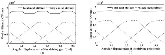
Figure 4.
Mesh stiffness of helical gear: (a) 1st gear; (b) 4th gear.
When the tooth surfaces do not contact, the lubricating oil between the two meshing teeth can be regarded as a nonlinear elastic-damping element with time variation. Under the action of tooth surface extrusion and coiling, the fluid lubrication force is produced, which will affect the dynamic response of the gear meshing. The mathematical model of the oil film force is summarized as Equations (7)–(9):
where the and are equivalent damping coefficients of coiling and extrusion, respectively; represents the meshing curve of the helical gear, represents the equivalent radius of the curvature of the gear, represents oil film thickness, is the oil film extrusion speed, represents the dynamic viscosity of the lubricating oil, represents the distance between tooth profiles, the and represent the rolling speed of the tooth surface of the main and driven gears. is to avoid that the calculated value of Equation (7) tends to be infinite when becomes null, so a saturation value was adopted, let = 10, where represents the mean roughness [] the is the suction speed of lubricating oil.
2.3. Drag Torque
The drag torque in the dual clutch transmission mainly includes two forms: gear drag torque and wet clutch drag torque, Since the torque of the gear power transmission is much larger than the drag torque, the bearing gear in this paper ignores the influence of the drag torque, while ignoring the main wind resistance.
The drag torque [,] of the idle gear mainly includes three aspects: the gear oil stirring resistance torque , the roller bearing torque and the oil film shear resistance torque . Fuether, the gear oil churning resistance torque can be passed through the Formulas (10)–(12) and calculated as follows:
where is the lubricating oil density, is the angular velocity of the idle gear, is the oil immersion area, is the gear pitch circle radius, is the oil immersion depth, V is the lubricating oil volume, is the Froude number, is the Reynolds number, is the tooth width, and is the kinematic viscosity of the lubricating oil.
In the method of reference [] the bearing resistive torque is shown in Equation (13)
where is the lubrication factor, which is related to the type of lubricant and lubrication method, and its value can be referred to the standard ISO TR 14179-2-2001, is the speed difference between the driven gear and the shaft; is the average diameter of the bearing.
The oil film shear torque is mainly the resistance torque caused by the relative motion between the inner cone surface of the synchronizer lock ring and the outer cone surface of the gear friction when the synchronizer is not combined, and the mathematical expression is:
where is the lubricant dynamic viscosity, is the length of the tapered surface, is the average radius of the tapered surface, and represents the clearance between the tapered surfaces of the synchronizer ring and the synchronizer gearing.
In summary, the total no-load gear dragging torque can be expressed as:
The clutch drag torque is related to the state of the lubricating oil between the friction disc gaps []. Under the influence of the relative rotational speed of the friction disc, the flow rate and the viscosity of the lubricating oil, there are three states of the lubricating oil between the friction disc gaps: the oil film state, the mixed state of the oil film and the oil mist state, and the pure oil mist state, as shown in Figure 5. In the figure, , and are the inner diameter of the friction disc, the outer diameter of the friction disc and the critical radius, respectively, and the calculation expression is as in Equation (16).
where lubricating oil flow, clutch disc clearance, and are the speed difference between driven disc and clutch disc, respectively; and are the inner diameter and outer diameter of clutch disc, respectively.
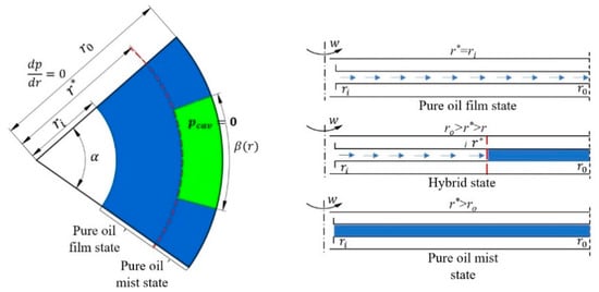
Figure 5.
Schematic diagram of the lubrication state between clutch discs.
According to the oil film state of lubricating oil, the mixed state of oil film and oil mist and the pure oil mist state in the friction disc gap, the towed torque , and can be calculated by Equations (17)–(20) respectively, where N is the number of friction pairs.
Therefore, the total clutch drag torque is summed in three ways:
As shown in Figure 6, when the lubricating oil between the clutch discs is in the state of oil film, with the increase of in the relative speed, the drag torque gradually increases; when the lubricating oil is in a mixed state or an oil mist state, the drag torque gradually decreases with the increase in the relative rotational speed.
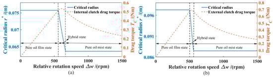
Figure 6.
Clutch disc drag torque: (a) Internal clutch; (b) External clutch.
2.4. Model Validation
In order to verify the accuracy of the proposed model, the dual-clutch transmission was tested on the three-motor test stand (Figure 7) to obtain the test data. Considering that the coupling between the power flow gear and the no-load or light-load gear is not strong, the whole dual-clutch transmission is selected for the test. The main motor of the stand is directly connected to the transmission using a rigid shaft, so that the 2 second order engine excitation simulated by the N/T control mode controls the motor to be transferred directly to the transmission input shaft, outputting a continuously fluctuating speed, and the two secondary motors are connected to the two half shafts of the transmission to simulate the load torque. Most transmission bench tests collect vibration and noise signals, which makes it difficult to compare with the simulation results. In this study, a magnetoelectric speed sensor is used to measure the gear speed and the angular acceleration can be obtained. The motor parameters and test conditions are shown in Table 2.
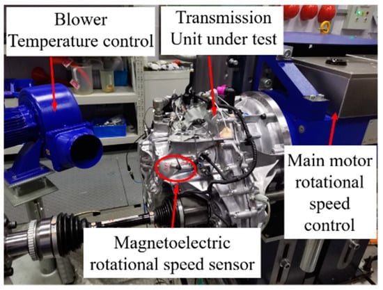
Figure 7.
Transmission test bench and speed sensor installation position.
Table 2.
Motor parameters and test conditions.
The results of the transmission rattle bench test are shown in Figure 8, the analysis found that with the increase of the input angular acceleration excitation, the vibration signal of transmission shell takes a step phenomenon, and there was a broadband component, that is, a rattling phenomenon occurred. Comparing with the vibration acceleration of the transmission case under no pre-selection and pre-selection gears, after 50 s, the casing vibration acceleration under the pre-selection gear is significantly higher than that without pre-selection gear, and the vibration acceleration signal fluctuation under the pre-selection gear is more obvious. The test results show that the dual clutch transmission is more prone to rattle in the pre-selected gear state. At the same time, under the condition that the simulation conditions and the test are consistent, the dynamic response of the torque fluctuation to the gear rattle is numerically calculated, and the angular acceleration value under the second-order excitation frequency (50 Hz) of some idle gears is compared with the test results, as shown in Figure 9.
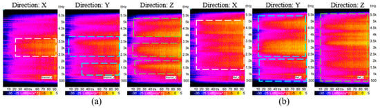
Figure 8.
Colormap of vibration acceleration at bearing: (a) 1st gear; (b) 1st gear pre-selection 4th.
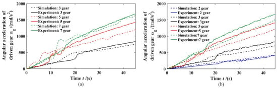
Figure 9.
Angular acceleration amplitude of idler gear: (a) 1st gear; (b) 1st gear pre-selection 4th.
From the Figure 9, it can be found that the trend of the simulation results and the test results are in good agreement, but there is a certain error in the amplitude. There are two possible reasons for the error: (1) it is related to the vibration of the table and the installation of the gearbox, and as the fluctuation amplitude increases, it causes the vibration of the test bench and the transmission input shaft to increase, resulting in large test results; (2) the dynamics model established is somewhat simplified compared with the actual one. However, the errors on the results are within the acceptable range. Therefore, the simulation model can be used for further parametric analysis.
3. Numerical Simulations and Analysis
The main factors affecting gear rattling include torque fluctuation, drag torque and lubricating oil viscosity, etc. It is very important to find out the influence law of each parameter on the dynamic response of gear rattling. Therefore, we will use the proven rattle dynamics model to solve the equation with the 4/5 order Runge Kutta method, analyze the influence of the preselected gear on the dynamic response of each idler gear, and use the rattling evaluation index and power loss as a reference , compare the contribution of each idle gear to the rattle, and explore the influence of different parameters on the rattle of the transmission gear.
3.1. Rattling Evaluation Index and Power Loss
Due to the existence of backlash, the speed fluctuation of the input end of the transmission may cause the gear teeth to mesh and disengage during the movement process, resulting in irregular tooth surface rattling phenomenon, which is transmitted to the vehicle as a transmission rattle noise. For the evaluation method of the gear rattle, the rattling intensity can be described by using the rattling objective evaluation index. In this paper, the gear meshing power is used as the rattling evaluation index to explore the influence of different parameters on the gear rattle intensity, as shown in Equations (22) and (23):
where is the meshing power and is the gear relative speed.
The above gear rattling indicators are for a single pair of gear pairs, and the overall transmission rattling indicators are shown in Equation (24), where is the rattling index of the i-th gear.
The power loss calculation in this paper mainly considers the power loss caused by lubrication [], and analyzes the influence of different factors on the system efficiency. The total power loss is composed of the dissipation power generated by the oil film squeeze damping effect, the dissipation power generated by the viscous moment, and the dissipation power generated by the churning resistance torque, which can be calculated by the following formula:
The viscous torque can be obtained by Petrov's friction law []:
where is the contact length between the gear shaft and the gear shaft, is the radius of the gear shaft, and is the clearance between the gear shaft and the gear shaft.
3.2. Dynamic Response
3.2.1. 1st Gear without Preselection
In the state of 1st gear without preselection, the gear pairs that may be rattled include gears 3, 5, and 7, and other idle gears are less likely to be rattled when low-viscosity lubricating oil is used without preselection. Therefore, this section will focus on analyzing the dynamic response of the 3rd, 5th, and 7th gear pairs of DCT under the condition of input torque fluctuation, and will calculate the rattling intensity of each idler gear and the DCT as a whole based on the rattling evaluation index.
Figure 10a,b, Figure 10c,d and Figure 11 are the dynamic responses of the idler gears of the 3rd, 5th and 7th gears in the 1st gear without pre-selection state, respectively. As can be seen from the relative displacement curve of gear 3rd in Figure 10a, with the increase in angular acceleration fluctuation, the form of the gear rattling changes. Within 0–10 s, the relative displacement curve contacts with the red dashed line representing the half-backlash, indicating that the gear drive side is in direct contact at this stage, and a single-sided rattle occurs. The meshing force of gear 3rd shown in Figure 10b can also be seen that the gear is stressed on one side within 0–10 s; however, a sudden change occurs around 10.9 s, whereby the relative displacement begins to oscillate back and forth between the gaps on both sides. In addition the meshing force of the 3rd gear increases instantaneously, and there are positive and negative meshing forces at the same time, indicating that the gear pair begins to have double-sided rattling at this time. The relative displacement of the gear pair fluctuates within 10.9–45 s and the meshing force increases with the torque fluctuation, which are both a double-sided rattle, and the rattle intensity gradually increases.
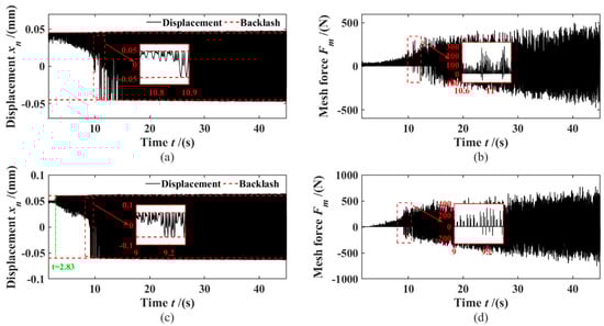
Figure 10.
Dynamic response: (a) 3rd gear relative displacement; (b) 3rd gear meshing force; (c) 5th gear relative displacement; (d) 5th gear meshing force;.
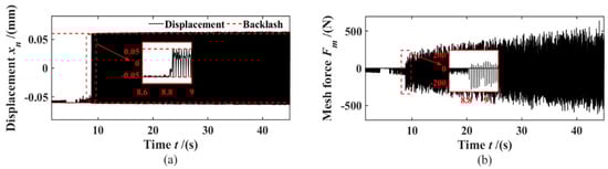
Figure 11.
Dynamic response: (a) 7th gear relative displacement; (b) 7th gear meshing force;.
As shown in Figure 10c, within 0–2.83 s, the relative displacement curve of the 5th gear did not contact the red dotted line representing the half-backlash, and the meshing between the teeth at this stage was very small, close to 0, indicating that the gears at this stage of the tooth surfaces are not in direct contact; however the power is transmitted by squeezing or coiling the oil film between the clearance, without rattling. As the torque fluctuation continued to increase, the sudden change in unilateral rattling occurred within 2.83–9.2 s, at which time the meshing force began to surge. Then at 9.2 s, the dynamic response of the gear undergoes a further sudden change, in which the 5th gear begins to oscillate back and forth between the two sides of the gap, and the meshing force increases instantaneously, and there are positive and negative meshing forces, indicating that the gear began to have double-sided rattling at this time. The dynamic response of the 7th gear pair shown in Figure 11a,b reflects a phenomenon similar to that of the 3rd gear pair.
3.2.2. 1st Gear Pre-Selection 4th
In order to further explore the influence of pre-selected gears on the overall rattling strength of DCT and the rattling strength of each idle gear, this paper builds a dynamic model of 1st gear pre-selection 4th gear. Under this working condition, gear pairs in 3rd, 5th and 7th gear will not be affected by the preselected gear strategy; therefore, gear rattling will always occur under certain excitation, and by comparing the relative displacements and meshing force of the 3rd, 5th, and 7th gear pairs before and after the preselected gear, it can be found that the preselected gear strategy has little effect on the dynamics of the 3rd, 5th, and 7th gear pairs. Except for the 7th gear from 0 to 9.6s, the gear pair is tightly fitted on the non-drive side, and the gear does not rattle at this time.
Figure 12, Figure 13, Figure 14 and Figure 15 are the dynamic responses of the idler gears of the 2nd, 4th, 6th and reversr gears in the 1st gear with pre-selection state, respectively. Gears 2, 4, 6, and R are driven by the DCT outer input shaft to generate the gear rattle. Taking the dynamic response of the 2nd gear pair shown in Figure 12a,b as an example, in the range of 0–13 s, the relative displacement contact on the positive backlash, the phenomenon of “impact-separation-impact” occurs on the gear drive surface at this stage, and the gear meshing force is all positive, indicating that the gear pair has a single-sided rattle at this stage; in the range of 13–45 s, the gear pair begins to oscillate between the backlash gradually, and there is an alternating positive and negative meshing force, and the gears are struck on both sides. However, the 4th and 6th gears both behave as double-sided rattling during the overall torque fluctuation change, which may be caused by the further increase in torque fluctuation when the torque transmitted by the internal input shaft is transmitted to the external input shaft 2 through the gears 1 and 4 and the reduction gears 1 and 2. At the same time, compared with the 3rd, 5th, and 7th gears, the gear meshing force of the 2nd, 4th, 6th, and R gear pairs is larger. The reason is that after the amplification of the gear ratios of the 1st and 4th gears, the torque fluctuation excitation transmitted to the external input shaft 2 is larger, thus causing the 2nd, 4th, 6th and R gear pairs to rattle more seriously.
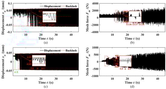
Figure 12.
Dynamic response: (a) 2nd gear relative displacement; (b) 2nd gear meshing force; (c) 3rd gear relative displacement; (d) 3rd gear meshing force;.
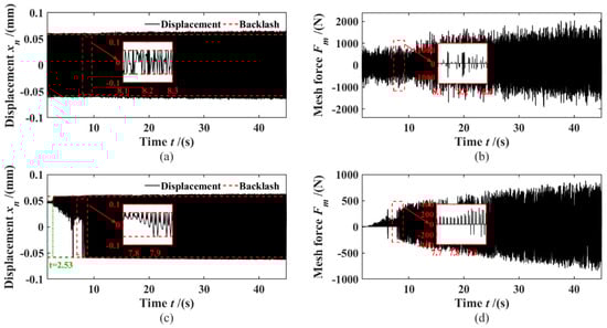
Figure 13.
Dynamic response: (a) 4th gear relative displacement; (b) 4th gear meshing force; (c) 5th gear relative displacement; (d) 5th gear meshing force;.
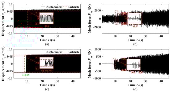
Figure 14.
Dynamic response: (a) 6th gear relative displacement; (b) 6th gear meshing force; (c) 7th gear relative displacement; (d) 7th gear meshing force;.
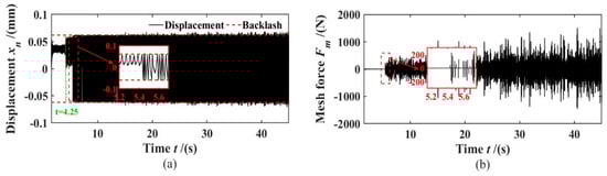
Figure 15.
Dynamic response of reverse gea: (a) relative displacement; (b) meshing force.
Based on this, the rattling evaluation index was used to compare the rattling intensity of each idle gear and the overall DCT of the two dynamic models with or without the pre-hanging strategy, as shown in Figure 16. The analysis found that the time point of the sudden change in the rattling index basically corresponds to the time point of the sudden change in the rattling situation of each gear in each working condition, and the gear corresponding to the sudden change point began to produce double-sided rattling.
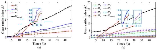
Figure 16.
Gear rattling strength: (a) 1st gear; (b) 1st gear pre-selection 4th.
At the same time, as shown in Figure 17, comparing the gears and the overall rattling intensity in the two cases, it can be found that the gears in the power flow gear are not affected by the pre-selected gear strategy, and the selection of the pre-gear aggravates the rattle of DCT. Considering that the rattling change in the 5th gear is more obvious, this paper will carry out a parameter analysis of the 5th gear pair, and obtain the influence law of each parameter on rattling.
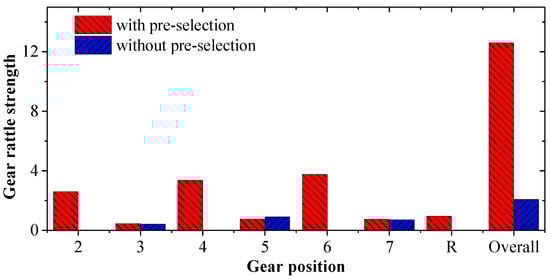
Figure 17.
Comparison of the rattling intensity of each gear.
3.3. Parameter Ananlysis
According to the conclusion in Section 3.2, the 5th gear pair is selected for parameter analysis, and the impact law of the input torque fluctuation, backlash, drag torque, moment of inertia and other factors on the gear rattle are explored by using the rattling evaluation index and power loss as a reference. Thus providing some theoretical basis for solving the problem of the transmission rattle.
The gear rattling vibration is affected by the lubricant viscosity , as shown in Figure 18a, with the increase in , the influence of the backlash on the gear rattling vibration becomes smaller and smaller, but lubricant viscosity has a great influence on the gear rattle. Furthermore appropriately increasing the dynamic viscosity can effectively reduce or restrain the gear rattle strength and improve the stability and NVH performance of the system. However, when the backlash is small, although the rattling vibration phenomenon of the gear is improved, the cost of improving the manufacturing precision will inevitably increase, so a larger backlash can be appropriately selected. As shown in Figure 18b, the coupling effect of viscosity and backlash has a great influence on the power loss of the system. Under different backlashes, the power loss changes roughly linearly with the change in lubricant viscosity. In order to improve the transmission efficiency of the gear, an appropriate large lubricant viscosity can be selected, and the backlash can be relaxed.
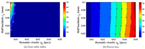
Figure 18.
Contour plots of gear rattling index and power loss as a function of lubricant viscosity and backlash: (a) Gear rattle index; (b) Power loss.
Since the viscosity of the lubricant is one of the important factors affecting the drag torque, as shown in Figure 19a, by analyzing the influence of the drag torque on the rattling characteristics of the gear, it can be found that the effect of the viscosity of the lubricant on the rattling characteristics is basically the same, that is, a larger drag torque can effectively suppress the rattling, but an excessive drag torque will increase the power dissipation of the system.
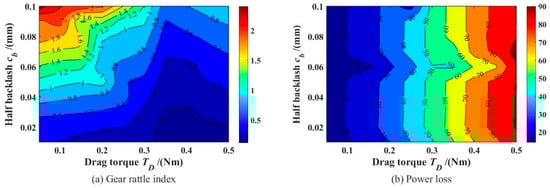
Figure 19.
Contour plots of gear rattling index and power loss as a function of dragging torque and backlash: (a) Gear rattle index; (b) Power loss.
In the same way, when we analyze the influence of the input torque fluctuation and idle gear rotational inertia on gear rattle, as shown in Figure 20 and Figure 21, it can be found that the torque wave has a great influence on the system rattling, with the change in torque fluctuation showing the trend of linear increase, and is greatly affected by the backlash coupling effect, when the torque fluctuation and backlash are both large, the gear rattling will become very serious. However, the coupling effect of the two has a limited impact on the power loss of the system. With the increase in the moment of inertia, the rattling strength of the gear and the power loss of the system show an increasing trend, but the influence on the power loss is limited. Therefore, in order to reduce or suppress the gear rattle strength and improve the system efficiency, it is necessary to reduce the torque fluctuation at the input of the system as much as possible, and appropriately reduce the moment of inertia of the idler gear.
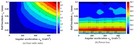
Figure 20.
Contour plots of gear rattling index and power loss as a function of torque fluctuation and backlash: (a) Gear rattle index; (b) Power loss.
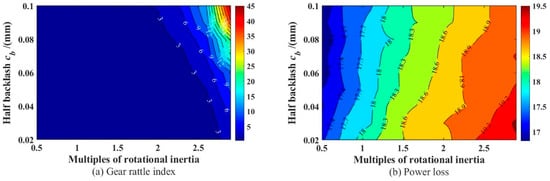
Figure 21.
Contour plots of gear rattling index and power loss as a function of moment of inertia and backlash: (a) Gear rattle index; (b) Power loss.
4. Summary
(1) Aiming at the rattling problem of a certain type of wet dual-clutch transmission, a multi-speed rattling dynamic model of the transmission is established, and the model considers the influence of the preselected gears on the transmission rattling. The validity of the dynamic model is verified by the transmission rattle bench test.
(2) Observing the gear angular acceleration curve of each gear in the 1st gear and the preselected 4th gear, it can be found that the preselected gear does not have a great impact on the gears that have been rattled in the non-preselected state; after the preselected gear, the reason why the DCT rattling phenomenon is more obvious is that due to the influence of the transmission power flow branch and the gear ratios at all levels, the torque fluctuation of the non-power flow shaft is intensified, and the number of idle gears that may cause rattling risk increases, thus increasing the overall rattling strength.
(3) With the increase in , the influence of the backlash on the vibration of gear rattling becomes smaller and smaller, and the viscosity of the lubricant increases, which can reduce the rattling intensity; a larger drag torque can effectively suppress rattling, but excessive drag torque will increase system power dissipation. With the increase in torque fluctuation, the rattling strength increases linearly, and is greatly affected by the coupling effect of the side gap, but the effect of the coupling effect on the system power loss is limited. Therefore, in order to improve the transmission efficiency of the gears, a larger lubricant viscosity can be appropriately selected, the backlash can be relaxed, the moment of inertia of the idle gear can be appropriately reduced, and a dual-mass flywheel or centrifugal pendulum clutch can be used as much as possible. This is done to attenuate the torsional vibration of the system, in order to achieve the effect of reducing the torque fluctuation at the input end of the system.
In this paper, a variety of factors are combined to model, and explore the influence of the pre-selection strategy on the transmission rattle characteristics, and to analyze the influence of different factors on the gear rattling intensity, which provides a theoretical research basis for solving the rattling problem of dual-clutch transmissions.
Author Contributions
D.G. and Q.N. participated in the formula derivation, analyzed the data, drafted the manuscript, and conducted constructive discussion and analysis. S.G. and Y.Z. participated in research design. R.L. contributed to data analysis. All authors have read and agreed to the published version of the manuscript.
Funding
This project was supported by National Natural Science Foundation of China (Grant No. 51975080, 52005067), Natural Science Foundation Project of Chongqing Science and Technology Commission (Grant No. cstc2019jcyj-msxmX0733), the Science and Technology Research Program of Chongqing Municipal Education Commission (Grant No. KJQN201901121), Youth project of science and technology research program of Chongqing Education Commission of China (No. KJQN201901115) and Chongqing Universities Innovation Research Group Project (No. CXQT21027).
Data Availability Statement
The datasets generated during and/or analysed during the current study are available from the corresponding author on reasonable request.
Acknowledgments
Thanks to Magna PT Powertrain (Jiangxi) Co., Ltd for providing the bench test to this research project. And all individuals included in this section have consented to the acknowledgement.
Conflicts of Interest
The authors declare that there is no conflict of interest.
References
- Yoon, J.Y.; Kim, B. Gear rattle analysis of a torsional system with multi-staged clutch damper in a manual transmission under the wide open throttle condition. J. Mech. Sci. Technol. 2016, 30, 1003–1019. [Google Scholar] [CrossRef]
- Wang, M.Y.; Zhao, W. Numerical Modelling and Analysis of Automotive Transmission Rattle. J. Vib. Control 2016, 8, 921–943. [Google Scholar] [CrossRef]
- Bozca, M. Torsional vibration model based optimization of gearbox geometric design parameters to reduce rattle noise in an automotive transmission. Mech. Mach. Theory 2010, 45, 1583–1598. [Google Scholar] [CrossRef]
- Chen, M.; Wang, D. Application of cae in design optimization of a wet dual cutch transmission and driveline. SAE Int. J. Passeng. Cars-Mech. Syst. 2014, 7, 1128–1137. [Google Scholar] [CrossRef]
- Yi, Y.; Huang, K.; Xiong, Y.; Sang, M. Nonlinear dynamic modelling and analysis for a spur gear system with time-varying pressure angle and gear backlash. Mech. Syst. Signal Processing 2019, 132, 18–34. [Google Scholar] [CrossRef]
- Theodossiades, S.; Tangasawi, O. Gear teeth impacts in hydrodynamic conjunctions promoting idle gear rattle. J. Sound Vib. 2007, 303, 632–658. [Google Scholar] [CrossRef]
- Brancati, R.; Rocca, E.; Russo, R. A gear rattle model accounting for oil squeeze between the meshing gear teeth. Proc. Inst. Mech. Eng. Part D J. Automob. Eng. 2005, 219, 1075–1083. [Google Scholar] [CrossRef]
- Brancati, R.; Rocca, E.; Russo, R. An analysis of the automotive driveline dynamic behaviour focusing on the influence of the oil squeeze effect on the idle rattle phenomenon. J. Sound Vib. 2007, 303, 858–872. [Google Scholar] [CrossRef]
- Rahnejat, H.; Gohar, R. The vibrations of radial ball bearings. Proc. Inst. Mech. Eng. Part C J. Mech. Eng. Sci. 1985, 199, 181–193. [Google Scholar] [CrossRef]
- Cruz, M.D.l.; Theodossiades, S. Transmission drive rattle with thermo-elastohydrodynamic impacts numerical and experimental investigations. Int. J. Powertrains 2011, 1, 137–161. [Google Scholar] [CrossRef]
- Wei, Z.; Shangguan, W.-B.; Liu, X. Modeling and analysis of friction clutches with three stages stiffness and damping for reducing gear rattles of unloaded gears at transmission. J. Sound Vib. 2020, 483, 115469. [Google Scholar] [CrossRef]
- Changenet, C.; Velex, P. A Model for the Prediction of Churning Losses in Geared Transmissions—Preliminary Results. J. Mech. Des. 2007, 129, 128–133. [Google Scholar] [CrossRef]
- Li, Z.; Zhu, C.; Liu, H.; Gu, Z. Mesh stiffness and nonlinear dynamic response of a spur gear pair considering tribo-dynamic effect. Mech. Mach. Theory 2020, 153, 103989. [Google Scholar] [CrossRef]
- Li, S.; Wu, Q.; Zhang, Z. Bifurcation and chaos analysis of multistage planetary gear train. Nonlinear Dyn. 2013, 75, 217–233. [Google Scholar] [CrossRef]
- Liu, F.; Zhang, L.; Jiang, H.; Zhang, J. Nonlinear dynamic analysis of two external excitations for the gear system using an original computational algorithm. Mech. Syst. Signal Processing 2020, 144, 106823. [Google Scholar] [CrossRef]
- Wang, J.; Zhang, J.; Yao, Z.; Yang, X.; Sun, R.; Zhao, Y. Nonlinear characteristics of a multi-degree-of-freedom spur gear system with bending-torsional coupling vibration. Mech. Syst. Signal Processing 2019, 121, 810–827. [Google Scholar] [CrossRef]
- Cao, Z.; Chen, Z.; Jiang, H. Nonlinear dynamics of a spur gear pair with force-dependent mesh stiffness. Nonlinear Dyn. 2019, 99, 1227–1241. [Google Scholar] [CrossRef]
- Chen, Z.; Ning, J.; Wang, K.; Zhai, W. An improved dynamic model of spur gear transmission considering coupling effect between gear neighboring teeth. Nonlinear Dyn. 2021, 106, 339–357. [Google Scholar] [CrossRef]
- Fernandez-Del-Rincon, A.; Diez-Ibarbia, A.; Iglesias, M.; Viadero, F. Gear rattle dynamics: Lubricant force formulation analysis on stationary conditions. Mech. Mach. Theory 2019, 142, 103581. [Google Scholar] [CrossRef]
- Guo, D.; Chen, F.; Liu, J. Numerical Modeling of Churning Power Loss of Gear System Based on Moving Particle Method. Tribol. Trans. 2019, 63, 182–193. [Google Scholar] [CrossRef]
- Guo, D.; Zhou, Y.; Zhou, Y.; Wang, Y.; Chen, F.; Shi, X. Numerical and experimental study of gear rattle based on a refined dynamic model. Appl. Acoust. 2022, 185, 108407. [Google Scholar] [CrossRef]
- Robinette, D.; Beikmann, R.; Piorkowski, P.; Powell, M. Characterizing the Onset of Manual Transmission Gear Rattle Part II Analytical Results. SAE Int. J. Passeng. Cars Mech. Syst. 2009, 2, 1365–1376. [Google Scholar] [CrossRef]
- Qbal, S.; Al-Bender, F. Mathematical Model and Experimental Evaluation of Drag Torque in Disengaged Wet Clutches. ISRN Tribol. 2013, 2013, 206539. [Google Scholar]
- Liu, H.; Arfaoui, G.; Stanic, M. Numerical modelling of oil distribution and churning gear power losses of gearboxes by smoothed particle hydrodynamics. Proc. Inst. Mech. Eng. Part J J. Eng. Tribol. 2018, 233, 74–86. [Google Scholar] [CrossRef]
Publisher’s Note: MDPI stays neutral with regard to jurisdictional claims in published maps and institutional affiliations. |
© 2022 by the authors. Licensee MDPI, Basel, Switzerland. This article is an open access article distributed under the terms and conditions of the Creative Commons Attribution (CC BY) license (https://creativecommons.org/licenses/by/4.0/).