1. Introduction
Modular spreader beams are the staple products of lifting companies such as Durham Lifting Ltd. [
1], which is located in England and actively supports the local industries by providing heavy-duty lifting operations. Durham Lifting designs and supplies modular spreader beams; the respective product range under the brand MultiSec will be the key focus of this paper [
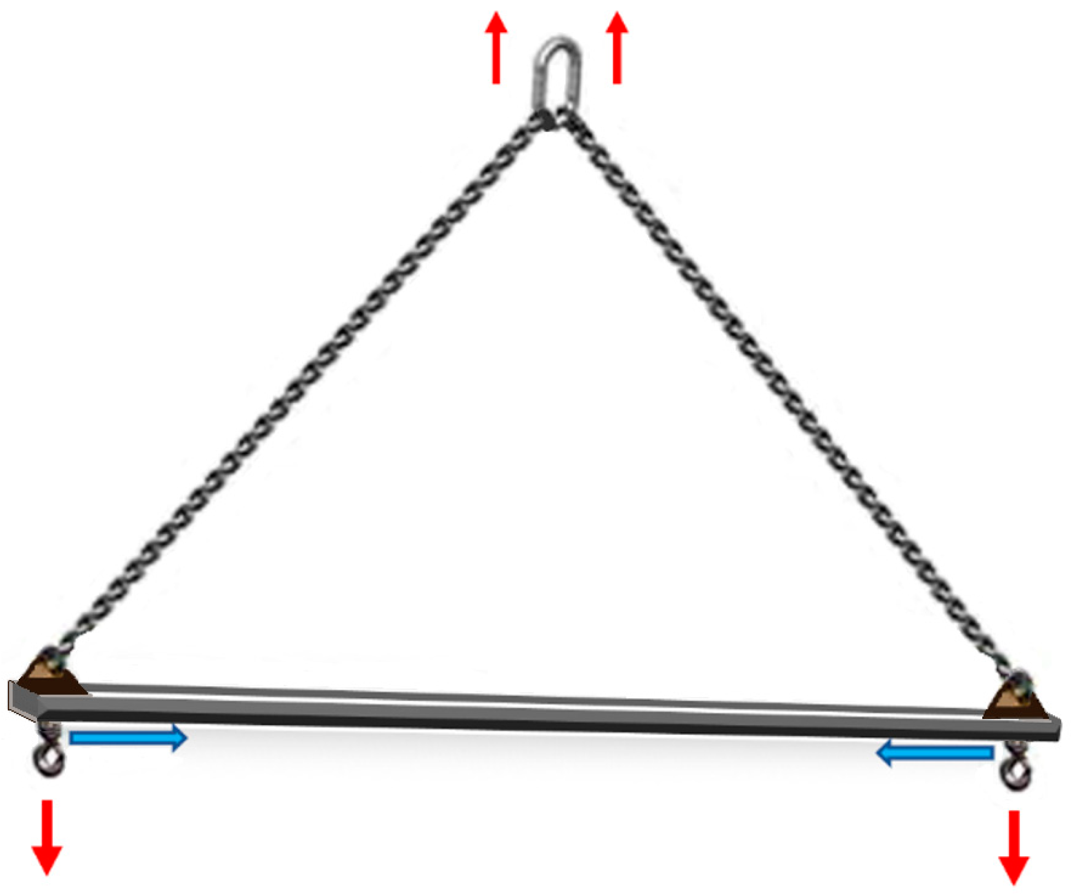
2]. A spreader beam is a simple device consisting of a long bar that holds two slings apart. When a lifting load is applied, the spreader beam encounters pure compressive force while the slings undergo tensile force, as displayed in
Figure 1. Assuming that the load’s centre of gravity is central to the spreader beam and the two header slings are symmetrical, the slings are then subjected to the same tensile force. Resolving for each side, the vertical force on one side will be half the total weight of the beam and what it is carrying. This can be converted into the sling tension to determine the compressive force in the beam [
3]. This is equal to the total compression as the beam is in equilibrium, where the compressive force on the other end of the beam will be equal and opposite [
4]. According to Eurocode 3 BS EN 1993-1-1:2005, the stress resulting from the compressive force must be two times below the yield stress of the material [
5], which in this case is steel grade S355, with the yield strength of 355 MPa [
6]. The resulting stress value can be used to determine the appropriate spreader beam size for safe lifting operation.
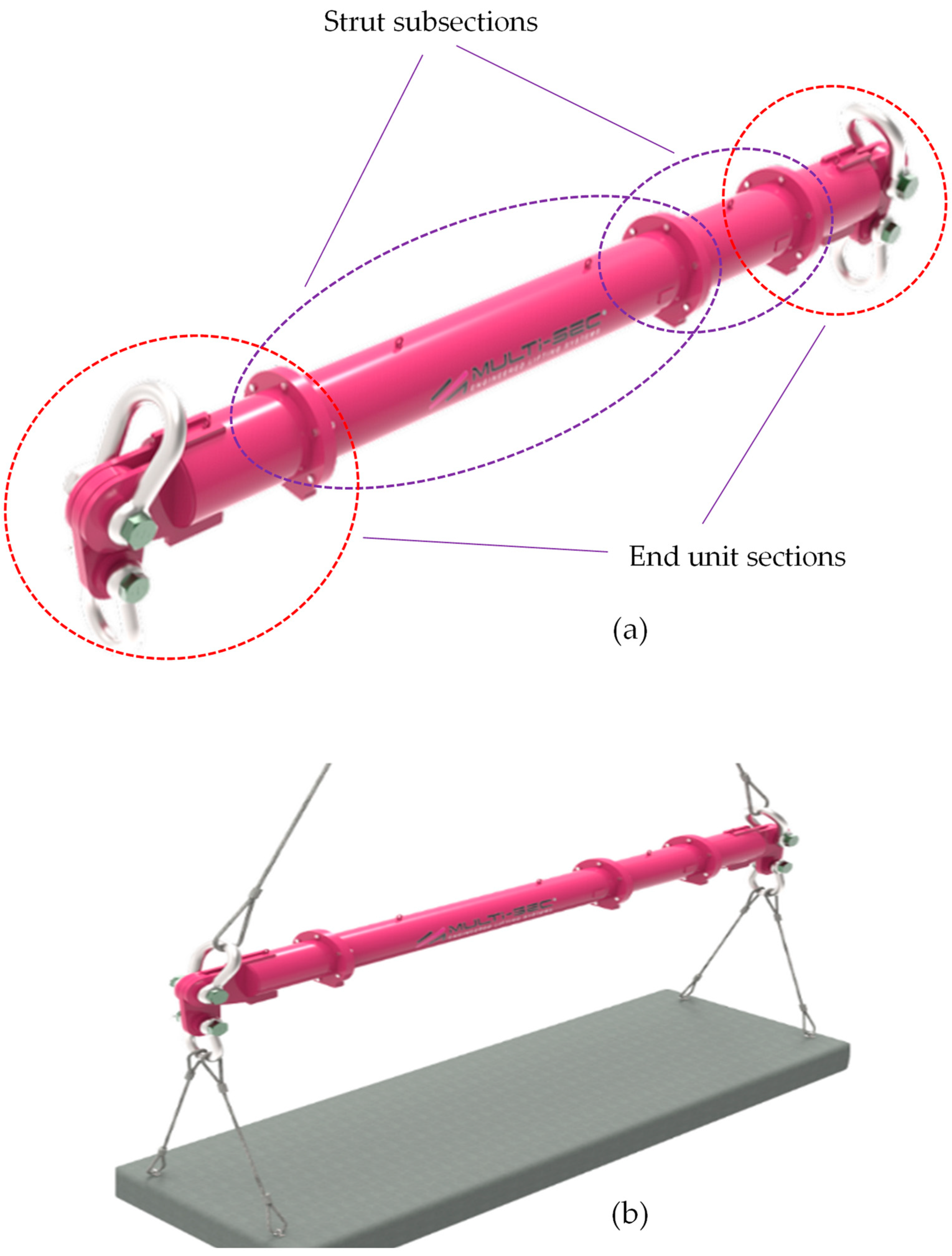
The spreader beams are required to be operated with the load’s centre of gravity directly in line with the crane hook. This ensures that the lift is balanced and stable. The size of items being lifted can vary widely, therefore beams of various lengths are required. Using modular spreader beams allows the manufacturer to create the desired total beam length from multiple sections with smaller lengths using prefabricated parts. This offers flexibility, meaning that customers can have various lengths of beams to cope with different payloads.
Figure 2 shows a sample of the MultiSec range assembled by Durham Lifting to comply with a certain length as per a client’s payload size which is composed of four strut sections and two fixed-size end units holding shackles and drop links [
2].
The flexibility provided by the MultiSec range is more cost-effective for the customer as this is now an off-the-shelf product and does not need to be bespoke. While it is essential that appropriate beam lengths are supplied to meet the customer’s requirements, this flexible product also causes less manufacturing cost and time for the seller. The main issue, however, is dividing the total required length into smaller sizes and determining the optimal arrangement of smaller beam sections to be used on demand. Furthermore, in order to supply a set of beam sections to the customer that can be reconfigured to supply any required length, an optimal approach is essential to determine the minimum number of beam sections, generating all of the required lengths. The lower the total number of sections supplied to create this package, the better for both the customer and the company as it would be cheaper for the customer while the manufacturer also incurs less labour cost and time.
In the absence of an automated system to determine the optimal arrangement of the required MultiSec and number of beam sections, the manual process takes a significant amount of time. Furthermore, the risk of making a mistake in the manual process cannot be ignored; therefore, the time taken from checking to approval is considerably long. This eventually causes delays in generating quotes for customers.
Therefore, a tool which enables automation of this process and calculates these sizes instantly is essential. This tool, which has now been developed and has led to spending much less time, is a programme to divide the modular spreader beam’s total length into minimum required number of subsections in an optimal way. Hence, the customer can receive the quotation much faster, which also leads to more conversions from enquiries to sales. Furthermore, admin staff in the sales team who may not be engineers will also be able to calculate the required beam configuration using the automated system, which is advantageous as it means that highly technical staff can be less involved.
The tool to calculate the optimal subsections to create the full beam assembly uses a custom-made optimization algorithm to determine which configuration of sections will use the lowest number of sections to create an assembly of the desired length. The automated system can perform the calculation repeatedly for a wide range of desired total lengths. The manual process requires at least one engineer to spend more than one hour to work out the optimal configuration in addition to considerable time required for rechecking and approval, while the automated system reduces this process time to a few seconds and eliminates the risk of human errors. The company could then sell or hire out their modular spreader beams as a set that can be used to create several lengths, meaning the customer need only purchase or hire one package and can reconfigure the modular spreader beam to create as many different lengths as needed depending on the payload dimensions.
In this paper, the aim is to develop an automated system using dynamic programming to improve the efficiency in an engineering business. The expectation is that the programme automates engineering calculations and creates an activity-based costing system to deliver a quote accurately and quickly. It would then enable the company to offer a price for the supply of a system instantly which could be carried out even by a non-expert sales staff member. The way this process is developed is discussed along with the advantages of such a system. The next section provides a research background on costing systems and the techniques to improve these systems, which is followed by explaining the overall structure of the developed algorithm where the input parameter is the range of total lengths, and the final output is the optimal number of required subassembly sections. Finally, the effectiveness of the algorithm is demonstrated.
2. Literature Review of the Approach
The first step needed to be taken was to explore if there is any existing explicit approach to solve this problem. A similar issue to this challenge is calculating the coins needed to give change, which could be set as the starting point. There are two methods commonly used for this issue: greedy algorithm, and dynamic programming [
7,
8]. The greedy algorithm is a search algorithm that works from the “top-down”, meaning that the algorithm searches through possible solutions and only considers the current selection, disregarding other possible solutions. This is carried out from the “top-down” from largest to smallest value [
7,
9]. One of the main advantages of a greedy algorithm is that it is effective in finding an approximate solution to complex combinatorics problems with a computation time that increases linearly with the number of combinations. Hence, it could accomplish the solution through very few steps, much quicker than other methods [
10]. The main issue of the greedy search is that although it will find an appropriate approximation of a combinatorics problem, this may not always be the best solution, as the algorithm only works locally on the current problem which means it is likely to be confined in local extremums. Although the algorithm is simple, it might not produce the absolute optimal solution to a combinatorics problem and should only be used to find an approximation [
11].
Dynamic programming is another mathematical optimization method appropriate for solving the current problem; it was created in the 1950s by Richard Bellman [
12]. Dynamic programming has many applications across all areas of engineering, as well as other fields such as economics [
13]. The method is used to solve complex optimization problems by breaking these problems into smaller sub-problems and using recursion to test each subproblem [
7,
12]. However, dynamic programming is slightly different for using only plain recursion [
14]. Recursion can also be used for optimization, and it is where a large problem is solved by solving several smaller sub-problems related to the larger overall problem [
15]. A recursive function is a function that calls itself, meaning many layered loops [
16]. In an optimization problem, this will allow a recursive function to check all possible outcomes to then determine the best solution. The issue with this approach is that the computation time increases exponentially with an increase in combinations. This can result in a high run time [
17]. Furthermore, using recursion to solve combinatorics problems can result in the large number of iterative processes, which is computationally expensive. An example of this matter is to calculate the Nth Fibonacci number using recursion, which has a computation time that increases exponentially as N increases linearly. Therefore, recursion is only suitable when the number of combinations is low [
18].
Dynamic programming resolves this issue as it improves the recursion algorithm in a way that reduces the computational time, while retaining the same level of accuracy [
19]. Whilst optimizing a combinatorics problem, recursion will repeat the same calculation many times, which is slow. A dynamic programming approach will perform each calculation once and store the output if the calculation needs to be performed again. Hence, instead of recalculating the answer, the stored output is taken, which significantly increases the speed and efficiency of the program [
14].
As a preliminary proof that dynamic programming and recursion is advantageous over a greedy algorithm, a trial on the MultiSec range selection was carried out, as explained in the following. Assume that desired beam length is 1500 mm and it should be composed of sections with the following available lengths: 1000 mm, 750 mm, and 250 mm. A recursive algorithm would start with the largest section and check if it is suitable, it would then try to add more until a solution is found [
11]. The greedy algorithm would select the 1000 mm section as it is under the 1500 mm total length and then try to add sections to it. Another 1000 mm section could not be added as this would make the total length now 2000 mm which exceeds the required length, so the next smaller section is tried. A 750 mm section would be also too large as the total would become 1750 mm which is still larger than 1500 mm. The 250 mm section would then be tried which is suitable as the total length is now 1250 mm, which is under 1500 mm. This is then repeated, and, as the larger two sections are also too large, another 250 mm section is selected. The total length is now 1500 mm, comprising sections of length 1000 mm, 250 mm, and 250 mm, three sections in total. This is, however, not optimized to select the minimum number of sections. The optimal solution is a total length of 1500 mm comprising sections of length 750 mm and 750 mm, two sections in total. This is where the greedy algorithm fails. If the same problem was approached with dynamic programming or recursion, every possible solution would be calculated, leading to attainment of the true optimal solution.
3. Algorithm: The Optimal Selection Process of Subassembly Sections
The purpose of this section is to present the overall structure of the algorithm developed for automating the optimal selection process, as shown in
Figure 3. The input parameter is the required range of total lengths, and the final output is the optimal number of required subassembly sections. Initially, the input parameters are checked to determine if it is within an appropriate range; if so, the end unit lengths are subtracted from the total length. Otherwise, the input parameters are required to be regenerated.
Subsequently, the 2D arrays are created to store the lengths of subassembly sections. These 2D arrays may have to be recreated in accordance with the change of array size, when the required number of subassembly sections is updated. It is noted that the array is set up in such a way that (0, current length) until (0, maximum).
Once the 2D arrays are set up, there will be several looping processes. The process iteratively calculates the sections needed for each length between minimum length and total length, incrementing at the step size that is defined by the length of subassembly sections. This is performed with a for loop that loops (total – minimum)/step times, each time storing the values in a 2D array with each iteration along the first dimension and the section sizes in the second. This is then transposed into a 2D array, storing iteration number in the first dimension and quantities of each section size in an appropriate position in the second dimension. Finally, the maximum value for each specific section size is determined and added to a new array. This is repeated for every section size. This new array contains the quantity of sections needed in the position that correlates to the defined step size.
The program was originally coded using Python and was then translated into VBA (Visual Basic for Applications) in Microsoft Excel. The programme is easy to use, where a non-expert sales staff member could insert the input, execute the program, and finally obtain the output in a few seconds.
4. Results and Discussion
The code was developed with the approach of dynamic programming, and the concept is depicted in
Figure 3. The input parameter is the required range of total lengths, and the final output is the lowest number of required subassembly sections. Considering a particular total length as an input parameter
L, the
L is checked to determine if it is appropriate; if not, the
L needs to be reset for further processing. With appropriate value of
L, the first step is to subtract the length of both end units of subassembly sections. It is noted that the end unit lengths have a fixed value in relation to different MultiSec range. The resulting length
LR will then be used as a targeted length to determine the optimal combination of subassembly lengths. With the resulting length
LR, a 2D array dataset of related subassembly lengths is generated. Subsequently, the
LR is checked if
LR =
L [0][
m], which is to check if the
LR can be fitted with the subassembly length
L [0][
m]. If so, the value
m is updated; otherwise, it proceeds to the next step for further checking, where the checking conditions are
LR >
L [0][
m] and then
LR ≤ 1 +
L[
m][
n − 1]. Essentially, the aforementioned process is carried out continuously until the lowest number of sections of subassembly lengths is generated. The looping process is carried out repeatedly for a range of
LR values which cover the range of specified input total lengths. In this sense, the lowest number of sections of subassembly lengths that cater for a range of
LR values can be generated. This set of the lowest numbers of sections is then reorganized so that the maximum number of each subassembly section can be determined. This set of maximum numbers indicates the optimal number of subassembly sections that can cover the specified range of total lengths.
An example of results for the required number of subassembly sections is shown in
Table 1. In this example, the expectation is to determine the lowest number of subassembly sections for the required MultiSec range from 1500 mm to 8000 mm. It is noted that 750 mm is the end unit length of the subassembly sections, which is required from Multi 110 to Multi 250 as a structural constraint. From Multi 13 to Multi 75, the end units of 500 mm are used as a structural constraint. Referring to
Table 1, the 1500 mm MultiSec can be constructed by two subassembly sections, and 2000 mm MultiSec can be constructed by two subassembly sections of 750 mm and one subassembly section of 500 mm.
The algorithm operates in a similar manner for the remainder of the MultiSec range from 2500 mm to 8000 mm. The underlying idea is that by starting with two subassembly sections of 750 mm as the end units, the algorithm searches for the largest possible subassembly section length to be added up until the required length of MultiSec is achieved. Finally, the maximum values of each row will be taken as optimal values of subassembly sections. As such, for the MultiSec range of 1500 mm to 8000 mm, the respective subassembly sections are two set of 750 mm units, one set of 500 mm unit, one set of 1000 mm unit, one set of 2000 mm unit, one set of 4000 mm unit, and one set of 6000 mm unit.
5. Conclusions
The main contribution of this paper was to establish an automated process of determining the optimal values of subassembly sections of MultiSec range used in heavy-duty lifting machines. The underlying idea was to implement a dynamic search optimization program, which involved searching the optimal combination of the fewest subassembly sections to be assembled as a range of specified total lengths. It was somewhat similar to solving a max–min problem. Without the automated system, the time taken to work out the optimal combination of subassembly sections was considerably significant. The effectiveness of the programme was demonstrated, where the optimal number of subassembly sections can be now determined given a specified range of total lengths. This automated process can be incorporated into the costing process. Eventually, the time taken from the customer placing an order to provision of costing can also be shortened considerably, to a few minutes.
Author Contributions
Conceptualization, T.W.; methodology, T.W. and P.L.C.; software, T.W. and W.D.; validation, All authors; formal analysis, T.W.; investigation, T.W., P.L.C. and H.H.; resources, W.D.; data curation, T.W., P.L.C. and H.H.; writing—original draft preparation, T.W.; writing—review and editing, P.L.C. and H.H.; visualization, H.H.; supervision, P.L.C. and H.H.; project administration, W.D.; funding acquisition, none of authors. All authors have read and agreed to the published version of the manuscript.
Funding
This research was funded by the European Regional Development Fund (ERDF), grant number 34R18PO2599.
Conflicts of Interest
The authors declare no conflict of interest.
References
- Durham Lifting. 9 May 2022. Available online: https://durhamlifting.co.uk/ (accessed on 25 May 2022).
- Durham Lifting. Hire—Modular Spreader Beams for Hire—Multisec. 2022. Available online: https://www.multisec.co.uk/hire/ (accessed on 24 May 2022).
- Abbott, P.; Neill, H. Trigonometry: A Complete Introduction; Teach Yourself: London, UK, 2018. [Google Scholar]
- Strommen, E.N. Structural Mechanics: The Theory of Structural Mechanics for Civil, Structural and Mechanical Engineers; Springer International Publishing AG: Cham, Switzerland, 2020. [Google Scholar]
- Ungermann, D.; Kuhlmann, U. Eurocode 3. 1. Aufl; Beuth: Berlin, Germany, 2015. [Google Scholar]
- Matweb. Ovako S355J2 S355J2(M) Steel, +AR. 2022. Available online: https://www.matweb.com/search/datasheet.aspx?matguid=3c36b268408a4cc1ae7f789bd605d6c6&ckck=1 (accessed on 26 May 2022).
- Cormen, T.H.; Leiserson, C.E.; Rivest, R.L. Introduction to Algorithms; MIT Press: Cambridge, MA, USA, 1994. [Google Scholar]
- Goodrich, M.T.; Tamassia, R. Algorithm Design and Applications; Wiley: New York, NY, USA, 2014. [Google Scholar]
- Programiz. Greedy Algorithm. 2022. Available online: https://www.programiz.com/dsa/greedy-algorithm#:~:text=A%20greedy%20algorithm%20is%20an,if%20the%20choice%20is%20wrong (accessed on 26 May 2022).
- Gutin, G.; Yeo, A.; Zverovich, A. Traveling salesman should not be greedy: Domination analysis of greedy-type heuristics for the TSP’. Discret. Appl. Math. 2002, 117, 81–86. [Google Scholar] [CrossRef]
- Bang-Jensen, J.; Gutin, G.; Yeo, A. When the greedy algorithm fails. Discret. Optim. 2004, 1, 121–127. [Google Scholar] [CrossRef]
- Bellman, R. Dynamic Programming; Princeton University Press: Princeton, New Jersey, 1957. [Google Scholar]
- Adda, J. Dynamic Economics: Quantitative Methods and Applications; The MIT Press: Cambridge, MA, USA, 2003. [Google Scholar]
- Kartik, S. Beginners Guide to Dynamic Programming. 2021. Available online: https://towardsdatascience.com/beginners-guide-to-dynamic-programming-8eff07195667 (accessed on 4 May 2022).
- Graham, R.L.; Knuth, D.E.; Patashnik, O. Concrete Mathematics, 2nd ed.; Upper Saddle River: Bergen County, NJ, USA; Addison-Wesley: Munich, Germany, 2011. [Google Scholar]
- Epp, S.S. Discrete Mathematics with Applications, 5th ed.; Cengage Learning: Southbank, VIC, Australia, 2020. [Google Scholar]
- Dev. Practically Understanding Time Complexities of Recursive and Iterative Functions. 2021. Available online: https://medium.com/nerd-for-tech/practically-understanding-time-complexities-of-recursive-and-iterative-functions-95238525c145 (accessed on 4 May 2022).
- Mehmood, A. ASH CC Algo.: Coin Change Algorithm Optimization. Int. J. Comput. Appl. 2019, 178, 1–9. [Google Scholar] [CrossRef]
- Huang, L.; Zhang, H.; Deng, D.; Zhao, K.; Liu, K.; Hendrix, D.A.; Mathews, D.H. Linear Fold: Linear-time approximate RNA folding by 5′-to-3′ dynamic programming and beam search. Bioinformatics 2019, 35, i295–i304. [Google Scholar] [CrossRef] [PubMed] [Green Version]
| Publisher’s Note: MDPI stays neutral with regard to jurisdictional claims in published maps and institutional affiliations. |
© 2022 by the authors. Licensee MDPI, Basel, Switzerland. This article is an open access article distributed under the terms and conditions of the Creative Commons Attribution (CC BY) license (https://creativecommons.org/licenses/by/4.0/).


