Article

Study of Heat Transfer and Leakage Characteristics of Brush Seals Based on Local Temperature Non-Equilibrium Model

School of Mechanical and Electrical Engineering, Kunming University of Science and Technology, Kunming 650093, China
*
Author to whom correspondence should be addressed.
Machines 2022, 10(9), 823; https://doi.org/10.3390/machines10090823
Submission received: 13 August 2022 / Revised: 14 September 2022 / Accepted: 15 September 2022 / Published: 19 September 2022
(This article belongs to the Special Issue Heat Transfer and Energy Harvesting in Fluid System)

Abstract

:
In this study, to improve the accuracy of the brush seal heat transfer model, based on the finite volume method (FVM) coupled with the three-dimensional Reynold-averaged Naviers-Stokes equations (RANS) equations of the Local temperature non-equilibrium (LTNE) model, and a mathematical model of the heat transfer and leakage characteristics of the brush seal was established. The distribution of the pressure, flow and temperature fields of the brush seal are analyzed. User-defined function (UDF) programming was performed for the LTNE model. And the LTNE model is then compared with the local temperature equilibrium (LTE) model in terms of the factors influencing the heat transfer and leakage characteristics. The results show that the maximum brush filament temperature increases with an increases in the pressure ratio, interference, and speed for both models; the fluid flow rate increases with an increases in the pressure ratio, interference, and speed; and the leakage rate increases with an increases in the pressure ratio and decreases with an increases in interference and speed. The maximum temperature of the brush filament under the LTNE model was found to be higher than that under the LTE model, but the maximum temperature difference does not exceed 3.1%. Additionally, the fluid flow rate under the LTNE model was higher than that under the LTE model, and the flow rate difference does not exceed 3.4%. And the leakage rate under the LTNE model was lower than that under the LTE model, and the leakage rates differ by no more than 9.0%. Ultimately, numerical analysis of the brush seal under the LTNE model was found to be more effective and consistent with actual working conditions than alternative models.

1. Introduction

A brush seal is a contact dynamic sealing technology with excellent sealing performance and is mostly used for inter-stage sealing and bearing cavity sealing in aero engines [1,2,3]. Compared to labyrinth seals, brush seals are lighter in mass and less abrasive, with a leakage rate of only 1/5th to 1/10th that of labyrinth seals [4,5,6]. In brush seals, the brush filaments are subject to thermal deformation caused by frictional heat, which in turn has a serious impact on sealing performance [7].
Heat transfer characteristics represent some of the most prominent problems in respect of brush seals. The first porous media model for brush seals was proposed by Chew et al. [8]. Qiu et al. studied the heat transfer characteristics of brush seals based on the Reynolds-averaged Reynolds-averaged Navier–Stokes (RANS) equation and the non-Darcy porous media model using a coupled approach [9]. Dogu et al. investigated the frictional heat distribution of brush seals based on a porous media computational fluid dynamics (CFD) model [10]. Chai Baotong et al. used a non-Darcy porous media model and the RANS equation to study the effect of brush seal interference, rotational speed and pressure ratios on the heat transfer characteristics [11]. Qiu et al. studied the heat transfer characteristics of brush seals based on the porous medium local non-thermal equilibrium model and analyzed the effects of the pressure ratio and rotational speed on the maximum temperature distribution of brush filaments, as well as the effect of heat transfer characteristics on the leakage of brush seals [12]. Zhang Yuanqiao et al. used the porous media LTNE model to study the heat transfer characteristics of brush seals with three different back cleat configurations. The results showed that the temperature rise effect of brush seals is obvious when the pressure ratio and rotational speed increase and that the back cleat configuration has a minimal effect on the heat transfer characteristics of brush seals [13]. Many studies on brush seals have used porous media models to analyze the heat transfer characteristics of brush seals. There studies can be divided into those using the LTE model and those using the LTNE model. The LTNE model adds a convective heat transfer term to the LTE model, dividing the bristle bundle region into a solid region and a fluid region, where convective heat transfer takes place as the fluid flows through the porous media. In this way, the LTNE model is able to analyze the heat transfer process of a brush seal more fully than the LTE model.
Bayley and Long conducted an experimental study on the leakage rates of brush seals and the pressure distribution of the backplate and rotor at an interference level of 0.25 mm, which provided a basis for calibrating of the porous media model coefficients of brush seals [14]. Dogu et al. used Forchheimer’s law of permeability to conduct numerical calculations on contact brush seals and gap brush seals. The authors found that leakage increases sharply under an increase in with increasing clearance, with clearance leakage accounting for 65% to 94% of total leakage. The authors also found that leakage rates are mainly influenced by clearance and differential pressure [15]. Based on the modified porous media model, Li Pengfei et al. conducted a numerical analysis of the hysteresis effect of the leakage coefficient. The results show that the leakage coefficient increases rapidly with a rise in differential pressure and then trends toward a constant value [16]. Liu Luyuan et al. studied the variation in leakage at different rotational speeds by comparing the numerical method of calculating leakage flow with the nonlinear Darcy porous media 3D RANS equation, modeling the leakage characteristics of brush seals. The study found that the turbine efficiency increased by 0.15% and the leaf top clearance leakage decreased by 30.74% with an increase in rotor speed [17].
Based on the above analyses, we established a three-dimensional solid modelling model for solving the heat transfer and leakage problems of brush seals and used the LTNE model to study their heat transfer and leakage performance of brush seals. We also conducted a comparison with the LTE model to analyze the advantages of the LTNE model.

2. Numerical Method for Heat Transfer Characteristics of Brush Seals

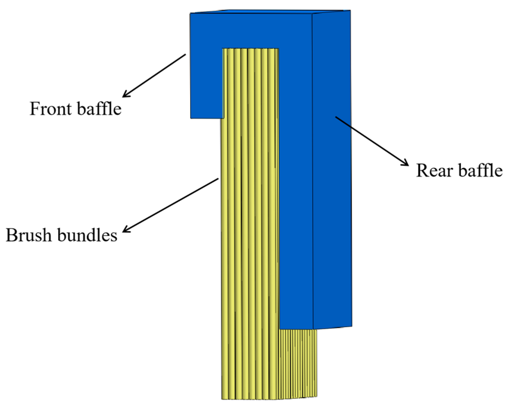
2.1. Brush Seal Construction

A brush seal comprises the front baffle, the brush wire bundle, and the back baffle [18]. A brush seal is a contact seal structure with the end of the brush wire welded between the front and rear baffles. During rotation of the rotor, the brush wire generates a large amount of heat through friction between the brush wire, the rotor, and the air flow, half of which is transferred to the rotor and half of which is transferred to the free end of the brush wire [19]. The working principle of the brush seal is that the brush filament bundle comes into contact with the rotor and forms a sealing structure, using the brush filament bundle area to limit the flow and loss of airflow in the main flow path and preventing backflow and leakage. The basic structure of a brush seal is shown in Figure 1.

2.2. Theoretical Model of Heat Transfer in Porous Media

The internal flow of the filament bundle can be simplified to the internal flow of the porous medium. When using the porous media model to study the heat transfer and leakage characteristics of brush seals, some assumptions need to be made:
(1)
The leakage gas of the brush seal is an ideal compressible gas;
(2)
During the heat flow transfer process of the brush seal, half of the heat is transferred to the rotor, and half of the heat is transferred to the free end of the brush wire;
(3)
The filament material of the brush seal is Haynes25, and the uniform cylinder;
(4)
When modeling the brush filament bundle area of the brush seal, the brush filaments are not drawn, and the entire area is regarded as a porous medium;
Based on the assumptions, the three-dimensional RANS equation of the resistance between the airflow and the brush wire is introduced, that is, by introducing the resistance source term into the RANS equation, including the viscous resistance term and the inertial resistance term [20]:
( ρ u i u j ) x j = p x i + τ i j x j + F i
F i = A i η u i 1 2 B i ρ | u | u i
Equation (1) is the momentum equation, Fi represents the additional resistance source term of the filament bundle to the fluid; Ai and Bi in Equation (2) represent the viscous resistance coefficient and inertial resistance coefficient inside the porous medium of the filament bundle.
Using Ergun’s equation to obtain the flow resistance coefficient in the brush filament bundle:
Δ p L = α μ ( 1 ε ) 2 D p 2 ε 3 v a + β ρ ( 1 ε ) D p ε 3 v a 2
in the formula, α and β are Ergun empirical constants; μ is the dynamic viscosity coefficient; Δp is upstream and downstream pressure difference; L is the distance between upstream and downstream pressure difference; Dp is the average diameter of solid particles in the packed bed, and Dp = 1.5D for the cylindrical brush wire structure; va is the average flow velocity.
The viscous and inertial resistance coefficients for the porous media area of the brush seal were obtained according to [21]:
{ a x = a y = 66.67 ( 1 ε ) 2 D 2 ε 3 a z = 0.4 ε a x b x = b y = 2.33 ( 1 ε ) D ε 3 b z = 0
where the porosity ε is the ratio of the volume of tiny pores in the porous media area to the total volume of the entire porous media area in the brush seal; D is the brush filament diameter; The relationship between the porosity and the radial size of the brush seal filament is derived from the structural parameters of the brush seal [22]:
ε = 1 V S V = 1 π D 2 N D r 8 r ω sin φ
where Vs and V are the brush filament volume and the total volume of the porous media area respectively; N is the brush filament bundle density; Dr is the rotor diameter; r is the radial height of the brush filament; ω is the axial thickness of the brush filament bundle; and φ is the tilt angle of the brush filament bundle.

2.2.1. LTE Model

In the LTE model [23], the bristle bundle region is considered as a whole, and the convective heat transfer between the bristle and fluid within the bristle bundle region is ignored. The fluid and solid temperatures in the region are assumed to be approximately equal. Thus, the convective heat transfer between the brush filaments and the gas in the region is not considered:
t [ ρ f C p f ε + ρ s C p s ( 1 ε ) ] T + ( ρ f C p f u T ) = ( κ e f f T )
where ρf is the fluid density; ρs is the solid skeleton density; Cpf is the constant pressure specific heat capacity of the fluid; and Cps is the constant pressure specific heat capacity of the solid; and κeff is the equivalent thermal conductivity.
Since the direction of heat flow is perpendicular to the direction of the brush filament, the brush filament and the fluid are considered as two thermal resistance values in series, and κeff is calculated as follows [24]:
1 κ e f f = 1 ε κ s + ε κ f
where κf is the thermal conductivity of the fluid and κs is the thermal conductivity of the solid.

2.2.2. The LTNE Model

The LTE model does not consider the convective heat transfer between the brush filament and the fluid in the area of the brush filament bundle. In this paper, the LTNE model is used to analyze the heat transfer and leakage characteristics of the brush seal. The LTNE model therefore adds convective heat transfer between the brush filament and fluid to the LTE model, requiring two energy equations for the fluid and the solid [25]:
{ t ( ρ f C p f ε T f ) + ( ρ f C p f u T f ) = ( κ f T f ) + ρ j κ ( T s T f ) t [ ρ s C p s ( 1 ε ) T s ] = ( κ s T s ) ρ j κ ( T s T f )
where ρj is the interface area density, and κ is the convective heat transfer coefficient between the fluid and the solid surface.
When using the LTNE model, the surface heat transfer coefficient between the brush filament and the airflow needs to be determined. With reference to [26] convective heat transfer coefficients can be determined from the scheinert criterion for a single tube convective heat transfer model:
κ = ( κ f D ) ( 0.3 + 0.62 R e 1 / 2 P r [ 1 + ( 0.4 / P r ) 2 / 3 ] 1 / 4 ) × [ 1 + ( R e 282000 ) 5 / 8 ] 4 / 5
where Re is the Reynolds number of the flow of the fluid involved in the convective heat transfer; and Pr is the Prandtl number of the fluid involved in the convective heat transfer.
The convective heat transfer coefficient in the LTNE model varies with the brush filament and medium temperature, so the convective heat transfer coefficient is actually a mathematical relationship in respect of about temperature. Equation (9) is then programmed into the numerical analysis using UDF to simulate the brush seal convective heat transfer process. As the convective heat transfer coefficient varies in real-time according to the temperature, it is more in line with the actual working conditions.

2.3. Heat Transfer Calculation of Brush Seal and Setting of Brush Material Parameters

In the heat transfer process of brush seals, the heat generated when the brush filament bundle rubs against the rotor can be calculated as follows [27]:
Q h = F f v = ξ F n v = ξ Δ r · ϒ B T P v
where Qh is the heat transferred; Ff is the friction between the brush bundle and the rotor; v is the relative sliding speed of the brush bundle and the rotor; ξ is the friction factor, chosen as 0.3 [28]; Fn is the normal contact force between the brush bundle and the rotor shaft; Δr is the interference between the brush bundle and the rotor shaft; and γBTP is the hardness of the brush bundle, with values ranging from 54.3 to 1085.8 MPa/m [10].
The material used for the bristle wire is Haynes 25, its physical properties are shown in Table 1, and the expression for thermal conductivity with temperature is as follows [29]:
κ s = 3.38 + 0.02 T .
The expression for the change in the specific heat capacity of air with temperature is
C p f = 955.86 + 0.18 T .
The expression for the thermal conductivity of air as a function of temperature is
κ f = 0.0091 + 5.63 × 10 5 T
where the coefficient of viscosity μ at different temperatures is given by the Sutherland formula:
μ = μ 0 ( T T 0 ) 3 / 2 T 0 + T S T + T S
where μ0 is 1.716 × 10⁻⁵ kg/(m.s), TS is 111 K, and T0 is 273 K.
The formulae in this paper provide the numerical basis for analyzing the heat transfer and leakage characteristics of brush seals. The parameters and boundary conditions of the brush seal working conditions were calculated based on the porous media model and input into the finite element analysis calculations as shown in Figure 2.

3. Brush Seal Porous Media Solver Model

3.1. Structure and Boundary Conditions

Here, we use the brush seal structure provided in [30] as the object of study. The working and geometric parameters of the brush seal are shown in Table 2.

3.2. Finite Element Solution Process

The established brush seal structure model was imported into the Fluent module in ANASYS19.2 for numerical calculation. Meshing is performed first, and periodic boundaries are set. Then, the RNG k-ε turbulence model is used to set the parameters of fluid and solid materials, the inlet and outlet pressure and temperature of the calculation model, the rotational speed of the brush wire in contact with the rotor, the porosity and resistance coefficient of the porous media area. Then add the calculated heat flux at the free end of the filament, and then add the UDF of the convective heat transfer coefficient between the filament and the fluid in the porous media LTNE model. The convective heat transfer coefficient is a polynomial with temperature as the independent variable. Therefore, the temperature changes with time, and the convective heat transfer coefficient also changes with the simulation calculation, that is, Formula (9) is introduced into the numerical calculation by the user-defined programming. Finally, the residual parameters and momentum are adjusted to calculate the maximum temperature of the brush wire, the maximum flow rate of the fluid and the leakage rate of the outlet. The flow chart of the finite element analysis is shown in Figure 3.

3.3. Grid-Independent Verification

Before analyzing the heat transfer and leakage characteristics of the brush seal, the mesh irrelevance was verified to determine the appropriate mesh number. Then the computational model of the brush seal was analyzed for different pressure ratios, interference volumes and rotational speeds. The heat transfer and leakage characteristics of the brush seal were analyzed considering a pressure ratio of 6, speed of 12,000 r/min, and interference volume of 0.35 mm based on the porous media model. The maximum brush filament temperature and leakage rate of the brush seal were then determined for seven different grid numbers, when the number of grids is 5 million, the influence of the number of grids on the numerical calculation can be basically excluded, as shown in Figure 4.
Compared to the model in [30], our model has more meshes to divide and more complicated calculations. Thus, a one-sixth circular symmetric structure is used here as the calculation model. Mesh module in Finite element software ANASYS19.2 was used to divide the mesh with a mesh number of 5 million and great mesh quality. Figure 5 provides a map of the calculation area for the simulated brush seal structure, including the fluid inlet area, the outlet area, and the brush filament bundle area using the RNG k-ε turbulent flow model. According to the requirements of the adopted RNG k-ε turbulence model for grids in the near-wall area, the height of the first layer of grids on the wall is set to 0.15 mm, and the corresponding y+ < 5.

3.4. Verification of the Accuracy of the Finite Element Analysis Model

The results for the brush seal calculation model established in this paper were compared and verified with those in [14,24]. The graph shows the increasing trend of leakage calculated in the present study matches well with the experimental values in [14] Further comparison with the values in [24] indicates that the maximum leakage error does not exceed 5%, thus verifying the accuracy of the model, as shown in Figure 6. Errors in the values here are due to the fact that both porous media models are used, and the calculated porosity, inertial resistance coefficients and viscous resistance coefficients are different.

4. Characterization of Brush Seal Flow and Temperature Field Distribution

4.1. Pressure Distribution Characteristics Analysis

At a speed of 12,000 r/min, an interference of 0.35 mm, and an inlet/outlet pressure ratio of 6, the fluid pressure in the upstream area remains essentially unchanged. A fluid pressure drop in the brush bundle area can be seen in Figure 7, thus showing that the brush bundle can play a role in sealing the fluid.

4.2. Characterization of the Velocity Distribution

With a brush seal speed of 12,000 r/min, an interference of 0.35 mm, and a pressure ratio of 6, the fluid flows from upstream to downstream of the brush filament bundle. The flow velocity starts to increase in the brush filament bundle area near the back baffle. Due to the pressure drop, the fluid velocity reaches its maximum at the underside of the back baffle and is higher near the rotor face, flowing out as a jet (see Figure 8).

4.3. Characterization of the Temperature Distribution

At a speed of 12,000 r/min, an interference of 0.35 mm, and a pressure ratio of 6, the temperature in the upstream area is basically constant, with the highest temperature of the brush seal concentrated in the area of contact between the brush filament bundle and the rotor face. At the free end of the brush filament bundle, heat is generated due to friction between the brush filament and the rotor shaft. Then, half of the heat is transferred to the rotor and half is transferred to the brush filament. The highest temperature is located at the free end of the brush bundle where the fluid flows through the area of the bundle, and convective heat transfer takes place between the fluid and the bristles, thereby increasing the fluid temperature as shown in Figure 9.

5. Comparative Analysis of the Factors Influencing the Heat Transfer and Leakage Characteristics of Brush Seals

5.1. Comparative Analysis of Factors Influencing Heat Transfer Characteristics

Figure 10 shows a dotted line graph of the maximum temperature of the brush seal filaments as a function of different pressure ratios, level of interference and increase in speed. The maximum brush filament temperature increases with an increase in the pressure ratio and levels off when the rotational speed, and the interference amount are constant. Compared to the LTE model, the LTNE model has a higher maximum brush filament temperature and its maximum temperature decreases more rapidly with an increase in the pressure ratio, as shown in Figure 10a. For a given pressure ratio and speed, the maximum brush filament temperature increases with the amount of interference, and the temperature gradient becomes larger. The maximum temperature of the brush wire in the LTNE model is higher than that in LTE model, and the temperature gradient also increases more quickly than that in the LTE model, as shown in Figure 10b. The maximum temperature of the brush filament increases with an increase in speed for a given pressure ratio and amount of interference. Compared to the LTE model, the maximum brush filament temperature is higher in the LTNE model and the temperature rises faster, as shown in Figure 10c. The maximum temperature of the brush filament increases with the pressure ratio, amount of interference, and speed of rotation, as shown in Figure 10. Moreover, the temperature increase gradient is higher than that of the LTE model, but the maximum temperature difference does not exceed 3.1%. Since the LTNE model considers convective heat transfer between the brush filament and the fluid, the heat flux is loaded on the free end of the brush filament. The LTE model, however, loads the heat flux over the entire contact surface of the porous media area with the rotor, with some of the heat being partitioned by the fluid at the free end of the brush filament. Therefore, the maximum brush filament temperature in the LTNE model will be higher than that in the LTE model.

5.2. Comparative Analysis of the Factors Influencing Flow Characteristics

Figure 11 shows a dotted line diagram of the fluid flow rate in a brush seal as a function of different pressure ratios, interference volumes, and speed increases. When the rotational speed and amount of interference are certain, the fluid flow velocity increases with an increase in the pressure ratio, but the flow velocity gradient has a tendency to decrease. Comparing the two models, it can be seen that the flow velocity of the LTNE model is consistently greater than that of the LTE model, as shown in Figure 11a. When the pressure ratio and rotational speed are certain, the flow velocity increases with the amount of interference. Moreover, the flow velocity of the LTNE model is larger than that of the LTE model, and the differences between the values of flow velocity under the two models become increasingly smaller, as shown in Figure 11b. When the pressure ratio and amount of interference are fixed, the flow velocity increases with an increase in speed. Additionally, the flow velocity of the two models increases almost linearly, and the flow velocity of the LTNE model is higher than that of the LTE model, as shown in Figure 11c. The LTNE model has a higher flow rate than the LTE model but not significantly so, and the flow rate difference does not exceed 3.4%. As the LTNE model separates the bristles from the fluid, the fluid flow in the porous media region is taken into account. The LTE model does not take into account the fluid flow in the porous media area. Therefore, the LTNE model is more accurate, and the fluid velocities are higher for the same conditions.

5.3. Comparative Analysis of Factors Influencing Leakage Rates

Figure 12 shows a dotted line plot for the leakage rate of the brush seal with different pressure ratios, amounts of interference, and speed increases. When the speed and the amount of interference are constant, the leakage rate increases with an increase in the pressure ratio. Additionally, the leakage rate of the LTE model is greater than that of the LTNE model, as shown in Figure 12a. When the pressure ratio and rotational speed are constant, the leakage rate decreases with an increase in interference, and the gradient of the decrease becomes increasingly larger. Comparing the two models shows that the leakage rate of the LTNE model is lower than that of the LTE model, and the decreasing trend is also faster than that of the LTE model, as shown in Figure 12b. The leakage rate decreases with an increase in speed for a certain pressure ratio and interference amount. The leakage rate decreases almost linearly with speed in both models, but the leakage rate decreases faster for the LTNE model, as shown in Figure 12c. The leakage rate increases with an increase in the pressure ratio and decreases with an increase in interference and rotational speed. As shown in Figure 12, the leakage rate under the LTNE model is lower than that under the LTE model, and the leakage rates differ by no more than 9.0%. The calculations are also more accurate, as finite element analysis of the LTNE model is more complex. Therefore, the sealing effect is better when using the LTNE model.

6. Conclusions

In this paper, we developed a finite element solution for brush seals based on the LTNE and LTE models of porous media and carried out a comparative analysis of the influence of heat transfer and leakage characteristics of brush seals under the two models. The main conclusions are as follows:
  • The fluid reached its maximum velocity below the rear baffle and reached its maximum velocity near the rotor surface, flowing out in a jet; the temperature at the free end of the brush filament was then at its maximum and transferred heat to the root of the filament, where it gradually decreased.
  • The maximum temperature of the brush filament increased with an increase in the pressure ratio, interference volume, and rotational speed. As the pressure ratio increased, the flow velocity increased, which accelerated the convective heat transfer between the brush filament and the airflow. Thus, the temperature increased with the pressure ratio, but the gradient of the increase became increasingly smaller. When comparing the maximum brush filament temperatures in the two models, the maximum brush filament temperature in the LTNE model was higher than that in the LTE model, and the maximum brush filament temperature in the LTNE model varied more significantly.
  • The fluid flow velocity increased with an increase in the pressure ratio, interference volume, and rotational speed. The factors that influenced how fast the fluid flow velocity increased from large to small were: interference volume, rotational speed, and pressure ratio. However, the fluid velocity in the LTNE model always remained slightly higher than that in the LTE model.
  • The leakage rate increased linearly with an increase in the pressure ratio. Additionally, the leakage rate decreased with an increase in interference under an increasing gradient. The leakage rate also decreased linearly with an increase in speed. Overall, the leakage rate values under the LTNE model were significantly lower than those under the LTE model, making the LTNE model preferable in this regard.
  • The LTNE model had a higher temperature and fluid flow rate than the LTE model. Moreover, the LTNE model offered a lower leakage rate than the LTE model. The numerical calculations under the LTNE model were also better than those under the LTE model. Therefore, the numerical calculation under the LTNE model is better than that of the LTE model.
  • On the whole, when using the porous medium model to analyze the sealing performance of the brush seal in the future, the numerical calculation will be more accurate and more in line with the actual working conditions by using the LTNE model.

Author Contributions

Conceptualization, M.L. and J.Z.; methodology, J.Z.; software, J.Z.; formal analysis, J.Z.; writing—original draft, J.Z.; writing—review and editing, M.L., J.Z. and N.P.; language revision and polishing, J.Z.; data curation and visualization, J.Z.; supervision, M.L., J.Z. and N.P.; funding acquisition, M.L. All authors have read and agreed to the published version of the manuscript.

Funding

This work was supported in part by the National Natural Science Foundation of China. The subject project is the establishment of the fluid-solid-thermal coupling model of the brush seal and the dynamic research of the sealing system. Grant No. 51765024.

Institutional Review Board Statement

Not applicable.

Informed Consent Statement

Not applicable.

Data Availability Statement

Not applicable.

Acknowledgments

The authors thank the editors and reviewers for their comments and help. All the authors agree to submit this study for publication.

Conflicts of Interest

The authors declare no conflict of interest.

Nomenclature

FiAdditional drag source term
AiViscous drag coefficient
BiInertia drag coefficient
ΔpDifferential pressure
LUpstream and downstream distance
DpAverage diameter of solid particles
DFilament diameter
vaAverage velocity
VsFilament volume
VTotal volume of porous media region
NTow Density
DrRotor diameter
rRadial height of filament
TTemperature
CpfFluid constant pressure specific heat capacity
CpsSolid constant pressure specific heat capacity
TsSolid temperature
TfFluid temperature
ReReynolds number
PrPrandtl number
FfFriction between filament bundle and rotor
vRelative sliding speed of the filament bundle to the rotor
FnThe normal contact force between the filament bundle and the rotor
ΔrThe amount of interference between the filament bundle and the rotor
T0Normal temperature
TSSutherland constant
Greek Symbols
ρDensity
μDynamic viscosity
εPorosity
ωAxial thickness of filament bundle
φTow angle of inclination
ρfFluid density
ρsSolid density
κeffEquivalent thermal conductivity
κfThermal conductivity of fluid
κsThermal conductivity of solid
ρjInterfacial area density
κConvective heat transfer coefficient between fluid and solid surface
ξFriction factor
γBTPTow hardness
Abbreviations
LTNELocal temperature non-equilibrium
LTELocal temperature equilibrium
FVMFinite volume method
UDFUser-defined function
RANSReynolds-averaged Navier-Stokes
CFDComputational fluid dynamics
RNGRenormalization Group

References

  1. Zhao, H.; Jiao, Z.; Sun, D.; Liu, Y.; Zhan, P.; Xin, Q. Numerical and experimental study on the influencing factors of pressure drop distribution between stages of multi-stage brush seals. J. Acta Aeronaut. Astronaut. Sin. 2020, 41, 74–86. [Google Scholar]
  2. Zhang, Y.; Jun, L.I.; Zhigang, L.I.; Xin, Y.A. Effect of bristle pack position on the rotordynamic characteristics of brush-labyrinth seals at various operating conditions. J. Chin. J. Aeronaut. 2020, 33, 1192–1205. [Google Scholar] [CrossRef]
  3. Lee, K.; Ha, T. Analysis of hybrid brush seal rotordynamic coefficients according to position of brush and clearance using 3D CFD. J. Int. J. Fluid Mach. Syst. 2020, 13, 90–102. [Google Scholar] [CrossRef]
  4. Wei, Y.; Liu, S. Numerical analysis of the dynamic behavior of a rotor-bearing-brush seal system with bristle interference. J. Mech. Sci. Technol. 2019, 33, 3895–3903. [Google Scholar] [CrossRef]
  5. Li, J.; Li, Z.; Zhang, Y.; Wang, L.; Liu, L. Research progress of brush seal technology. J. Aeroengine 2019, 45, 78–88. [Google Scholar]
  6. Fu, T. Research on Thermal Fluid Brush Seal at Rudder Shaft of Aircraft. Master’s Thesis, Beijing University of Chemical Technology, Beijing, China, 2015. [Google Scholar]
  7. Kirk, T.; Bowsher, A.; Crudgington, P. High Temperature Brush Seal Development. In Turbo Expo: Power for Land, Sea, and Air; ASME: New York, NY, USA, 2017; Volume 50886. [Google Scholar]
  8. Chew, J.W.; Hogg, S.I. Porosity Modeling of Brush Seals. J. Tribol. 1997, 119, 769–775. [Google Scholar] [CrossRef]
  9. Qiu, B.; Li, J. Numerical Investigations on the Heat Transfer Behavior of Brush Seals Using Combined Computational Fluid Dynamics and Finite Element Method. J. Heat Transf. 2013, 135, 122601. [Google Scholar] [CrossRef]
  10. Dogu, Y.; Aksit, M.F. Brush Seal Temperature Distribution Analysis. J. Eng. Gas Turbines Power 2005, 128, 599–609. [Google Scholar] [CrossRef]
  11. Chai, B.; Fu, X. Numerical simulation of the flow and temperature fields of brush seals. Lubr. Eng. 2016, 41, 121–125. [Google Scholar]
  12. Qiu, B.; Li, J.; Feng, Z. Investigation of Conjugate Heat Transfer in Brush Seals Using Porous Media Approach Under Local Thermal Non-Equilibrium Conditions. In Turbo Expo: Power for Land, Sea, and Air; ASME: New York, NY, USA, 2015; Volume 56734. [Google Scholar]
  13. Zhang, Y.; Wang, Y.; Yan, X.; Li, J. Study on the leakage flow and heat transfer characteristics of brush seals Part II: Heat transfer characteristics. J. Eng. Thermophys. 2018, 39, 970–976. [Google Scholar]
  14. Bayley, F.J.; Long, C.A. A Combined Experimental and Theoretical Study of Flow and Pressure Distributions in a Brush Seal. J. Eng. Gas Turbines Power 1993, 115, 404–410. [Google Scholar] [CrossRef]
  15. Dogu, Y.; Aksit, M.F.; Demiroglu, M.; Dinc, O.S. Evaluation of Flow Behavior for Clearance Brush Seals. J. Eng. Gas Turbines Power 2008, 130, 012507. [Google Scholar] [CrossRef]
  16. Li, P.; Hu, Y.; Ji, H. Study on the leakage characteristics and hysteresis effect of low hysteresis brush seals. Lubr. Eng. 2020, 45, 52–58. [Google Scholar]
  17. Liu, L.; Zhang, Y.; Li, J. Study on the effect of brush seal on the aerodynamic performance of turbine stage. J. Eng. Thermophys. 2020, 41, 122–127. [Google Scholar]
  18. Chang, Y.; Sun, B.; Zhang, L. Leakage performance predictions of a brush seal based on fluid--solid coupling method. J. Sci. Prog. 2020, 103, 399502459. [Google Scholar]
  19. Zhang, Y.; Yan, J.; Li, J. Numerical study of the factors influencing the leakage and heat transfer characteristics of brush seals. J. Propuls. Technol. 2018, 39, 116–124. [Google Scholar]
  20. Ma, D.; Zhang, Y.; Li, J.; Yan, X. Research on the influence of the rear splint structure considering the deformation of the brush wire on the leakage and heat transfer characteristics of the brush seal. J. Xi’an Jiaotong Univ. 2019, 53, 15–25. [Google Scholar]
  21. Li, H.; Sun, D.; Zhao, H. Numerical method for heat transfer characteristics of brush seal flow. J. Aerosp. Power 2021, 36, 1826–1838. [Google Scholar]
  22. Zhang, Y.; Li, J.; Li, Z.; Yan, X. Numerical comparison of leakage flow and rotordynamic characteristics for two types of labyrinth seals with baffles. J. Eng. Gas Turbines Power 2020, 142, 091008. [Google Scholar] [CrossRef]
  23. Hildebrandt, M.; Schwitzke, C.; Bauer, H. Analysis of heat flux distribution during brush seal rubbing using CFD with porous media approach. J. Energ. 2021, 14, 1888. [Google Scholar] [CrossRef]
  24. Qiu, B.; Li, J. Coupled heat transfer characteristics of brush seal based on local non-thermal equilibrium method for porous media. J. Aerosp. Power 2015, 30, 1067–1075. [Google Scholar]
  25. Lu, L.; Xin, C.; Liu, Z. A review of research on local non-thermal equilibrium models for porous media. Therm. Power Eng. 2019, 34, 1–8. [Google Scholar]
  26. Guo, Z. Study on the Thermal Characteristics of Fluid Dynamic Pressure Fingertip Seal Based on Experimental Environment. Master’s Thesis, Xi’an University of Technology, Xi’an, China, 2020. [Google Scholar]
  27. Zhang, G.; Sun, D.; Jiao, Z. Numerical and experimental study of heat transfer characteristics of two-stage brush seal flow. Chin. J. Turbomach. 2020, 62, 47–55. [Google Scholar]
  28. Zhao, R. Calculation method of carbon fiber brush seal performance and research on leakage characteristics. Mechanical Design and Theory. Master’s Thesis, Xi’an University of Technology, Xi’an, China, 2019. [Google Scholar]
  29. Zhang, S. Performance Study of “L” Shaped Flexible Wire Brush Type Seal. Mechanical Engineering. Master’s Thesis, Beijing University of Chemical Technology, Beijing, China, 2019. [Google Scholar]
  30. Sun, D.; Li, G.; Ai, Y. Numerical study on heat transfer mechanism of brush seal based on 3D solid modeling. J. Aerosp. Power 2019, 34, 1633–1643. [Google Scholar]
Figure 1. Schematic diagram of the basic structure of a brush seal.
Machines 10 00823 g001
Figure 2. Flow chart of formula calculation.
Machines 10 00823 g002
Figure 3. Flow chart of finite element analysis.
Machines 10 00823 g003
Figure 4. Calculation results for different number of grids.
Machines 10 00823 g004
Figure 5. Numerical calculation model of the brush seal.
Machines 10 00823 g005
Figure 6. Leakage rate of brush seal numerical calculation comparison [14,24].
Machines 10 00823 g006
Figure 7. Fluid pressure distribution.
Machines 10 00823 g007
Figure 8. Fluid speed distribution.
Machines 10 00823 g008
Figure 9. Temperature distribution of bristles.
Machines 10 00823 g009
Figure 10. Variation of the maximum brush filament temperature with pressure ratio (a), interference amount (b), and rotational speed (c).
Machines 10 00823 g010
Figure 11. Variation of the fluid flow rate with with pressure ratio (a), interference amount (b), and rotational speed (c).
Machines 10 00823 g011
Figure 12. Variation of the leakage rate with pressure ratio (a), interference amount (b), and rotational speed (c).
Machines 10 00823 g012
Table 1. Physical properties of brush filament materials.
Physical Property ParametersUnitNumerical Values
Densitykg/m39130
Poisson’s ratio 0.29
Elastic Modulus (20 °C~300 °C)GPa231~214
Specific heat capacityJ/(kg°C)385
Thermal conductivity (20 °C~300 °C)w/(m°C)8.27~13.4
Table 2. Brush seal working parameters and geometric parameters.
Parameters/NameUnitNumerical Values
Inlet pressureMPa0.2 to 0.6
Outlet pressureMPa0.1
Inlet temperatureK293
Outlet temperatureK300
Brush wire stiffnessMPa/m271.45 to 1085.79
Amount of interferencemm0.2 to 0.35
Rotational speedr/min1200 to 12,000
Rotor diameter/Dmm129.5
Brush wire diameter/dmm0.102
Bristle bundle thickness/ωmm2.033
Width of backsplash/Lmm2.033
Height of backsplash/H mm2.1
Brush filament inclination angle/Φ°45
Publisher’s Note: MDPI stays neutral with regard to jurisdictional claims in published maps and institutional affiliations.

