Article

Analysis of Synchronous Generator Self-Excitation under Capacitive Load Condition in Variable-Frequency Aviation Power System

1
College of Automation Engineering, Nanjing University of Aeronautics and Astronautics, Nanjing 210016, China
2
AVIC Shenyang Aircraft Design and Research Institute, Shenyang 110035, China
3
School of Automation Science and Electrical Engineering, Beihang University, Beijing 100191, China
4
Beihang School, Beihang University, Beijing 100191, China
*
Author to whom correspondence should be addressed.
Machines 2023, 11(1), 15; https://doi.org/10.3390/machines11010015
Submission received: 10 November 2022 / Revised: 20 December 2022 / Accepted: 20 December 2022 / Published: 23 December 2022
(This article belongs to the Section Electromechanical Energy Conversion Systems)

Abstract

:

Featured Application

This research will be useful for load configuration design in the case of variable-frequency aviation power systems with a reduced risk of synchronous generator self-excitation under capacitive load conditions.

Abstract

As power electronic converters become more widely used in aviation power systems, the associated capacitive loads in the harmonic filter circuits increase accordingly. The risk of self-excitation of aeronautical synchronous generators due to capacitive loads is thus increased. Compared with the self-excitation of a generator in a conventional fixed-frequency power system, this process is more complicated in a variable-frequency aviation power supply (360–800 Hz), as both the varied frequency and the loading conditions contribute to the self-excitation. To quantify this effect, in our study, a series-parallel model of simplified RLC loads under a variable-frequency power supply was built. The criterion of generator self-excitation, given in terms of the generator impedance and the load impedance, was then derived. To facilitate the load configuration design in the case of an aviation power system, a comprehensive analysis of the influences of the varied load power and system frequency on the load impedance was conducted. A graphical approach was proposed to determine self-excitation by comparing the series load reactance and resistor with three critical impedances corresponding to three self-excitation criteria, which is more intuitive and enables one to visualize the tendency of self-excitation with varied frequencies and loading conditions more effectively. Finally, the influence of variable frequency on the self-excitation of the aeronautical synchronous generator was verified by the simulation results.

1. Introduction

Recent decades have witnessed the trend of aviation electrification, led by the concept of more electric aircraft (MEA) and all electric aircraft, with traditional hydraulic and pneumatic energy replaced by more electrical energy in airplanes [1]. This has resulted in significant growth in the number of motor and power electronic devices in aircraft power systems, which exhibit nonlinear load characteristics and adversely affect power quality [2]. To address this issue, filters with capacitors are commonly used, leading to an increase in the capacitive loads. Nonetheless, capacitive loads also lead to certain stability issues, such as resonance with other inductive devices [3]. According to the principle of synchronous generators, capacitive loads may result in the hazardous self-excitation phenomenon, malfunction of the voltage regulators, and even the collapse of the entire system.
The self-excitation of synchronous generators has been extensively studied in the context of utility AC power systems with a nominal frequency of 50 or 60 Hz [4,5,6,7,8]. The main research methods include the state variable approach and phasor analysis approach. As previously reported, the major culprits in causing the self-excitation of synchronous generators include the saliency of the generator rotor, long transmission line, capacitive loads, and filters. However, as the frequency of the utility grid is fixed at around 50 or 60 Hz, the relevant conclusions cannot be directly applied to aircraft AC power systems, partly due to the difference in the grid frequency. Generally, higher frequencies are adopted to reduce the volume and weight of the transformers and inductors in aircraft. Two schemes of grid frequencies exist in AC aviation power systems, of which one is constant frequency (or “CF”, in brief) at 400 Hz, such as that used in the Boeing 767 and Boeing 777 [9,10], and the other is variable frequency (or “VF”), ranging from 360 to 800 Hz, such as that used in the Boeing 787 and Airbus A380 [11,12]. Currently, the VF scheme is gaining dominance due to its advantages of a reduced weight, higher reliability, and adaptability to variable-speed motors.
Until now, the self-excitation of synchronous generators under a VF power supply has not been fully investigated. As an isolated power system, the traditional loads in aircraft are mainly inductive and exhibit a lagging power factor. With the greater uptake of capacitive loads in aircraft power systems, the grid characteristics will undergo essential changes. Among these, the induced self-excitation of synchronous generators is one of the difficult issues, causing voltage instability and reduced safety and reliability. As is well-known, self-excitation may result in abrupt over-voltage and over-current in the generator stator and power system network, drive the field-winding current to become negative, whereupon the excitation system will normally cease to function, and even cause overall system failure and the reduced reliability performance of the aviation power supply [13].
Given the significance of functional reliability in complex systems such as aircrafts, it is worth conducting a thorough analysis to assess the self-excitation process of synchronous generators under VF power supply and capacitive load conditions [14]. In [15], the power factor of VF power systems was analyzed by deriving the impedance characteristics of the inductive filter and capacitive loads with varying grid frequencies. The same authors studied the load characteristics of an asynchronous motor with a terminal capacitor [16]. The self-excitation criterion of a synchronous generator feeding capacitive loads under 115 V/400 Hz grid conditions was studied in [17]. A simplified generator–load model was developed, while the stability criterion was provided from the perspective of the load impedance, load capacity, and power factor. However, the influence of variable frequency was not considered [18].
With the nonlinear characteristics of load impedance under a varied frequency of 360–800 Hz, the self-excitation of a synchronous generator will be more complex than that of its fixed-frequency counterpart. To address this issue, here, the impacts of frequency and load variation on the load impedance are studied. A graphical tool applied to the frequency domain, similar to the bode plots used in stability analysis, is proposed, whereby the criterion of self-excitation is reformulated as the equivalent series load impedance, compared with three critical impedances that are determined by the generator parameters. The mechanism through which a reduced active power load or increased capacitive load leads to self-excitation is revealed by observing the intersection of the relevant impedance curves as the power and frequency change. This research will provide a reference for power supply compliance in variable-frequency aviation power systems.

2. Capacitive Loads and Self-Excitation of Aviation Synchronous Generators

The traditional three-stage aero-synchronous generator in a three-phase, four-wire system is considered, with the main generator being electrically excited and possessing a salient rotor.

2.1. Simplified Model of Generator–Load System

For simplicity, the per-phase model of an aero-generator serving parallel RLC loads was developed, as shown in Figure 1a, where RL, XL, and XC denote the resistive load, inductive load, and capacitive load, respectively. The synchronous generator is characterized by a steady-state phase voltage ea, inner resistance ra, and inductance Xa. The parallel load is transformed to the equivalent series load, as shown in Figure 1b. The relationship between RL, XL, XC, and the series resistance RLS, inductance XLS, and capacitance XCS are given by (1), where |ZL| is the magnitude of the load impedance:
{ R L S = | Z L | 2 / R L X L S = | Z L | 2 / X L X C S = | Z L | 2 / X C , | Z L | 2 = ( R L X L X C ) 2 ( X L X C ) 2 + R L 2 ( X L X C ) 2
In Figure 1b, the sum of the inductance and capacitance on the load side is given by (2), corresponding to the net reactive power:
X Z S = X C S X L S = | Z L | 2 X L X C X C X L
Based on the two-reaction theory, the voltage equation of the generator–load system in the dq reference frame is given by (3), where vd, vq, and vF denote the voltage in the d-axis, q-axis, and field winding; id, iq, and iF denote the current in the d-axis, q-axis, and field winding; and Xmd is the mutual inductance between the field winding and the virtual d-axis winding [19,20].
[ v d v q v F ] = [ r a + R L S X q X Z S X m d X d + X Z S r a + R L S 0 X m d 0 R F ] [ i d i q i F ]

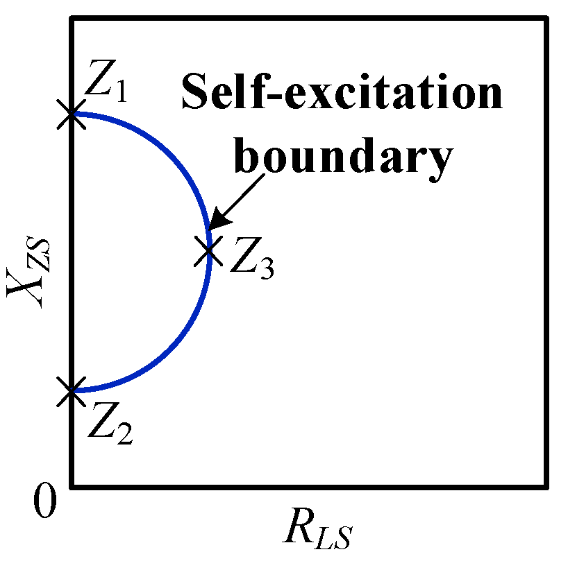
2.2. Criterion of Synchronous Generator Self-Excitation

The voltage–current relationship (3) can be represented by the phasor diagram in Figure 2. When the load is inductive, the current phasor will lag behind the voltage phasor. In this case, id is oppositive to iF; thus, the armature reaction will have a demagnetizing effect. When the load is capacitive, the current phasor will lead ahead of the voltage phasor. id aligns with iF, indicating a magnetizing effect of the armature reaction.
As observed, if id is too large in the capacitive load condition, it will establish the main magnetic flux instead of iF. The synchronous generator will then enter the self-excitation state, which indicates that self-excitation will occur when the excitation current is negative. Based on [21], if the salient-pole synchronous generator is not self-excited, its reactance XZS and resistance RZS should meet condition (4), whose solution is given by (5):
( X Z S X d + X q 2 ) 2 + ( r a + R L S ) 2 > ( X d X q 2 ) 2
{ X Z S > X d + X q ( X d X q ) 2 4 ( r a + R L S ) 2 2 X Z S < X d + X q + ( X d X q ) 2 4 ( r a + R L S ) 2 2

2.3. The Loading Condition of Self-Excitation

Clearly, the self-excitation condition of a synchronous generator, based on (5), is not so comprehensible, partly due to its square root formulation. The region of the series load impedance RLS and XZS for self-excitation is depicted in Figure 3, beyond which the synchronous generator will be self-excited.
In the boundary of the half circle, three critical points, Z1, Z2, and Z3, are found, which constitute the sufficient but not necessary conditions for self-excitation, as shown in (6), among which if one is satisfied, then it will be safe.
Z 1 : X Z S > X d Z 2 : X Z S < X q Z 3 : R L S > 1 2 ( X d X q ) r a }

3. The Variable Frequency Characteristics of the Load Impedance

When the grid frequency is variable, the impedance of a synchronous generator and the load as well as the region of the synchronous generator self-excitation will be affected.

3.1. Impact of Variable Frequency on the Load Impedance

The inductive or capacitive loads change as the power supply frequency varies. The normal voltage of the power supply is 115 V, and the frequency ranges from fmin = 360 Hz to fmax = 800 Hz, with ω = 2πf. For convenience, here, a frequency of 400 Hz is selected as the base value.
The value of the paralleled impedance for a random frequency ω is quantified by (7):
{ X C ( ω ) = 1 / ( ω C P ) X L ( ω ) = ω L P
As seen above, both XZS and RLS exhibit nonlinear characteristics with a varied frequency. Assuming resistive, inductive, and capacitive loads of 4 kW, 3 kVA (400 Hz), and 5 kVA (400 Hz), the impedance characteristics under a variable frequency are shown in Figure 4.
The load impedance has two obvious features: (1) For f < 400 Hz and XZS < 0, the load is inductive. Specifically, for f = 360 Hz, the power factor is 0.97 lagging. (2) For f > 400 Hz and XZS > 0, the load is capacitive. Specifically, for f = 800 Hz, the power factor is 0.56 leading.

3.2. Admittance Model of the Series Load

In the load configuration design of an aviation power system, such as that shown in Figure 1a, it is necessary to analyze the influences of the resistive, inductive, and capacitive load capacities on the generator’s self-excitation characteristics. In (6), the impedances XZS and RLS are used to determine whether the load is within the self-excitation range of the generator.
Firstly, the formulation of XZS and RLS are derived in terms of the original parallel impedances, RL, XL, and XC. Equation (1), in this case, is simplified as (8), where XZ is the impedance of the total reactive power load in parallel:
{ R L S = R L X Z 2 R L 2 + X Z 2 X Z S = R L 2 X Z R L 2 + X Z 2 ,   X Z = X L X C X L X C
By rewriting the load impedance as the admittance in (9), the relationship between the load capacity and the self-excitation of the generator can be more effectively analyzed. The admittance of the reactive power load in parallel is then obtained as shown in (10):
Y R = 1 / R L Y L = 1 / X L = 1 / ( ω L P ) Y C = 1 / X C = ω C P }
Y Z = 1 X z = Y C Y L = ω C P 1 ω L P = ω 2 L P C P 1 ω L P
Clearly, the load appears to be capacitive if YZ > 0 and inductive if YZ < 0. The impedance of the equivalent series load system, represented by the admittance, is:
X Z S = Y Z Y Z 2 + Y R 2 , R L S = Y R Y Z 2 + Y R 2
Since YZ has better linear frequency characteristics than XZ, it is more suitable for the analysis of the frequency characteristics of XZS and RLS.

3.3. Frequency Characteristics of the Series Load Impedance

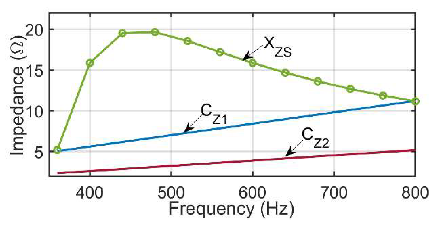
3.3.1. Frequency characteristics of reactance XZS

As seen from Figure 4, there is an extreme point A in the curve of reactance XZS, which satisfies YZ = YR by setting the derivative of XZS as 0 with respect to YZ:
d X Z S d Y Z = Y R 2 Y Z 2 ( Y Z 2 + Y R 2 ) 2 = 0
Furthermore, the values of XZS and RLS on point A can be obtained as:
X Z S A = Y Z Y Z 2 + Y R 2 = 1 2 R L R L S A = Y R Y Z 2 + Y R 2 = 1 2 R L }
According to (10), we have (13), indicating the admittance YZ and frequency ωA at point A:
Y Z ( ω A ) = ω A 2 L P C P 1 ω A L P = Y R = 1 R L
ω A = 1 2 R L C P ( 1 + 1 + 4 R L 2 C P L P )
Note that there may be cases of fA < 360 Hz or fA > 800 Hz when XZS becomes monotonically decreasing or increasing in the full frequency range.

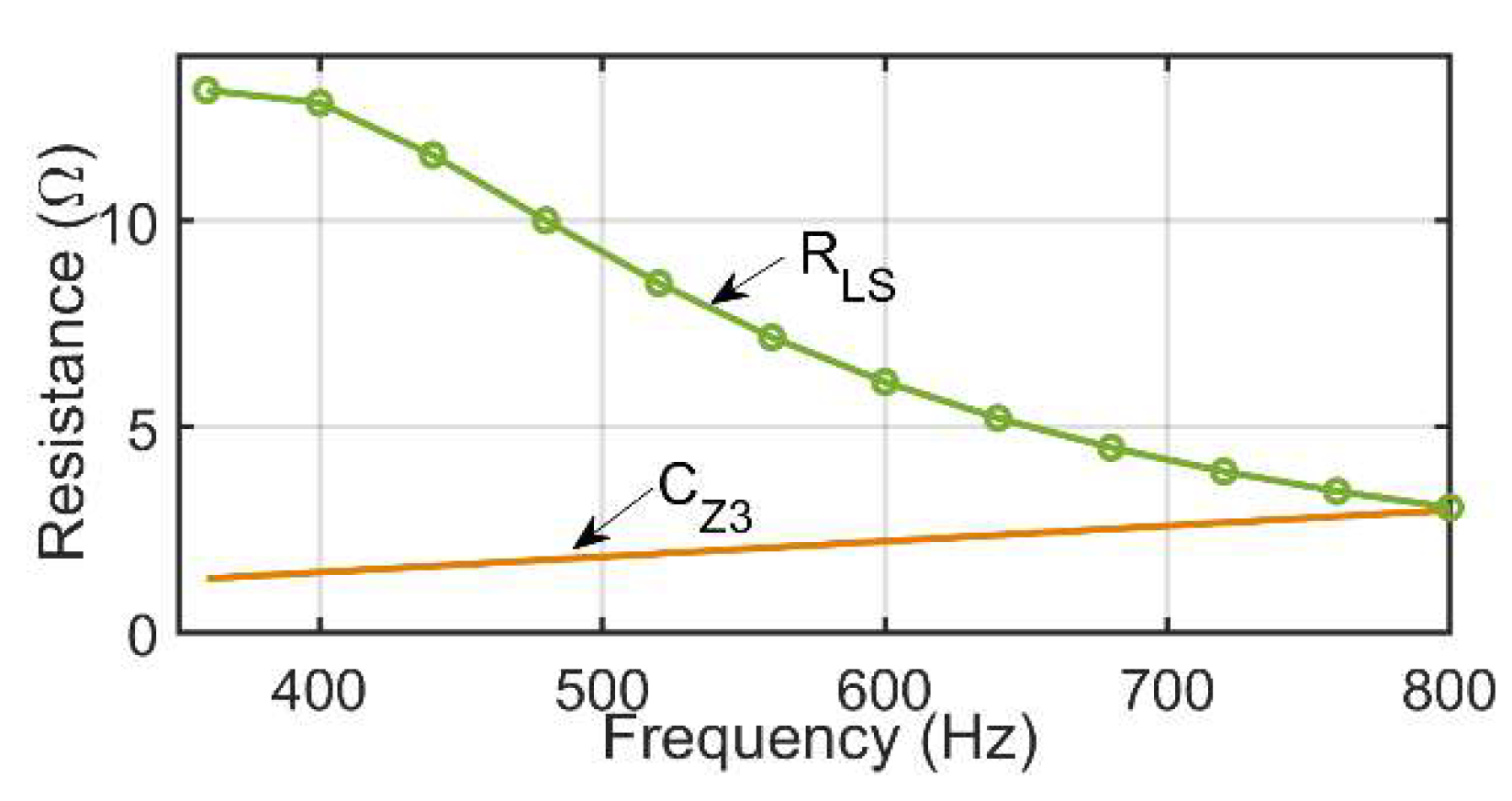
3.3.2. Frequency Characteristics of Resistance RLS

The derivative of RLS with respect to YZ is given by (14), indicating that RLS will increase as the frequency increases for the capacitive load (YZ > 0) and decrease for the inductive load (YZ < 0). When studying the synchronous generator self-excitation characteristics, the capacitive load (YZ > 0) is considered.
d R L S d Y Z = 2 Y R Y Z ( Y Z 2 + Y R 2 ) 2

3.4. The Series Impedance Expressed by the Load Capacity

Assuming a constant voltage magnitude Us, the power capacity is proportional to the load admittance. The active power PZ and reactive power QZ of the load are:
P Z = U s 2 Y R = U s 2 R L Q Z = Q C Q L = U s 2 ( Y C Y L ) = U s 2 Y Z = U s 2 ( ω C p 1 ω L p ) }
The series load impedance in terms of the power capacity is given by (16). The variation in QZ may result from the change in QC or QL, but their effects on RLS and XZS are the same.
X Z S = Q Z U s Q Z 2 + P Z 2 R L S = P Z U s Q Z 2 + P Z 2 }

4. Application of the Self-Excitation Criterion to a VF Generator

When applying criterion (6) to a VF aviation power system, the frequency characteristics of the load impedance and synchronous generator impedance, as analyzed in Section 3, are considered, and detailed below.

4.1. The Threshold of Synchronous Generator Self-Excitation

In the sufficient condition (6) of self-excitation, there are three thresholds determined by the generator parameters, defined in (17):
C Z 1 ( ω ) = X d ( ω ) = L d ω C Z 2 ( ω ) = X q ( ω ) = L d ω C Z 3 ( ω ) = 1 2 [ X d ( ω ) X q ( ω ) ] r a }
As we can see, all the three threshold values increase linearly with the frequency. Among them, CZ1 and CZ2 are related to the reactance XZS, and CZ3 is related to RLS. Without a loss of generality, the data on the synchronous generator in Table 1 were used in our analysis of the self-excitation characteristics.

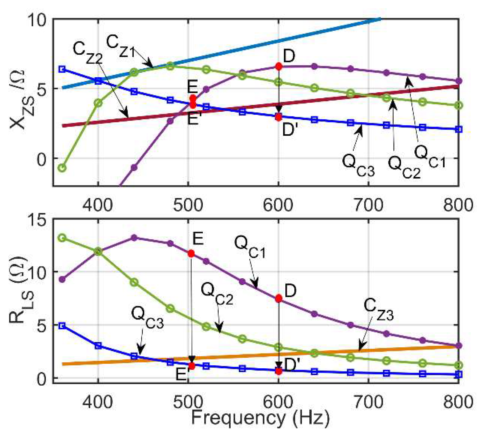
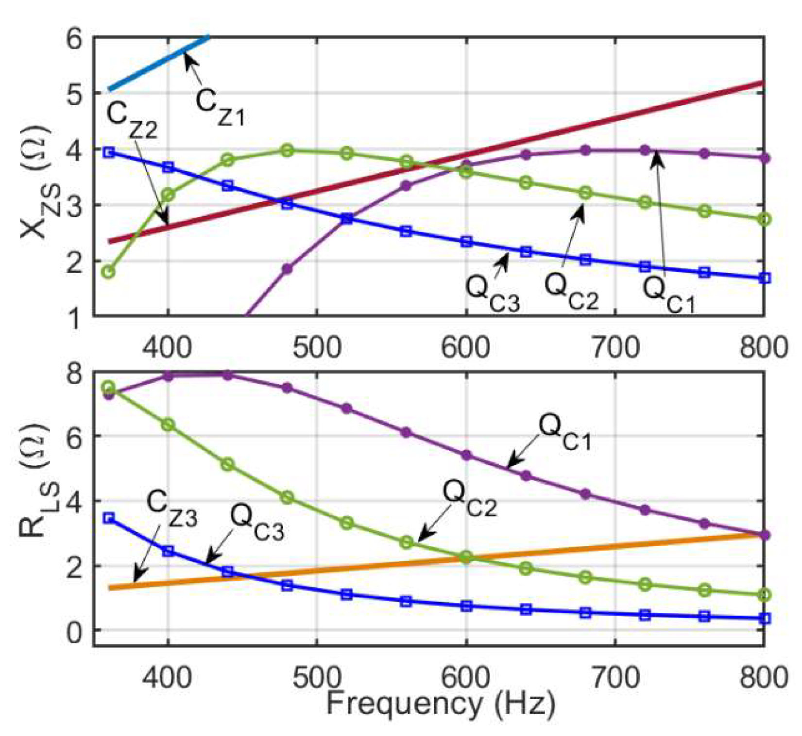
4.2. Individual Criterion for the Self-Excitation of the Synchronous Generator

Any of the sufficient conditions in Equation (6) can be used as an independent criterion. The three load systems in Table 2 were selected for the case studies in our research. The capacities of QL, QC, and QZ are all given at the nominal frequency of 400 Hz.

4.2.1. Application of Criterion Z1

The Z1 criterion requires that XZS satisfy (18) in the considered frequency range of fminfmax:
X Z S ( f ) > C Z 1 ( f ) = 2 π f L d
According to the frequency characteristics of XZS analyzed earlier, the minimum value will appear at the lowest frequency fmin or the highest frequency fmax. Based on the property of the convex function, if the following condition (19) holds, then XZS > CZ1 in the full range from fmin to fmax:
X Z S ( f max ) > C Z 1 ( f max ) X Z S ( f min ) > C Z 1 ( f min ) }
For the generator in Table 1 and the load in Case 1 in Table 2, the frequency characteristics of XZS and threshold values CZ1 and CZ2 are as shown in Figure 5. As we can see, XZS is larger than CZ1 in the full frequency range; thus, the generator will not be self-excited.

4.2.2. Application of Criterion Z2

If the Z2 criterion is used, XZS should meet the requirement of (20) in the full frequency range:
X Z S ( f ) < C Z 2 ( f ) = 2 π L q f
According to the frequency characteristics of XZS analyzed earlier, there are two situations that arise in the application of the Z2 criterion:
(a) If fA < fmin or fA > fmax, XZS monotonically decreases or increases over the whole frequency range, which requires:
X Z S ( f min ) < C Z 2 ( f min ) = 2 π L q f min   or X Z S ( f max ) < C Z 2 ( f max ) = 2 π L q f max ;
and (b) If fmin < fA < fmax, XZS is a convex curve with a maximum value. If the following condition holds, then it can be concluded XZS satisfies the Z2 criterion in the full range:
X Z S ( f A ) < C Z 2 ( f A )
Additionally, using the generator data in Table 1 and the load in Case 2 in Table 2, the frequency characteristics of XZS and the thresholds CZ1 and CZ2 are as shown in Figure 6. As we can see, the maximum point is reached at fA = 640 Hz, where XZS < CZ2. However, at f = 600 Hz, where XZS is closest to CZ2, we must verify whether XZS is in the self-excited safe zone.

4.2.3. Application of Criterion Z3

CZ3 (the threshold of the Z3 criterion) increases with the increase in the power supply frequency. Therefore, if the relation in (21) holds, then the Z3 criterion is satisfied from fmin to fmax, and the generator is in the self-excitation safe zone. For the generator data in Table 1 and the load in Case 3 in Table 2, the frequency characteristics RLS, shown in Equation (13), decrease as the frequency increases. The frequency characteristics of RLS and CZ3 are shown in Figure 7. As we can see, because RLS is greater than CZ3 in the full frequency range, the generator will not be self-excited.
R L S ( f max ) > C Z 3 ( f max )

4.3. “Complementary” Property of the Self-Excitation Criteria

The independent application of the Z1, Z2, or Z3 criterion to determine whether the generator will be self-excited is a “harsh” sufficient condition. According to (13), RLS decreases with the increased grid frequency; thus, the Z3 criterion can be met more easily in low-frequency ranges. If XZS satisfies the Z1 or Z2 criterion in the high-frequency range, then the combination of the Z3 criterion with the Z1 or Z2 criterion will constitute a “complementary” sufficient condition.
For example, if the QC of the capacitive load in Case 2 in Table 2 is increased to 7.5 kVA, i.e., QZ = 2.5 kVA, the series impedance characteristics will be as shown in Figure 8. As we can see, XZS violates the Z2 and Z3 criteria at f < 570 Hz, and RLS violates the Z3 criterion at f > 600 Hz. However, since the two frequency ranges are staggered, there are no intervals that violate all three criteria. Therefore, the generator will not be self-excited over the full frequency range.

5. Impact of the Load Capacity on Generator Self-Excitation

In aviation power systems, countermeasures should be taken to avoid the self-excitation of the generator by adjusting the load capacity. Here, the influence of the load capacity on the self-excitation characteristics is studied by analyzing the relationship between the load capacity and its impedance.

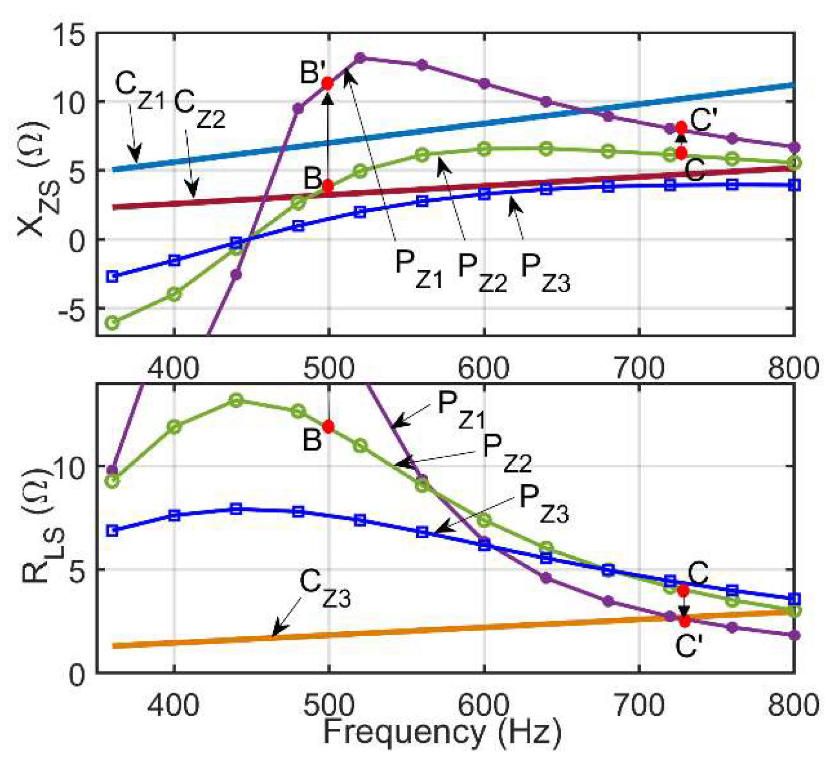
5.1. Impact of Active Power Variation on the Series Load Impedance

5.1.1. Impact of PZ variation on XZS

According to equation (16), when QZ > 0, the increase in PZ will lead to a decrease in XZS, and conversely, the decrease in PZ will lead to an increase in XZS. According to (12), the maximum XZSA is determined by the resistance RL. That is, XZSA is inversely proportional to PZ:
X Z S A = R L 2 = U s 2 2 P Z
For the Case 3 load system shown in Table 2, setting PZ to PZ1 = 1.5 kW, PZ2 = 3 kW, and PZ3 = 5 kW, respectively, the frequency characteristics of XZS and RLS are as shown in Figure 9.
For load PZ1, the XZS curve has a large “peak” at XZSA, and part of the curve is above the threshold CZ1. For load PZ2, the decrease in XZSA causes the XZS curve to become “flatter”, and most of the curve lies between CZ1 and CZ2. For load PZ3, the XZSA is further reduced, so that the XZS curve becomes even “flatter”, and all the curves are below CZ2. The generator is completely within the self-excitation safe zone.

5.1.2. Impact of PZ variation on RLS

Firstly, the derivative of RLS with respect to PZ is obtained as shown in (23). As we can see, RLS will increase as PZ increases for QZ > PZ, and the opposite occurs for QZ < PZ. Since the frequency characteristics of QZ increases under capacitive loading, QZ >PZ is often satisfied in the high-frequency range, and RLS will thus increase as PZ increases. In the low-frequency range, RLS will decrease as PZ increases for QZ < PZ.
R L S P Z = U s ( Q Z 2 P Z 2 ) ( Q Z 2 + P Z 2 ) 2
According to (14), the frequency characteristics of RLS are decreasing. The increase in PZ will reduce the decreasing speed of RLS based on (23) and, thus, increase the value of RLS in the high-frequency range, rendering it easier to meet the Z3 criterion. Conversely, as PZ decreases, the RLS decreasing speed increases, which is not conducive to meeting the Z3 criterion in the high-frequency range.
As shown in the RLS part of Figure 9, for a large PZ, such as PZ2 or PZ3, the decrement rate of RLS in the high-frequency range decreases. Therefore, the value of RLS increases, which satisfies the Z3 criterion. At PZ1, the RLS curve falls too quickly, which violates the Z3 criterion in the high-frequency range. The above analysis shows that PZ affects the “slope” of RLS. As PZ increases, the high-frequency characteristics of RLS are improved, rendering it easier to meet the Z3 criterion.
Combining the observations in Section 5.1.1 and Section 5.1.2, it is found that the active power variation mainly affects the “vertical” characteristics of the impedance curves, similar to the way in which the quality factor defined in the RLC circuit affects the sharpness of the impedance curves. Namely, decreased PZ will result in sharper curves with higher peaks, steeper slopes, and narrower “bandwidths”. Consequently, there is an increased likelihood that XZS and RLS will cross the critical impedances Z1, Z2, and Z3, resulting in a higher probability of generator self-excitation.

5.2. Impact of Reactive Power Variation on the Series Load Impedance

5.2.1. Impact of QZ variation on XZS

According to (12) and (13), the change in the capacitive load CP will affect the extreme point frequency fA on the curve of XZS but will not affect the value of XZSA. As we can see, the increase in QZ (or QC) will shift fA to a lower frequency, and the decrease in QZ will shift fA to a higher frequency. If the QC in Case 3 in Table 2 is changed from QC1 = 4 kVA to QC2 = 6 kVA and QC3 = 10.5 kVA, the frequency characteristics of XZS and RLS will be as shown in Figure 10.
As we can see, part of the XZS curve lies between CZ1 and CZ2. As QC increases, XZS moves to the lower range, rendering XZS smaller than CZ2 in the high range. The interval in which XZS lies lower than CZ2 in the high-frequency range, i.e., the frequency range meeting the Z2 criterion, expands.

5.2.2. Impact of QZ Variation on RLS

According to (16), the reactive power QZ is in the denominator of RLS formulation. Therefore, the increase in QZ will cause RLS to decrease, and vice versa.
As we can see from the RLS part of Figure 10, if QC increases, the intersection of RLS and CZ3 shifts to the lower range, and RLS, in the high-frequency range, no longer satisfies the Z3 criterion due to the decrease in RLS. That is, the frequency range that satisfies the Z3 criterion shrinks.
Based on the observations in Section 5.2.1 and Section 5.2.2, it is found that the reactive power variation mainly affects the “horizontal” characteristics of the impedance curves. Increasing the capacitive load will cause both the reactance and resistance curves to move leftward. The frequency range in which XZS and RLS cross the critical impedances Z1, Z2, and Z3 will expand, resulting in a higher probability of generator self-excitation.

5.3. Impact of QZ Variation on the Complementary Property of the Z2 and Z3 Criteria

For the load system in Case 2 in Table 2, it can be seen in Figure 11 that XZS lies between CZ1 and CZ2. Here, the self-excitation characteristics are analyzed when the XZS curves move horizontally as QC varies (QC1 = 4.5 kVA, QC2 = 7.5 kVA, QC3 = 12.5 kVA).
Compared with Figure 8, it can be seen that as QC increases, the high-frequency range in which XZS satisfies the Z2 criterion expands, while the low-frequency range in which RLS satisfies the Z3 criterion shrinks. The two ranges complement each other to a certain extent.
However, with the capacitive load QC3, XZS satisfies the Z2 criterion in the frequency range of f > 475 Hz, while RLS satisfies the Z3 criterion in the frequency range of f < 450 Hz. In this case, the complementary property of the Z2 and Z3 criteria is lost, and self-excitation may occur in the frequency range of 450 < f < 475 Hz. More generally, when the XZS curve crosses CZ2, the complementary property of the Z2 and Z3 criteria will deteriorate or even disappear with the increase in QC.

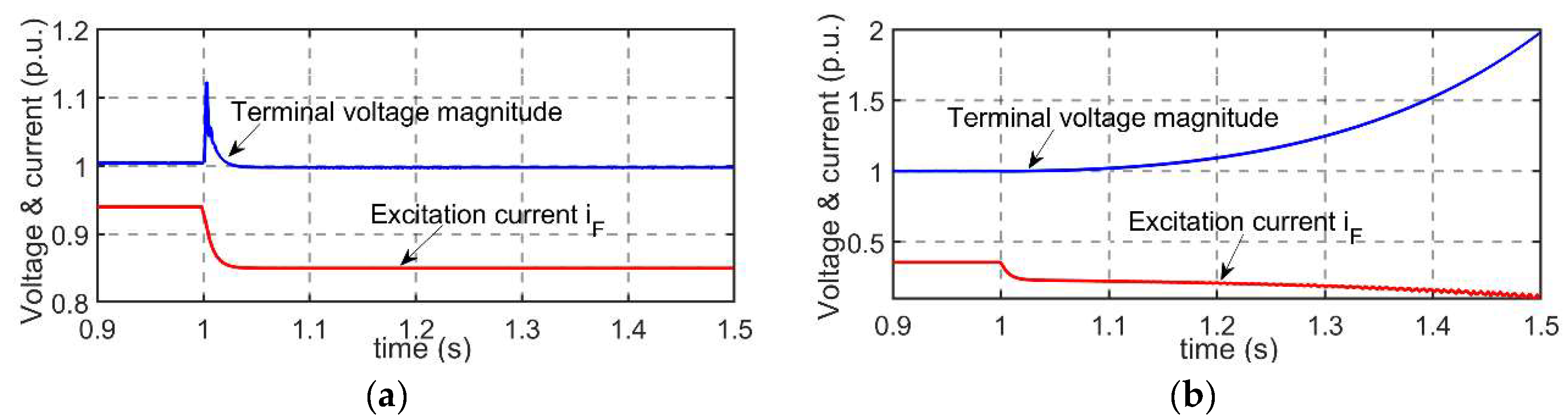
6. Simulation Verification

To verify the relationship of the self-excitation with the loading composition analyzed above, a simulation was conducted based on the aviation generator modeled, as depicted in Table 1. The three-phase synchronous generator provides a 115 V/360–800 Hz power supply, and the load is a variable RLC parallel branch.

6.1. Self-Excitation Characteristics as the Active Power Changes

Here, Case 3 in Table 2 is used as the base loading case. According to the series load characteristics shown in Figure 10, the operation under frequencies of 500 Hz (points B and B′ in Figure 9) and 726 Hz (points C and C′ in Figure 9) is simulated. The resistive load PZ varies from 3 kW to 1.5 kW at 1 s.
The simulation results are shown in Figure 12. At the frequency of 500 Hz, the generator can regulate the voltage normally. However, at the frequency of 726 Hz, the generator is self-excited. The excitation current decreases, and the voltage becomes unstable. This is consistent with the analysis shown in Figure 9.

6.2. Self-Excitation Characteristics as the Reactive Power Changes

Again, using the data for Case 3 in Table 2, the generator’s operation at frequencies of 600 Hz (points D and D′ in Figure 10) and 505 Hz (points E and E′ in Figure 10) is simulated according to the series load characteristics in Figure 10. In the simulation, the capacitive load QC varies to 10.5 kVA at 1 s.
The simulation results are shown in Figure 13. At the frequency of 600 Hz, the generator works normally. However, at the frequency of 505 Hz, the generator is self-excited, the excitation current drops, and the voltage becomes unstable. This result is consistent with the conclusions shown in Figure 10.

7. Conclusions

In this paper, the range of capacitive loads invoking the self-excitation of a synchronous generator was obtained by analyzing the frequency characteristics of the load impedance under variable aviation frequencies (360–800 Hz). The relationship between the power supply frequency, load capacity, and synchronous generator self-excitation was revealed. The key conclusions are summarized below:
(1) The criterion of synchronous generator self-excitation is changed from its original form of square root inequality without explicitly showing frequency into the problem of two parabola curves intersecting with three linear curves corresponding to the three sufficient conditions identified herein. With the frequency as the abscissa and the impedance of the machine side and the load side as the ordinate, the method is intuitive, enabling us to directly observe the trend of the system impedance and generator self-excitation as the supply frequency and load power change.
(2) The change in the active power load mainly affects the peak and slope of the resistance and the reactance curve under a variable-frequency power supply. Increasing the active power load will alleviate the risk of self-excitation of the synchronous generator.
(3) The change in the reactive power load mainly affects the horizontal characteristics of the resistance and reactance curves. Increasing the capacitive load will enlarge the frequency range, violating the self-excitation criterion.
The analysis approach and the findings of this research will be useful for the design of variable-frequency power system in more electric aircraft, especially the configuration of capacitive loads.

Author Contributions

Conceptualization, C.S.; methodology, M.H.; software, H.L.; validation, H.L.; formal analysis, H.L.; data curation, N.W. and C.S.; writing—original draft preparation, H.L., C.S. and Y.Z.; writing—review and editing, all authors; visualization, H.L.; project administration, Y.Z.; funding acquisition, N.W. All authors have read and agreed to the published version of the manuscript.

Funding

This research was funded by the Beijing Institute of Precision Mechatronics and Controls. The project was supported by the School of Automation Science and Electrical Engineering, Beihang University, Beijing, China.

Conflicts of Interest

The authors claim no conflict of interest.

References

  1. Sarlioglu, B.; Morris, C.T. More Electric Aircraft: Review, Challenges, and Opportunities for Commercial Transport Aircraft. IEEE Trans. Transp. Electrif. 2015, 1, 54–64. [Google Scholar] [CrossRef]
  2. Dorn-Gomba, L.; Ramoul, J.; Reimers, J.; Emadi, A. Power Electronic Converters in Electric Aircraft: Current Status, Challenges, and Emerging Technologies. IEEE Trans. Transp. Electrif. 2020, 6, 1648–1664. [Google Scholar] [CrossRef]
  3. Kundur, P.; Paserba, J.; Ajjarapu, V.; Andersson, G.; Bose, A.; Canizares, C.; Hatziargyriou, N.; Hill, D.; Stankovic, A.; Taylor, C.; et al. Definition and Classification of Power System Stability IEEE/CIGRE Joint Task Force on Stability Terms and Definitions. IEEE Trans. Power Syst. 2004, 19, 1387–1401. [Google Scholar] [CrossRef]
  4. Hu, Y.; McLaren, P.; Gole, A.; Fedirchuk, D.; Castro, A. Self-excitation operating constraint for generators connected to DC lines. IEEE Trans. Power Syst. 1999, 14, 1003–1009. [Google Scholar] [CrossRef]
  5. Youfang, X. The Practical Criterion of Generator Self Excitation and its Field Example Analysis. In Proceedings of the 1993 2nd International Conference on Advances in Power System Control, Operation and Management, APSCOM-93, Hong Kong, China, 7–10 December 1993; pp. 321–323. [Google Scholar]
  6. Balasubramanian, R.; Ram, B.; Tripathy, S. Temporary overvoltages due to load rejection on a series-compensated transmission line. IEE Proc. C Gener. Transm. Distrib. 1983, 130, 8–15. [Google Scholar] [CrossRef]
  7. Nikkila, A.-J.; Kuusela, A.; Laasonen, M.; Haarla, L.; Pahkin, A. Self-Excitation of a Synchronous Generator During Power System Restoration. IEEE Trans. Power Syst. 2019, 34, 3902–3911. [Google Scholar] [CrossRef]
  8. Liu, J.; Chen, W.; Jiao, X.; Zheng, T. Research on Self-Excitation Overvoltage of Offshore Interconnected Power System. In Proceedings of the 2021 IEEE 4th Student Conference on Electric Machines and Systems (SCEMS), Huzhou, China, 1–3 December 2021; pp. 1–5. [Google Scholar]
  9. Andrade, L.; Tenning, C. Design of Boeing 777 electric system. IEEE Aerosp. Electron. Syst. Mag. 1992, 7, 4–11. [Google Scholar] [CrossRef]
  10. Eid, A.; El-Kishky, H.; Abdel-Salam, M.; El-Mohandes, T. Constant Frequency Aircraft Electric Power Systems with Harmonic Reduction. In Proceedings of the 2008 34th Annual Conference of IEEE Industrial Electronics, Orlando, FL, USA, 10–13 November 2008; pp. 623–628. [Google Scholar]
  11. Chang, J.; Wang, A. New VF-power system architecture and evaluation for future aircraft. IEEE Trans. Aerosp. Electron. Syst. 2006, 42, 527–539. [Google Scholar] [CrossRef]
  12. Wheeler, P. Technology for the More and All Electric Aircraft of the Future. In Proceedings of the 2016 IEEE International Conference on Automatica (ICA-ACCA), Curico, Chile, 19–21 October 2016; pp. 1–5. [Google Scholar]
  13. Loganathan, M.; Gandhi, M.S.; Gandhi, O. Functional cause analysis of complex manufacturing systems using structure. Proc. Inst. Mech. Eng. Part B J. Eng. Manuf. 2015, 229, 533–545. [Google Scholar] [CrossRef]
  14. Loganathan, M.; Gandhi, O. Reliability enhancement of manufacturing systems through functions. Proc. Inst. Mech. Eng. Part B J. Eng. Manuf. 2017, 231, 1850–1868. [Google Scholar] [CrossRef]
  15. Mengyu, H.; Wang, Z.; Zhou, Y. Self-excitation analysis of aeronautical generator with capacitive load. Control. Theory Appl. 2018, 35, 1133–1141. (In Chinese) [Google Scholar]
  16. He, M.; Zhou, Y. The Analysis of the Power Factor of the Capacitive Pulse Load in the Aviation Variable Frequency Power Supply System. In Proceedings of the 2016 4th International Conference on Advanced Materials and Information Technology Processing (AMITP 2016), Guilin, China, 24–25 September 2016; pp. 40–44. [Google Scholar]
  17. He, M.; Zhou, Y. Study on Load Characteristics of Asynchronous Motor with Capacitor in Aviation Variable Frequency Power Supply System. In Proceedings of the 2017 2nd IEEE International Conference on Recent Trends in Electronics, Information & Communication Technology (RTEICT), Bangalore, India, 19–20 May 2017; pp. 1708–1711. [Google Scholar]
  18. Zhang, Z.; Li, J.; Liu, Y.; Xu, Y.; Yan, Y. Overview and development of variable frequency AC generators for more electric aircraft generation system. Chin. J. Electr. Eng. 2017, 3, 32–40. [Google Scholar]
  19. Maroufian, S.S.; Pillay, P. Self-Excitation Criteria of the Synchronous Reluctance Generator in Stand-Alone Mode of Operation. IEEE Trans. Ind. Appl. 2018, 54, 1245–1253. [Google Scholar] [CrossRef]
  20. Rebahi, F.; Bentounsi, A.; Khelifa, H.; Boulkhrachef, O.; Meherhera, D. Comparative Study of a Self-Excited Induction and Synchronous Reluctance Generators Capabilities. In Proceedings of the 2019 International Conference on Advanced Electrical Engineering (ICAEE), Algiers, Algeria, 19–21 November 2019; pp. 1–5. [Google Scholar]
  21. Gao, J.; Zhang, L.; Wang, X. AC Machine Systems: Mathematical Model and Parameters, Analysis, and System Performance; Springer Science & Business Media: Berlin, Germany, 2009. [Google Scholar]
Figure 1. Simplified generator–load model: (a) parallel load; (b) equivalent series load.
Machines 11 00015 g001
Figure 2. Vector diagram of the generator–load system with: (a) inductive load; (b) capacitive.
Machines 11 00015 g002
Figure 3. The self-excitation range of the series load impedance.
Machines 11 00015 g003
Figure 4. Curve of the load impedance with varied frequency.
Machines 11 00015 g004
Figure 5. Curves of XZS(f) satisfying the Z1 criterion.
Machines 11 00015 g005
Figure 6. Curves of XZS(f) satisfying the Z2 criterion.
Machines 11 00015 g006
Figure 7. Curves of XZS(f) satisfying the Z3 criterion.
Machines 11 00015 g007
Figure 8. Curves of XZS(f) and RLS(f) satisfying the Z1, Z2, and Z3 criteria.
Machines 11 00015 g008
Figure 9. Curves of XZS(f) and RLS(f) for different PZ.
Machines 11 00015 g009
Figure 10. Curves of XZS(f) and RLS(f) for different QC values.
Machines 11 00015 g010
Figure 11. Illustration of the impact of QZ variation on the Z2 and Z3 criteria.
Machines 11 00015 g011
Figure 12. The waveform of the synchronous generator with variable frequencies and resistive loads. (a) The power supply frequency is 500 Hz; (b) the power supply frequency is 726 Hz.
Machines 11 00015 g012
Figure 13. The waveform of the synchronous generator with variable frequencies and capacitive loads. (a) The power supply frequency is 600 Hz; (b) the power supply frequency is 505 Hz.
Machines 11 00015 g013
Table 1. Parameters of the studied aircraft synchronous generator.
Nominal Voltage (V)Nominal Power (kVA)Ld (mH)Lq (mH)ra (Ω)
115202.231.030.05
Table 2. Three cases of the load system.
CasesResistive Load Power PZInductive Load Power QLCapacitive Load Power QCTotal Reactive Power QZ
#11 kW1.5 kVA2 kVA0.5 kVA
#25 kW5 kVA4.5 kVA−0.5 kVA
#33 kW5 kVA4 kVA−1 kVA
Disclaimer/Publisher’s Note: The statements, opinions and data contained in all publications are solely those of the individual author(s) and contributor(s) and not of MDPI and/or the editor(s). MDPI and/or the editor(s) disclaim responsibility for any injury to people or property resulting from any ideas, methods, instructions or products referred to in the content.

