Article

6-Dimensional Virtual Human-Machine Interaction Force Estimation Algorithm in Astronaut Virtual Training

1
College of Mechanical and Electrical Engineering, Harbin Engineering University, Harbin 150001, China
2
School of Mechanical and Civil Engineering, Jilin Agricultural Science and Technology University, Jilin 132101, China
*
Author to whom correspondence should be addressed.
Machines 2023, 11(1), 46; https://doi.org/10.3390/machines11010046
Submission received: 9 December 2022 / Revised: 27 December 2022 / Accepted: 28 December 2022 / Published: 1 January 2023
(This article belongs to the Special Issue Modeling, Sensor Fusion and Control Techniques in Applied Robotics)

Abstract

:
It is necessary to conduct virtual training for astronauts on the ground to improve the efficiency and safety of astronauts carrying objects in space. Cooperation between the two astronauts is required when handling massive objects. During this process, it is necessary to obtain the operating force of each astronaut. The research purpose of this paper was to propose an algorithm to map the astronaut’s operation on the VR handle to the human–machine interaction force without the robot’s participation, thereby saving costs. In this paper, a virtual robot simulation model is established, while the controller is designed based on the inverse system method. The virtual human–machine interaction force was obtained based on the inverse dynamics method. The influence of different parameters on the final position of the virtual object was analyzed. The physical engine was integrated into the virtual force sensor to ensure that the human–machine interaction forces of multiple astronauts can be coupled. The results showed that the virtual human–machine interaction force is similar to the real one and has a low output noise (approximately 5.5 N). This force can be applied to astronaut collaborative virtual training.

1. Introduction

When astronauts carry out missions in space, they cannot feel the existence of gravity, but the inertial force still exists. While astronauts carry large objects in space, it is difficult to ensure they reach the target point at zero speed, which poses certain potential safety hazards. Therefore, astronauts must receive simulation training on the ground [1,2].
A virtual astronaut operation training system is used in simulation training to reduce training costs and improve efficiency. In this system, in the single-astronaut task training option, the astronauts use a rope-driven robot with realistic force feedback to train to carry the objects in a virtual environment [3,4]. In the multi-astronaut cooperative operation training option, one of the astronauts operates the real robot. In contrast, the other astronauts use VR handles to simulate the process of carrying objects, reducing the cost, and improving the authenticity of the training. Therefore, the astronaut collaborative virtual training system requires a human–machine interaction algorithm for mapping the VR handle movement to the object motion.
At present, many virtual training systems support multi-person collaboration. The China Astronaut Research and Training Center [5] has developed a simulation system for astronaut space cooperative operation training based on virtual reality technology. Y. R. Zhang [6] et al. used data gloves and position trackers to achieve human–machine interaction (HMI) in the virtual training system. Leoncini P. [7] et al. describe devising a real-time full-body motion-capture system for a multi-user collaborative virtual environment (CVE), combining Kinect-based multi-body tracking with head-tracking and head-mounted leap motion controllers data to realize body-tracking enhanced with full hand detail. Desai K [8,9] et al. used low-cost cameras to capture and generate a 3D model of the trainee, allowing users to interact with the virtual objects in the scene.
Currently, multi-person collaborative virtual training systems mostly focus on solving the conflict problem in multi-person collaboration, that is, the ownership of objects. There are a few cases where more persons carry the same object [10]. In the HMI mode, the external posture is often used as the input to the virtual environment, whereas the human–machine interaction force (HMIF) is rarely calculated. This HMI mode is feasible when only one person carries an object. However, when many people carry the same object together, this prior art HMI mode can hardly produce good results. The virtual force sensor offers a good solution. The pose of the VR handle is used to estimate the force exerted by the astronaut on the virtual object.
Currently, virtual force sensors are mainly used to estimate robot joint moments [11,12,13,14] or contact forces [15,16,17] to reduce costs. The force or moment is obtained by establishing the dynamic model of the robot [18,19,20,21]. Haritha S. [22] et al. proposed a method to estimate force from SEMG signals using an artificial neural network. Muhammad A. [23] et al. designed a 3-DOF wrist force sensor for a haptic human–machine interface. Based on fingertip images, contact force estimation is also an estimation method for human–machine interaction [24,25,26]. The above methods are applicable under the premise that the human body does output the corresponding force and thus can be detected. In the collaborative virtual training of astronauts, those who operate the VR handles do not need to output the force that makes the virtual objects move accordingly. Based on the principle of real force sensors, a virtual force sensor, suitable for the virtual collaborative training of astronauts, is proposed in [10]. However, it is only applicable in the case of a single degree of freedom.
In this paper, a virtual robot simulation model was established. At the same time, the controller was designed based on the inverse system method, decoupling the robot dynamics. In contrast, the virtual human–machine interaction force (VHMIF) was obtained by the inverse dynamics method. The physical engine was integrated into the virtual force sensor so that the human–machine interaction forces of multiple astronauts can be coupled and influenced by the physical engine during collaborative training, thereby realizing the interaction between the astronauts operating the real robot and the VR handle. The paper is divided into the following sections. Section 2 presents the estimation method of VHMIF, including the establishment of the virtual robot, rigid body dynamics analysis in the space station, and inverse dynamics. Section 3 introduces experimental and simulation results. Section 4 discusses the results and compares them with other methods in the same section. Finally, Section 5 concludes the paper.

2. 6-Dimensional VHMIF Estimation Algorithm

The real HMIF is the interaction force between the end handle of the real robot and the human hand, so it is related to the control effect of the robot. In actual operation, there is always an error in the control of the robot, i.e., there is always a deviation between the position of the virtual object and the position of the end handle of the real robot. At the same time, because isomorphic robots are more suitable for dual-robot collaboration, virtual robot models can be used to simulate the motion errors of real robots, thus achieving pseudo-isomorphism. Furthermore, rigid body dynamics analysis of space station loads station is essential to obtain the virtual robot’s end effector’s command pose. After determining the pose of the virtual robot’s end effector and the command pose of the astronaut, the VHMIF can be estimated through the inverse dynamics method.

2.1. Virtual Robot Kinematics and Dynamics Model

Establishing a virtual robot model is necessary to make the virtual force sensor simulation more realistic.
A schematic diagram of the mechanism of the virtual robot (Figure 1) can lead to the pose of the end coordinates system {b}:
T b = [ s 1 ] d 1 e [ s 2 ] d 2 e [ s 3 ] d 3 e [ s 4 ] θ 1 e [ s 5 ] θ 2 e [ s 6 ] θ 3 M b 0 ,
where M b 0 is the initial pose of the end coordinate system and S i is the screw coordinate of joint i that can be expressed as:
s 1 = ( 0 , 0 , 0 , 1 , 0 , 0 ) , s 2 = ( 0 , 0 , 0 , 0 , 1 , 0 ) , s 3 = ( 0 , 0 , 0 , 0 , 0 , 1 ) ,
s 4 = ( 0 , 0 , 1 , a 1 , 0 , 0 ) , s 5 = ( 0 , 1 , 0 , a 2 , 0 , 0 ) , s 6 = ( 1 , 0 , 0 , 0 , a 2 , a 1 ) .
According to [27] and by considering joint damping, the positive dynamic equation can be expressed as:
M ( θ ) θ ¨ = τ ( c ( θ , θ ˙ ) + g ( θ ) ) J T 𝓕 t i p B θ ˙ ,
where θ is the joint angle matrix, τ is the driving torque, M ( θ ) is the mass matrix, c ( θ , θ ˙ ) represents Coriolis force and centrifugal force, g ( θ ) indicates the moment of gravity, 𝓕 tip indicates the external force screw, J represents the Jacobian matrix of the forward kinematics, B is the damping coefficient matrix.
After obtaining θ ¨ , numerical integration methods can be adopted to obtain θ .

2.2. Virtual Robot Controller Design

The virtual robot dynamic system is multivariable and nonlinear, exhibiting a dynamic coupling relationship between the robot’s joints. Further study of the virtual force sensor shows that the dynamic coupling greatly impacts the control effect, so the robot dynamics model needs to be decoupled. In this paper, the inverse system method was used to decouple the dynamic model.
Considering the motors of each joint as a part of the robot, the input of the original virtual robot system is the voltage U of the motors of each joint. In contrast, the system’s output is the torque of the external environment, as exerted by the end link of the robot tip and the angle of each joint. Since the input of the inverse system is the output of the original system, it is the angle of each joint and the torque applied by the end link of the robot to the external environment 𝓕 tip , which acts as the input of the inverse system.
The original system can prove to be reversible, as shown by the proof process in Appendix A. The original virtual robot system can be transformed into an integral decoupling system. According to Appendix A, the relative degree of the original system can be expressed as α 1 = α 2 = α 3 = α 4 = α 5 = α 6 = 3 , α 7 = α 8 = α 9 = α 10 = α 11 = α 12 = 1 . Therefore, the original system is divided into six independent third-order integral subsystems and six independent first-order integral subsystems. The third-order integral subsystem outputs the angle and position of each joint. In contrast, the first-order integral subsystem outputs the force screw exerted by the end link of the robot on the external environment 𝓕 tip . Therefore, the input of its inverse system is the third-order derivative of the given six joint angles and positions and the first-order derivative of the force screw exerted by the end link of the robot on the external environment. The output of the inverse system is each joint motor voltage, divided into two parts: U d 1 and U d 2 . The expression of the inverse system is:
{ U d 1 = L a i C m ( M ( θ ) + J m i 2 ) θ + 1 2 C e i θ ˙ + R a i C m ( M ( θ ) θ ¨ + c ( θ , θ ˙ ) + g ( θ ) + B θ ˙ + J m i 2 θ ¨ + B m i 2 θ ˙ ) + L a i C m ( 𝕄 ( θ , θ ˙ ) θ ¨ + ( θ , θ ˙ , θ ¨ ) + G ( θ , θ ˙ ) + B θ ¨ + B m i 2 θ ¨ ) U d 2 = L a i C m J T ( θ ) 𝓕 ˙ tip + 1 2 C e i θ ˙ + ( R a i C m J T ( θ ) + L a i C m J ( θ , θ ˙ ) ) 𝓕 tip ,
where L a is the motor inductance matrix, C m is the motor torque constant matrix, J m is the motor moment of inertia matrix, i is the transmission ratio matrix, C e is the back electromotive force constant matrix of the motor, R a is the motor armature resistance matrix, B m is the damping coefficient matrix of the motor, 𝕄 ( θ , θ ˙ ) is the first derivative of M ( θ ) , and ( θ , θ ˙ , θ ¨ ) is the first derivative of c ( θ , θ ˙ ) , G ( θ ˙ ) is the first derivative of g ( θ ) . L a is constructed as follows, and the rest of the matrices are constructed similarly.
L a = [ L a 1 0 0 0 L a 2 0 0 0 L a 6 ]
where L a i is the inductance of the i-th joint motor.
According to Equation (3), the order of the original system is increased by one order as a whole due to the motor inductance L a .
However, in actual situations, for a single motor, the only acceptable input is U d _ 1 U d _ 6 , where:
U d _ 1 = U d 1 _ 1 + U d 2 _ 1 U d _ 6 = U d 1 _ 6 + U d 2 _ 6
In the analysis of this paper, 𝓕 tip is regarded as the output of the original system. However, in the actual simulation model, 𝓕 tip is the external load force of the environment acting on the robot, and it is a known quantity. In the case where the input of the original system is in the form of U d _ 1 U d _ 6 , the simulation model will automatically calculate U d 2 _ 1 U d 2 _ 6 according to 𝓕 tip , thus calculating U d _ 1 U d _ 6 achieves decoupling.
The model is composed as follows by introducing the PD closed-loop controller. The motor voltage of each joint is:
U d = U d 1 ( θ d , θ ¨ , θ ˙ , θ ) + U d 2 ( θ ˙ , θ , 𝓕 tip , 𝓕 ˙ tip ) + ( M ( θ ) + J m ) ( K p ( θ d θ ) + K d ( θ ˙ d θ ˙ ) )
where θ d is the angle/displacement command matrix, K p is the proportional coefficient matrix of the PD controller, and K d is the derivative coefficient matrix of the PD controller.

2.3. Rigid Body Dynamics Analysis of Loads in the Space Station

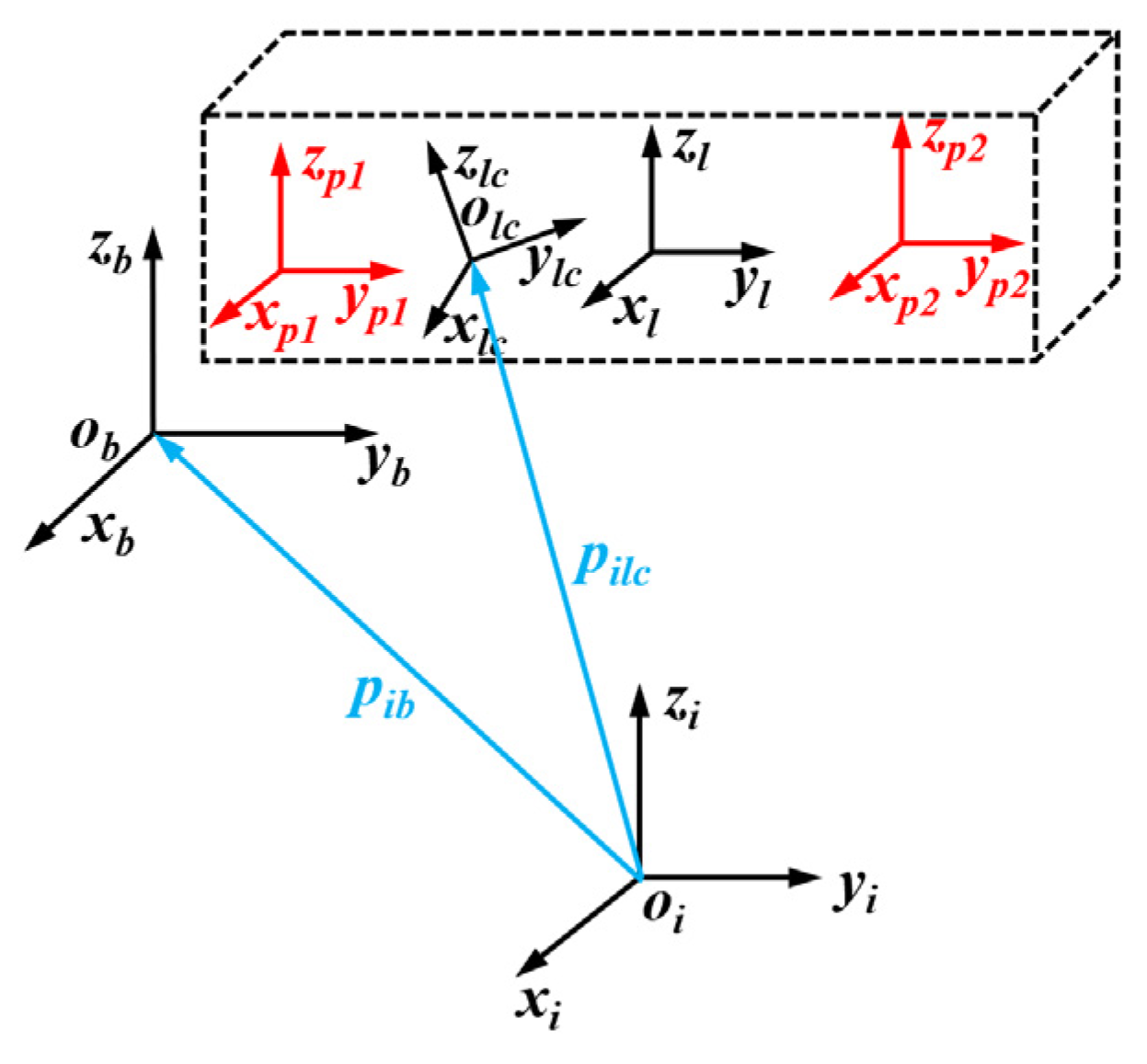
The coordinates system involved in this section is shown in Figure 2. Where {i} is the earth-equatorial coordinates system, {b} is the coordinates system of the space station body, {lc} is the mass center coordinates system of the load, {l} is the centroid coordinates system of the load, {p1} and {p2} are two proxy point coordinates systems.
According to a force analysis of the loads in the space station, the single rigid body dynamic equation is as follows:
𝓕 lc = G lc V ˙ lc [ ad V lc ] T G lc V lc
where 𝓕 lc = [ m lc f lc ] is the force screw of the object acting on the load, G lc = [ lc 0 0 m I ( 3 × 3 ) ] is the space inertia matrix, m is the mass of the load, and V lc is the motion screw of the object at the center of the mass coordinates system of the load.
The total object force screw is divided into two parts, that is, the object force screw 𝓕 ni produced by the non-inertial system and the object force screw 𝓕 lp exerted by the astronauts:
𝓕 lc = 𝓕 ni + 𝓕 lp
The parameter 𝓕 lp can be directly obtained by the six-dimensional force sensor and converted to the force screw of the object, expressed in the coordinates system of the load center of mass by the following formula.
The screw force exerted by the i-th astronaut on the load is denoted as 𝓕 p i in the corresponding proxy point coordinates system, while the pose of the load’s centroid coordinates system {lc} in the i-th proxy point coordinates system is denoted as T p i lc ; so the total body force screw exerted by the i-th astronaut on the payload is:
𝓕 lp = i = 1 n ( [ Ad T p i lc ] T 𝓕 p i )
Substituting the force screw 𝓕 lc into the rigid body dynamics relation, as expressed in Equation (7), can obtain V ˙ lc and then integrate to obtain V lc .
Moreover, V lc is regularized to obtain the screw axis S , whereas V lc = [ ω lc v lc ] . If ω lc 0 , then S = V lc ω lc , the angular velocity θ ˙ = ω lc of the screw axis; if ω lc = 0 , then S = V lc v lc , the angular velocity of the screw axis θ ˙ = v lc . Therefore, the pose of the center of mass coordinates system of the load at the time i in the center of mass coordinates system of the load at a time (i − 1) is: T i 1 , i = e [ S ] ( θ ˙ Δ t ) SE ( 3 ) . Here, Δ t is the sampling time of the system.
Therefore, at time t, the pose of the payload’s centroid coordinates system {lc} in the coordinates system of the space station body {b} can be expressed as follows, noting that the multiplication in the formula is right multiplication.
T blc ( t ) = T blc 0 i = 1 t / Δ t T i 1 , i
where T blc 0 is the initial pose.

2.4. Design of Virtual Force Sensor

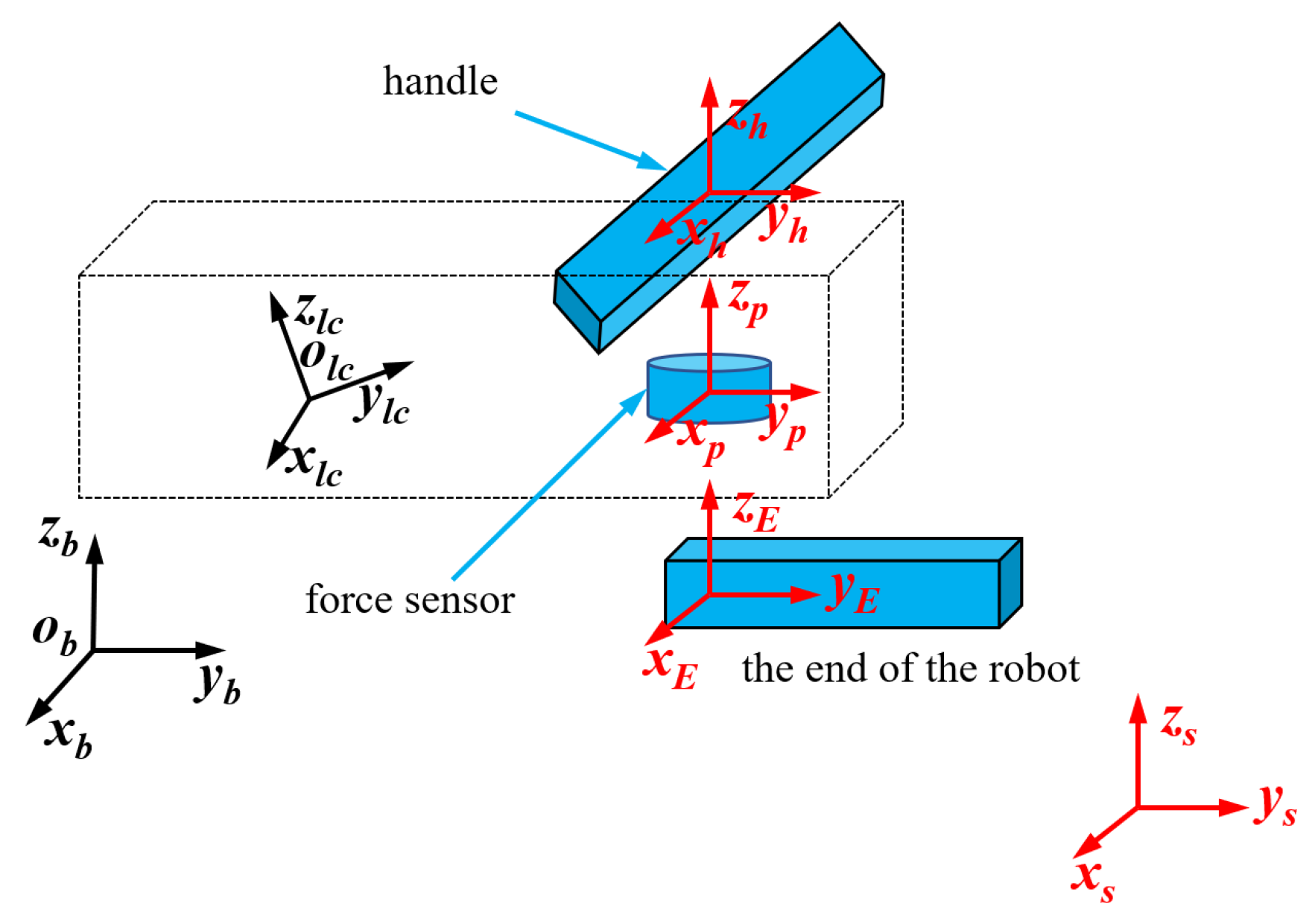
The robot coordinates system is shown in Figure 3. Suppose the pose of the load center of mass coordinates system in the coordinate system of the space station body {b} is T blc , while the poses of the agent point coordinates system {p1} and {p2} in the load center of mass coordinates system {lc} are T lcp 1 and T lcp 2 , respectively. Therefore, the poses of the agent point coordinates system {p1} and {p2} in the coordinate system of the space station body {b} are: T bp 1 = T blc T lcp 1 and T bp 2 = T blc T lcp 2 , respectively. In general, there will be a certain difference between the position of the two agent points and the position of the robot’s end effector because the position of the agent point is considered the position of the force sensor. On the other hand, the position of the force sensor and the position of the robot’s end effector are not necessarily the same. Assuming that the poses of the two force sensors in the end effector coordinates systems of the two robots are T E 1 p 1 and T E 2 p 2 , the poses of the end effector of the robot in the body coordinates system of the space station are T bE 1 = T bp 1 T E 1 p 1 1 and T bE 2 = T bp 2 T E 2 p 2 1 .
Furthermore, if the poses of the base coordinates systems {s1} and {s2} of the two robots in the body coordinates system {b} are: T bs 1 and T bs 2 , respectively, they are also fixed values in a training task. Then, the pose of the coordinate system of the robot end effector in the corresponding robot base coordinates system {s} is:
T s 1 E 1 = T bs 1 1 T bE 1 = T bs 1 1 T blc T lcp 1 T E 1 p 1 1 T s 2 E 2 = T bs 2 1 T bE 2 = T bs 2 1 T blc T lcp 2 T E 2 p 2 1
This pose is needed to solve the robot’s inverse kinematics solution and motion control.
Regarding the virtual force sensor and virtual robot, to simplify the calculation, it is considered that the handle coordinates system {h}, the agent point coordinates system {p}, and the coordinates system of the robot end effector {E} are the same, namely, T Ep = E ( 4 × 4 ) . It should be noted that, at this time, the proxy point coordinates system {p} is not the same as the one used as the control command, but the proxy point coordinates system feedback after the control of the virtual robot; that is, the feedback value of the coordinates system of the robot end effector. In other words, the purpose of virtual robot control is to enable the virtual coordinates system of the robot end effector {E} and the agent point coordinates system {p} to follow the command values of the handle coordinates system {h} and the agent coordinates system {p}. The purpose of the virtual force sensor is to calculate the force screw that needs to be applied to the agent point coordinates system {p}, during this process. The proxy point coordinates system {p} is the medium connecting the virtual load and the virtual robot.
At time t, the pose of the handle coordinates system in the base coordinates system of the virtual robot is denoted as T sh t , while the pose of the virtual robot’s end effector coordinates system {E} in the virtual robot’s base coordinates system is denoted as T sE t . Then, the pose of the handle coordinates system in the end effector coordinates system of the virtual robot is: T Eh t = T sE t 1 T sh t = T lcE t 1 T lch t .In the virtual robot, the coordinates system of the agent point and the coordinates system of the robot end effector are considered to be the same coordinates system, so the pose of the handle coordinates system in the coordinates system of the agent point {p} is actually: T ph t = T Eh t . Specifically, to enable the coordinates system of the agent point to follow the coordinates system of the handle, it is necessary to move the coordinates system of the handle from the pose E ( 4 × 4 ) that coincides with the coordinates system of the agent point to T ph t , within a sampling period Δt, while T ph t = [ R p 0 1 ] = e [ S ] ( θ ˙ Δ t ) , where S = ( ω , v ) = ( ω 1 , ω 2 , ω 3 , v 1 , v 2 , v 3 ) . The next step is to solve for the value of S .
If R = E ( 3 × 3 ) , then ω = 0 , v = p p , θ = θ ˙ Δ t = p . If R E ( 3 × 3 ) , first ω and θ are calculated according to the matrix logarithm of SO ( 3 ) , followed by the calculation: v = ( 1 θ E 1 2 [ ω ] + ( 1 θ 1 2 cot ( θ 2 ) ) [ ω ] 2 ) p .
The procedure for solving ω and θ is as follows:
If the trace of the rotation matrix R  Trace ( R ) = 1 , then θ = π , while ω can take any value of the following three cases:
ω = 1 2 ( 1 + R 33 ) [ R 13 R 23 1 + R 33 ] or ω = 1 2 ( 1 + R 22 ) [ R 12 1 + R 22 R 32 ] or ω = 1 2 ( 1 + R 11 ) [ 1 + R 11 R 21 R 31 ]
Otherwise, θ = acos ( 1 2 ( Trace ( R ) 1 ) ) [ 0 , π ) , [ ω ] = 1 2 sin ( θ ) ( R R T ) .
Therefore, the motion screw from E ( 4 × 4 ) to T ph t is expressed in the proxy point coordinates system as V t = S θ ˙ . More specifically, within time Δ t , the average value of the object motion screw in the agent point coordinates system needs to reach V t , so that the agent point coordinates system can follow the handle coordinates system. In this paper, considering that the object motion screw based on the object coordinates system does not depend on the fixed coordinates system selection, the virtual robot’s base coordinates system is selected as the fixed coordinates system. At the end of the time step Δ t , the object motion screw in the agent point coordinates system or the coordinate system of the virtual robot end effector is: [ V t ] = T sE t 1 T ˙ sE t . Therefore, the acceleration is V ˙ t = 2 V t V t Δ t . The space inertia matrix expressed in the proxy point coordinates system is G p = [ Ad T lcp ] T G lc [ Ad T lcp ] . Substituting G p , V ˙ t and V t into the rigid body dynamics equation can obtain the force screw 𝓕 .
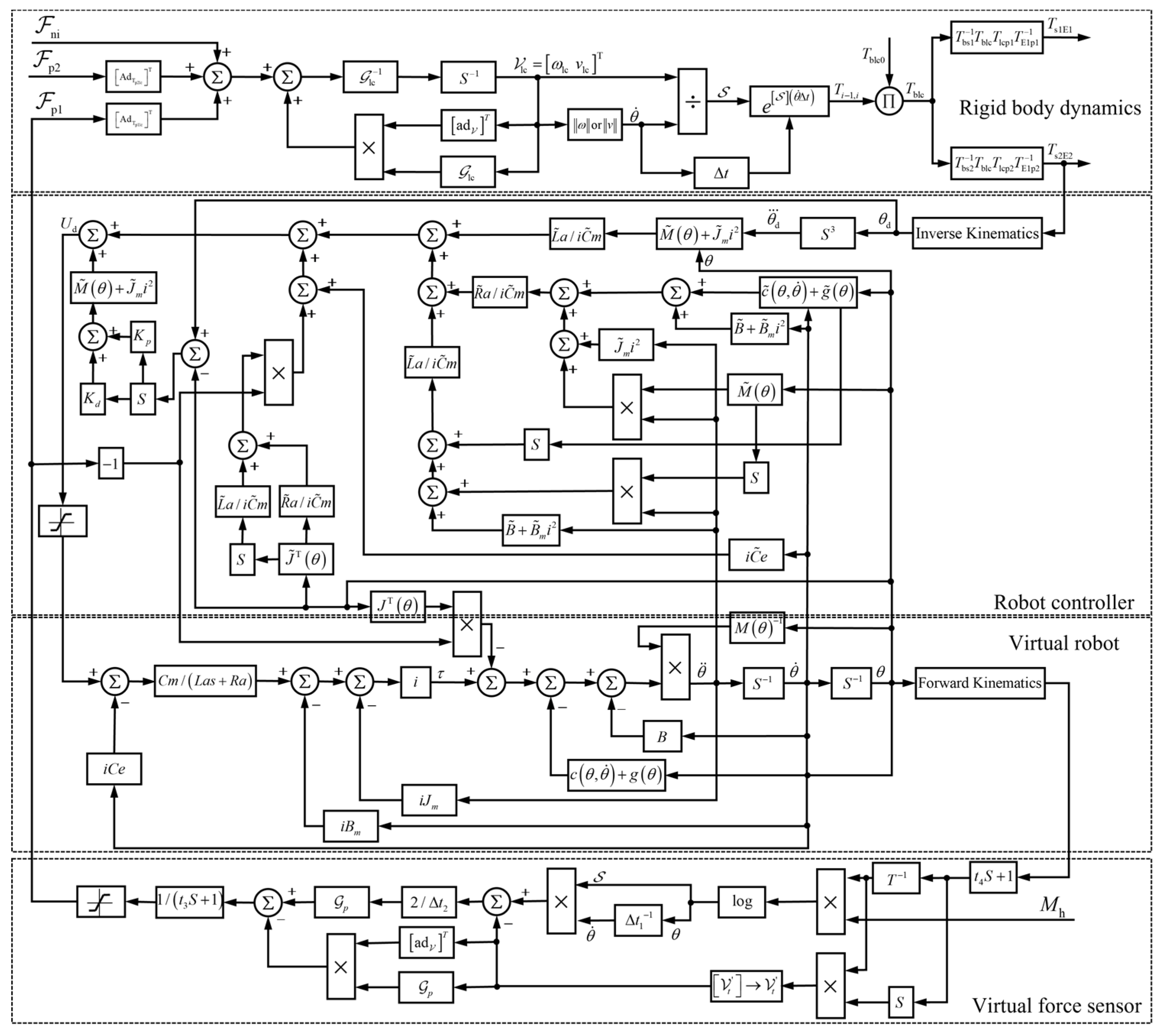
The block diagram of the system in this process is shown in Figure 4. Among them, M h is the pose of the handle coordinates system given by the VR handle, 𝓕 ni is the non-inertial force screw and 𝓕 p 2 is the human-computer interaction force of the astronaut operating the real robot.
Theoretically, the Δ t 1 and Δ t 1 of the virtual force sensor component in Figure 4 should both be the sampling period Δ t . Parameters Δ t 1 and Δ t 2 can be set at different values to improve the performance of the control system. At the same time, a filter link is connected in series to the output of the virtual force sensor to attenuate the medium and high-frequency signals and limit the output. A differential link is connected in parallel with the virtual robot’s terminal pose output to improve the system’s stability. To select the appropriate time constant Δ t 1 , Δ t 2 , filter parameter t 3 , and differential constant t 4 , the motion of one of the robot’s degrees of freedom is first selected for analysis.
Since the robot controller adopts the inverse system method, it is theoretically possible to cancel the transfer functions of the robot controller and the virtual robot. However, there is still a difference between the transfer function of the robot controller and the virtual robot. Especially after the PD controller is introduced, the two cannot cancel each other out.
The expression of the PD controller is:
U d 3 ( t ) = ( J ˜ e ( θ ) K p + J ˜ e ( θ ) K d s ) ( θ d ( s ) θ ( s ) )
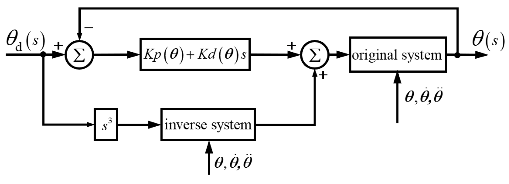
Among them, J ˜ e ( θ ) is the estimated value of the equivalent moment of inertia of the joint, which is only related to the joint angle behind the current joint but not to the current joint itself. In the case of only one single degree of freedom being considered, it can be treated as a constant. Considering that, J ˜ e ( θ ) K p = K p ( θ ) , J ˜ e ( θ ) K d = K d ( θ ) , the block diagram of the system function of a single joint is shown in Figure 5.
The input of the original system U d ( s ) can be expressed as:
U d ( s ) = L ˜ a i C ˜ m ( i 2 J ˜ e ( θ ) θ d s 3 + τ ˜ Load ( θ , θ ˙ , θ ¨ ) s + i 2 B ˜ e θ s 2 ) + R ˜ a i C ˜ m ( i 2 J ˜ e ( θ ) θ s 2 + τ ˜ Load ( θ , θ ˙ , θ ¨ ) + i 2 B ˜ e θ s ) + C ˜ e i θ s + K p ( θ ) ( θ d θ ) + K d ( θ ) ( θ d θ ) s
where τ ˜ Load ( θ , θ ˙ , θ ¨ ) = c ˜ ( θ , θ ˙ ) + g ˜ ( θ ) + τ ˜ F ( θ ) + m ˜ ( θ ¨ ) . This variable represents the influence of other joints on this joint. When considering a single degree of freedom, the following applies: θ ˙ = θ ¨ = 0 .
In Equation (13), the symbol ~ above a variable indicates that the variable is an estimated value. The parameter J ˜ e ( θ ) is the equivalent moment of inertia equal to J ˜ e ( θ ) = J ˜ m + 1 i 2 J ˜ ( θ ) and B ˜ e is the equivalent damping coefficient equal to B ˜ e = B ˜ m + 1 i 2 B .
The output of the original system is:
θ ( s ) = C m C ˜ m ( L ˜ a s + R ˜ a ) τ ˜ Load ( θ , θ ˙ , θ ¨ ) ( L a s + R a ) τ Load ( θ , θ ˙ , θ ¨ ) s ( J e ( θ ) s + B e ) ( L a s + R a ) i 2 + C m C ˜ m ( L ˜ a ( J ˜ e ( θ ) θ d s 3 + B ˜ e θ s 2 ) + R ˜ a s ( J ˜ e ( θ ) θ s + B ˜ e θ ) ) s ( J e ( θ ) s + B e ) ( L a s + R a ) + C m ( C ˜ e C e ) θ ( J e ( θ ) s + B e ) ( L a s + R a ) + C m ( K p ( θ ) ( θ d θ ) + K d ( θ ) ( θ ˙ d θ ˙ ) ) s ( J e ( θ ) s + B e ) ( L a s + R a ) i
When all estimates are equal to actual values, θ ( s ) = θ d ( s ) , the PD controller does not work. Therefore:
θ = L a ( J e ( θ ) θ d s 3 + B e θ s 2 ) + R a s ( J e ( θ ) θ s + B e θ ) s ( J e ( θ ) s + B e ) ( L a s + R a ) = θ d
The above relation proves to be always established. The validity of the design of the inverse system can be verified.
In case the estimated value is not equal to the actual value, to obtain the order of the transfer function, the external load moment of the motor is not considered, or it is considered as such: C m C ˜ m ( L ˜ a s + R ˜ a ) τ ˜ Load ( θ , θ ˙ , θ ¨ ) ( L a s + R a ) τ Load ( θ , θ ˙ , θ ¨ ) = 0 . Hence, Equation (14) can be written in the following form:
G 1 ( s ) = θ ( s ) θ d ( s ) = b 0 ( θ ) s 3 + b 1 ( θ ) s 2 + b 2 ( θ ) s + b 3 ( θ ) a 0 ( θ ) s 3 + a 1 ( θ ) s 2 + a 2 ( θ ) s + a 3 ( θ ) ,
where
{ a 0 ( θ ) = C ˜ m i L a J e ( θ ) a 1 ( θ ) = C ˜ m i J e ( θ ) R a C m i J ˜ e ( θ ) R ˜ a + C ˜ m i B e L a C m i L ˜ a B ˜ e a 2 ( θ ) = C ˜ m i B e R a C m i B ˜ e R ˜ a C m C ˜ m ( C ˜ e C e ) + C m C ˜ m K d ( θ ) a 3 ( θ ) = C m C ˜ m K p ( θ ) b 0 ( θ ) = C m i L ˜ a J ˜ e ( θ ) b 1 ( θ ) = 0 b 2 ( θ ) = C m C ˜ m K d ( θ ) b 3 ( θ ) = a 3 ( θ )
The transfer function shows that the following is true θ ( s ) = θ d ( s ) when all the estimated values are equal to the actual values.
The single joint model of the virtual force sensor is shown in Figure 6.

3. Results

The proposed algorithm was simulated and verified on a single person carrying an object and two people cooperating to carry an object. Furthermore, two virtual robot models were established, and the proposed algorithm was experimentally validated via a two-person antagonism.

3.1. Simulation Results When a Single Person Carries Objects

The controller parameters are set as: Δ t 1 = 0.042 , Δ t 2 = 15 , t 3 = 0.1215 , t 4 = 0.15 , while MATLAB is used to establish the simulation model, and the system sampling period is set to 0.001 s.
The pose M h of the VR handle is given by the position ( x d , y d , z d ) , and the Euler angle ( ϕ d , θ d , ψ d ) of the VR handle. The given signals are all sine waves, and the position ( x , y , z ) and Euler angle ( ϕ , θ , ψ ) of the end effector of the robot are shown in Figure 7.
Figure 7 shows that the robot’s end effector can better follow the given position of the VR handle while the system is in a stable state.
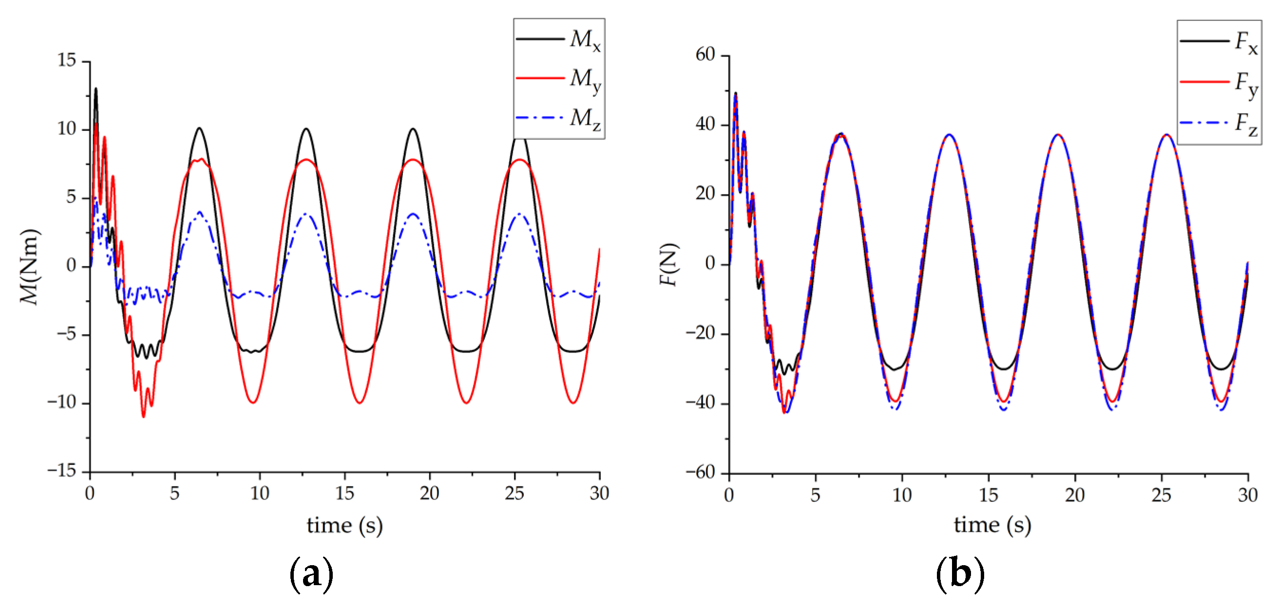
The output of the virtual force sensor 𝓕 p 1 = ( M x , M y , M z , F x , F y , F z ) during this process is shown in Figure 8.
Figure 8 illustrates that the output of the virtual force sensor will oscillate during the first period and enter a stable state after a single cycle due to the sudden change of the force screw at the initial moment.

3.2. Simulation Results When Two People Cooperate in Carrying Objects

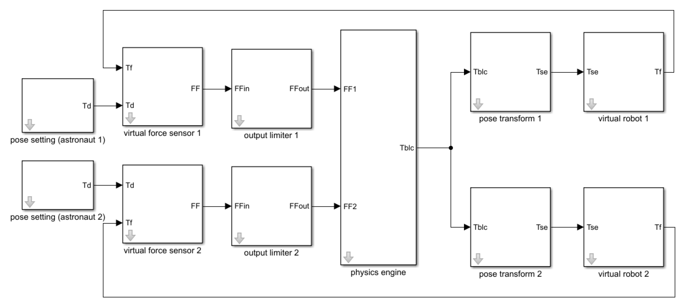
The virtual force sensor proposed in this paper is mainly used in virtual training when two people cooperate in carrying objects. Matlab is used to establish a simulation model of two people cooperatively carrying objects to verify the effect of the virtual force sensor when two people cooperate, as shown in Figure 9.
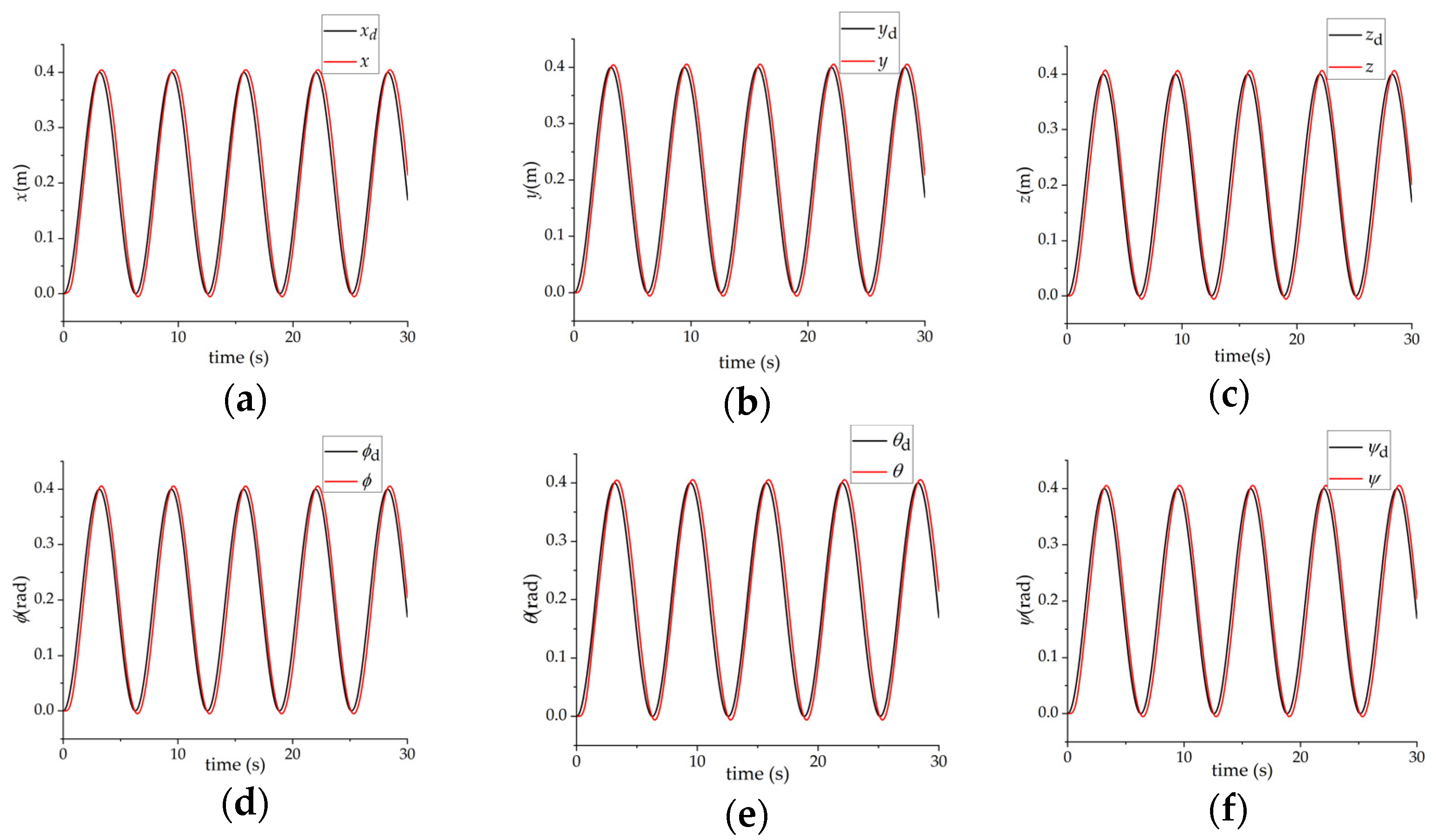
The pose output of the virtual object considering two sets of the same sine wave signals as the pose input is shown in Figure 10. Compared to the case of a single-person handling objects, the overshoot of the pose-following output is slightly larger in the case of two people carrying objects together. However, the system is still in a stable state, which is consistent with the daily life experience. Compared to single-person handling, the accuracy of two people cooperating to carry objects is slightly worse and easy to overshoot.
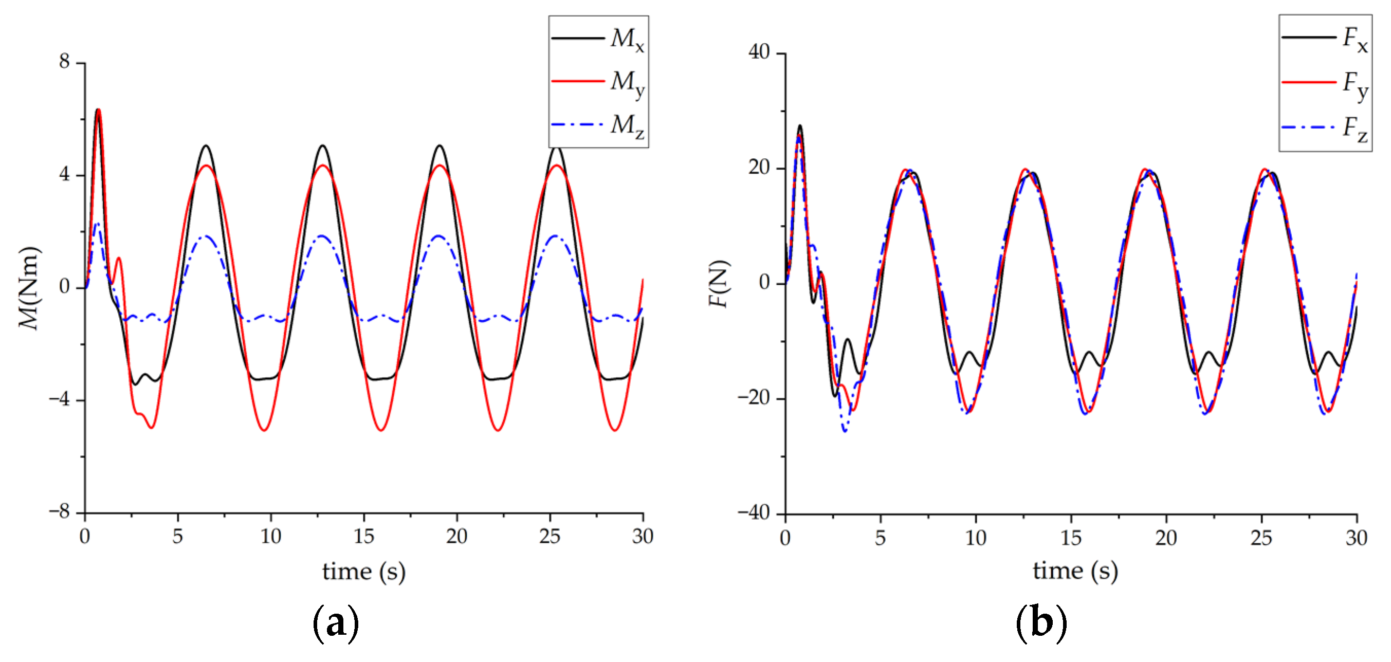
When two people carry objects, the output of the virtual force sensor 1 𝓕 p 1 = ( M x , M y , M z , F x , F y , F z ) is shown in Figure 11, i.e., the output is exactly half of that of a single person carrying objects. This is consistent with the common daily life experience where, compared to single-person handling objects, it is more effortless when two people cooperate in carrying objects.
The above simulations are based on the assumption that the given positions of the two astronauts are the same; that is, the two astronauts have the same goal. In actual situations, the goals of the two astronauts are not necessarily the same, and they may even be in a state of mutual antagonism. Next, the simulation of two astronauts cooperatively carrying objects is carried out according to the following scenarios and conditions.
(1)
At the initial moment ( x 0 , y 0 , z 0 ) = ( 0 , 0 , 0 ) , the initial Euler angles of the virtual object are: ( ϕ 0 , θ 0 , ψ 0 ) = ( 0 , 0 , 0 ) ;
(2)
The goal of Astronaut 1 is to transport the virtual object to the pose corresponding to ( x d 1 , y d 1 , z d 1 ) = ( 0.4 , 0.4 , 0.4 ) and ( ϕ d 1 , θ d 1 , ψ d 1 ) = ( 0.4 , 0.4 , 0.4 ) . The goal of Astronaut 2 is to keep the pose of the virtual object constant.
(3)
Astronaut 1’s minimum and maximum output force screw, that is, the output limit is: (±60 Nm, ±60 Nm, ±60 Nm, ±400 N, ±400 N, ±400 N), Astronaut 2’s minimum and maximum output force screw, that is, the output limit is: (±30 Nm, ±30 Nm, ±30 Nm, ±200 N, ±200 N, ±200 N).
The simulation results are shown in Figure 12, where ( x , y , z ) and ( ϕ , θ , ψ ) represent the position and Euler angle of the virtual object, respectively.
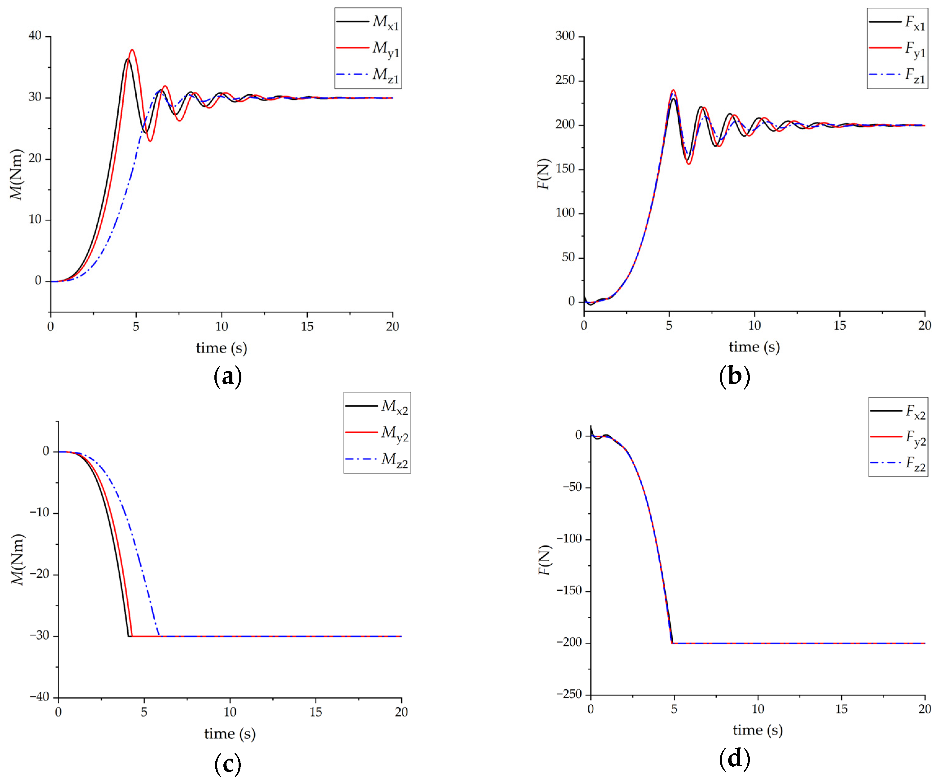
According to Figure 12, the final position of the virtual object is neither the target position of astronaut 1 nor the target position of astronaut 2, but a position somewhere in between. Moreover, the final position of the virtual object appears closer to the target position because astronaut 1’s maximum output force of astronaut 1 is larger. Based on Figure 12, under the same controller parameters, the system’s instability appears to increase in the state of mutual antagonism compared to the single-person handling. The output graphs of the virtual force sensor 1 and virtual force sensor 2 (Figure 13) show that, after a period of oscillation, the output of virtual force sensor 1 is in a relatively stable state, while the output of the virtual force sensor 2 is in a saturated state. After stabilization, the output of virtual force sensor 2 is in a saturated state. In contrast, the output of virtual force sensor 1 is close to the negative value of the output of the virtual force sensor 2, which, coupled with the object force screw generated by the non-inertial system, sums up approximately to zero. The virtual object is finally in a relatively static state, but there will still be slight oscillations with continuously declining amplitudes.
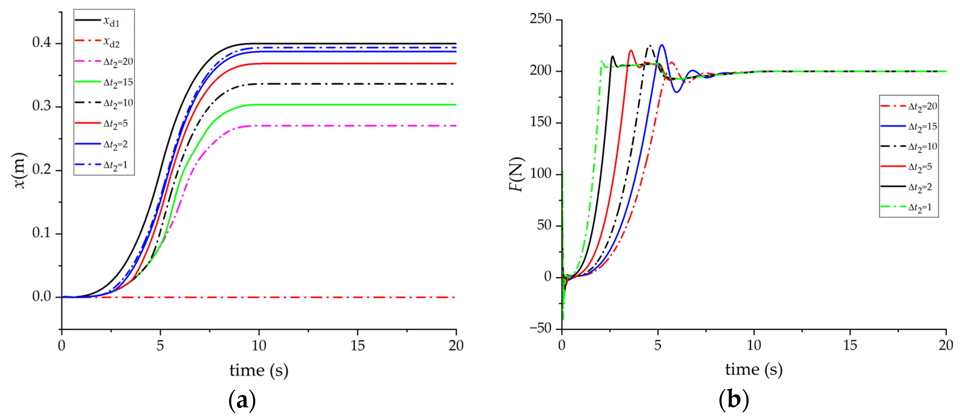
To verify the influence of Δ t 1 and Δ t 2 , first Δ t 2 = 15 is set, while Δ t 1 is set to different values, producing simulation results in the x direction, as shown in Figure 14. It is evident that the smaller Δ t 1 is, the closer the final position x of the virtual object is to x d 1 . Moreover, Δ t 1 = 0.042 is set, while Δ t 2 is set to different values, producing simulation results in the x direction as shown in Figure 15. Evidently, the smaller Δ t 2 is, the closer the final position of the virtual object x is to x d 1 . For simplicity, the results of other directions are not shown, but they follow similar rules.

3.3. Experimental Results

Due to limiting conditions, this paper does not conduct a collaborative experiment between real and virtual robots. Instead, two virtual robots are used for experiments. The virtual robot runs on the dSpace semi-physical simulation platform, a real-time system that can ensure the real-time operation of the virtual robot. Pose settings are provided by the VR handle of HTC VIVE pro. The VR handle’s pose is obtained through Unity on the PC’s Windows system. In contrast, the pose of the two handles is sent, through RS422 communication, to the dSpace semi-physical simulation platform, where the pose of the virtual object and the VHMIF are calculated.
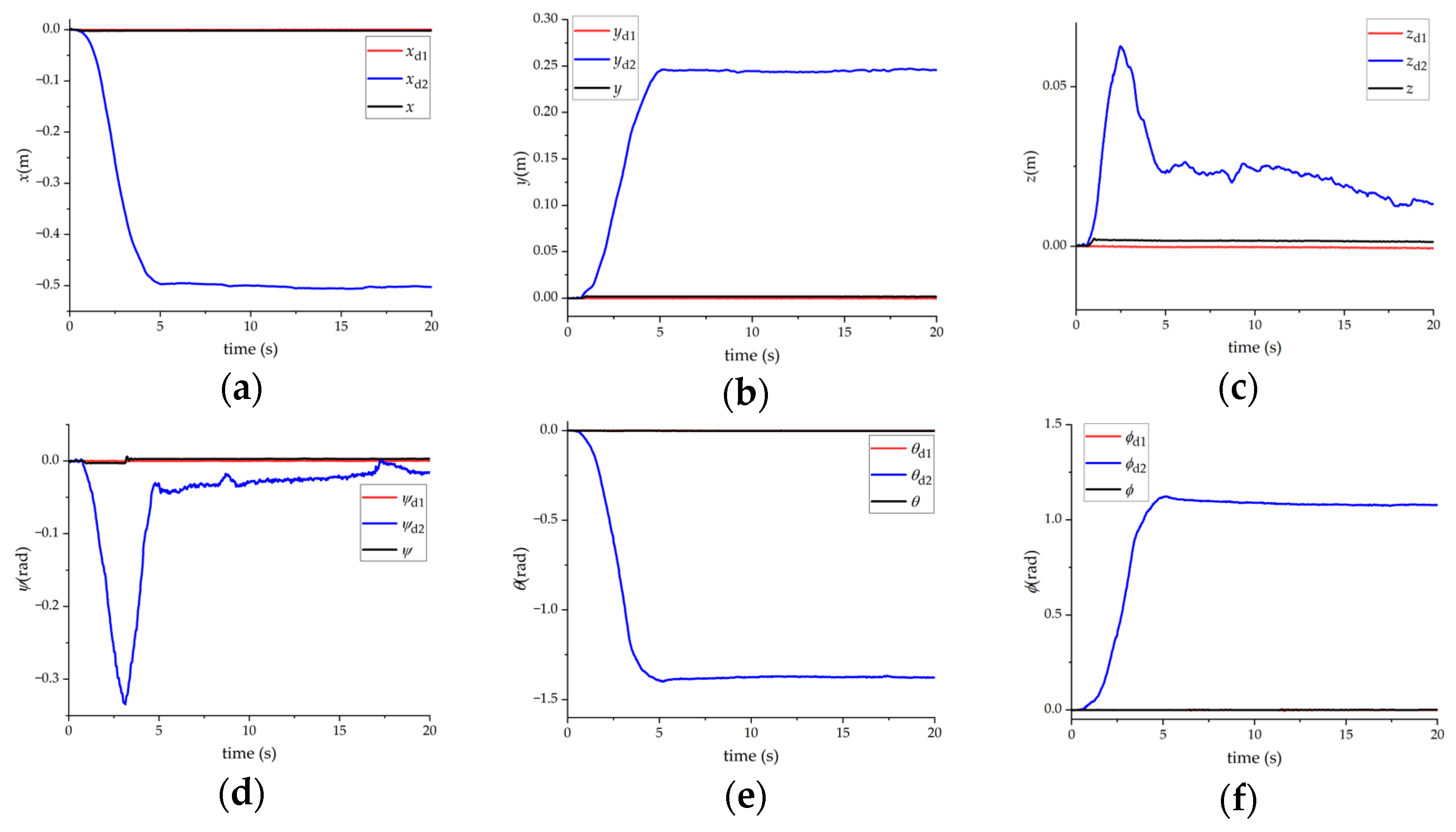
In this paper, two experiment sets are set up, and the experimental conditions are shown in Table 1. Furthermore, tester 1’s minimum and maximum output screw forces are (±60 Nm, ±60 Nm, ±60 Nm, ±400 N, ±400 N, ±400 N), and tester 2’s minimum and maximum output screw forces are (±30 Nm, ±30 Nm, ±30 Nm, ±200 N, ±200 N, ±200 N).
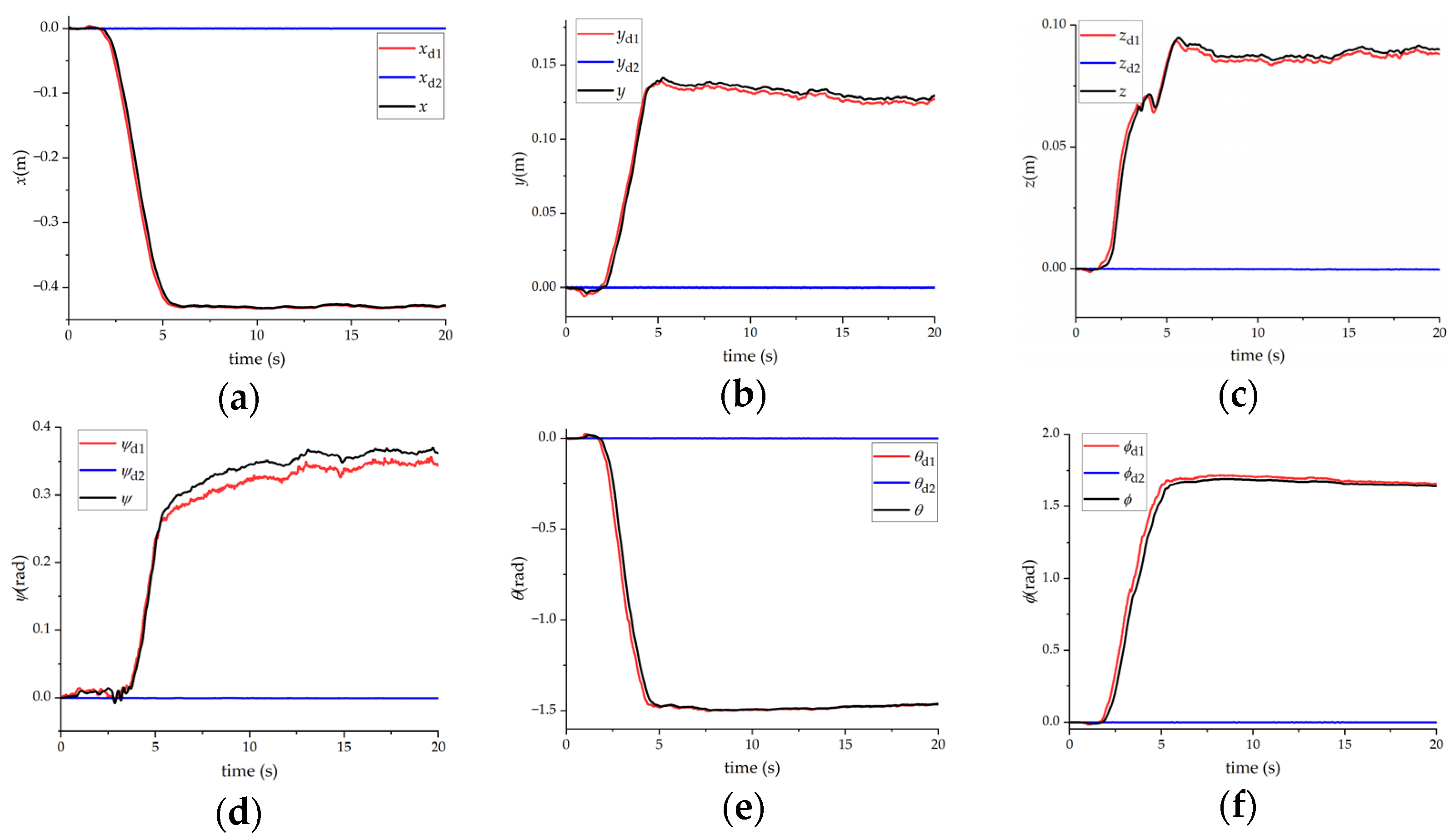
The results of the first experiment are shown in Figure 16, where x d 1 , y d 1 , z d 1 , ϕ d 1 , θ d 1 , and ψ d 1 represent the pose of tester 1′s VR handle. Parameters x d 2 , y d 2 , z d 2 , ϕ d 2 , θ d 2 , and ψ d 2 represent the pose of the tester 2′s VR handle. Lastly, parameters x , y , z , ϕ , θ , and ψ represent the pose of the virtual object. According to Figure 16, the final pose of the virtual object is closer to the pose of tester 1’s VR handle.
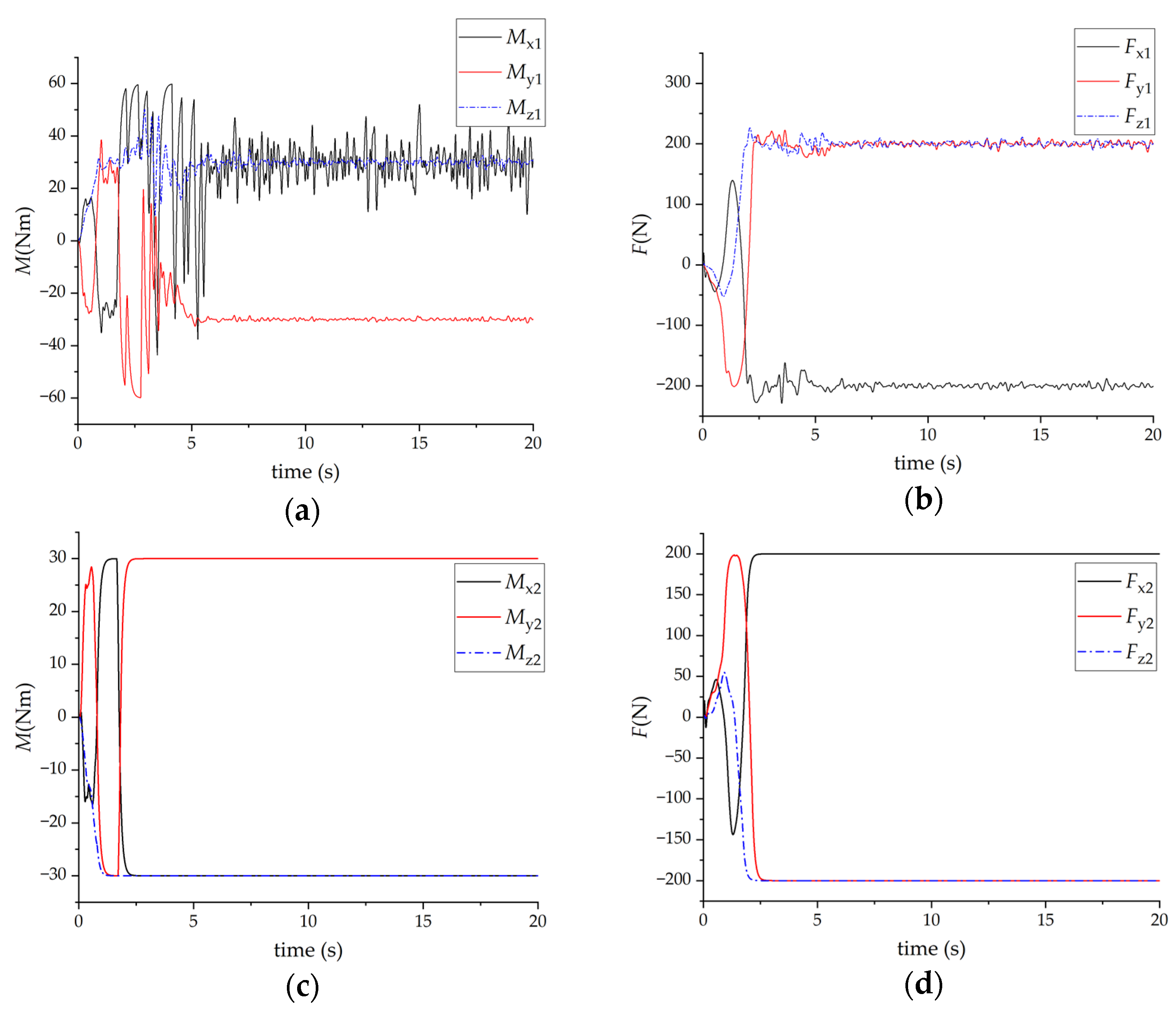
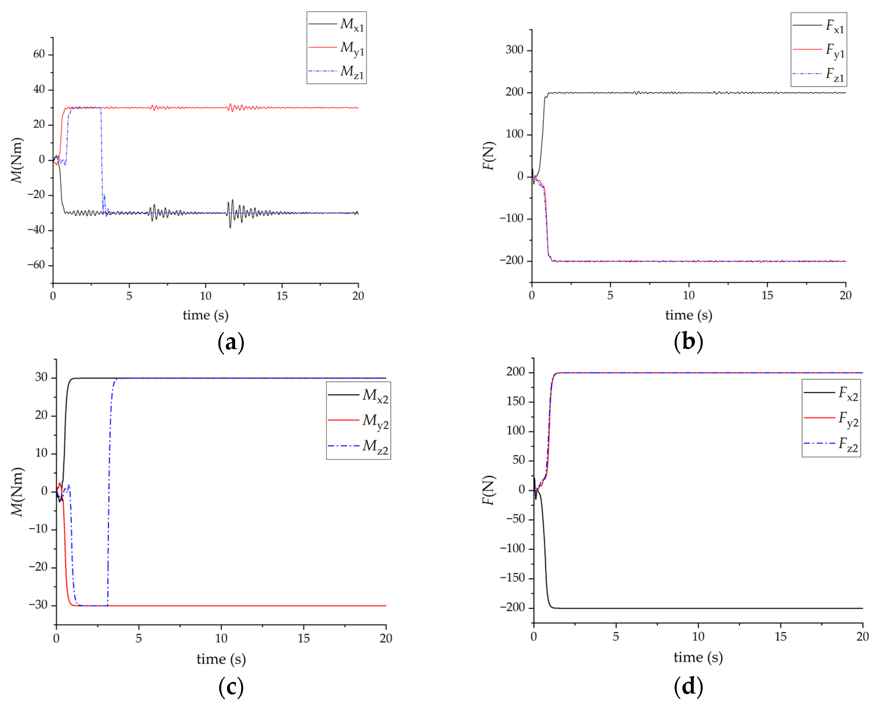
The VHMIF, as measured by the virtual force sensor during this process, is shown in Figure 17, where 𝓕 p 1 = ( M x 1 , M y 1 , M z 1 , F x 1 , F y 1 , F z 1 ) represents the output of the virtual force sensor 1 and 𝓕 p 2 = ( M x 2 , M y 2 , M z 2 , F x 2 , F y 2 , F z 2 ) represents the output of the virtual force sensor 2. According to Figure 17, the virtual force sensor 2 is finally saturated.
The results of the second experiment are shown in Figure 18. Variables in Figure 18 are the same as those in Figure 16. According to Figure 18, the final pose of the virtual object is closer to the pose of the tester 1’s VR handle.
The VHMIF, as measured by the virtual force sensor, during this process, is shown in Figure 19. Variables in Figure 19 are the same as those in Figure 17. According to Figure 19, the virtual force sensor 2 is finally in a saturated state.

4. Discussion

According to Figure 14 and Figure 15, the smaller Δ t 1 and Δ t 2 are, the closer the final position of the virtual object x is to x d 1 . The final position of the virtual object is determined by the astronaut whose maximum output force spin is the highest. According to the scenario set in this paper, the final position of the virtual object is determined by astronaut 1. According to Figure 6, the output of the virtual force sensor in the case of a single joint can be expressed as:
F 1 = M x d 1 x 1 Δ t 1 x ˙ 1 2 Δ t 2 ,
where M is the mass of the virtual object and x 1 is the actual position of virtual robot 1.
Therefore,
x d 1 x 1 = ( 2 F 1 Δ t 2 M + x ˙ 1 ) Δ t 1
In the case where the control effect of the robot controller is good, lim t x 1 ( t ) = x , where x is the position of the virtual object, lim t x ˙ 1 ( t ) = 0 and | lim t F 1 ( t ) | = F min . Therefore:
x d 1 x = 2 F min Δ t 1 Δ t 2 M
The above formula shows that the smaller Δ t 1 Δ t 2 is, the smaller F min is. In contrast, the larger M is, the smaller | x d 1 x | is, and the deviation between the final position of the virtual object x and the given position x d 1 is smaller. Setting: Δ x = x d 1 x , then:
F min = M 2 Δ t 1 Δ t 2 Δ x = K Δ x
where K is called the generalized stiffness of the virtual force sensor, and its meaning is equivalent to the stiffness of the deflection structure of the real force sensor. When K increases, the difference between the position of the virtual object and the handle is smaller, and vice versa. The results of the theoretical analysis agree with the simulation.
According to Figure 16, although the pose obtained by the VR handle has much noise, the system can still maintain a relatively stable state, while the final pose of the virtual object is determined by tester 1 with greater strength. Although there is a certain deviation between the pose of the virtual object and the given pose of tester 1, considering that the generalized stiffness of the virtual force sensor is not infinite, this deviation is within an acceptable range. If this difference needs to be further reduced, the generalized stiffness of the virtual force sensor can be increased. However, the output fluctuation of the virtual force sensor will also increase, placing the system in an unstable state and amplifying the noise.
In Figure 17, in the first 2.5 s, the outputs of virtual force sensors 1 and 2 are not saturated, while the pose of the virtual object is not determined by tester 1 nor tester 2 but is basically in the middle of the two positions. After 2.5 s, the output of the virtual force sensor 2 is in a saturated state. In contrast, the pose of the virtual object gradually follows the given pose of tester 1′s VR handle, meaning the virtual object’s pose will not be saturated. Although tester 2 did not push the object, under the influence of tester 1, tester 2 also felt the HMIF, as illustrated in Figure 17.
Figure 18 and Figure 19 also lead to the same conclusion. The final pose of the virtual object is determined by the more powerful tester 1, while the object does not move. Similarly, although tester 1 did not push the object, under the influence of tester 2, tester 1 also felt the HMIF.
Compared to the method proposed in [10], the presented method in this paper is suitable for the situation of six degrees of freedom in space. Since the method proposed in [10] does not apply to the case of six degrees of freedom, the following comparison is only made with a single degree of freedom.
A command signal of 0.4 m is provided in the x direction. Simultaneously, noise is superimposed. For the same controller parameters of the virtual robot, the effects of the virtual force sensor under the two methods are shown in Table 2.
According to Table 2 and compared with the algorithm in [10], the proposed algorithm has a smaller output noise of the virtual force sensor for a similar rise time. However, the proposed algorithm requires a longer solution time, but the real-time performance is still satisfied.
Figure 13, Figure 14 and Figure 15 show that, even in the absence of noise interference, the output of the unsaturated virtual force sensor still exhibits a certain oscillation. At the same time, this overshoot is difficult to avoid, contributing to the overall. Since the quadratic integral of the force screw of the object is positive, the virtual object finally follows the instruction of trainee 1. One of the next research directions is minimizing the overshoot and the number of oscillations.
As proposed in this paper, the virtual force sensor is a complex, nonlinear, multiple-input and multiple-output, time-varying control system. However, its stability was not analyzed in this paper. At the same time, the appropriate selection of controller parameters so that the whole system has improved stability, speed, and stronger robustness, is also a key research direction in the future.

5. Conclusions

This paper presented a human–machine interaction force estimation algorithm suitable for astronaut collaborative virtual training to drive the physics engine. According to the experimental results, the final position of the virtual object is determined by the tester with greater strength. This is consistent with real-life experience and can demonstrate the model’s effectiveness. Moreover, in a realistic antagonistic situation, even if a single person needs to hold the object still, that person can feel the force due to the other person’s action on the object. In other words, when two people carry an object, the force exerted by a single person on the object is affected by the other person. This is consistent with experimental results. For the traditional method, the acceleration is obtained by directly calculating the second derivative of the position of the VR (virtual reality) handle, obtaining the input force. Since the position of the VR handle does not change, the calculated force is zero. This is not realistic in the case of two-person antagonism. However, the algorithm proposed in this paper is more in line with the actual situation, i.e., even if the position of the VR handle does not change, the obtained human–machine interaction force is still not zero.
Although the two people in collaborative virtual training are not connected physically, the two people interact through the physical engine to affect each other in the algorithm proposed in this paper. The virtual human–machine interaction forces of the two testers are similar in value but opposite in sign, which can be understood as action and reaction forces. In summary, compared to directly mapping the pose of the VR handle to the HMIF, integrating the physical engine and the virtual robot is more suitable for the collaborative virtual training of astronauts, as proposed in this paper.
This paper mainly focused the ground training of two astronauts jointly handling a very heavy object in the space station. Without the participation of the real robot, two trainees each used a VR handle as an input device. However, it is not necessary to use a VR handle; any device that can recognize the posture of the hand is satisfactory. In the author’s project, using the VR handle will not increase other costs since the VR system is employed as the display device. The trainee uses the VR handle to simulate the pose of a certain agent point of the object to be transported. Subjectively, the trainee feels as though he is carrying an object, but there is no force feedback. The trainee operates the VR handle as if he is operating a real object. During this process, the force that the trainee applies to the virtual object can be obtained, which is the purpose of the algorithm proposed in this paper. If heightened presence is required, one of the trainees can use a robot with force sensors to create force feedback. Therefore, a virtual robot was introduced in this paper for structural symmetry. In other words, this paper proposed a human–computer interaction method to facilitate collaborative virtual training of astronauts by the computer.

Author Contributions

Conceptualization, L.L. and L.Z.; methodology, L.L. and F.X.; validation, L.W. and Y.C.; formal analysis, L.L. and Y.C.; writing—original draft preparation, L.L. and F.X.; writing—review and editing, L.L. and L.W.; supervision, L.Z. and L.W.; project administration, L.Z.; funding acquisition, L.Z. All authors have read and agreed to the published version of the manuscript.

Funding

This research was funded by the National Natural Science Foundation of China, grant number 61773007.

Data Availability Statement

Not applicable.

Conflicts of Interest

The authors declare no conflict of interest.

Nomenclature

The following variables are used in this manuscript:
B the damping coefficient matrix of the robot
B e the equivalent damping coefficient
B m the damping coefficient matrix of the motor
c ( θ , θ ˙ ) the Coriolis force and centrifugal force
( θ , θ ˙ , θ ¨ ) the   first   derivative   of   c ( θ , θ ˙ )
C e the back electromotive force constant matrix of the motor
C m the motor torque constant matrix
𝓕 lc the force screw of the object acting on the load
𝓕 lp the object force screw exerted by the astronauts
𝓕 ni the object force screw produced by the non-inertial system
𝓕 p i the force screw exerted by the i-th astronaut on the load
𝓕 tip the external force screw applied to the end of the robot
g ( θ ) the moment of gravity
G ( θ , θ ˙ ) the   first   derivative   of   g ( θ )
G lc the space inertia matrix of the load
G p the space inertia matrix expressed in the proxy point coordinates system
i the transmission ratio matrix
i a the current of the motor
J the Jacobian matrix of the forward kinematics
J e ( θ ) the equivalent moment of inertia
J m the motor moment of inertia matrix
K the generalized stiffness of the virtual force sensor
K d the derivative coefficient matrix of the PD controller
K p the proportional coefficient matrix of the PD controller
L a the motor inductance matrix
L a i the inductance of the i-th joint motor
m the mass of the load
M ( θ ) the mass matrix of the robot
𝕄 ( θ , θ ˙ ) the   first   derivative   of   M ( θ )
M b 0 the initial pose of the end coordinate system {b}
R a the motor armature resistance matrix
S the screw axis of the load
S i the screw coordinate of joint i
T b the pose of the end coordinates system {b}
T bE i the pose of the end effector of the i-th robot in the body coordinates system of the space station
T blc the pose of the payload’s centroid coordinates system {lc} in the space station body coordinates system {b}
T blc 0 the initial pose of the payload’s centroid coordinates system {lc} in the space station body coordinates system {b}
T bp i the poses of the agent point coordinates system {pi} in the space station body coordinates system {b}
T bs i the pose of the base coordinates systems {si} of the robot in the body coordinates system {b}
T E i p i the pose of the i-th force sensor in the end effector coordinate system of the i-th robot
T i 1 , i the pose of the center of mass coordinates system of the load at the time i in the center of mass coordinates system of the load at a time (i − 1)
T lcp i the pose of the agent point coordinates system {pi} in the load center of mass coordinates system {lc}
T ph the pose of the handle coordinates system in the coordinates system of the agent point {p}
T sE the pose of the virtual robot’s end effector coordinates system {E} in the virtual robot’s base coordinates system
T sh the pose of the handle coordinates system in the base coordinates system of the virtual robot
Δ t the sampling time of the system
Δ t 1 the first time-constant of the virtual force sensor
Δ t 1 the second time constant of the virtual force sensor
t 3 the filter parameter of the virtual force sensor
t 4 the differential constant of the virtual force sensor
U the input of the original virtual robot system
U a the armature voltage of the motor
U d 1 The first part of the inverse system output
U d 2 The second part of the inverse system output
V lc the motion screw of the object at the center of the mass coordinates system of the load
V t the   motion   screw   from   E ( 4 × 4 )   to   T ph   expressed   in   the   proxy   point   coordinates   system
θ the joint angle matrix of the robot
θ ˙ the angular velocity of the screw axis
θ ˙ a the angular velocity of the motor
θ d the angle/displacement command matrix
τ the driving torque of robot joints
τ 1 the moment of inertia, Coriolis force, gravity moment, damping moment
τ 2 the torque generated by the motor that is applied to the external environment by the robot end link

Appendix A

The dynamic equation of the robot can be expressed in two parts:
{ τ 1 = M ( θ ) θ ¨ + c ( θ , θ ˙ ) + g ( θ ) + B θ ˙ τ 2 = J T ( θ ) 𝓕 tip
where τ 1 is the moment of inertia, Coriolis force, gravity moment, damping moment, etc., and τ 2 is the torque generated by the motor that is applied to the external environment by the robot end link 𝓕 tip .
Derivation of Equation (A1) can be obtained as:
{ τ ˙ 1 = M ˙ ( θ ) θ ¨ + M ( θ ) θ + c ˙ ( θ , θ ˙ ) + g ˙ ( θ ) + B θ ¨ = 𝕄 ( θ , θ ˙ ) θ ¨ + M ( θ ) θ + ( θ , θ ˙ , θ ¨ ) + G ( θ , θ ˙ ) + B θ ¨ τ ˙ 2 = J ˙ T ( θ ) 𝓕 tip + J T ( θ ) 𝓕 ˙ tip = J ( θ , θ ˙ ) 𝓕 tip + J T ( θ ) 𝓕 ˙ tip
According to the DC motor model:
{ τ = i ( C m i a J m θ ¨ a B m θ ˙ a ) = i ( C m i a J m i θ ¨ B m i θ ˙ ) τ ˙ = i ( C m i ˙ a J m i θ B m i θ ¨ ) U a = R a i a + L a i ˙ a U a = U d C e θ ˙ a = U d C e i θ ˙
where τ is the driving torque of the joint, i is the reduction ratio, U d is the control voltage, i a is the current of the motor, U a is the armature voltage of the motor, and θ ˙ a is the angular velocity of the motor.
Similarly, Equation (A3) is divided into two parts:
{ τ 1 = i C m i a 1 J m i 2 θ ¨ B m i 2 θ ˙ , τ 2 = i C m i a 2 τ ˙ 1 = i C m i ˙ a 1 J m i 2 θ B m i 2 θ ¨ , τ ˙ 2 = i C m i ˙ a 2 U a 1 = R a i a 1 + L a i ˙ a 1 ,   U a 2 = R a i a 2 + L a i ˙ a 2 U a 1 = U d 1 1 2 C e i θ ˙ ,   U a 2 = U d 2 1 2 C e i θ ˙
Therefore, the following formula is derived:
{ U d 1 1 2 C e i θ ˙ = R a τ 1 + J m i 2 θ ¨ + B m i 2 θ ˙ i C m + L a τ ˙ 1 + J m i 2 θ + B m i 2 θ ¨ i C m U d 2 1 2 C e i θ ˙ = R a τ 2 i C m + L a τ ˙ 2 i C m
Substituting Equations (A1) and (A2) into Equation (A5) yields:
{ U d 1 = L a i C m ( M ( θ ) + J m i 2 ) θ + 1 2 C e i θ ˙ + R a i C m ( M ( θ ) θ ¨ + c ( θ , θ ˙ ) + g ( θ ) + B θ ˙ + J m i 2 θ ¨ + B m i 2 θ ˙ ) + L a i C m ( 𝕄 ( θ , θ ˙ ) θ ¨ + ( θ , θ ˙ , θ ¨ ) + G ( θ , θ ˙ ) + B θ ¨ + B m i 2 θ ¨ ) U d 2 = L a i C m J T ( θ ) 𝓕 ˙ tip + 1 2 C e i θ ˙ + ( R a i C m J T ( θ ) + L a i C m J ( θ , θ ˙ ) ) 𝓕 tip
Transforming Equation (A6) into a state space expression, its state variable x is:
x = [ x 1 , x 2 , x 3 , x 4 , x 5 , x 6 , x 7 , , x 12 , x 13 , , x 18 , x 19 , , x 24 ] T = [ d 1 , d 2 , d 3 , θ 1 , θ 2 , θ 3 , d ˙ 1 , , θ ˙ 3 , d ¨ 1 , , θ ¨ 3 , tip 1 , , tip 6 ] T
The input u is:
u = [ u 1 , u 6 u 7 , u 12 ] T = [ U d 1 _ 1 , , U d 1 _ 6 , U d 2 _ 1 , , U d 2 _ 6 ] T
The output y is:
y = [ y 1 , y 6 y 7 , , y 12 ] T = [ d 1 , , θ 3 , tip 1 , , tip 6 ] T
Equation (A6) can be written as:
{ U d 1 _ 1 = f 11 ( d 1 , , θ 3 ) d 1 + f 12 ( d 1 , , θ 3 ) d 2 + + f 16 ( d 1 , , θ 3 ) θ 3 + f 113 ( d 1 , , θ 3 , d ˙ 1 , , θ ˙ 3 , d ¨ 1 , , θ ¨ 3 ) U d 1 _ 6 = f 61 ( d 1 , , θ 3 ) d 1 + f 62 ( d 1 , , θ 3 ) d 2 + + f 66 ( d 1 , , θ 3 ) θ 3 + f 613 ( d 1 , , θ 3 , d ˙ 1 , , θ ˙ 3 , d ¨ 1 , , θ ¨ 3 ) U d 2 _ 1 = f 17 ( d 1 , , θ 3 ) ˙ tip 1 + f 18 ( d 1 , , θ 3 ) ˙ tip 2 + + f 112 ( d 1 , , θ 3 ) ˙ tip 6 + f 114 ( d 1 , , θ 3 , d ˙ 1 , , θ ˙ 3 , tip 1 , , tip 6 ) U d 2 _ 6 = f 67 ( d 1 , , θ 3 ) ˙ tip 1 + f 68 ( d 1 , , θ 3 ) ˙ tip 2 + + f 612 ( d 1 , , θ 3 ) ˙ tip 6 + f 614 ( d 1 , , θ 3 , d ˙ 1 , , θ ˙ 3 , tip 1 , , tip 6 )
Namely,
{ U d 1 _ 1 = f 11 ( x 1 , , x 6 ) x ˙ 13 + f 12 ( x 1 , , x 6 ) x ˙ 14 + + f 16 ( x 1 , , x 6 ) x ˙ 18 + f 113 ( x 1 , , x 18 ) U d 1 _ 6 = f 61 ( x 1 , , x 6 ) x ˙ 13 + f 62 ( x 1 , , x 6 ) x ˙ 14 + + f 66 ( x 1 , , x 6 ) x ˙ 18 + f 613 ( x 1 , , x 18 ) U d 2 _ 1 = f 17 ( x 1 , , x 6 ) x ˙ 19 + f 18 ( x 1 , , x 6 ) x ˙ 20 + + f 112 ( x 1 , , x 6 ) x ˙ 24 + f 114 ( x 1 , , x 24 ) U d 2 _ 6 = f 67 ( x 1 , , x 6 ) x ˙ 19 + f 68 ( x 1 , , x 6 ) x ˙ 20 + + f 612 ( x 1 , , x 6 ) x ˙ 24 + f 614 ( x 1 , , x 24 )
The above equations can be regarded as equations about x ˙ 13 x ˙ 24 ,
{ u 1 = f 11 x ˙ 13 + f 12 x ˙ 14 + + f 16 x ˙ 18 + f 113 u 6 = f 61 x ˙ 13 + f 62 x ˙ 14 + + f 16 x ˙ 18 + f 613 u 7 = f 17 x ˙ 19 + f 18 x ˙ 20 + + f 112 x ˙ 24 + f 114 u 12 = f 67 x ˙ 19 + f 68 x ˙ 20 + + f 612 x ˙ 24 + f 614
There are 12 unknowns and 12 equations in Equation (A12). Hence, a solution may exist. Assuming that the solution exists, this is as follows:
[ x ˙ 13 x ˙ 18 x ˙ 19 x ˙ 24 ] = [ f 11 f 16 0 0 f 61 f 66 0 0 0 0 f 17 f 112 0 0 f 67 f 612 ] 1 [ u 1 f 113 u 6 f 613 u 7 f 114 u 12 f 614 ]
According to the Interactor algorithm, the α 1 , α 2 , , α p order derivative of time t for the output vector elements is calculated so that each element in Y p = ( y 1 α 1 , y 2 α 2 , , y p α p ) T contains the input u . If the following conditions are satisfied within a certain region of the initial value ( x 0 , u 0 ) , then:
det ( δ Y p δ u ) 0
Next, the relative degree of the system is α = ( α 1 , α 2 , , α p ) T , while if α = α 1 + α 2 + + α p k (k is the dimension of the state vector x), the system is reversible.
Assuming that the relative degree of the system exists, then p = 12, the relative degree is set as α = ( α 1 , α 2 , , α 12 ) T , k = 24.
Because y 1 = d 1 = x ˙ 13 and, in the expression of x ˙ 13 , each element of the system input u exists, α 1 = 3 . Therefore, similarly, α 2 = α 3 = α 4 = α 5 = α 6 = 3 .
Because y ˙ 7 = ˙ tip 1 = x ˙ 19 , and, in the expression of x ˙ 19 , each element of the system input u exists, α 7 = 1 . Therefore, similarly, α 8 = α 9 = α 10 = α 11 = α 12 = 1 .
Therefore, α = α 1 + α 2 + + α 12 = 24 = rank ( x ) .
Y 12 = ( y 1 , , y 6 , y ˙ 7 , y ˙ 12 ) T = [ x ˙ 13 x ˙ 18 x ˙ 19 x ˙ 24 ] = [ f 11 f 16 0 0 f 61 f 66 0 0 0 0 f 17 f 112 0 0 f 67 f 612 ] 1 [ u 1 f 113 u 6 f 613 u 7 f 114 u 12 f 614 ] = [ L a i C m ( M ( θ ) + J m i 2 ) 0 ( 6 × 6 ) 0 ( 6 × 6 ) L a i C m J T ( θ ) ] 1 [ u 1 f 113 u 6 f 613 u 7 f 114 u 12 f 614 ] = [ L a i C m ( M ( θ ) + J m i 2 ) 0 ( 6 × 6 ) 0 ( 6 × 6 ) L a i C m J T ( θ ) ] 1 u [ L a i C m ( M ( θ ) + J m i 2 ) 0 ( 6 × 6 ) 0 ( 6 × 6 ) L a i C m J T ( θ ) ] 1 × D
where
D = [ 1 2 C e i θ ˙ + R a i C m ( M ( θ ) θ ¨ + c ( θ , θ ˙ ) + g ( θ ) + B θ ˙ + J m i 2 θ ¨ + B m i 2 θ ˙ ) + L a i C m ( 𝕄 ( θ , θ ˙ ) θ ¨ + ( θ , θ ˙ , θ ¨ ) + G ( θ , θ ˙ ) + B θ ¨ + B m i 2 θ ¨ ) 1 2 C e i θ ˙ + ( R a i C m J T ( θ ) + L a i C m J ( θ , θ ˙ ) ) 𝓕 tip ]
Equation (A14) calculates the partial derivative of the input u to obtain:
δ Y 12 δ u = [ L a i C m ( M ( θ ) + J m i 2 ) 0 ( 6 × 6 ) 0 ( 6 × 6 ) L a i C m J T ( θ ) ] 1 = [ i C m L a ( M ( θ ) + J m i 2 ) 1 0 ( 6 × 6 ) 0 ( 6 × 6 ) i C m L a ( J T ( θ ) ) 1 ]
So,
rank ( δ Y 12 δ u ) = rank ( ( M ( θ ) + J m i 2 ) 1 ) + rank ( ( J T ( θ ) ) 1 )
The condition for rank ( δ Y 12 δ u ) = 12 is rank ( M ( θ ) + J m i 2 ) = 6 and rank ( J ( θ ) ) = 6 .
As long as it is not in a singular pose, the Jacobian matrix J of the robot is full rank, whereas M ( θ ) + J m i 2 also needs to be full rank. At this time, rank ( δ Y 12 δ u ) = 12 , i.e., det ( δ Y p δ u ) 0 and the original system has an inverse system. If θ 2 = π 2 + k π , the robot can prove to be in a singular pose. Regarding the virtual robot, as proposed in this paper, the range of θ 2 does not reach π 2 , so no singularity occurs in the workspace.

References

  1. Wang, L.; Lin, L.; Chang, Y.; Song, D. Velocity Planning for Astronaut Virtual Training Robot with High-Order Dynamic Constraints. Robotica 2020, 38, 2121–2137. [Google Scholar] [CrossRef]
  2. Lan, W.; Lingjie, L.; Ying, C.; Feng, X. Velocity Planning Algorithm in One-Dimensional Linear Motion for Astronaut Virtual Training. J. Astronaut. 2021, 42, 1600–1609. [Google Scholar]
  3. Lixun, Z.; Da, S.; Lailu, L.; Feng, X. Analysis of the Workspace of Flexible Cable Driven Haptic Interactive Robot. J. Astronaut. 2018, 39, 569–577. [Google Scholar]
  4. Da, S.; Lixun, Z.; Bingjun, W.; Yuan, G. The Control Strategy of Flexible Cable Driven Force Interactive Robot. Robot 2018, 40, 440–447. [Google Scholar]
  5. Xuewen, C.; Yuqing, L.; Xiuqing, Z.; Bohe, Z. Research on Virtual Training Simulation System of Astronaut Cooperative Operation in Space. J. Syst. Simul. 2013, 25, 2348–2354. [Google Scholar]
  6. Yunrong, Z.; Zhili, Z.; Xiangyang, L. Armament Research Foundation “Large complex equipment collaborative virtual maintenance training system basic technology research”. In Proceedings of the 2017 4th International Conference on Education, Management and Computing Technology (ICEMCT 2017), Hangzhou, China, 15 April 2017. [Google Scholar]
  7. Leoncini, P.; Sikorski, B.; Baraniello, V. Multiple NUI Device Approach to Full Body Tracking for Collaborative Virtual Environments. In Proceedings of the 4th International Conference, AVR 2017, Ugento, Italy, 12–15 June 2017. [Google Scholar]
  8. Kevin, D.; Uriel-Haile-Hernndez, B.; Rong, J. Experiences with Multi-modal Collaborative Virtual Laboratory (MMCVL). In Proceeding of 2017 IEEE Third International Conference on Multimedia Big Data (BigMM), Laguna Hills, CA, USA, 19–21 April 2017. [Google Scholar]
  9. Horst, R.; Alberternst, S.; Sutter, J. A Video-texture based Approach for Realistic Avatars of Co-located Users in Immersive Virtual Environments using Low-cost Hardware. In Proceedings of the 14th International Joint Conference on Computer Vision, Imaging and Computer Graphics Theory and Applications, Prague, Czech Republic, 25–27 February 2019. [Google Scholar]
  10. Lin, L.; Wang, L.; Chang, Y. Virtual Human Machine Interaction Force Algorithm in Astronaut Virtual Training. In Proceedings of the 2022 12th International Conference on CYBER Technology in Automation, Control, and Intelligent Systems (CYBER), Changbai Mountain, China, 27–31 July 2022. [Google Scholar]
  11. Mancisidor, A.; Zubizarreta, A.; Cabanes, I.; Portillo, E.; Jung, J.H. Virtual Sensors for Advanced Controllers in Rehabilitation Robotics. Sensors 2018, 18, 785. [Google Scholar] [CrossRef] [PubMed] [Green Version]
  12. Buondonno, G.; De Luca, A. Combining real and virtual sensors for measuring interaction forces and moments acting on a robot. In Proceedings of the 2016 IEEE/RSJ International Conference on Intelligent Robots and Systems (IROS), Daejeon, Korea, 9–14 October 2016. [Google Scholar]
  13. Zhang, S.; Wang, S.; Jing, F.; Tan, M. A Sensorless Hand Guiding Scheme Based on Model Identification and Control for Industrial_Robot. IEEE Trans. Ind. Inform. 2019, 15, 5204–5213. [Google Scholar] [CrossRef]
  14. Roveda, L.; Bussolan, A.; Braghin, F.; Piga, D. 6D Virtual Sensor for Wrench Estimation in Robotized Interaction Tasks Exploiting Extended Kalman Filter. Machines 2020, 8, 67. [Google Scholar] [CrossRef]
  15. Magrini, E.; Flacco, F.; De Luca, A. Estimation of contact forces using a virtual force sensor. In Proceedings of the 2014 IEEE/RSJ International Conference on Intelligent Robots and Systems, Chicago, IL, USA, 14–18 September 2014. [Google Scholar]
  16. Simoni, L.; Villagrossi, E.; Beschi, M.; Marini, A.; Visioli, A. On the use of a temperature based friction model for a virtual force sensor in industrial robot manipulators. In Proceedings of the 22nd IEEE International Conference on Emerging Technologies And Factory Automation (ETFA2017), Limassol, Cyprus, 12–15 September 2017. [Google Scholar]
  17. Yanjiang, H.; Jianhong, K.; Xianmin, Z. A Virtual Force Sensor for Robotic Manipulators Based on Dynamic Model. In Proceeding of International Conference on Intelligent Robotics, Harbin, China, 1–3 August 2022. [Google Scholar]
  18. García-Martínez, J.R.; Cruz-Miguel, E.E.; Carrillo-Serrano, R.V.; Mendoza-Mondragón, F.; Toledano-Ayala, M.; Rodríguez-Reséndiz, J. A PID-Type Fuzzy Logic Controller-Based Approachfor Motion Control Applications. Sensors 2020, 20, 5323. [Google Scholar] [CrossRef] [PubMed]
  19. Cabrera-Rufino, M.A.; Ramos-Arreguín, J.M.; Rodríguez-Reséndiz, J.; Gorrostieta-Hurtado, E.; Aceves-Fernandez, M. Implementation of ANN-Based Auto-Adjustable for a Pneumatic Servo System Embedded on FPGA. Micromachines 2022, 13, 890. [Google Scholar] [CrossRef] [PubMed]
  20. Manríquez-Padilla, C.G.; Zavala-Pérez, O.A.; Pérez-Soto, G.I.; Rodríguez-Reséndiz, J.; Camarillo-Gómez, K.A. Form-Finding Analysis of a Class 2 Tensegrity Robot. Appl. Sci. 2019, 9, 2948. [Google Scholar] [CrossRef] [Green Version]
  21. Odry, A.; Kecskes, I.; Csik, D.; Rodríguez-Reséndiz, J.; Carbone, G.; Sarcevic, P. Performance Evaluation of Mobile Robot Pose Estimation in MARG-Driven EKF. In Proceedings of the International Conference of IFToMM ITALY 2022, Naples, Italy, 7–9 September 2022. [Google Scholar]
  22. Srinivasan, H.; Gupta, S.; Sheng, W.; Chen, H. Estimation of hand force from surface Electromyography signals using Artificial Neural Network. In Proceedings of the 10th World Congress on Intelligent Control and Automation, Beijing, China, 6–8 July 2012. [Google Scholar]
  23. Azmoudeh, B. Developing T-Type Three Degree of Freedom Force Sensor to Estimate Wrist Muscles Forces. In Proceedings of the 2017 24th national and 2nd International Iranian Conference on Biomedical Engineering (ICBME), Tehran, Iran, 30 November–1 December 2017. [Google Scholar]
  24. Mascaro, S.; Asada, H. Photoplethysmograph fingernail sensors for measuring finger forces without haptic obstruction. IEEE Trans. Robot. Autom. 2001, 17, 698–708. [Google Scholar] [CrossRef]
  25. Hinatsu, S.; Yoshimoto, S.; Kuroda, Y.; Oshiro, O. Estimation of Fingertip Contact Force by Plethysmography in Proximal Part of Finger. Trans. Jpn. Soc. Med. Biol. Eng. 2017, 55, 115–124. [Google Scholar]
  26. Sato, Y.; Inoue, J.; Iwase, M.; Hatakeyama, S. Contact Force Estimation Based on Fingertip Image and Application to Human Machine Interface. In Proceedings of the 2019 IEEE International Conference on Systems, Man and Cybernetics (SMC), Bari, Italy, 6–9 October 2019. [Google Scholar]
  27. Lynch, K.M.; Park, F.C. Modern Robotics: Mechanics, Planning, and Control; Cambridge University Press: Cambridge, UK, 2017; pp. 245–254. [Google Scholar]
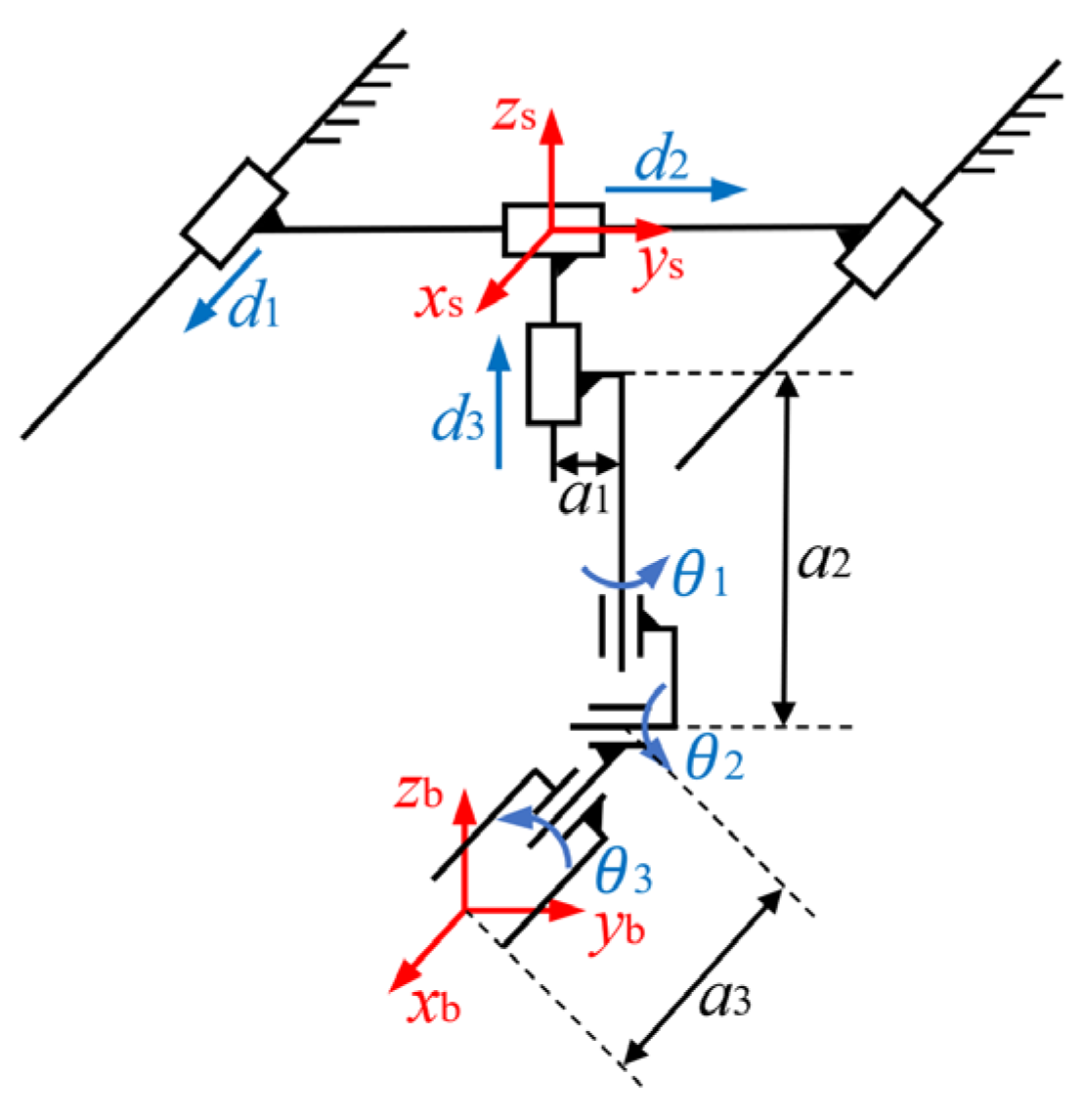
Figure 1. Schematic diagram of mechanism.
Machines 11 00046 g001
Figure 2. Schematic diagram of space station coordinates system.
Machines 11 00046 g002
Figure 3. Schematic diagram of robot coordinates system.
Machines 11 00046 g003
Figure 4. Virtual force sensor system block diagram.
Machines 11 00046 g004
Figure 5. System function block diagram of a single joint.
Machines 11 00046 g005
Figure 6. A single joint model of the virtual force sensor.
Machines 11 00046 g006
Figure 7. The pose following at the end effector of the robot. (a) the x component, (b) the y component, (c) the z component, (d) the ϕ component, (e) the θ component, and (f) the ψ component.
Machines 11 00046 g007aMachines 11 00046 g007b
Figure 8. The output of the virtual force sensor: (a) torque profiles and (b) force profiles.
Machines 11 00046 g008
Figure 9. The simulation model of two people cooperatively carrying objects.
Machines 11 00046 g009
Figure 10. Pose of virtual objects under the two-person collaboration: (a) the x component; (b) the y component; (c) the z component; (d) the ϕ component; (e) the θ component; and (f) the ψ component.
Machines 11 00046 g010
Figure 11. The output of the Virtual Force Sensor 1: (a) torque profiles and (b) force profiles.
Machines 11 00046 g011
Figure 12. Pose of the virtual object in a state of mutual antagonism: (a) the x component; (b) the y component; (c) the z component; (d) the ϕ component; (e) the θ component; and (f) the ψ component.
Machines 11 00046 g012
Figure 13. The output of the virtual force sensor in a state of mutual antagonism: (a) output torque profiles of the virtual force sensor 1; (b) output force profiles of the virtual force sensor 1; (c) output torque profiles of the virtual force sensor 2; and (d) output force profiles of the virtual force sensor 2.
Machines 11 00046 g013
Figure 14. The influence of Δ t 1 on the final position of the virtual object: (a) position profiles of the virtual object; and (b) output profiles of the virtual force sensor.
Machines 11 00046 g014
Figure 15. The influence of Δ t 2 on the final position of the virtual object: (a) position profiles of a virtual object and (b) output profiles of the virtual force sensor.
Machines 11 00046 g015
Figure 16. Pose of the VR handle and the virtual object in the first experiment: (a) the x component; (b) the y component; (c) the z component; (d) the ϕ component; (e) the θ component; and (f) the ψ component.
Machines 11 00046 g016
Figure 17. The output of the virtual force sensor in the first experiment: (a) output torque profiles of the virtual force sensor 1; (b) output force profiles of the virtual force sensor 1; (c) output torque profiles of the virtual force sensor 2; and (d) output force profiles of the virtual force sensor 2.
Machines 11 00046 g017
Figure 18. Pose of the VR handle and the virtual object in the second experiment: (a) the x component; (b) the y component; (c) the z component; (d) the ϕ component; (e) the θ component; and (f) the ψ component.
Machines 11 00046 g018
Figure 19. The output of the virtual force sensor in the second experiment: (a) output torque profiles of the virtual force sensor 1; (b) output force profiles of the virtual force sensor 1; (c) output torque profiles of the virtual force sensor 2; and (d) output force profiles of the virtual force sensor 2.
Machines 11 00046 g019
Table 1. Experimental setup.
No.Tester 1Tester 2 Δ t 1   Δ t 2
1stMove 1Still 20.020.5
2ndStillMove0.020.5
1 “Move” means that the tester initially moves and freely rotates the VR handle in space but remains stationary at the end of the experiment; 2 “Still” means the tester maintains the VR handle static during the test.
Table 2. Effect comparison of the virtual force sensor.
WorkRise Time 1Noise Value 2Solution Time 3
Proposed1.3795 s5.5 N0.1852 s
[10]1.4412 s200 N0.1190 s
1 Rise time is the time required for the position response of the virtual object to rise from 10% to 90% of the position command value; Due to the saturation effect of the virtual force sensor, this value is not very small; 2 Noise value refers to the difference between the maximum and the minimum value of the virtual force sensor output once the system reaches a steady state; 3 Solution time refers to the time required for the virtual force sensor to simulate one second; When the value is less than one second, the algorithm has real-time performance.
Disclaimer/Publisher’s Note: The statements, opinions and data contained in all publications are solely those of the individual author(s) and contributor(s) and not of MDPI and/or the editor(s). MDPI and/or the editor(s) disclaim responsibility for any injury to people or property resulting from any ideas, methods, instructions or products referred to in the content.