
Effective Energy Management Strategy with Model-Free DC-Bus Voltage Control for Fuel Cell/Battery/Supercapacitor Hybrid Electric Vehicle System

 , ,
, ,
Abstract
:1. Introduction
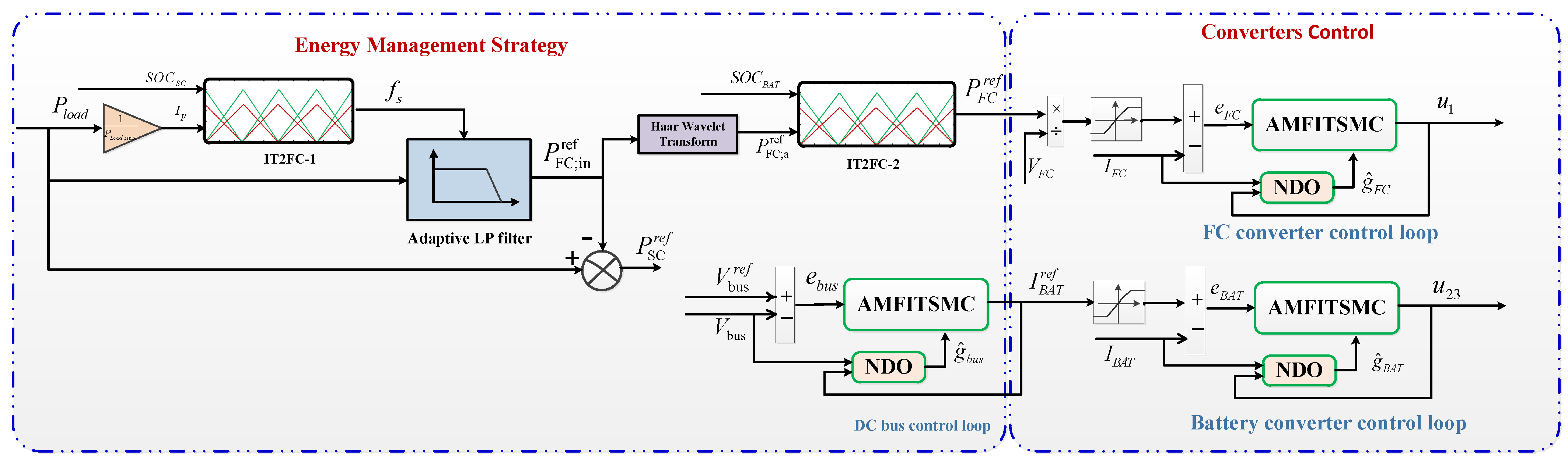
- A novel frequency-decoupling technique-based EMS is constructed using an adaptive LP filter, HWT, and IT2FC to determine the appropriate power sharing for different energy sources.
- Considering the dynamic characteristics of load power, an adaptive LP filter based on IT2FC is designed to adjust the output power of SC, maintain the SC state of charge within the predefined region, and ensure a fast response of load power during the vehicle acceleration and deceleration.
- In order to further improve the power performance, decrease the fuel consumption, and maintain the BAT state of charge, another IT2FC combined with HWT is established to provide optimal power of FC with low-frequency components.
- In order to avoid the requirement for accurate modeling and reduce the controller design difficulty, the ULM algorithm is employed to re-formulate the DC/DC power converters thanks to MFC theory, wherein the AMFITSMC based on NDO is proposed to regulate the DC bus voltage and currents of energy sources.
- Using the Lyapunov function, the stability analysis of the AMFITSMC method is investigated.
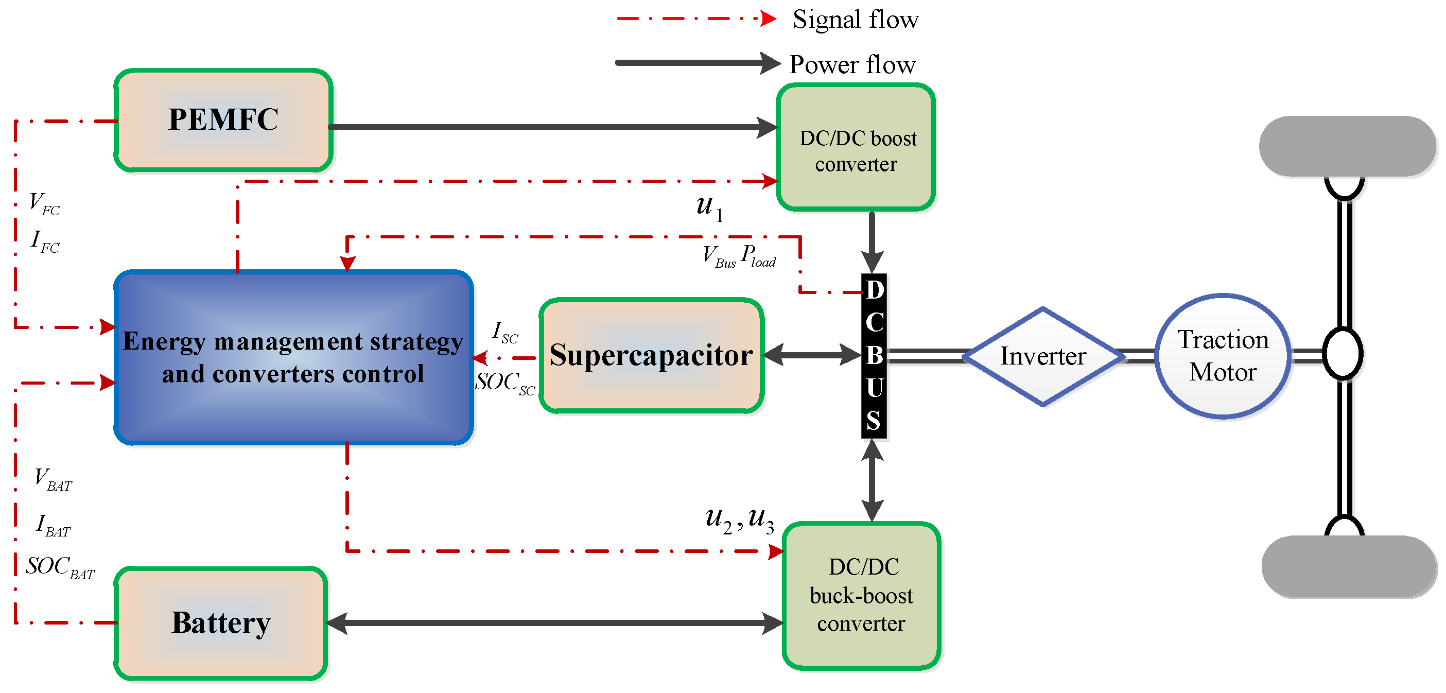
2. Description and Modeling of FCHEV
- High efficiency of the EMS to prolong the FC lifetime, decrease the fuel consumption, and improve the power performance;
- The state of charges of the BAT and SC should be maintained within the desired zones;
- Stabilize the DC bus voltage and power source’s currents with optimal control performance in the presence of different operating conditions;
- The stability of the whole controlled FCHEV system should be ensured.
2.1. Modeling of the Vehicle
2.2. Modeling of the Fuel Cell
2.3. Modelling of Battery
2.4. Modelling of Supercapacitor
2.5. Uni-Directional and Bi-Directional DC/DC Converters Modeling
3. Energy Management Strategy and Converters Control
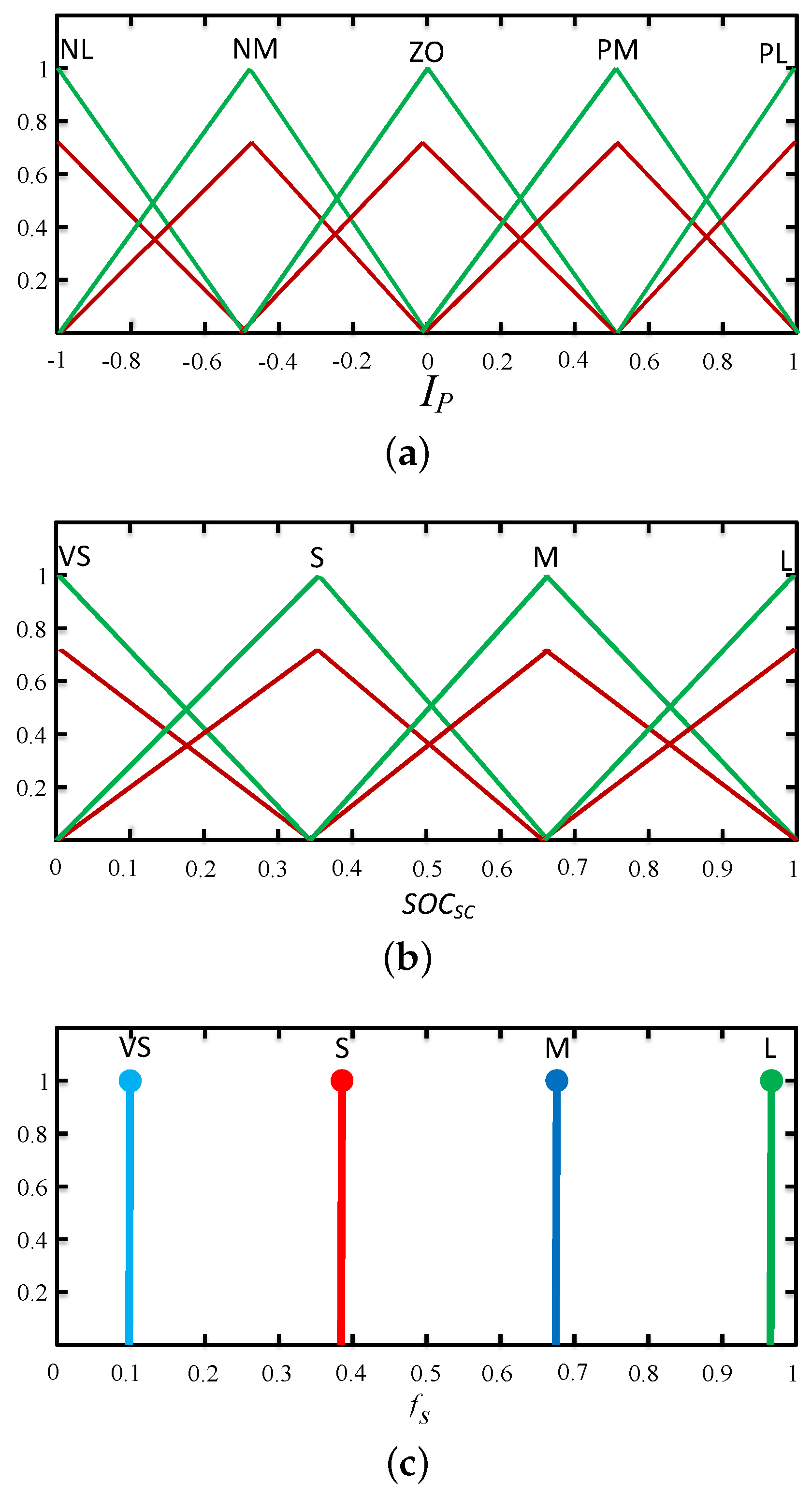
3.1. Design of Adaptive LP Filter Based on Interval Type–2 Fuzzy Controller
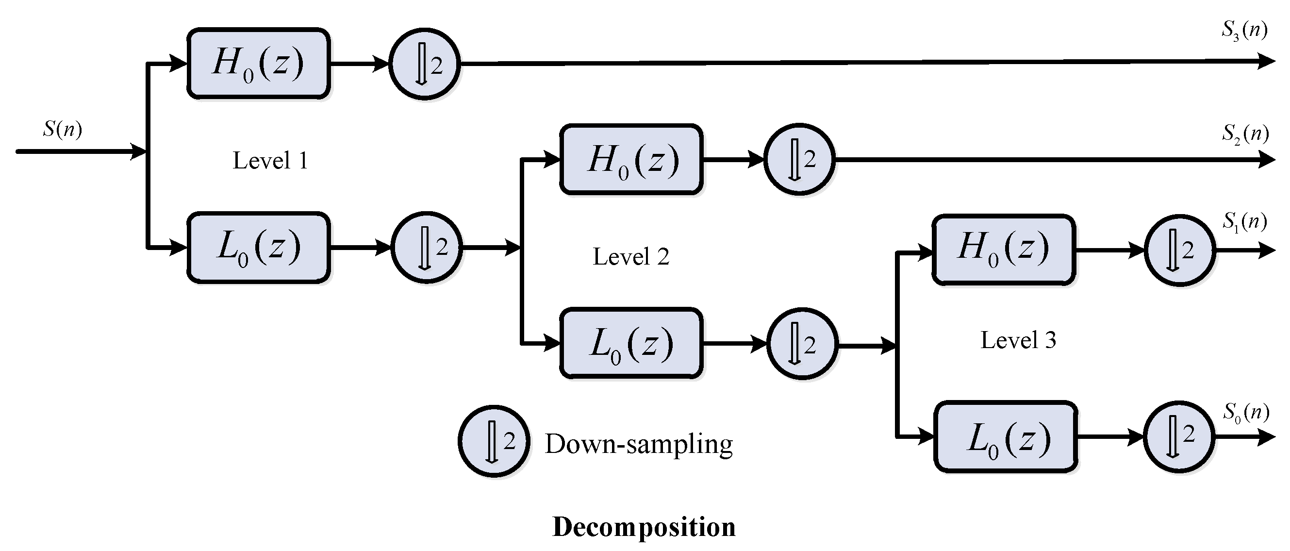
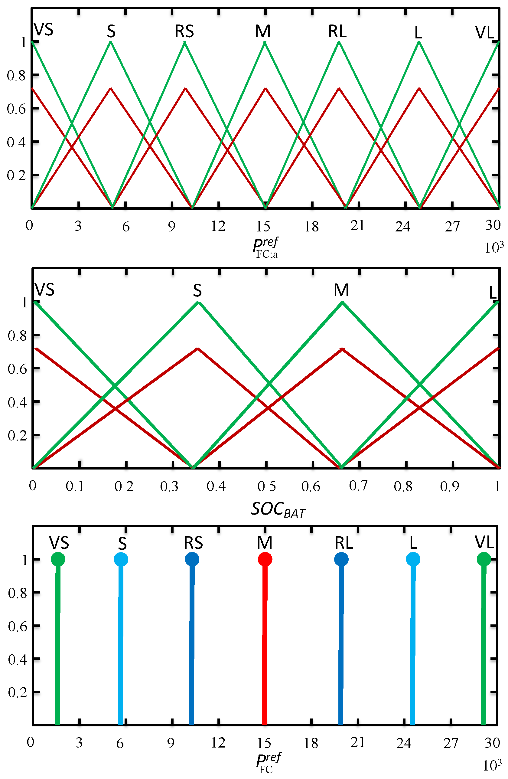
3.2. Design of Power Sharing Algorithm Using HWT and IT2FC–2
3.3. Adaptive Model-Free Integral Terminal Sliding Mode Control Using Nonlinear Disturbance Observer
3.3.1. NDO-iPI Design
Ultra-Local Model (ULM) Algorithm
Nonlinear Disturbance Observer (NDO) Design
3.3.2. AMFITSMC Design
4. Simulation Results
5. Conclusions
Author Contributions
Funding
Data Availability Statement
Acknowledgments
Conflicts of Interest
Abbreviations and Symbols
| FC | Fuel cell |
| ESS | Energy storage systems |
| BAT | battery |
| SC | Supercapacitor |
| FCHEV | Fuel cell hybrid Electric vehicle |
| EMS | Energy management strategy |
| HWT | Harr wavelet transform |
| IT2FC | Interval type-2 fuzzy controller |
| ULM | Ultra-local model |
| AMFITSMC | Adaptive model-free integral terminal sliding mode control |
| NDO | Nonlinear disturbance observer |
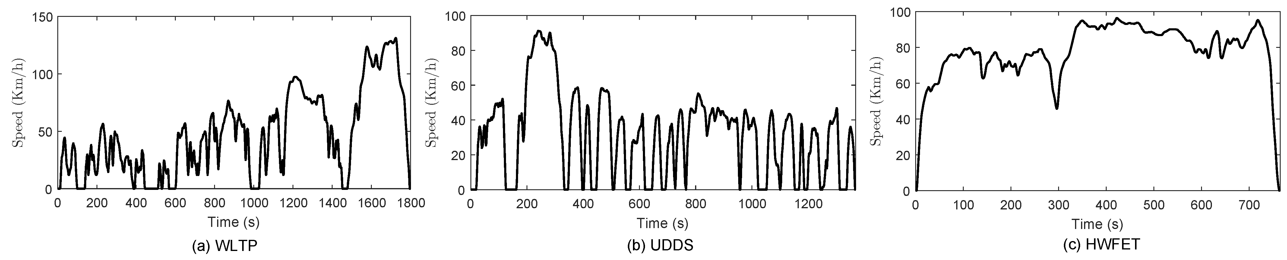
| WLTP | Worldwide Harmonised Light Vehicles Test Procedure |
| UDDS | Urban Dynamometer Driving Schedule |
| HWFET | Highway Fuel Economy Test |
| MPC | Model-predictive control |
| DP | Dynamic programing |
| PI | Proportional-integral |
| MPC | Model-free control |
| AO | Algebraic observer |
| TDE | Time-delay estimation |
| ESO | Extended state observer |
| SOC | State of charge |
| Vehicle speed | |
| Aerodynamic drag coefficient | |
| M | Vehicle mass |
| Vehicle frontal surface | |
| Rolling resistance coefficient | |
| Air density | |
| g | Gravitational acceleration |
| Inverter efficiency | |
| Fuel cell stack voltage | |
| Oxygen partial pressure | |
| Hydrogen partial pressure | |
| Fuel cell stack power | |
| Fuel cell current | |
| Hydrogen lower heating value | |
| Fuel cell equivalent hydrogen consumption | |
| Hydrogen molar mass | |
| Battery equivalent hydrogen consumption | |
| Supercapacitor equivalent hydrogen consumption | |
| Hydrogen chemical energy density | |
| Hydrogen price | |
| Electricity price | |
| Battery current | |
| Battery capacity | |
| Initial value of the battery state of charge | |
| Terminal voltage of supercapacitor | |
| Supercapacitor current | |
| Load current | |
| Load power | |
| Regulating frequency | |
| Mother wavelet, | |
| S | Input signal of HWT algorithm |
| Scalar parameter | |
| W | Wavelet coefficient |
| Reference power of fuel cell | |
| Reference current of battery | |
| Battery state of charge | |
| Supercapacitor state of charge |
References
- Abbaker, A.M.O.; Wang, H.; Tian, Y. Adaptive integral type-terminal sliding mode control for PEMFC air supply system using time delay estimation algorithm. Asian J. Control 2022, 24, 217–226. [Google Scholar] [CrossRef]
- Abbaker, A.M.O.; Wang, H.; Tian, Y. Enhanced model-free discrete time adaptive terminal sliding-mode control for SOFC power plant with input constraints. Arab. J. Sci. Eng. 2022, 47, 2851–2864. [Google Scholar]
- Chi, X.; Quan, S.; Chen, J.; Wang, Y.-X.; He, H. Proton exchange membrane fuel cell-powered bidirectional DC motor control based on adaptive sliding-mode technique with neural network estimation. Int. J. Hydrogen Energy 2020, 45, 20282–20292. [Google Scholar] [CrossRef]
- Li, Q.; Chen, W.; Liu, Z.; Li, M.; Ma, L. Development of energy management system based on a power sharing strategy for a fuel cell-battery-supercapacitor hybrid tramway. J. Power Sources 2015, 279, 267–280. [Google Scholar] [CrossRef]
- Dinh, T.X.; Thuy, L.K.; Tien, N.T.; Dang, T.D.; Ho, C.M.; Truong, H.V.A.; Dao, H.V.; Do, T.C.; Ahn, K.K. Modeling and Energy Management Strategy in Energetic Macroscopic Representation for a Fuel Cell Hybrid Electric Vehicle. J. Drive Control. 2019, 16, 11. [Google Scholar]
- Fu, Z.; Li, Z.; Si, P.; Tao, F. A hierarchical energy management strategy for fuel cell/battery/supercapacitor hybrid electric vehicles. Int. J. Hydrogen Energy 2019, 44, 22146–22159. [Google Scholar] [CrossRef]
- Li, H.; Ravey, A.; N’Diaye, A.; Djerdir, A. A novel equivalent consumption minimization strategy for hybrid electric vehicle powered by fuel cell, battery and supercapacitor. J. Power Sources 2018, 395, 262–270. [Google Scholar] [CrossRef]
- Peng, F.; Zhao, Y.; Li, X.; Liu, Z.; Chen, W.; Liu, Y.; Zhou, D. Development of master-slave energy management strategy based on fuzzy logic hysteresis state machine and differential power processing compensation for a PEMFC-LIB-SC hybrid tramway. Appl. Energy 2017, 206, 346–363. [Google Scholar] [CrossRef]
- Piraino, F.; Fragiacomo, P. A multi-method control strategy for numerically testing a fuel cell-battery-supercapacitor tramway. Energy Convers. Manag. 2020, 225, 113481. [Google Scholar] [CrossRef]
- Dang, T.D.; Do, T.C.; Truong, H.V.A.; Ho, C.M.; Dao, H.V.; Xiao, Y.Y.; Jeong, E.; Ahn, K.K. Design, Modeling and Analysis of a PEM Fuel Cell Excavator with Supercapacitor/Battery Hybrid Power Source. J. Drive Control. 2019, 16, 45–53. [Google Scholar]
- Li, T.; Liu, H.; Zhao, D.; Wang, L. Design and analysis of a fuel cell supercapacitor hybrid construction vehicle. Int. J. Hydrogen Energy 2016, 41, 12307–12319. [Google Scholar] [CrossRef]
- Fagundes, T.A.; Fuzato, G.H.F.; Ferreira, P.G.B.; Biczkowski, M.; Machado, R.Q. Fuzzy Controller for Energy Management and SoC Equalization in DC Microgrids Powered by Fuel Cell and Energy Storage Units. IEEE J. Emerg. Sel. Top. Ind. Electron. 2022, 3, 90–100. [Google Scholar] [CrossRef]
- Aguiar, C.R.D.; Fuzato, G.H.F.; Machado, R.Q.; Guerrero, J.M. An Adaptive Power Sharing Control for Management of DC Microgrids Powered by Fuel Cell and Storage System. IEEE Trans. Ind. Electron. 2020, 67, 3726–3735. [Google Scholar] [CrossRef]
- Wilberforce, T.; El-Hassan, Z.; Khatib, F.; Makky, A.A.; aroutaji, A.; Carton, J.G.; labi, A.G. Developments of electric cars and fuel cell hydrogen electric cars. Int. J. Hydrogen Energy 2017, 42, 25695–25734. [Google Scholar] [CrossRef]
- Omer, A.A.M.; Wang, H.P.; Yang, T. Bat-optimized fuzzy controller with fractional order adaptive super-twisting sliding mode control for fuel cell/battery hybrid power system considering fuel cell degradation. J. Renew. Sustain. Energy 2021, 13, 044701. [Google Scholar]
- Song, Z.; Hofmann, H.; Li, J.; Han, X.; Ouyang, M. Optimization for a hybrid energy storage system in electric vehicles using dynamic programing approach. Energy 2015, 139, 151–162. [Google Scholar] [CrossRef]
- Wang, Y.; Li, X.; Wang, L.; Sun, Z. Multiple-grained velocity prediction and energy management strategy for hybrid propulsion systems. J. Energy Storage 2019, 26, 100950. [Google Scholar] [CrossRef]
- Ettihir, K.; Higuita-Cano, M.; Boulon, L.; Agbossou, K. Design of an adaptive EMS for fuel cell vehicles. Int. J. Hydrogen Energy 2017, 42, 1481–1489. [Google Scholar] [CrossRef]
- Herrera, V.I.; Gaztanaga, H.; Milo, A.; Saez-de-Ibarra, A.; Etxeberria-Otadui, I.; Nieva, T. Optimal energy management and sizing of a battery-supercapacitor-based light rail vehicle with a multiobjective approach. IEEE Trans. Ind. Appl. 2016, 52, 3367–3377. [Google Scholar] [CrossRef]
- Yuan, J.N.; Yang, L.; Chen, Q. Intelligent energy management strategy based on hierarchical approximate global optimization for plug-in fuel cell hybrid electric vehicles. Int. J. Hydrogen Energy 2018, 43, 8063–8078. [Google Scholar] [CrossRef]
- Flah, A.; Mahmoudi, C. A novel energy optimization approach for electrical vehicles in a smart city. Energies 2019, 12, 929. [Google Scholar]
- Wang, Y.; Sun, Z.; Chen, Z. Development of energy management system based on a rule-based power distribution strategy for hybrid power sources. Energy 2019, 175, 1055–1066. [Google Scholar] [CrossRef]
- Marzougui, H.; Amari, M.; Kadri, A.; Bacha, F.; Ghouili, J. Energy management of fuel cell/battery/ultracapacitor in electrical hybrid vehicle. Int. J. Hydrogen Energy 2017, 42, 8857–8869. [Google Scholar] [CrossRef]
- Xun, Q.; Lundberg, S.; Liu, Y. Design and experimental verification of a fuel cell/supercapacitor passive configuration for a light vehicle. J. Energy Storage 2021, 33, 102110. [Google Scholar] [CrossRef]
- Taskin, A.; Kumbasar, T. An open source Matlab/Simulink toolbox for interval type-2 fuzzy logic systems. In Proceedings of the 2015 IEEE Symposium Series on Computational Intelligence, Cape Town, South Africa, 7–10 December 2015; IEEE: Piscataway, NJ, USA, 2015; pp. 1561–1568. [Google Scholar]
- Wang, H.; Liu, S.; Yang, X. Adaptive neural control for nonstrict-feedback nonlinear systems with input delay. Inf. Sci. 2020, 514, 605–616. [Google Scholar] [CrossRef]
- Hemi, H.; Ghouili, J.; Cheriti, A. A real time fuzzy logic power management strategy for a fuel cell vehicle. Energy Convers. Manag. 2014, 80, 63–70. [Google Scholar] [CrossRef]
- Snoussi, J.; BenElghali, S.; Benbouzid, M.; Mimouni, M.F. Auto-Adaptive Filtering-Based Energy Management Strategy for Fuel Cell Hybrid Electric Vehicles. Energies 2018, 11, 2118. [Google Scholar] [CrossRef]
- Song, K.; Chen, H.; Wen, P.; Zhang, T.; Zhang, B.; Zhang, T. A comprehensive evaluation framework to evaluate energy management strategies of fuel cell electric vehicles. Electrochim. Acta 2018, 292, 960–973. [Google Scholar] [CrossRef]
- Javier, S.M.; Jerome, M.; Fabien, H.; Daniel, H.; Marie-Cecile, P.; Robert, I.J.; Michel, A. Experimental validation of a type-2 fuzzy logic controller for energy management in hybrid electrical vehicles. Eng. Appl. Artif. Intell. 2013, 26, 1772–1779. [Google Scholar]
- Trinh, H.-A.; Phan, V.-D.; Truong, H.-V.-A.; Ahn, K.K. Energy Management Strategy for PEM Fuel Cell Hybrid Power System Considering DC Bus Voltage Regulation. Electronics 2022, 11, 2722. [Google Scholar] [CrossRef]
- Aouzellag, H.; Ghedamsi, K.; Aouzellag, D. Energy management and fault tolerant control strategies for fuel cell/ultra-capacitor hybrid electric vehicles to enhance autonomy, efficiency and life time of the fuel cell system. Int. J. Hydrogen Energy 2015, 40, 7204–7213. [Google Scholar] [CrossRef]
- Fadil, H.E.; Giri, F.; Guerrero, J.M.; Tahri, A. Modeling and Nonlinear Control of a Fuel Cell/Supercapacitor Hybrid Energy Storage System for Electric Vehicles. IEEE Trans. Veh. Technol. 2014, 63, 3011–3018. [Google Scholar] [CrossRef]
- Depature, C.; Lhomme, W.; Sicard, P.; Bouscayrol, A.; Boulon, L. Real-Time Backstepping Control for Fuel Cell Vehicle Using Supercapacitors. IEEE Trans. Veh. Technol. 2017, 67, 306–314. [Google Scholar] [CrossRef]
- Xu, D.; Liu, Q.; Yan, W.; Yang, W. Adaptive Terminal Sliding Mode Control for Hybrid Energy Storage Systems of Fuel Cell, Battery and Supercapacitor. IEEE Access 2019, 7, 29295–29303. [Google Scholar] [CrossRef]
- Russo, A.; Cavallo, A. stability and control for More Electric Aircraft application. In Proceedings of the 2020 European Control Conference (ECC), St. Petersburg, Russia, 12–15 May 2020; pp. 1909–1914. [Google Scholar] [CrossRef]
- Russo, A.; Canciello, G.; Cavallo, A. Generalized Super-Twisting control of a Dual Active Bridge for More Electric Aircraft. In Proceedings of the 2021 European Control Conference (ECC), Delft, The Netherlands, 29 June–2 July 2021; pp. 1610–1615. [Google Scholar] [CrossRef]
- Benmouna, A.; Becherif, M.; Depernet, D.; Depature, C.; Boulon, L. Nonlinear control and optimization of hybrid electrical vehicle under sources limitation constraints. Int. J. Hydrogen Energy 2020, 45, 11255–11266. [Google Scholar] [CrossRef]
- Abbaker, A.O.; Wang, H.P.; Tian, Y. Voltage control of solid oxide fuel cell power plant based on intelligent proportional integral-adaptive sliding mode control with anti-windup compensator. Trans. Inst. Meas. Control 2020, 42, 116–130. [Google Scholar] [CrossRef]
- Mustafa, G.I.Y.; Wang, H.P.; Tian, Y. Model-free adaptive fuzzy logic control for a half-car active suspension system. Stud. Inform. Control 2019, 28, 13–24. [Google Scholar] [CrossRef]
- Pereira, G.; Augusto-Angelico, B. Model-free control of mechatronic systems based on algebraic estimation. Asian J. Control 2022, 24, 1575–1584. [Google Scholar] [CrossRef]
- Haddar, M.; Bouslema, M.; Caglar-Baslamisli, S.; Chaari, F.; Haddar, M. Improving the ride comfort of full car model with a decoupling intelligent model free controller. Proc. Inst. Mech. Eng. Part D J. Automob. Eng. 2022, OnlineFirst. [Google Scholar] [CrossRef]
- Suh, K.W. Modeling, Analysis and Control of Fuel Cell Hybrid Power Systems. Ph.D. Thesis, University of Michigan, Ann Arbor, MI, USA, 2006. [Google Scholar]
- Pukrushpan, J.T.; Stefanopoulou, A.G.; Peng, H. Control of fuel cell breathing. IEEE Control. Syst. Mag. 2004, 24, 30–46. [Google Scholar]
- Abdalla, M.A.A.; Min, W.; Mohammed, O.A.A. Two-Stage Energy Management Strategy of EV and PV Integrated Smart Home to Minimize Electricity Cost and Flatten Power Load Profile. Energies 2020, 13, 6387. [Google Scholar] [CrossRef]
- Zhang, Y.; Zhang, C.; Huang, Z.; Xu, L.; Liu, Z.; Liu, M. Real-time energy management strategy for fuel cell range extender vehicles based on nonlinear control. IEEE Trans. Transp. Electrif. 2019, 5, 1294–1305. [Google Scholar] [CrossRef]
- Zhang, G.; Li, Q.; Chen, W.; Meng, X.; Deng, H. A coupled power-voltage equilibrium strategy based on droop control for fuel cell/battery/supercapacitor hybrid tramway. Int. J. Hydrogen Energy 2019, 44, 19370–19383. [Google Scholar] [CrossRef]
- Zhang, R.; Tao, J.; Zhou, H. Fuzzy optimal energy management for fuel cell and supercapacitor systems using neural network based driving pattern recognition. IEEE Trans. Fuzzy Syst. 2019, 27, 45–57. [Google Scholar] [CrossRef]
- Armghan, H.; Ahmad, I.; Ali, N.; Munir, M.F.; Khan, S.; Armghan, A. Nonlinear Controller Analysis of Fuel Cell-Battery-Ultracapacitor-based Hybrid Energy Storage Systems in Electric Vehicles. Arab. J. Sci. Eng. 2018, 43, 3123–3133. [Google Scholar] [CrossRef]
- Erdinc, O.; Vural, B.; Uzunoglu, M. A wavelet-fuzzy logic based energy management strategy for a fuel cell/battery/ultra-capacitor hybrid vehicular power system. J. Power Sources 2009, 194, 369–380. [Google Scholar] [CrossRef]
- Pan, M.; Yan, J.; Tu, Q.; Jiang, C. Fuzzy control and wavelet transform-based energy management strategy design of a hybrid tracked bulldozer. J. Intell. Fuzzy Syst. 2015, 29, 2565–2574. [Google Scholar]
- Fliess, M.; Join, C. Model-free control. Int. J. Control 2013, 86, 2228–2252. [Google Scholar] [CrossRef]
- Abbaker, A.M.O.; Wang, H.P.; Tian, Y. Robust Model-Free Adaptive Interval Type-2 Fuzzy Sliding Mode Control for PEMFC System Using Disturbance Observer. Int. J. Fuzzy Syst. 2020, 22, 2188–2203. [Google Scholar] [CrossRef]
- Wipke, K.B.; Cuddy, M.R.; Burch, S.D. ADVISOR 2.1: A user-friendly advanced powertrain simulation using a combined back-ward/forward approach. IEEE Trans. Veh. Technol. 1999, 48, 1751–1761. [Google Scholar]
- Li, Q.; Yang, H.; Han, Y.; Li, M.; Chen, W. A state machine strategy based on droop control for an energy management system of PEMFC-battery-supercapacitor hybrid tramway. Int. J. Hydrogen Energy 2016, 41, 16148–16159. [Google Scholar] [CrossRef]


| NL | NM | ZO | PM | PL | ||
|---|---|---|---|---|---|---|
| VS | VS | VS | L | M | S | |
| S | S | S | L | M | VS | |
| M | M | M | L | S | VS | |
| L | L | L | L | S | VS |
| VS | S | RS | M | RL | L | VL | ||
|---|---|---|---|---|---|---|---|---|
| VS | RS | M | RL | L | VL | VL | VL | |
| S | S | RS | M | RL | L | VL | VL | |
| M | VS | S | RS | M | RL | L | VL | |
| L | VS | VS | S | RS | M | RL | L |
| Component | Parameter | Values |
|---|---|---|
| Vehicle | Aerodynamic drag coefficient | 0.275 |
| Air density | 1.23 kg·m | |
| Vehicle frontal area | 2.688 m | |
| Vehicle total mass M | 1550 kg | |
| Rolling resistance coefficient | 0.014 | |
| Fuel cell | Maximum current | 300 A |
| Rated voltage | 265 V | |
| Maximum net power | 30 kW | |
| Battery | Rated capacity | 20 Ah |
| 90% | ||
| 30% | ||
| Supercapacitor | Storage capacity | 160 Wh |
| 90% | ||
| 40% | ||
| DC-link bus | Rated voltage | 420 V |
| Converters | Inductor , | 2 × 10 H |
| Resistance , | 0.1 | |
| Capacitor | 0.008 F |
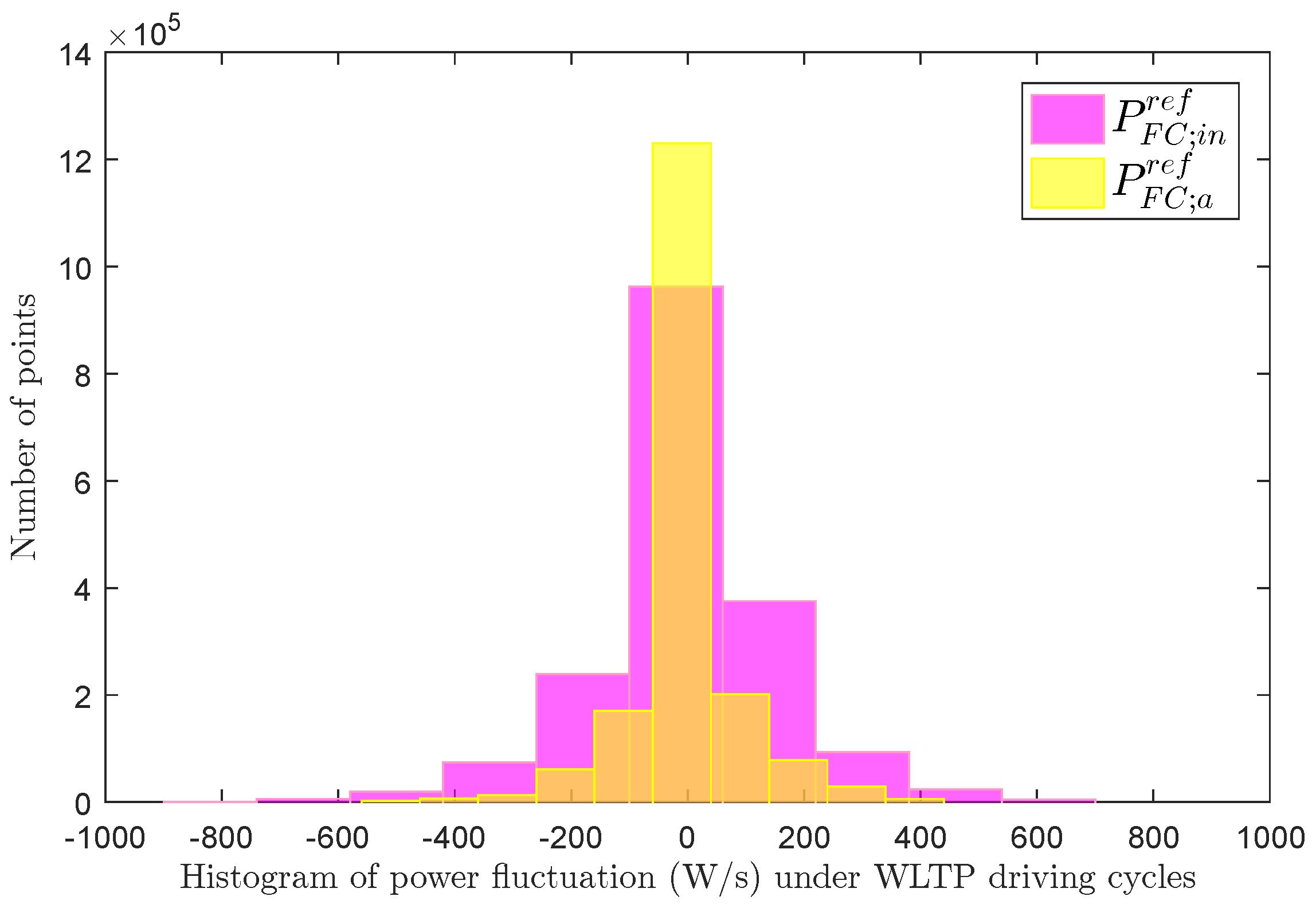
| EMS | FC Power Fluctuation (W/s) | Consumption (L) | Final Value of | ||||||
|---|---|---|---|---|---|---|---|---|---|
| WLTP | UDDS | HWFET | WLTP | UDDS | HWFET | WLTP | UDDS | HWFET | |
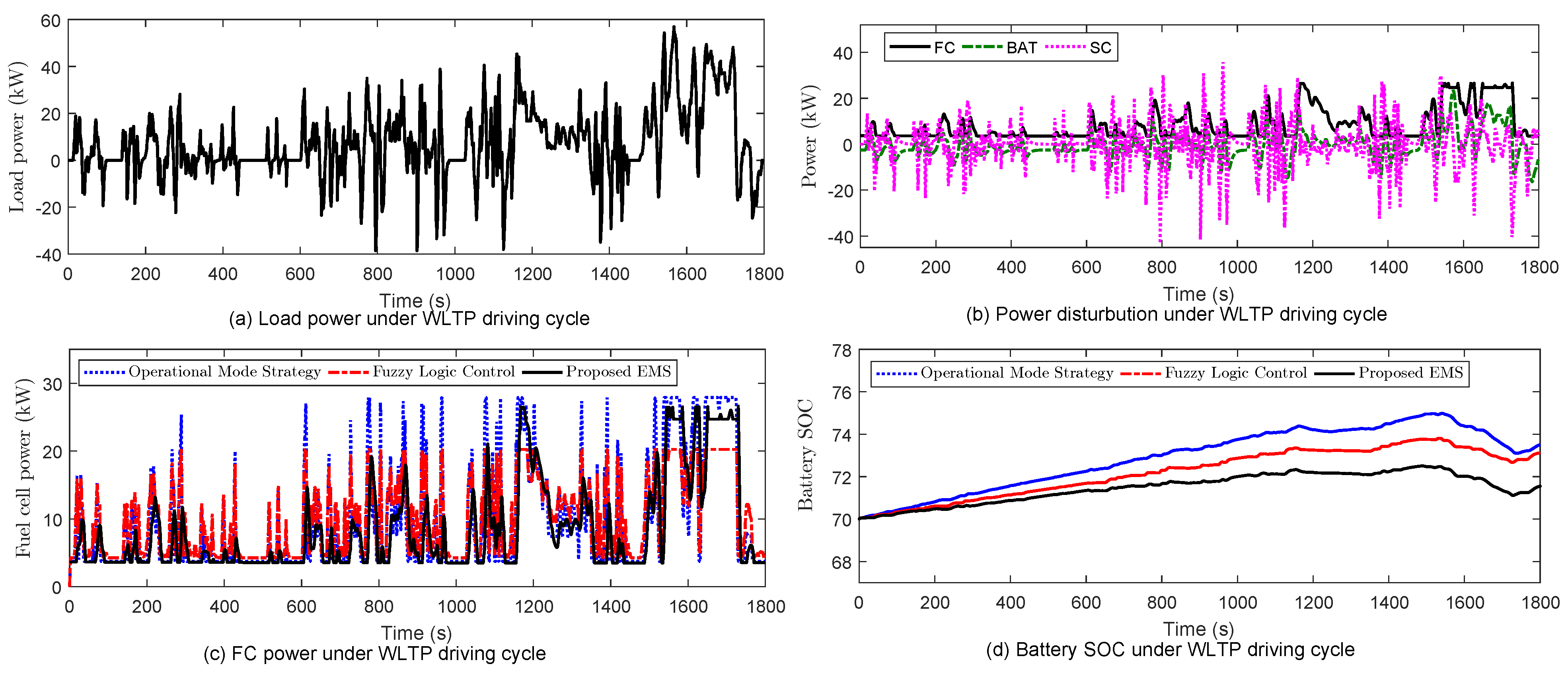
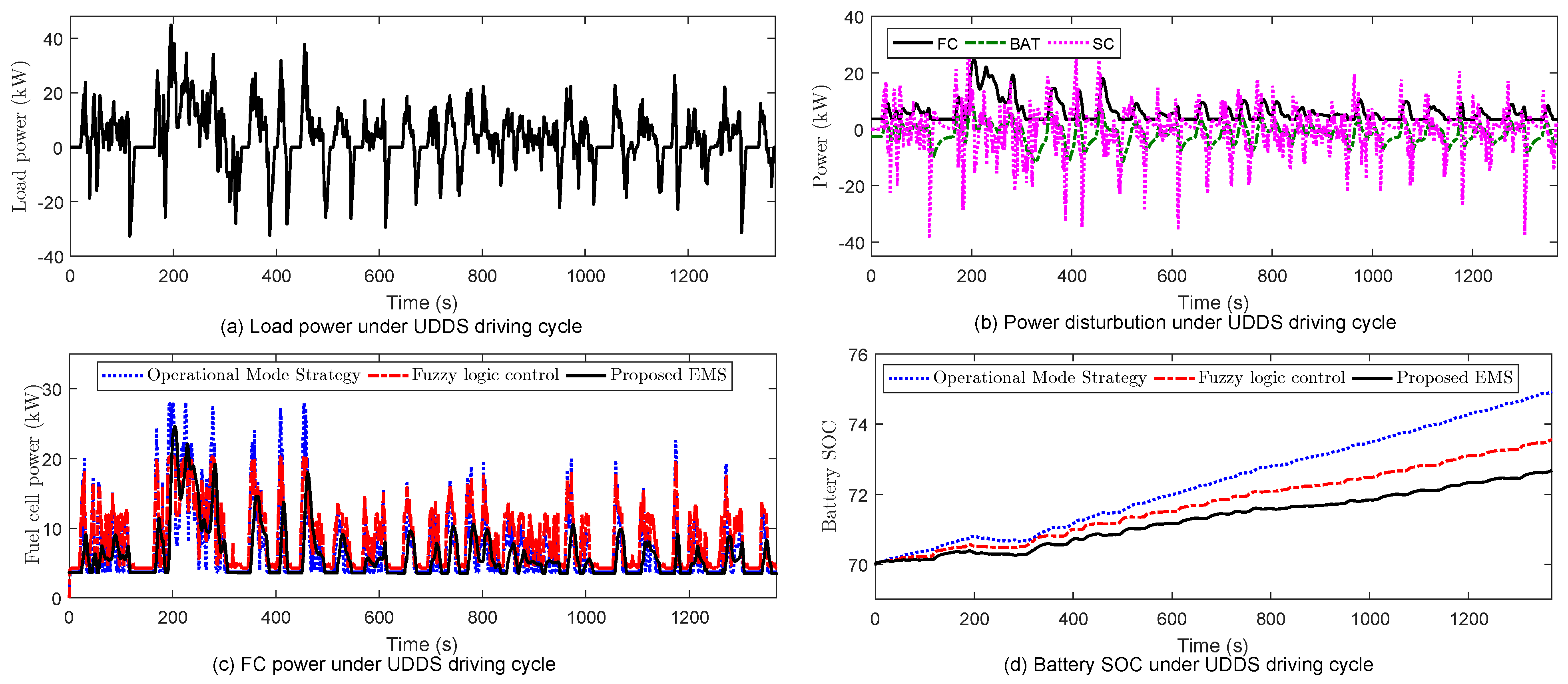
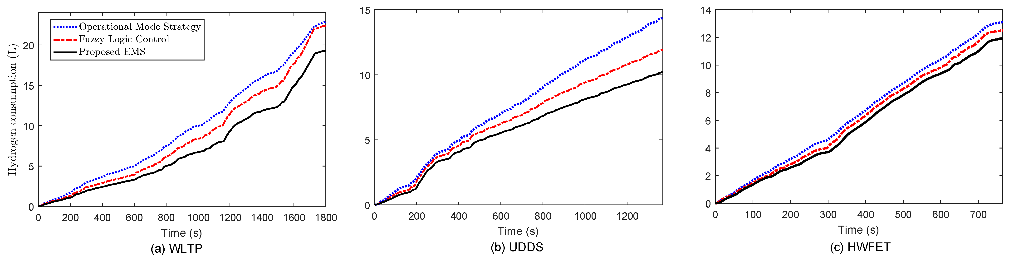
| Operational mode strategy | ±1000 | ±1000 | ±900 | 22.82 | 14.38 | 13.15 | 73.5 | 74.95 | 70.6 |
| Fuzzy logic control | ±600 | ±600 | ±500 | 22.4 | 11.85 | 12.5 | 73.35 | 73.5 | 70.38 |
| Proposed EMS | ±300 | ±300 | ±250 | 19.25 | 10.21 | 11.85 | 71.52 | 72.6 | 70.05 |
Disclaimer/Publisher’s Note: The statements, opinions and data contained in all publications are solely those of the individual author(s) and contributor(s) and not of MDPI and/or the editor(s). MDPI and/or the editor(s) disclaim responsibility for any injury to people or property resulting from any ideas, methods, instructions or products referred to in the content. |
© 2023 by the authors. Licensee MDPI, Basel, Switzerland. This article is an open access article distributed under the terms and conditions of the Creative Commons Attribution (CC BY) license (https://creativecommons.org/licenses/by/4.0/).
Share and Cite
Mohammed, O.A.A.; Peng, L.; Hamid, G.H.A.; Ishag, A.M.; Abdalla, M.A.A. Effective Energy Management Strategy with Model-Free DC-Bus Voltage Control for Fuel Cell/Battery/Supercapacitor Hybrid Electric Vehicle System. Machines 2023, 11, 944. https://doi.org/10.3390/machines11100944
Mohammed OAA, Peng L, Hamid GHA, Ishag AM, Abdalla MAA. Effective Energy Management Strategy with Model-Free DC-Bus Voltage Control for Fuel Cell/Battery/Supercapacitor Hybrid Electric Vehicle System. Machines. 2023; 11(10):944. https://doi.org/10.3390/machines11100944
Chicago/Turabian StyleMohammed, Omer Abbaker Ahmed, Lingxi Peng, Gomaa Haroun Ali Hamid, Ahmed Mohamed Ishag, and Modawy Adam Ali Abdalla. 2023. "Effective Energy Management Strategy with Model-Free DC-Bus Voltage Control for Fuel Cell/Battery/Supercapacitor Hybrid Electric Vehicle System" Machines 11, no. 10: 944. https://doi.org/10.3390/machines11100944
APA StyleMohammed, O. A. A., Peng, L., Hamid, G. H. A., Ishag, A. M., & Abdalla, M. A. A. (2023). Effective Energy Management Strategy with Model-Free DC-Bus Voltage Control for Fuel Cell/Battery/Supercapacitor Hybrid Electric Vehicle System. Machines, 11(10), 944. https://doi.org/10.3390/machines11100944