Article

Effect of Vibrotactile Feedback on the Control of the Interaction Force of a Supernumerary Robotic Arm

1
NeXT Lab Neurophysiology and Neuroengineering of Human Technology Interaction, Università Campus Bio-Medico, 00128 Rome, Italy
2
School of Engineering, Newcastle University, Newcastle upon Tyne NE1 7RU, UK
3
Institute for Intelligent Systems and Robotics (ISIR), Sorbonne Université, CNRS, INSERM, 75005 Paris, France
*
Authors to whom correspondence should be addressed.
Machines 2023, 11(12), 1085; https://doi.org/10.3390/machines11121085
Submission received: 10 November 2023 / Revised: 1 December 2023 / Accepted: 7 December 2023 / Published: 13 December 2023
(This article belongs to the Special Issue Recent Advances in Medical Robotics)

Abstract

:
Supernumerary robotic limbs are mainly designed to augment the physical capabilities of able-bodied individuals, in a wide range of contexts from body support to surgery. When they are worn as wearable devices, they naturally provide inherent feedback due to the mechanical coupling with the human body. The user can, thus, perceive the interaction with the environment by relying on a combination of visual and inherent feedback. However, these can be inefficient in accomplishing complex tasks, particularly in the case of visual occlusion or variation in the environment stiffness. Here, we investigated whether, in a force-regulation task using a wearable supernumerary robotic arm (SRA), additional vibrotactile feedback can increase the control performance of participants compared to the inherent feedback. Additionally, to make the scenario more realistic, we introduced variations in the SRA’s kinematic posture and in the environment stiffness. Notably, our findings revealed a statistically significant improvement in user performance over all the evaluated metrics while receiving additional vibrotactile feedback. Compared to inherent feedback alone, the additional vibrotactile feedback allowed participants to exert the required force faster (p < 0.01), to maintain it for longer (p < 0.001), and with lower errors (p < 0.001). No discernible effects related to the SRA’s posture or environment stiffness were observed. These results proved the benefits of providing the user with additional vibrotactile feedback to convey the SRA’s force during interaction tasks.

1. Introduction

Supernumerary robotic limbs (SRLs) are robotic manipulators, often wearable, designed to achieve human motor augmentation, i.e., to enhance the motor abilities of able-bodied individuals by including supernumerary robotic arms (SRAs), legs (SRLGs), or fingers (SRFs) into their motor control. The engineering applications of SRLs are several and range from compensation or function restoration in patients with physical limitations to the actual augmentation of healthy individuals beyond human physical abilities.
The main application scenarios can be summarized into three categories [1]: holding and manipulating objects, enhancing the workspace, and balancing and stabilizing the user. For example, Davenport et al. [2] and Llorens-Bonilla et al. [3] realized an SRA to assist the operator in aircraft assembly tasks such as holding objects, lifting weights, and compensating for the disturbance caused by drilling. Enhancing the workspace implies interacting with objects either outside of the human-reachable workspace or while the hands are occupied, such as in overhead tasks (e.g., SRAs mounted on the user’s shoulders for ceiling work scenarios [4,5,6]). Indeed, the use of SRAs helps avoid massive injuries and long-term fatigue often caused by overhead tasks and could lead to increased overall workplace productivity, safety, and effectiveness. The latter application is to balance and support the human body and reduce human fatigue, such as in [7,8], where Parietti et al. designed a waist-mounted SRA to minimize the torque exerted on the human joints, or in [9,10], where they realized two additional robotic legs, attached to a backpack-like harness providing balancing assistance, a reduction of the joint load on human walking, and human support in special postures.
In all these applications, particularly when concerning the SRAs, the operator does not have direct information on the robot’s interaction with the environment, except visual feedback. However, this might be insufficient to complete complex tasks, especially when vision is occluded or during contact with environments that are not compliant, i.e., where the force application does not produce a visible deformation.
In contrast, haptic feedback would allow the user to feel such interaction force, eventually conveyed through a different type of sensation.
When SRLs are worn as wearable devices, they naturally provide haptic feedback on the user body, which perceives not only the presence of the robot, but also part of the interaction forces that arise from the contact with the environment, through the mechanical coupling between the SRL and the human body. This is called inherent feedback as it provides the individual with intrinsic information naturally available when wearing the device.
This type of feedback was recently investigated by Guggenheim and Asada [11], who demonstrated that the inherent feedback provided by an SRA on the user’s lower back would be sufficient for the user to control the output force at the SRA end-effector. Nonetheless, this result was obtained with a rigid one-degree-of-freedom (DoF) robotic arm and an optimized fixation to the operator’s body in a simplified task with the robot end-effector being attached to the environment. The inherent feedback is sensitive to the variability of several parameters though, such as the mechanical characteristics of the environment (i.e., rigid versus soft contact interfaces) or the SRA itself, such as its kinematic posture or its joint compliance.
Considering more-realistic scenarios with heavy, multi-DoF, re-configurable robots and intermittent interaction with the environment, the question of which benefits can be obtained by providing the operator with additional haptic feedback compared to inherent feedback alone remains open.
Several studies have already demonstrated the usefulness of additional haptic feedback in the case of an SRF [12,13,14,15,16] provided by means of electro- or vibrotactile stimulation to convey the force or position of the extra robotic limb, respectively.
However, while the use of haptic feedback interfaces is rather common in prostheses and exoskeletons [17,18,19,20,21,22,23], as well as in supernumerary robotic fingers, it is still unexplored in SRAs. Only M.H.D. Yamen Saraiji et al. [24] investigated feedback interfaces for SRAs, providing two feet-controlled artificial arms with position and torque feedback to the sole of the feet. The system worked reasonably well in pointing tasks and, in some cases, seemed to succeed in temporarily eliciting the feeling of having two additional arms.
On the other side, a few studies have investigated the use of haptic feedback on non-wearable SRAs. Refs. [25,26,27] provided vibrotactile feedback on the leg of the user proportional to either the position of the end-effector or the joints’ angles or torques, whereas [28] used pressure feedback on the user’s feet to convey the end-effector contact force. However, these studies employed non-wearable robotic arms that, thus, do not provide inherent feedback. A comprehensive review of the impact of feedback on control of SRLs is out of the scope of the present work, but more information can be found in [29].
The goal of the present study was to investigate, for the first time, the effect on the control performance of an additional vibrotactile feedback concerning the SRA interaction force and test whether this feedback can lead to better performance compared to the inherent feedback of the wearable SRA. In fact, we believe that relaying simple additional artificial sensory feedback to provide users with the rich sensation of the force exerted by an SRA is essential for bringing human sensorimotor augmentation to the next level, in which humans can effortlessly control SRAs as part of their own bodies. This work constitutes a novelty in the field of human augmentation since, to the best of our knowledge, no other work has directly compared the contributions of inherent and supplementary vibrotactile feedback provided by a wearable SRA.
In particular, we assessed in a simplified, but realistic scenario of force regulation with a wearable SRA the usefulness of relaying through supplementary vibrotactile feedback information about the force applied by the SRA when interacting with the environment. The objective of the task was to assess the ability of the user to exert a requested amount of force with the SRA’s end-effector. In particular, we investigated how the additional feedback affects performance compared to inherent feedback only, with different robot postures and environment stiffness.
We decided to adopt as the feedback modality the vibrotactile one because it is non-invasive and suitable for unobtrusive integration, allowing for comfortable wear without impeding the concurrent use of the SRA. This choice was also supported by the demonstrated effectiveness of vibrotactile feedback in various applications, including SRFs [13,14,15,16], robotic arms [25,26,27], and prosthesis [17,18,19,23], further supporting its suitability for our specific scientific investigation.
In the following section, the materials and methods used will be deepened, with specific attention on the experimental setup in Section 2.1, the vibrotactile feedback and data processing in Section 2.2, the experimental protocol in Section 2.3, and the data analysis in Section 2.4. Later on, in Section 3, the results will be presented, focusing on the effect of the feedback, the effect of the variation of the environmental parameters, and the subjective perception of the participants. To conclude, the discussions and conclusions are presented in Section 4.

2. Materials and Methods

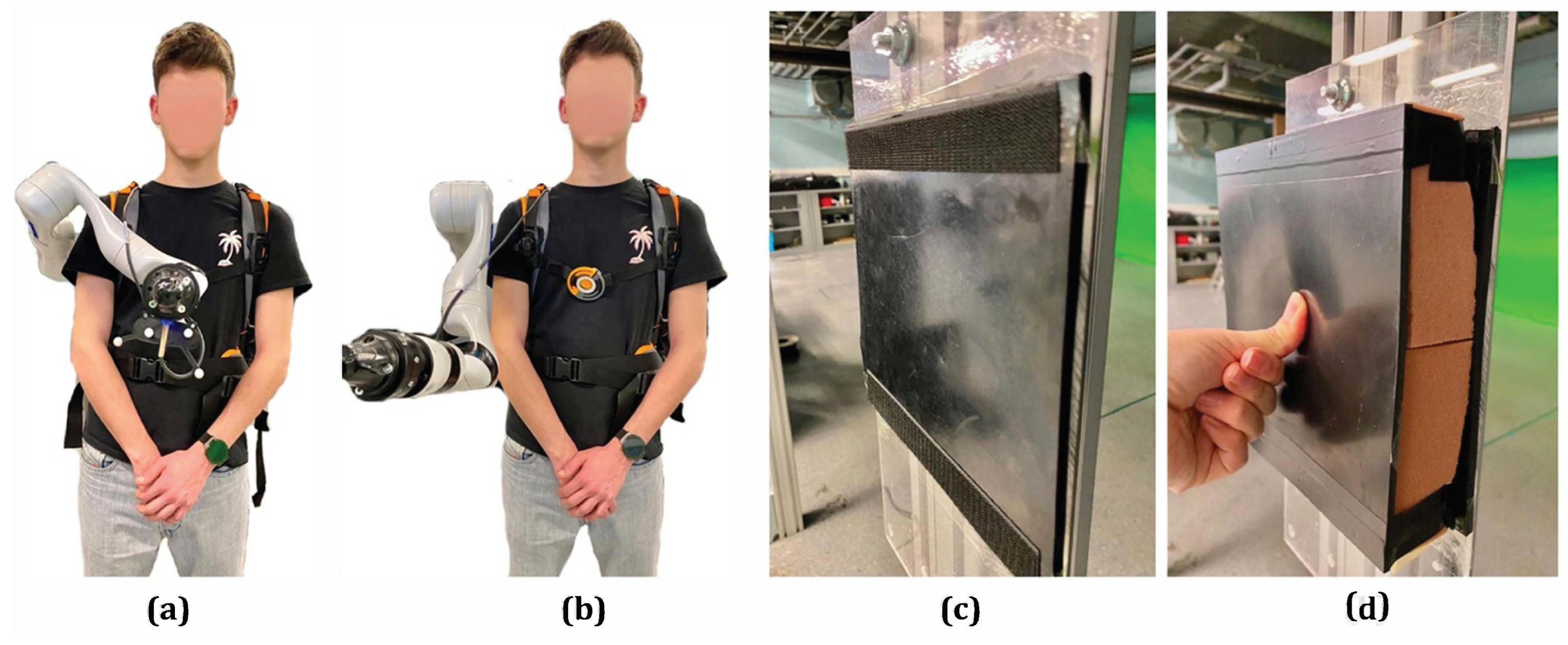
2.1. Experimental Setup

Based on the sample size of previous literature dealing with SRAs [11,24], thirteen participants (eleven males, two females) aged over 18 years (mean age 23.8 ± 1.4 years) participated in the experiment, after having provided written informed consent. The experiment was approved by the Sorbonne Université Research Ethics Committee (CER-SU) and conducted according to the Declaration of Helsinki.
During the experiment, the participant stands up in front of a vertical surface with a display (placed at the head level) while wearing the SRA, which remains still, in a predefined position (see Figure 1a). The participants can control the end-effector position using their body movements in order to apply a force with the SRA end-effector against the vertical surface (whose compliance can be changed from rigid to soft and vice versa). Participants were asked to exert specific amounts of force, as displayed by the graphical user interface (GUI).
The SRA was composed of the 7-DoF robotic arm Kinova Gen 3 Ultra lightweight attached to a modified Pellenc comfort harness [30] developed by the AGATHE team of ISIR-SU [31]. This robot’s form factor, light weight, and default hardware make it safe for cobotic applications in close interaction with the human body. The robot was turned on during the experiment, but it remained still in a given posture (achieved through joint position control), behaving like a rigid tool attached to the body. The SRA end-effector was equipped with a Robotiq FT 300-S 6-axis force sensor, characterized by a sampling rate of 100 Hz and a resolution of 0.0091 N, to measure the force applied by the end-effector to the environment.
The vibrotactile feedback system was composed of an electronic board and a vibrating system and was developed by improving a previous system [25,26,27]. The electronic board included 3 motor drivers (L2293Q by STMicroelectronics) to independently control up to 6 motors, a microcontroller unit (MCU) (STM32F446 by STMicroelectronics, Geneva, Switzerland), an FTDI module (FT232RL by FTDI Chip, Glasgow, U.K.), voltage regulators, a battery charger, and a module for Bluetooth. The electronic schematic and board were realized using the EAGLE 9.6.2 software (by Autodesk, Inc., San Francisco, CA, USA).
In the present work, only one motor was employed. The vibration motor (Model: 307-103 by Precision Microdrives Inc., London, UK) was placed in a 3D-printed case equipped with an elastic band (see Figure 1b). The case had a parallelepiped shape to maximize the contact surface with the body, a cylindrical hole that held the vibrator motor tightly, avoiding any vibration waste inside the case, and a small hole to tighten the cable. The vibrotactile stimulator was placed on the bicep of the preferred arm (see Figure 1c), according to [32], which demonstrated a high tactile acuity in this region.
On the display placed in front of the user, a GUI, shown in Figure 2a–c, provided the user with the task instructions (i.e., to exert with the SRA the amount of force highlighted on the monitor), together with a bar displaying the norm of the forces measured at the end-effector through the sensor. In particular, 3 different force levels were highlighted with an arrow-shaped text and a different color of the bar: low force (in green), medium force (in yellow), and high force (in red). Each level was a force interval that consisted of a fixed mean threshold (7 N, 14 N, and 21 N, represented by a thick dashed line) and a standard deviation of ±2 N (represented by two thin dashed lines). Additionally, we considered a rest level with a threshold of 0 N and a deviation of +2 N only in the positive range, to discard the non-contact case.

2.2. Vibrotactile Feedback and Data Processing

The interaction between the SRA end-effector and the vertical surface was measured by the FT sensor. The output was a 6 × 1 force and torque vector, which was serially received by a computer and processed by a Python script. Specifically, it computed the norm of the forces and the filter (Butterworth low-pass filter, 1st-order, 20 Hz), and both were shown on the display through the colored bar and drove the vibrotactile system through communication with the MCU.
Figure 2. Graphic interface during the familiarization (a), training (b), and testing (c) session. The level to reach is highlighted (training and testing sessions) with a darker color of the arrow. (d) The experimental protocol is divided into two blocks presented in a randomized order: with the inherent haptic feedback alone and with the addition of the vibrotactile haptic feedback. In both blocks, the subject faces a familiarization, a training, and a testing session.
Machines 11 01085 g002
Using the STM32CubeMX and an IDE based on Eclipse called SW4STM32, the MCU on the board was configured to receive the norm of the force value through serial communication. It then delivered to the motor drivers a pulse-width modulation (PWM) signal, whose duty cycle, proportional to the force value, accordingly modified the velocity of the rotating mass and, thus, the intensity of the vibration. In order to cover the entire span of the duty cycle the motors can operate with, the following linear mapping was used:
δ ( t ) = δ m i n + F ( δ m a x δ m i n ) ) F m a x
where δ is the duty cycle of the PWM, δ m i n = 0, δ m a x = 1, and they define the range of possible values of the duty cycle, while F is the force measured, with F m a x = 30 N the maximum value.

2.3. Experimental Protocol
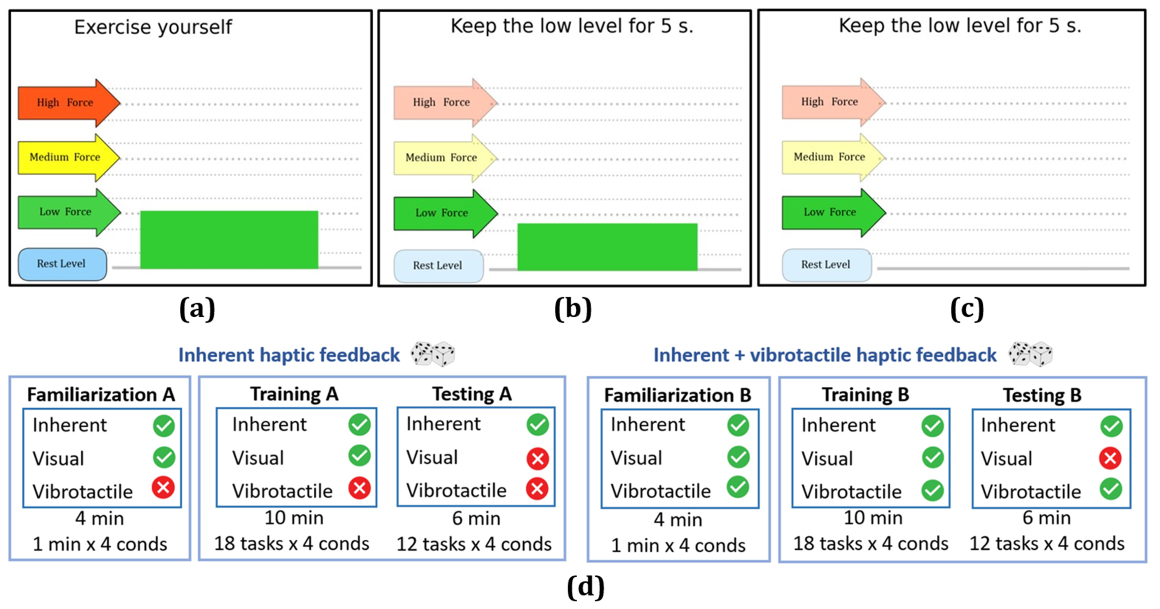
The task consisted of reaching, as fast as possible, the force level highlighted in the GUI (Figure 2a–c) by pushing with the robot end-effector against the vertical surface and maintaining the required force level until the end of the trial, which lasted 5 s. After that, participants had 3 s to return to the rest level, in order to start each trial from the same starting condition. Each level of force (three levels in total) was repeated the same number of times in a random order.
Additionally, to evaluate the participants’ ability to control the interaction force in different environmental situations, we used foam to change the stiffness of the vertical surface from rigid to compliant (Figure 3c,d), and we modified, through the KINOVA®KORTEX™ Web App, the robot posture from acentered(end-effector placed in front of the participant at the sternum level) to a lateral (Figure 3a,b) configuration.
Those postures were chosen because they would provide different inherent feedback. Additionally, they avoided any unforeseen contact between the SRA segments and the participant’s body during the experiment, taking into account different body sizes.
Hence, for each parameter (i.e.,SRA kinematic configuration and stiffness of the environment), we tested two different conditions (i.e., centered/lateral and rigid/compliant, respectively), resulting in four possible combinations that each participant faced in random order during each experimental session.
The experimental protocol was repeated twice, one for each feedback condition in random order: with vibrotactile and inherent feedback and with inherent feedback only.
As depicted in Figure 2d, each experimental block unfolded in the following way:
  • Familiarization session:
    Participants experienced 1 min in each of the 4 combinations while controlling the SRA with their body to exert a force against the vertical surface and observe on the graphical interface the amount of force exerted (Figure 2a).
  • Training session:
    Then, participants were asked to execute the task 18 times, 6 for each force level, for each of the 4 combinations of conditions. Thanks to the visual feedback provided through the GUI (Figure 2b), they were able to check the level of force exerted.
  • Testing session:
    Finally, participants performed the task 12 times, 4 for each force level, repeated for each of the 4 combinations, without any visual feedback of the level of force exerted (Figure 2c).
At the end of the two blocks (with and without the vibration feedback), the participant filled in a questionnaire based on a 5-point Likert scale (1 = a very little, 5 = a lot). The four most-relevant questions to evaluate the participants’ perception about the usefulness of the feedback were the following:
  • How much did you find the vibration helpful?
  • How much did you find the inherent sensation helpful?
  • How much was the vibrotactile feedback useful to adapt to the different conditions?
  • How much was the inherent sensation useful to adapt to the different conditions?

2.4. Data Analysis

The force data collected were analyzed with Python scripts, while the statistical analysis was performed on JASP (Version 0.13.1—Amsterdam—Netherlands). All the force data were preliminarily filtered using a 1st-order Butterworth low-pass filter with a cut frequency equal to 45 Hz.
Four metrics were extracted from the force data (always considering the norm of the force on the three axes) of the testing sessions:
  • The average error (e): the difference between the requested and the actual force, computed and averaged for each trial from the moment the participant reached for the first time the requested force interval to the end of the trial;
  • The normalized error ( | | e | | ): the average error divided by the requested force level;
  • The maintaining time (t): the sum of all the time intervals in which the participant maintained the exerted force within a band of ±2 N around the requested one;
  • The settling time ( t s ): the time from the instant in which the participant overcame 10% of the requested force level until the moment when he/she maintained the requested level for at least 0.15 s.
The normality of the data distribution was assessed using a Shapiro–Wilk test (p-value > 0.05). If the data distribution resulted in being not normal, the log10 transformation was applied. Statistical differences among conditions were tested using a three-way repeated-measures ANOVA with the feedback (vibrotactile + inherent and inherent), the environment stiffness (rigid and compliant), and the robot posture (centered and lateral) as factors.

3. Results

3.1. Overview of Force Profiles

Figure 4 shows the norm of the force collected during the training and testing sessions in both the inherent and inherent + vibrotactile conditions, for one repetition of a representative participant. In the training sessions, in which the visual feedback of the exerted force was provided (Figure 4a,b), the measured forces (blue) seemed to follow the requested levels (green) regardless of the conveyed haptic feedback. It was evident how, in the testing sessions, where the visual feedback was absent, the removal of the vibrotactile feedback (Figure 4d) led instead to an increase in the error, with the exerted force regularly reaching values over 50 N while the maximum requested level was 21 N ± 2 N (see Figure 4c,d).

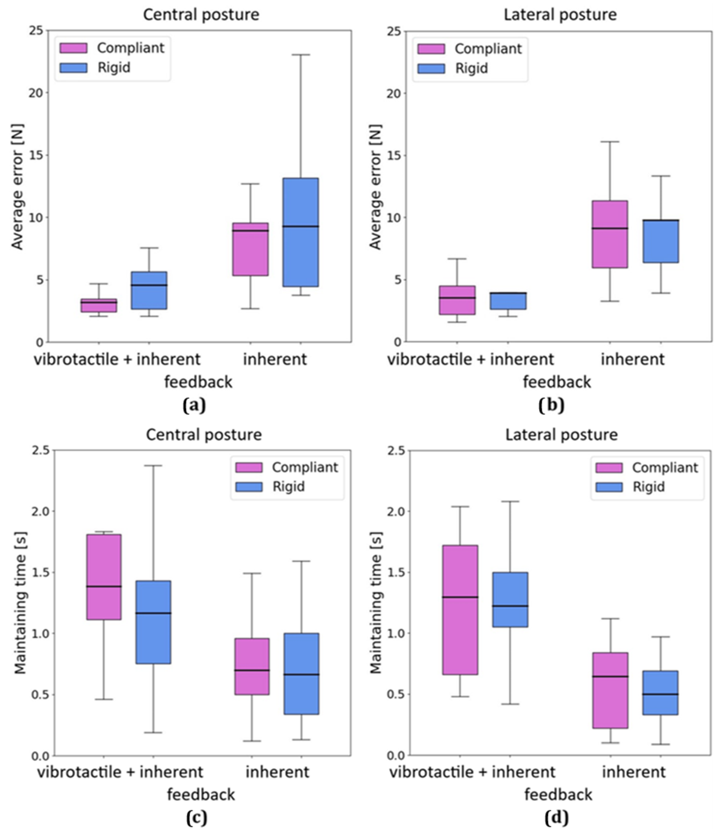
3.2. Effect of the Variation of Environmental Parameters

Considering the results averaged over the group of 13 participants, no significant effect of the surface stiffness (rigid and compliant), nor the robot kinematic posture (centered and lateral), nor the interaction between factors were observed on the overall performance. In Figure 5, we can observe that the performance with the compliant environment was slightly better (albeit not significantly) compared to the rigid one, in terms of lower average errors and higher maintaining times. A more-detailed explanation can be found in Section 4.

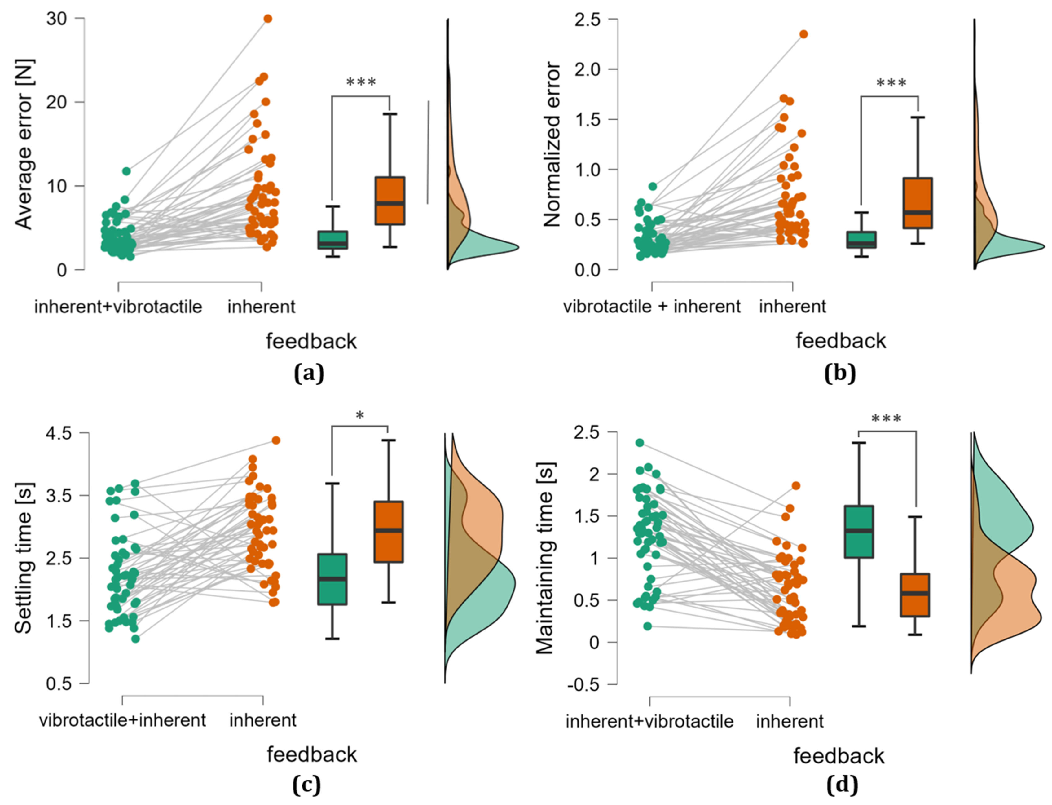
3.3. Effect of the Feedback

We found an effect of the feedback condition on the performance. Specifically, a statistically significant difference between feedback conditions (inherent and inherent + vibrotactile) was observed on all metrics, as shown in Figure 6. The presence of the vibrotactile feedback, indeed, improved performances in terms of:
  • Lower average errors ( F = 38 , p < 0.001 , e ¯ i n h e r e n t = 9.271 N, e ¯ i n h e r e n t + v i b . = 3.81 N);
  • Lower normalized errors ( F = 42 , p < 0.001 , | | e | | ¯ i n h e r e n t = 0.72 , | | e | | ¯ i n h e r e n t + v i b . = 0.311 );
  • Higher maintaining times ( F = 26 , p < 0.001 , t ¯ i n h e r e n t = 0.627 s, t ¯ i n h e r e n t + v i b . = 1.227 s);
  • Lower settling times ( F = 16 , p = 0.002 , t s ¯ i n h e r e n t = 2.96 s, t s ¯ i n h e r e n t + v i b . = 2.34 s).

3.4. Subjective Perception of Participants

The answers from the questionnaire are summarized in the pie charts presented in Figure 7. For the question,“How much was the vibration helpful?”, 100% answered either 4/5 or 5/5, while for the same question with “inherent sensation”, 77% answered with 3/5 or less. For the question, “How much was the vibrotactile feedback useful to adapt to the different conditions?”, 100% answered 4/5 or 5/5, while for the same question with “inherent sensation”, 85% answered 3/5 or less.

4. Discussion

In this study, we assessed the impact of a supplementary vibrotactile feedback on the control performance of 13 participants wearing an SRA during a force-regulation task, compared to the condition in which only the inherent feedback (due to the contact between the body and the robot) was present.
Examining the force profiles illustrated in Figure 4, it is evident that, during the training sessions, with the visual feedback, the user effectively reached and maintained the desired force levels regardless of the feedback condition. On the contrary, during the testing session without the visual feedback, participants performed worse when relying solely on the inherent feedback. In instances with inherent feedback alone, the participants struggled to consistently reach the requested force interval. However, the addition of the vibrotactile feedback mitigated this deficiency, enabling them to successfully attain and sustain the desired force levels.
From the statistical analysis, we obtained for all the analyzed metrics a significant improvement in the users’ performance due to the addition of the vibrotactile feedback. This result was supported by participants’ perception, given that 100% of the users found the vibration useful during the experiment.
As regards the effect of the environmental conditions and their interaction with the feedback, we did not find any statistically significant result, as shown in Figure 5. However, this could be due to the small dimension of the population, combined with the high number of conditions. Indeed, when receiving the vibrotactile feedback, participants not only performed better, but they seemed to improve their performance even more when dealing with a compliant environment (Figure 5). The questionnaire showed that 100% of the users felt a better ability to adapt to the different surface stiffness and robot postures with the addition of the vibrotactile feedback. One possible explanation is that relying solely on inherent feedback consistently yielded high error rates regardless of the object’s properties, such as the stiffness. This could have masked the difference between the different types of surfaces.
The presented outcomes aligned with the expectations, considering the existent literature, where various studies [13,14,16,17,18,19,23,25,26,27] have consistently demonstrated the benefits of incorporating additional force-driven vibrotactile feedback across diverse applications.
Although specific contexts, such as the one exemplified by Guggenheim et al. [11], may find inherent feedback satisfactory, our investigation showed that vibrotactile feedback allowed enhanced performance in tasks involving force regulation.
Yet, these results validated our hypothesis that the inherent feedback might not be robust enough to be used alone and that the vibrotactile feedback could provide information on the interaction in an intuitive way. We, thus, believe that the additional vibrotactile feedback could be the key point to lead the sensorimotor augmentation of the SRA to the next level, where humans can effortlessly control the SRA and perceive it as part of their own body.

5. Conclusions

The goal of our experiment was to assess the effect of a vibrotactile feedback carrying information on the force exerted through the SRA end-effector during a force regulation task performed by users who were wearing the SRA on their back. As expected, the additional vibrotactile feedback led to a statistically significant improvement in performance in terms of lower errors, higher maintaining time, and lower settling time, compared to a condition in which the users received only the inherent feedback provided by the contact between the user’s body and the wearable SRA.
It is noteworthy that the simplicity characterizing the implemented vibrotactile feedback system could potentially result in diminishing performance improvements when juxtaposed with more-advanced feedback modalities conveying richer information. This consideration gains significance when addressing complex scenarios where SRL control is not only contingent on bodily movements, but also factors in intricate environmental conditions.
While we reckon that the numerosity of the participants may have impacted the results concerning the effect on the environmental parameters (i.e., posture and stiffness), thus constituting a possible limitation of the study, the main effect of the general improvement in performance due to the addition of vibrotactile feedback compared to the inherent feedback alone was undoubtedly robust.
In future research, similar experiments could be conducted testing more variables and parameters: the ability of the users to adapt to the different environmental conditions using the vibrotactile feedback could be deepened, as well as the influence of the environmental stiffness and robot postures on the control of the application force. Also, the ability to perform a force regulation task actively controlling the SRA movements not only through body motion could be tested. Finally, the force information relayed by the vibrotactile feedback could be related to a more-realistic task, such as a virtual egg task (i.e., grasping a fragile object by exerting the minimum amount of force possible to grasp it, without damaging it).
We speculate that, thanks to the presented vibrotactile feedback, a patient suffering from upper limb paralysis could be able to exploit the SRA to open a door in front of him/her and regulate the force needed to open it without slamming it or to keep a glass of water without breaking it, nor dropping it. On the other side, a surgeon could use the SRA as a third arm controlled to manipulate surgical instruments; in this scenario, the need to discriminate the level of force applied is fundamental. In neither of these cases would inherent feedback be sufficient to regulate the right amount of force.

Author Contributions

Conceptualization, D.D., A.N., M.P., G.D.P., D.F. and N.J.; methodology, A.N., M.P., D.F. and N.J.; software, S.B.; formal analysis, S.B.; investigation, S.B.; validation, S.B. and D.D.; resources, D.D., A.N., M.P., D.F. and N.J.; data curation, S.B.; writing—original draft preparation, S.B.; writing—review and editing, S.B., D.D., A.N., M.P., G.D.P., D.F. and N.J.; visualization, S.B.; supervision, D.F. and N.J.; project administration, D.F. and N.J.; funding acquisition, G.D.P., D.F. and N.J. All authors have read and agreed to the published version of the manuscript.

Funding

This research was funded by the H2020 FET NIMA project (899626).

Institutional Review Board Statement

The study was conducted in accordance with the Declaration of Helsinki and approved by the Sorbonne Université research ethics committee (CER-SU).

Informed Consent Statement

Informed consent was obtained from all participants involved in the study.

Data Availability Statement

The data presented in this study are available upon request from the corresponding author. The data are not publicly available due to the privacy protection policy.

Conflicts of Interest

The authors declare no conflict of interest.

Abbreviations

The following abbreviations are used in this manuscript:
SRASupernumerary robotic arm
SRLSupernumerary robotic limb
SRLGSupernumerary robotic leg
SRFSupernumerary robotic finger
DoFDegree of freedom
MCUMicrocontroller unit
GUIGraphical user interface
PWMPulse-width modulation

References

  1. Yang, B.; Huang, J.; Chen, X.; Xiong, C.; Hasegawa, Y. Supernumerary robotic limbs: A review and future outlook. IEEE Trans. Med. Robot. Bionics 2021, 3, 623–639. [Google Scholar] [CrossRef]
  2. Davenport, C.; Parietti, F.; Asada, H.H. Design and biomechanical analysis of supernumerary robotic limbs. Dyn. Syst. Control Conf. 2012, 45295, 787–793. [Google Scholar]
  3. Llorens-Bonilla, B.; Parietti, F.; Asada, H.H. Demonstration-based control of supernumerary robotic limbs. In Proceedings of the 2012 IEEE/RSJ International Conference on Intelligent Robots and Systems, Vilamoura-Algarve, Portugal, 7–12 October 2012. [Google Scholar]
  4. Llorens Bonilla, B.; Asada, H.H. A robot on the shoulder: Coor dinated human-wearable robot control using colored petri nets and partial least squares predictions. In Proceedings of the 2014 IEEE International Conference on Robotics and Automation (ICRA), Hong Kong, China, 31 May–7 June 2014; pp. 119–125. [Google Scholar]
  5. Luo, J.; Gong, Z.; Su, Y.; Ruan, L.; Zhao, Y.; Asada, H.H.; Fu, C. Modeling and balance control of supernumerary robotic limb for overhead tasks. IEEE Robot. Autom. Lett. 2021, 6, 4125–4132. [Google Scholar] [CrossRef]
  6. Shin, C.; Bae, J.; Hong, D. Ceiling work scenario based hardware design and control algorithm of supernumerary robotic limbs. In Proceedings of the 2015 15th International Conference on Control, Automation and Systems (ICCAS), Busan, Republic of Korea, 13–16 October 2015; pp. 1228–1230. [Google Scholar]
  7. Parietti, F.; Chan, K.; Asada, H.H. Bracing the human body with supernumerary robotic limbs for physical assistance and load reduction. In Proceedings of the 2014 IEEE International Conference on Robotics and Automation (ICRA), Hong Kong, China, 31 May–7 June 2014; pp. 141–148. [Google Scholar]
  8. Parietti, F.; Asada, H.H. Supernumerary robotic limbs for aircraft fuselage assembly: Body stabilization and guidance by bracing. In Proceedings of the 2014 IEEE International Conference on Robotics and Automation (ICRA), Hong Kong, China, 31 May–7 June 2014; pp. 1176–1183. [Google Scholar]
  9. Parietti, F.; Chan, K.C.; Hunter, B.; Asada, H.H. Design and control of supernumerary robotic limbs for balance augmentation. In Proceedings of the 2015 IEEE International Conference on Robotics and Automation (ICRA), Seattle, WA, USA, 26–30 May 2015; pp. 5010–5017. [Google Scholar]
  10. Parietti, F.; Asada, H. Supernumerary robotic limbs for human body support. IEEE Trans. Robot. 2016, 32, 301–311. [Google Scholar] [CrossRef]
  11. Guggenheim, J.; Asada, H.H. Inherent haptic feedback from supernumerary robotic limbs. IEEE Trans. Haptics 2020, 14, 123–131. [Google Scholar] [CrossRef] [PubMed]
  12. Sobajima, M.; Sato, Y.; Xufeng, W.; Hasegawa, Y. Improvement of operability of extra robotic thumb using tactile feedback by electrical stimulation. In Proceedings of the 2015 International Symposium on Micro-NanoMechatronics and Human Science (MHS), Nagoya, Japan, 23–25 November 2015; pp. 1–3. [Google Scholar]
  13. Aoyama, T.; Shikida, H.; Schatz, R.; Hasegawa, Y. Operational learning with sensory feedback for controlling a robotic thumb using the posterior auricular muscle. Adv. Robot. 2019, 33, 243–253. [Google Scholar] [CrossRef]
  14. Shikida, H.; Noel, S.; Hasegawa, Y. Somatosensory Feedback Improves Operability of Extra Robotic Thumb Controlled by Vestigial Muscles. In Proceedings of the 2017 International Symposium on Micro-NanoMechatronics and Human Science (MHS), Nagoya, Japan, 3–6 December 2017; pp. 1–4. [Google Scholar]
  15. Hussain, I.; Meli, L.; Pacchierotti, C.; Salvietti, G.; Prattichizzo, D. Vibrotactile haptic feedback for intuitive control of robotic extra fingers. In Proceedings of the 2015 IEEE World Haptics Conference (WHC), Evanston, IL, USA, 22–26 June 2015; pp. 394–399. [Google Scholar]
  16. Hussain, I.; Salvietti, G.; Meli, L.; Pacchierotti, C. Using the Robotic Sixth Finger and Vibrotactile Feedbackfor Grasp Compensation in Chronic Stroke Patients. In Proceedings of the 2015 IEEE International Conference on Rehabilitation Robotics (ICORR), Singapore, 11–14 August 2015. [Google Scholar]
  17. Christiansen, R.; Contreras-Vidal, J.L.; Gillespie, R.B.; Shewokis, P.A.; O’Malley, M.K. Vibrotactile feedback of pose error enhances myoelectric control of a prosthetic hand. In Proceedings of the 2013 World Haptics Conference (WHC), Daejeon, Republic of Korea, 14–17 April 2013; pp. 531–536. [Google Scholar]
  18. Fröhner, J.; Salvietti, G.; Beckerle, P.; Prattichizzo, D. Can wearable haptic devices foster the embodiment of virtual limbs? IEEE Trans. Haptics 2018, 12, 339–349. [Google Scholar] [CrossRef] [PubMed]
  19. Witteveen, H.J.; Droog, E.A.; Rietman, J.S.; Veltink, P.H. Vibro-and electrotactile user feedback on hand opening for myoelectric forearm prostheses. IEEE Trans. Biomed. Eng. 2012, 59, 2219–2226. [Google Scholar] [CrossRef] [PubMed]
  20. Wheeler, J.; Bark, K.; Savall, J.; Cutkosky, M. Investigation of rotational skin stretch for proprioceptive feedback with application to myoelectric systems. IEEE Trans. Neural Syst. Rehabil. Eng. 2010, 18, 58–66. [Google Scholar] [CrossRef] [PubMed]
  21. Clemente, F.; Valle, G.; Controzzi, M.; Strauss, I.; Iberite, F.; Stieglitz, T.; Cipriani, C. Intraneural sensory feedback restores grip force control and motor coordination while using a prosthetic hand. J. Neural Eng. 2019, 16, 026034. [Google Scholar] [CrossRef] [PubMed]
  22. Zollo, L.; Di Pino, G.; Ciancio, A.L.; Ranieri, F.; Cordella, F.; Gentile, C.; Guglielmelli, E. Restoring tactile sensations via neural interfaces for real-time force-and-slippage closed-loop control of bionic hands. Sci. Rob. 2019, 4, 27. [Google Scholar] [CrossRef] [PubMed]
  23. Markovic, M.; Schweisfurth, M.A.; Engels, L.F.; Bentz, T.; Wüstefeld, D.; Farina, D.; Dosen, S. The clinical relevance of advanced artificial feedback in the control of a multi-functional myoelectric prosthesis. J. Neuroeng. Rehabil. 2018, 15, 1–15. [Google Scholar] [CrossRef] [PubMed]
  24. Saraiji, M.; Sasaki, T.; Kunze, K.; Minamizawa, K.; Inami, M. Metaarms: Body remapping using feet-controlled artificial arms. In Proceedings of the UIST’18: The 31st Annual ACM Symposium on User Interface Software and Technology, Berlin, Germany, 14 October 2018; pp. 65–74. [Google Scholar]
  25. Pinardi, M.; Raiano, L.; Noccaro, A.; Formica, D.; Di Pino, G. Cartesian Space Feedback for Real Time Tracking of a Supernumerary Robotic Limb: A Pilot Study. In Proceedings of the 2021 10th International IEEE/EMBS Conference on Neural Engineering (NER), Virtual Event, 4–6 May 2021; pp. 889–892. [Google Scholar]
  26. Pinardi, M.; Noccaro, A.; Raiano, L.; Formica, D.; Di Pino, G. Comparing end-effector position and joint angle feedback for online robotic limb tracking. PLoS ONE 2023, 18, e0286566. [Google Scholar] [CrossRef] [PubMed]
  27. Noccaro, A.; Raiano, L.; Pinardi, M.; Formica, D.; Di Pino, G. A novel proprioceptive feedback system for supernumerary robotic limb. In Proceedings of the 2020 8th IEEE RAS/EMBS International Conference for Biomedical Robotics and Biomechatronics (BioRob), New York, NY, USA, 29 November–1 December 2020; pp. 1024–1029. [Google Scholar]
  28. Sanchez, J.H.; Amanhoud, W.; Haget, A.; Bleuler, H.; Billard, A.; Bouri, M. Four-arm manipulation via feet interfaces. arXiv 2019, arXiv:1909.04993. [Google Scholar]
  29. Pinardi, M.; Longo, M.R.; Formica, D.; Strbac, M.; Mehring, C.; Burdet, E.; Di Pino, G. Impact of supplementary sensory feedback on the control and embodiment in human movement augmentation. Commun. Eng. 2023, 2, 64. [Google Scholar] [CrossRef]
  30. Available online: https://store.pellenc.com/batteries/357-harnais-confort.html (accessed on 12 December 2023).
  31. Khoramshahi, M.; Poignant, A.; Morel, G.; Jarrassé, N. A Practical Control Approach for Safe Collaborative Supernumerary Robotic Arms. In Proceedings of the 2023 IEEE International Conference on Advanced Robotics and Its Social Impacts (ARSO), Berlin, Germany, 5–7 June 2023. [Google Scholar]
  32. Al-Sada, M.; Jiang, K.; Ranade, S.; Piao, X.; Höglund, T.; Nakajima, T. HapticSerpent: A wearable haptic feedback robot for VR. In Proceedings of the CHI’18: CHI Conference on Human Factors in Computing Systems, Montreal, QC, Canada, 21–26 April 2018; pp. 1–6. [Google Scholar]
Figure 1. (a) Scheme of the experimental setup; (b) the vibrotactile feedback system; (c) how the vibrotactile system is mounted on the participant’s arm: the case and the elastic band.
Machines 11 01085 g001
Figure 3. (a) The centered and (b) the lateral kinematic configurations of the SRA from a front view. The vertical surface (c) without the foam (rigid) and (d) with the foam (compliant).
Machines 11 01085 g003
Figure 4. Example of the force profiles of one participant during a training session (a,b) and a testing session (c,d) obtained in the two feedback conditions (inherent and inherent + vibrotactile), with the same combination of conditions (compliant vertical surface and centered kinematic posture). On the right is highlighted with the green tick the feedback available, while with the red cross, the feedback is unavailable. The threshold of the requested level of force is represented by the green line and the measured (and filtered) level of force, respectively, by the blue lines, for the training sessions, while the pink ones are for the testing sessions.
Machines 11 01085 g004
Figure 5. Performance comparison between the two feedback conditions and for different environmental conditions (i.e., stiffness level and SRA posture) in terms of (a,b) average error and (c,d) maintaining time. The mean and the standard deviation of the metric over all the trials and participants with the same conditions are shown.
Machines 11 01085 g005
Figure 6. Performance comparison between the two feedback conditions in terms of (a) average error, (b) normalized error, (c) maintaining time, and (d) settling time. Each dot represents the mean of the metric over the trials with the same combination of conditions of one participant. These results are relative to all the participants, including both the stiffness and posture conditions. The asterisks (*) represent the p-value of the statistical test: * p ≤ 0.1, *** p ≤ 0.001.
Machines 11 01085 g006
Figure 7. The pie charts realized using Microsoft Excel relative to the questionnaire answers of all 13 participants. The colours from red to dark green represent the answers based on a 5-point Likert scale (1 = a very little, 5 = a lot) given by each participant to the four questions: (a) How much was the vibrotactile feedback useful to adapt to the different conditions?, (b) How much was the inherent sensation useful to adapt to the different conditions?, (c) How much did you find the vibration helpful?, (d) How much did you find the inherent sensation helpful?
Machines 11 01085 g007
Disclaimer/Publisher’s Note: The statements, opinions and data contained in all publications are solely those of the individual author(s) and contributor(s) and not of MDPI and/or the editor(s). MDPI and/or the editor(s) disclaim responsibility for any injury to people or property resulting from any ideas, methods, instructions or products referred to in the content.

