Article

Assessment of Residual Useful Life of Sun Gear in a Planetary Gearbox Based on Dynamic Wear Behaviors Analyses

1
School of Advanced Manufacturing, Fuzhou University, Jinjiang 362200, China
2
School of Mechanical Engineering and Automation, Fuzhou University, Fuzhou 350116, China
*
Author to whom correspondence should be addressed.
Machines 2023, 11(2), 149; https://doi.org/10.3390/machines11020149
Submission received: 14 December 2022 / Revised: 14 January 2023 / Accepted: 17 January 2023 / Published: 21 January 2023
(This article belongs to the Section Friction and Tribology)

Abstract

:
For proactively arranged downtime and maintenance of the gearbox, the accurate assessment of residual useful life (RUL) for worn-surface gear is a critical problem that needs to be solved. In light of this, a novel dynamic assessment methodology for RUL of sun gear was proposed by coupling Archard’s wear model and a nonlinear dynamics model. By modifying the internal excitation model, the effect of tooth surface wear is included in the dynamics model. Then, the effect of dynamic behavior on the wear process of the tooth surface is further fed back by the dynamic meshing force. On this basis, the influence of input speed, torque load and initial wear depth on the RUL was analyzed using a planetary gear NGW11-6 as an example. The results indicate that the torque load has the greatest influence on the RUL, followed by the initial wear depth, and that the input speed has the least influence. The established methodology will provide a theoretical basis for the RUL assessment and scheduled maintenance of transmission systems with worn-surface gears.

1. Introduction

The planetary gearbox has found wide application in many diverse power transmission systems owing to its advantages of high power density, compact structural volume and steady transmission ratio [1,2]. Tooth surface wear always accompanies the gear transmission system from the beginning of use to the failure of scrap. As a material removal process, surface wear will gradually change the micro-geometry morphology and load distribution of the contacting tooth flanks, which not only reduces the accuracy and efficiency of the gear system, but also worsens the vibration behavior and ultimately leads to tooth breakage [3]. In view of this, interest in gear wear mechanisms has increased since the 1990s. To improve the service performance and safety of planetary gearboxes, it is necessary to prioritize the RUL of gears with worn surface. Although numerous investigations have been conducted to diagnose tooth surface wear, assessing the RUL for worn-surface gears still remains a challenge for the academic and industrial communities. According to the focal points of the investigation, previous research on tooth surface wear has been roughly divided into three groups: (1) Focusing on the influence of each parameter on the surface wear distribution; (2) Discussing the effect of surface wear on vibration characteristics of gearbox; (3) Extracting surface wear fault characteristics from vibration signals of gearbox.
For the first group, it is common to establish the prediction model of tooth surface wear, including the static prediction models [4,5,6] and the dynamic prediction models [7,8,9]. Based on the modeling, the influences of material, speed, lubrication, load, modification and other parameters on the tooth surface wear distribution were further investigated. Li and Olofsson [10] studied the wear characteristics of two different powder metallurgy materials and showed that the wear coefficient decreased with increasing pore size in the gear material. Huangfu et al. [11] discussed the influence of rotational speed on wear depth in combination with the loaded tooth contact analysis method with a gearbox dynamics model. According to the wear prediction model in mixed lubrication conditions, Akbarzadeh and Khonsari [12] and Zhang et al. [13] examined the gear performance in terms of pressure, speed, friction coefficient, and especially, wear rate, by applying thermo-elasto-hydrodynamic lubrication with rough surface contact. Based on the FZG gear wear test, Brandão et al. [14] analyzed the influences of base stock, contact load, and specific film thickness on the surface wear. The findings reveal that contact load has an effect on wear coefficient, and that the base stock has a significant effect. In addition, Kahraman et al. [15] used a wear prediction model to investigate the effect of profile deviations on the distribution of helical gear wear due to tooth modification or manufacturing error.
For the second group, the common point is to model the transmission dynamics with worn-surface gear, and the fundamental problem is to explore the effect of worn surface on the internal excitations. Following this track, the effects of surface wear on the main internal excitations of the meshing pair were studied in detail [16]. For instance, Shen et al. [17] proposed an improved time-varying meshing stiffness (TVMS) model to take into account the wear effect and to assess the effect of surface wear on stiffness excitation. The analysis results by Chen et al. show that tooth surface wear has significant influence on the extremum and distribution of TVMS and static transmission error (STE) [18]. Considering that the backlash of the gear transmission system changes over time under the action of the load torque, Wu et al. [19] used an iterative method to analyze backlash excitation generated by wear accumulation of the gear pair in the planetary transmission system. As material removal progresses, tooth surface wear will gradually change the micro-geometry morphology and load distribution of the contacting tooth flanks, which has a major impact on the accuracy, efficiency and dynamics of the transmission system. Therefore, another research focus is to further discuss the effect of the wear process of a tooth surface on the vibration characteristics of the transmission system. For example, Atanasiu et al. [20] and Yuksel et al. [21] studied the influence of surface wear on the relative vibration displacement and the contact force based on the dynamics model of single-pair helical gear and planetary gear train, respectively. Based on the modeling of dynamics, Yang et al. [22] and Geng et al. [23] explored the influence of surface wear on the periodic motion of gear trains from the Poincare cross section graph, bifurcation diagram, and so on.
For the third group, the common point is how to extract and diagnose wear fault from various signals of gearboxes. To this point, as far as the author knows, there have been numerous in-depth studies in the literature. For instance, Chang et al. [24] proposed a new method to obtain comprehensive and high-resolution wear information through non-contact imaging measurement, and monitored the evolution of tooth surface wear. Considering that tooth surface wear can cause the driving motor current signal modulation phenomenon, Zhang et al. [25] presented a tooth surface wear-monitoring method based on a bispectrum analysis of the motor current modulation signal. Since the abrasive particles in the lubricating oil contain a lot of effective information, the wear state of the gearbox can be assessed by online monitoring of the relevant parameters of the abrasive particles in the lubricating oil [26]. Comparatively, fault diagnosis and monitoring using vibration signals is more widely used in gear transmission systems. For instance, Feng et al. [27] and Feng et al. [28] tracked the wear evolutionary process by using the cyclic smoothness index and cyclic-correntropy of vibration signals. Laval et al. [29] used Hilbert demodulation technology to quantify the actual vibration data from a worn gearbox. Hu et al. [30] proposed a time-synchronous averaging method to extract the indicators describing the wear state of the tooth surface from vibration signals.
In summary, scientists have done a great deal of research on wear modeling, analyzing and diagnosing, which provides a solid foundation for the safety and steady work of gear transmission systems. However, research on how to predict the RUL of worn-surface gear with known wear depth is relatively scarce [31]. It is known that the useful life of a gear is considerably lower than the estimated life in the design stage owing to the existence of surface wear. This is because the coupling effect of time-varying working conditions and dynamic wear process is not taken into account when predicting the RUL for worn-surface gear. Aiming at this research gap, a RUL prediction methodology is established from the perspective of the coupling of wear mechanism and the dynamics model. Therefore, the contributions and innovations of this paper are as follows: (1) The models of time-varying meshing stiffness and static transmission error of gear with surface wear were modified and analyzed; (2) An assessment model of residual useful life of worn-surface sun gear under variable working conditions was established; (3) The effects of initial depth of surface wear on dynamic meshing force and residual useful life are revealed. The following contents are organized: a lumped parameter dynamics model and an internal excitation model are modified to explore the effect of tooth surface wear in Section 2. Then, a RUL prediction methodology for worn-surface gear is proposed in Section 3, based on the coupling of wear model and dynamics model. In Section 4, the effects of input speed, load and initial wear on the RUL of a planetary gearbox are demonstrated. Finally, some conclusions on the full contribution are made.

2. Dynamic Modeling for a Planetary Gear Train with Worn-Surface Gear

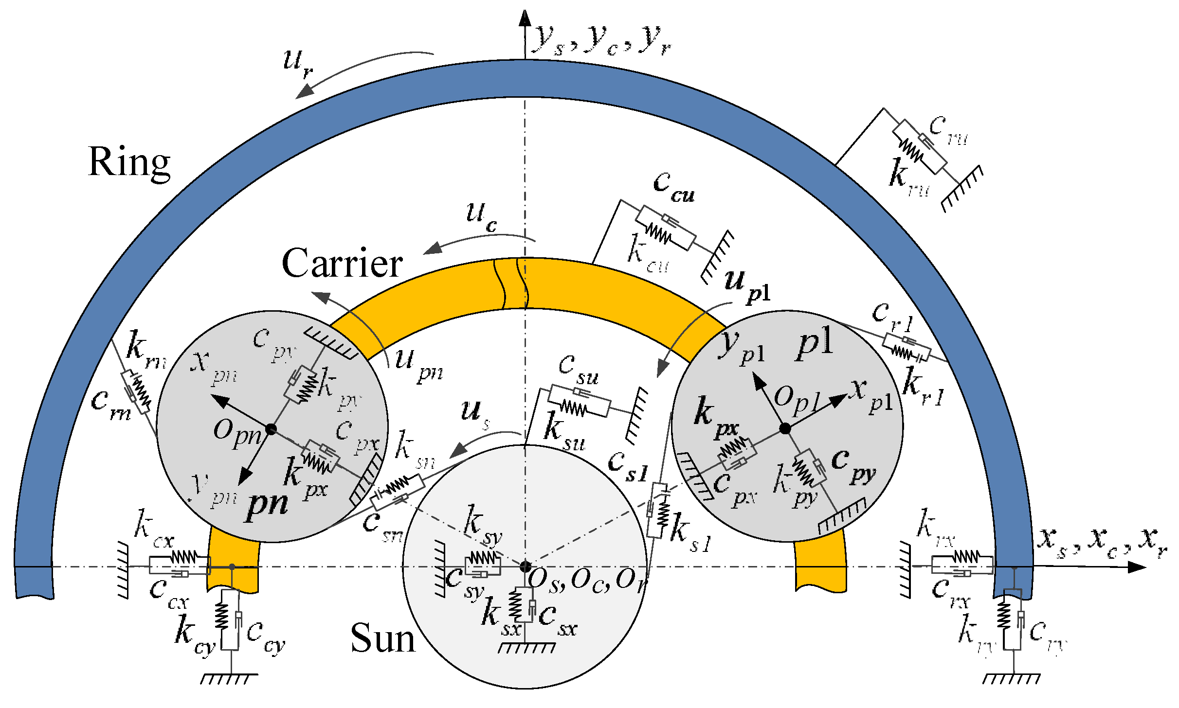
2.1. Description of the Nonlinear Dynamic Model

In this section, a lumped parameter translational-rotational-coupled model of a planetary gear system with tooth-worn surface is proposed by considering the wear effect on TVMS and STE. The presented lumped parameter nonlinear dynamic model is illustrated as shown in Figure 1.
Herein, ohxhyh (h = s, r, c, pn) is a body-fixed coordinate system with origin locating at the center of the corresponding component. The subscripts ‘s’, ‘r’, ‘c’ and ‘pn’ represent the sun gear, ring gear, planet carrier and nth planet gear, respectively. For derivation convenience, assume each planet has identical mass, inertia, meshing stiffness and meshing damping. khj and chj (j = x, y, u) denote the support stiffness and support damping of component h in x, y and u directions. ksn, krn and csn, crn represent the meshing stiffness and meshing damping along the line of action of external meshing pair (s-pn) and internal meshing pair (r-pn), respectively.
According to the above definitions, the generalized coordinate vector q can be expressed as:
q = x s , y s , u s , x c , y c , u c , x r , y r , u r , x p n , y p n , u p n T ( n = 1 , 2 , )
where xh and yh are the translational displacements of component h along the direction of x and y, respectively. uh is the torsional displacements along the direction of rotation.
Define f (δln) (l = s, r) as a nonlinear function to describe the influence of backlash; it can be written as
f δ l n = δ l n b l n 0 δ l n + b l n δ l n > b l n b l n δ l n b l n δ l n < b l n , l = s or r
where 2bln is the backlash value of the s-pn and r-pn meshing pair. δln denotes the relative displacement of the meshing pairs along the line of action. There are also the following:
δ s n = x s x p n sin ψ s n + y s y p n cos ψ s n + u s + u p n e s n h s n
δ r n = x r x p n sin ψ r n + y r y p n cos ψ r n + u r u p n e r n h r n
where esn and ern denote the STE of s-pn and r-pn meshing pair; hsn and hsn denote the wear depth along the line of action; ψsn and ψrn denote the relative meshing angle of the sun gear and ring gear with the nth planet gear; it can be expressed as
ψ s n = ψ p n α s
ψ r n = ψ p n + α r
where αs and αr denote the meshing angle of s-pn and r-pn meshing pair; ψpn denotes the position angle of nth planet.

2.2. The Differential Equation of Motion for Planetary Gear Train

The dynamical equations for the planetary gear train can be synthesized from the differential equations of motion of each subsystem, including the sun gear subsystem, the planet carrier subsystem, the ring gear subsystem and the planet gear subsystems. The differential equations of motion for each subsystem are as follows:
(1)
The differential equations of motion for the sun gear subsystem
m s x ¨ s 2 ω c y ˙ s ω c 2 x s + k s x x s + c s x x ˙ s n = 1 N k s n f δ s n + c s n δ ˙ s n sin ψ s n = 0 m s y ¨ s + 2 ω c x ˙ s ω c 2 y s + k s y y s + c s y y ˙ s + n = 1 N k s n f δ s n + c s n δ ˙ s n cos ψ s n = 0 I s r bs 2 u ¨ s + k s u u s + c s u u ˙ s + n = 1 N k s n f δ s n + c s n δ ˙ s n = T s r bs
where ms and Is represent the mass and rotational inertia of the sun gear, respectively. r bs represents the base circle radius of the sun gear. T s represents the input torque on the sun gear. ωc represents the rotation speed of the planet carrier.
(2)
The differential equations of motion for the planet carrier subsystem
m c x ¨ c 2 ω c y ˙ c ω c 2 x c + k c x x c + c c x x ˙ c + n = 1 N k p n x · δ c n x + c p n x δ ˙ c n x = 0 m c y ¨ c + 2 ω c x ˙ c ω c 2 y c + k c y y c + c c y y ˙ c + n = 1 N k p n y · δ c n y + c p n y δ ˙ c n y = 0 I c r c 2 u ¨ c + k c u u c + c c u u ˙ c + n = 1 N k p n u · δ c n u + c p n u δ ˙ c n u = T c r c
where mc and Ic represent the mass and rotational inertia of the planet carrier, respectively. r c represents the radius of the pin circle at the planet carrier. T c represents the load torque on the planet carrier. δcnx, δcny and δcnu denote the relative displacement between the nth planet gear and the planet carrier along the direction of x, y and u, respectively. These can be calculated as
δ c n x = x c x p n u c sin ψ p n
δ c n y = y c y p n + u c cos ψ p n
δ c n u = x p n x c sin ψ p n y p n y c cos ψ p n + u c
(3)
The differential equations of motion for the ring gear subsystem
m r x ¨ r 2 ω c y ˙ r ω c 2 x r + k r x x r + c r x x ˙ r n = 1 N k r n f δ r n + c r n δ ˙ r n sin ψ r n = 0 m r y ¨ r + 2 ω c x ˙ r ω c 2 y r + k r y y r + c r y y ˙ r + n = 1 N k r n f δ r n + c r n δ ˙ r n cos ψ r n = 0 I r r br 2 u ¨ r + k r u u r + c r u u ˙ r + n = 1 N k r n f δ r n + c r n δ ˙ r n = 0
where mr and Ir represent the mass and rotational inertia of the ring gear, respectively. rbr represents the base circle radius of the ring gear.
(4)
The differential equations of motion for the nth planet gear subsystem
m p x ¨ p n 2 ω c y ˙ p n ω c 2 x p n + k s n f δ s n + c s n δ ˙ s n sin ψ s n + k r n f δ r n + c r n δ ˙ r n sin ψ r n c p n x δ ˙ c n x k p n x δ c n x = 0 m p y ¨ p n + 2 ω c x ˙ p n ω c 2 y p n k s n f δ s n + c s n δ ˙ s n cos ψ s n k r n f δ r n + c r n δ ˙ r n cos ψ r n c p n y δ ˙ c n y k p n y δ c n y = 0 I p r bp 2 u ¨ p n + k s n f δ s n + c s n δ ˙ s n k r n f δ r n + c r n δ ˙ r n = 0
where mp and Ip represent the mass and rotational inertia of the planet gear, respectively. rbp represents the base circle radius of the planet gear.
By the 2nd Newtonian law, the dynamic model of planetary gear transmission system can be obtained by coupling the differential equations of motion of the above subsystem, as shown:
M q ¨ + C b + C m + ω c G q ˙ + K b + K m ω c 2 K ω q = F
where M represents the mass matrix. C b and K b represent the support damping and support stiffness matrix, respectively. C m and K m represent the meshing damping and meshing stiffness matrix, respectively. G represents the gyroscopic matrix. K ω represents the centripetal stiffness matrix. F represents the combination of external and internal excitation forces. Reference [32] can be used to obtain the correlation matrix. Herein, the fourth-order variable-step Runge–Kutta method is used to solve the differential equations of motion.

2.3. Internal Excitation with Tooth Surface Wear

(1) Model of TVMS
TVMS is a critical internal excitation in a gear transmission system [33], which is usually calculated by the energy method. The application of the energy method in the calculation of TVMS for a worn-surface meshing pair is briefly discussed below.
A tooth model with surface wear is established firstly as shown in Figure 2. Herein, it is assumed that the surface wear is equal in the direction of tooth width. The healthy profile is represented by a solid line, and the worn-surface profile is represented by a dashed line. O1O2 is the centerline of the gear tooth. hw denotes the depth of surface wear. Then, the force diagram of tooth with surface wear is analyzed as in Figure 3. Herein, O denotes the geometric center of the gear. Segments BC and CD are the involute curve and transition curve of the tooth profile, respectively. Fm denotes the meshing force along the line of action. Fa and Fb are the components of Fm along the radial direction and the tangential direction. Point P designates the meshing point, and P1 and P2 designate a random position on the transition curve and involute curve of the tooth profile. α and α2 denote the angles between the involute generating line corresponding to points P and P2 and the y-axis. xα, x1, x2 and yα, y1, y2 are the distance from points P, P1 and P2 to the y-axis and x-axis, respectively. Rb and Rf denote the radii of base circle and root circle of gear. αb and αf are the angles between OC, OD and x-axis.
The analysis found that tooth surface wear affects the tooth cross-sectional area and the rotational inertia. The wear effect is expressed as follows:
A 2 wear = 2 y 2 h w x 2 B
I 2 wear = 1 12 2 y 2 h w x 2 3 B + A 2 wear R b sin α b 2 y 2 h w x 2 2 2
where A 2 wear and I 2 wear denote the cross-sectional area and the rotational inertia of the worn-surface tooth. B denotes the tooth width.
Furthermore, bending stiffness k b wear , shear stiffness k s wear and axial compression stiffness k a wear affected by tooth surface wear need to be rewritten as
1 k b wear = x D x C cos α x α x 1 y α h w ( x 2 ) sin α 2 E 2 y 1 3 B / 3 d x 1 + x C x α cos α x α x 2 y α h w ( x 2 ) sin α 2 E I 2 wear d x 2
1 k s wear = x D x C 1.2 1 + ν cos 2 α E y 1 B d x 1 + x C x α 2.4 1 + ν cos 2 α E A 2 wear d x 2
1 k a wear = x D x C sin 2 α 2 E y 1 B d x 1 + x C x α sin 2 α E A 2 wear d x 2
where E denotes the Young’s modulus, and ν denotes the Poisson’s ratio.
The Hertz contact stiffness k h and fillet-foundation stiffness k f are unaffected by tooth surface wear, which can be calculated as [34]:
1 k h = 4 1 ν 2 π E B
1 k f = cos 2 α E B L f μ f 2 S f 2 + M f μ f S f + P f 1 + Q f tan 2 α
Herein,
μ f = R b cos α R f ,   S f = 2 R f α f
α f = 1 Z π 2 + 2 tan α 0 ( h a * R ρ ) + 2 R ρ / m n cos α 0
where h a * denotes the addendum coefficient. mn denotes the gear module. Rρ denotes the radius of curvature of the root transition curve. α0 is the pressure angle. The coefficients Lf, Mf, Pf and Qf can be expressed by the polynomial
X fi h fi , α f = A fi α f 2 + B fi h fi 2 + C fi h fi α f + D fi α f + E fi h fi + F fi , h fi = R f R int
where the coefficient values of Afi, Bfi, Cfi, Dfi, Efi and Ffi can be referred to reference [35]. Rint denotes the radius of the inner hole of the gear.
Then, the TVMS with tooth surface wear is calculated by
k wear = i = 1 I 1 1 k h , i + 1 k a 1 , i wear + 1 k b 1 , i wear + 1 k s 1 , i wear + 1 λ 1 k f 1 , i + 1 k a 2 , i wear + 1 k b 2 , i wear + 1 k s 2 , i wear + 1 λ 2 k f 2 , i
where I represents the meshing pairs. k a 1 , i wear , k b 1 , i wear , k s 1 , i wear and k a 2 , i wear , k b 2 , i wear , k s 2 , i wear represent the axial compressive stiffness, bending stiffness and shear stiffness of driving and driven gears with tooth surface wear. k f 1 , i and k f 2 , i represent the fillet-foundation stiffness of corresponding gear. λ1 and λ2 represent the correction coefficients. The subscript i denotes the ith meshing pair.
In order to introduce the periodic mesh stiffness kwear into the dynamic model, it needs to be further expressed as a time-varying variable. The Fourier series function is the most common form and its expression can be written as the following [36]:
k s n t k snm + v = 1 l k s a n v cos v ω m t + k s b n v sin v ω m t
k r n t k rnm + v = 1 l k r a n v cos v ω m t + k r b n v sin v ω m t
where ksnm and krnm are the mean values of mesh stiffness of sun–planet and planet–ring gear meshing pairs. k s a n v , k s b n v and k r a n v , k r b n v are the amplitudes of the vth order harmonic stiffness of corresponding meshing pair. ωm is the mesh frequency.
(2) Model of STE
Static transmission error inevitably exists in gear transmission system due to errors and deformations. The comprehensive error can be modeled as
T E = E M + E A + E L
where EM and EA denote the manufacturing error and installation error. EL denotes the elastic deformation under load.
Considering the uncertainty of manufacturing errors in practical engineering, it is more appropriate to construct a gear manufacturing error model by the probability distribution statistics method. Therefore, the manufacturing error of the gear can be calculated as [37]:
E M = 1 2 Δ F t Δ f t sin θ + 1 2 Δ f t sin z θ
where Δ F t and Δ f t represent the gear total tangential composite deviation and single tooth tangential composite deviation. z denotes the number of teeth. θ is rolling angle uniformly and randomly distributed in the range of [0, 2π].
The installation error is generally reflected in the fit of the shaft and bore between gear and shaft, shaft and bearing, and bearing and gearbox. Therefore, the installation error can generally be described by the tolerance and calculated as
E A = q = 1 3 Δ e q sin θ q
where Δ e 1 , Δ e 2 and Δ e 3 represent the fit tolerance between gear and shaft, shaft and bearing cone, and bearing cup and gearbox. θq is the rotation angle, satisfying uniformly and randomly distribution in the range of [0, 2π].
Elastic deformation is non-negligible as the tooth surface is affected by the meshing force. It can be calculated by Hooke’s law as
E L = F t k 1 t
where F(t) represents the component of meshing force undertaken by a gear tooth. k1(t) represents the bearing stiffness of the tooth.
Then, the STE of the meshing pair can be calculated as
e S T E = T E p + T E g = E Mp + E Ap + E Lp + E Mg + E Ag + E Lg
where eSTE represents the STE. TEp and TEg represent the comprehensive error of the driving gear and driven gear, respectively. E Mp , E Ap , E Lp and E Mg , E Ag , E Lg represent manufacturing error, installation error and elastic deformation of driving gear and driven gear, respectively.
The effect of tooth surface wear on the direction of the line of action is represented by displacement excitation, which can be calculated as
h w wear = h w x 2 cos ( α 2 )
Considering that a meshing pair consists of a driving and a driven gear, the effect of surface wear on the composite error of a meshing pair can be expressed as
h pg wear = h w 1 wear + h w 2 wear
where h w 1 wear and h w 2 wear denote the depth of surface wear of driving and driven gear, respectively.
Then, the STE in a single meshing pair with worn surface can be described as
e S T E wear = T E p + T E g + h pg wear
The STE in a multiple meshing pair with worn surface can be written as
e S T E wear = min T E p 1 + T E g 1 + h pg 1 wear , T E p 2 + T E g 2 + h pg 2 wear
where h pg 1 wear and h pg 2 wear denote the composite error of meshing pair introduced by surface wear.
Similarly, the STE of sun–planet and planet–ring gear meshing pairs need to rewritten as
e s n t e snm + v = 1 l e s a n v cos v ω m t + e s b n v sin v ω m t
e r n t e rnm + v = 1 l e r a n v cos v ω m t + e r b n v sin v ω m t
where esnm and ernm are the mean values of transmission error of sun–planet and planet–ring gear meshing pairs. e s a n v , e s b n v and e r a n v , e r b n v are the amplitudes of the vth order harmonic transmission error of the corresponding meshing pair.

3. Residual Useful Life Assessment Methodology for a Worn-Surface Sun Gear

3.1. Wear Prediction Method

Tooth surface wear results from gear operation under various lubrication conditions and the lubricant used. Here, Archard’s wear model is adopted to calculate the wear depth of contact points in tooth surface, as shown [38]:
h = 0 s k p d s
where h represents the wear depth of contact points. k represents the wear coefficient for the contact tooth surface. p represents the contact pressure of gear meshing pair. s represents the relative sliding distance between the two contact points in different tooth surfaces. The calculation of relevant parameters will be briefly described below.
The lubrication mode of an NGW11-6 gear transmission system is elastohydrodynamic lubrication. In addition, the wear coefficient depends on load, speed, lubrication, surface roughness and other factors, which can be calculated by empirical regression formula [39]
k 0 = 3.981 × 10 29 E L 1.219 G 7.377 S 1.589
where L, G, S and E′ denote the dimensionless load, the dimensionless lubrication pressure–viscosity coefficient, the dimensionless composite roughness and the equivalent elastic modulus of gear material, respectively. The calculation of each symbol is as follows:
L = F E R , G = α E , S = R α c R , E = E 2 1 ν 2
where F denotes the load per unit length, α denotes the temperature-dependent pressure-viscosity coefficient, R′ denotes the equivalent radius of contact surface and R α c denotes the composite roughness of contact surfaces. They can be calculated as follows:
1 R = 1 R 1 + 1 R 2
R α c = R α 1 2 + R α 2 2
where R1 and R2 are curvature radii of tooth profile curves of driving and driven gear at contact points. R α 1 2 and R α 2 2 denote the tooth surface roughness of driving and driven gear.
Considering the effect of lubricating oil film thickness on surface wear, the wear coefficient was modified as follows [40]:
k = k 0 , 2 7 k 0 4 λ 0 , , λ 1 2 1 2 < λ < 4 λ 4
where k0 represents the wear coefficient at a lower speed. λ is defined as the proportion of the minimum film thickness to the composite surface roughness.
The contact stress at any position in the tooth profile contact region can be calculated by Hertz contact theory, as
p x = 2 F a H 2 x 2 π a H 2
where aH denotes the half width of tooth contact deformation under load.
a H = 4 F R π E
The relative sliding distance between the two contact points in different tooth surfaces can be expressed by the product of the relative sliding speed and the contact width:
s 1 = 2 a H v r 1 v r 2 v r 1 = 2 a H R 1 ω 1 R 2 ω 2 R 1 ω 1 s 2 = 2 a H v r 2 v r 1 v r 2 = 2 a H R 1 ω 1 R 2 ω 2 R 2 ω 2
where s1 and s2 denote the relative sliding distance of two contact points. v ¯ r 1 and v ¯ r 2 denote the velocity of contact points along the tangent direction of driving and driven gear profile. ω1 and ω2 denote the angular velocity of the two meshing gears.
The wear coefficient k, contact pressure p and relative sliding distance s can be determined by adopting the initial parameters into Equations (44), (45) and (47). Substituting these computational parameters of k, p and s back into Equation (39), the wear depth during one wear cycle can be obtained.

3.2. Residual Useful Life Assessment Methodology

The essence of the proposed method is the application of Archard’s wear model to establish the RUL assessment methodology of worn-surface gear with varying working conditions. Therefore, to accurately predict the RUL of a gear based on tooth surface wear mechanism, the methodology used is coupling of the dynamic model and wear model. The flowchart of the calculation methodology is shown in Figure 4.
The assessment process of RUL can be simply described as follows:
(1)
Input the basic parameters of the transmission system (as shown in Table 1), and the state parameters, such as input speed ns, load Tc and the initial depth of surface wear hw.
(2)
Based on the internal excitation model of TVMS and STE, k m q t and e S T E q t of every worn-surface meshing pair (i.e., the s-pn and the r-pn meshing pair) for q-th geometry update can be calculated.
(3)
Then, the dynamic meshing force (DMF) of the transmission system is obtained by introducing the stiffness excitation k m q t and displacement excitation e S T E q t with tooth surface wear into the dynamic model.
(4)
By inserting the DMF into Hertz’s contact model, the dynamic contact pressure p can be obtained.
(5)
Then, the depth of wear is calculated according to Archard’s formula with the parameters of k, p and s. ( Δ h i q ) ζ (i = s, sp, pr, r) denotes the wear depth during the ζ-th wear cycle of q-th geometry update. Herein, the subscripts ‘s’ and ‘sp’ stand for the sun and planet gear of the s-pn meshing pair, respectively. Accordingly, the subscripts ‘pr’ and ‘r’ stand for the planet and ring gear of the r-pn meshing pair, respectively.
(6)
The wear depth of a single cycle was added to the total wear depth and the cumulative depth of the q-th geometry tooth surface update. Here, the wear depth of the sun gear is taken as an indicator of wear state because its wear is most serious in the planetary gear train. h s q is the wear depth of accumulated the first ζ wear cycles of the q-th geometry update, and h s denotes the total depth of the first q-th geometry update wear.
(7)
When the wear depth h s reaches the preset wear threshold ε s t , the RUL of worn-surface gear is calculated and output. Otherwise, the wear process will continue to repeat.
(8)
Then, the accumulation wear depth h s q needs to be compared with the q-th threshold ε s q . If h s q ε s q , the accumulated life is calculated, and then the internal excitation and dynamic response are recalculated to carry out a new round of the tooth surface wear process. Otherwise, the wear cycle is repeated under the tooth profile reconstruction of the q-th.
Through the above coupling iteration of the dynamic model and the wear model, the RUL of the worn-surface gear under variable working conditions can be calculated.

4. Numerical Simulation and Discussions

In this section, the effect of initial surface wear depth on internal excitation, DMF, and RUL are investigated using an NGW11-6 industrial planetary gearbox. The basic parameters of the planetary gearbox are shown in Table 1.
The effect of tooth surface wear on TVMS, STE and DMF of a sun–planet meshing pair is mainly discussed below, considering that the wear of sun gear is the largest in the planetary gear set. Furthermore, the effect of initial wear depth and working conditions on the RUL are investigated.

4.1. Effect of Tooth Surface Wear on Internal Excitation

This subsection analyzes the effect of initial wear depth on TVMS and STE. Without loss of generality, the sun gear is preset with a maximum wear depth of hs = 20 μm, 40 μm, 60 μm, 80 μm and 100 μm. Accordingly, the wear depth of planet gear in a sun–planet meshing pair can be calculated by wear model.
Figure 5 presents the surface wear distribution for the sun gear and planet gear, which obviously shows that the wear distribution is uneven along the profile. In detail, the heaviest surface wear occurs in the dedendum of the gear and the lightest wear in the pitch point. This is due to the fact that the relative sliding distance is the largest at the dedendum, while the two gears are regarded as pure rolling elements without a relative sliding distance at the pitch point. In addition, it is obvious from the distribution curve of tooth surface wear that the mutation phenomenon occurs in two places. This is because in the transmission process, the alternating change of single-double teeth causes a change in the load on the single tooth, resulting in an abrupt change in wear distribution.
By introducing the above wear distribution into the time-varying stiffness energy method, the meshing stiffness under different wear depth states can be calculated, as shown in Figure 6.
Figure 6a shows the meshing stiffness curves under different tooth surface wear depths, and Figure 6b,c shows the locally enlarged meshing stiffness curves. Figure 6a indicates that tooth surface wear has a very weak influence on time-varying meshing stiffness. As the maximum surface wear depth increases to 100 μm, the average of meshing stiffness decreases by 0.683 N/μm compared to the healthy state. This is mainly because in the gear system, the magnitude of wear depth is always in the micron range, which is greatly different from the gear tooth thickness, so it has little influence on the TVMS. In addition, the meshing stiffness of the double-contact zone is more affected by wear than that of the single-contact zone. The reason for this phenomenon is that the surface wear depth in the single-contact zone is relatively small. However, in the double-contact zone, the adjacent worn-surface teeth meshed simultaneously, and the superimposition of the two worn-surface pairs led to a significant reduction in meshing stiffness.
The accumulation of tooth surface wear will gradually increase the influence on static transmission error. Through the analysis model, the static transmission errors of the sun–planet meshing pair with different surface wear depths can be calculated and is shown in Figure 7.
It is evident from Figure 7 that the fluctuation and amplitude of the STE increase significantly with increasing wear depth of tooth surface. In detail, the fluctuation of STE is 2.52 μm, 20.38 μm, 40.67 μm, 60.91 μm, 81.06 μm and 101.23 μm, respectively, with a maximum wear depth of the sun gear tooth surface increase from 0 μm to 20 μm, 40 μm, 60 μm, 80 μm and 100 μm, and an amplitude increase from 7.11 μm to 26.84 μm, 47.22 μm, 67.55 μm, 87.82 μm and 108.04 μm. The main reason for the above phenomenon is that the material of the tooth surface is removed by wear, which leads to the increase in the backlash between the sun–planet meshing pairs. Meanwhile, the surface wear depth is one to two orders of magnitude greater than the STE in the healthy state. Therefore, surface wear is particularly obvious in the STE, which has a relatively large effect.
In addition, it is also obvious that the STE is affected by surface wear in a similar way to TVMS, with the least influence in the single-contact zone and the greatest influence in the double-contact zone. These phenomena are closely related to the actual wear distribution.

4.2. Effect of Tooth Surface Wear on DMF

To study the influence of tooth surface wear on dynamic meshing force, the wear effect is introduced through static transmission error and time-varying meshing stiffness in the dynamic model. Without loss of generality, the maximum wear depth of sun gear is set as hs= 0 μm, 20 μm, 40 μm, 60 μm, 80 μm, and 100 μm; the input load is Tc = 90 Nm, and the input speed is ns = 1000 r/min.
Figure 8 shows the fluctuation curve of DMF affected by surface wear depth. It can be seen that with the introduction of tooth surface wear, the fluctuation of DMF becomes more complex. In detail, in the double-contact zone ([0 T 0.2 T]), the fluctuation of DMF increases with increasing wear depth. In the single-contact zone ([0.2 T 1 T]), the introduction of tooth surface wear increases the number of impacts of DMF, such as impacts around 0.35 T, 0.55 T and 0.65 T. It can be interpreted that surface wear changes the tooth profile and contact conditions, thus affecting the dynamic response. In addition, an interesting phenomenon can be observed in the figure. On the left side of the pitch point (T < 0.6), as the surface wear depth increases, the position of the extreme point of the DMF curve gradually becomes larger. In contrast, when T > 0.6, the position of the extreme point is gradually smaller.
To further clarify the influence of initial wear depth on DMF, Figure 9 shows the distribution interval of DMF at different initial wear depths. In the figure, the maximum value and the fluctuation range of DMF first decrease and then increase with the gradual increase in the wear depth of the tooth surface. In detail, as the surface wear depth increases from 0 μm to 40 μm, the fluctuation range gradually decreases from [1.346 kN 1.490 kN] to [1.355 kN 1.469 kN]. In addition, the surface wear depth continues to increase to 100 μm, and the DMF increases from [1.354 kN 1.475 kN] to [1.315 kN 1.508 kN]. The main reason is that at the initial stage of wear, the tooth surface wear brings a “wearing-in” effect on the gear transmission system, thus reducing the fluctuation of DMF. As the wear continues, the contact tooth surface gradually deteriorates, thus increasing the fluctuation range of DMF.

4.3. Effect of Wear Depth on RUL

Considering that the fluctuation of DMF varies with the degree of wear, it will affect the RUL of worn-surface gear. Therefore, the influence of the initial wear depth on the RUL is analyzed. Herein, according to relevant standards, the precision of the planetary gear train is considered invalid when the wear depth of the tooth at any contact point in this case reaches 400 μm. The working condition is set as: torque load Tc = 134 Nm, input speed ns = 1500 r/min. In addition, the initial wear depth of the sun gear tooth surface is set as hs = 10 μm, 20 μm, 30 μm, 40 μm, 50 μm, 60 μm, 70 μm, 80 μm, 90 μm and 100 μm.
As can be seen from the change trend shown in Figure 10, the RUL gradually decreases as the initial wear depth increases. More specifically, as the initial wear depth of the tooth surface increases from 10 μm to 100 μm, the RUL of the worn-surface gear decreases from 1.600 × 10⁷ cycles to 1.222 × 10⁷ cycles. This agrees with the actual situation, that is, the more severe the tooth surface wear, the shorter the RUL. In addition, to describe the effect degree of initial wear depth on RUL more clearly, the relative change in the RUL per 10 μm wear depth is given. According to the relative change curve, the relative change in RUL gradually decreases as the initial wear depth increases. This indicates that as the wear depth increases, the wear cycle required to generate the same depth of wear is gradually reduced; that is, the dynamic wear process of gear system is gradually accelerated.

4.4. Effect of Working Condition on RUL

In engineering applications, estimating the RUL of gears under variable working conditions is also a focus problem that needs to be considered and solved. In this subsection, the effects of torque load and input speed on the RUL of gears with worn surface are analyzed. Herein, the initial surface wear of sun gear and planet gear is 0 μm.
Firstly, the effect of torque load on the RUL is analyzed. The simulation condition is set as: input speed ns = 1500 r/min, torque load Tc= 30 Nm, 60 Nm, 90 Nm, 120 Nm and 150 Nm.
The effect of torque load on the RUL is shown in Figure 11. It can be observed that as the torque load increases, the RUL of worn-surface sun gear decreases gradually. In detail, when torque load increases from 30 Nm to 60 Nm, 90 Nm, 120 Nm and 150 Nm, the RUL of worn-surface gear decreased from 6.786 × 10⁷ cycles to 3.540 × 10⁷, 2.405 × 10⁷, 1.822 × 10⁷ and 1.470 × 10⁷ cycles. It can be explained that the increased torque load increases the contact stress of the meshing pair, leading to the increase in wear depth in a single wear cycle, thus reducing the RUL of worn-surface sun gear. Additionally, it can also be observed that as the torque load increases, the slope of the RUL curve decreases, indicating that as the torque load increases, its influence on the RUL of worn-surface gear decreases.
Input speed is also one of the more important factors affecting the RUL of worn-surface gear. To clarify the influence rule of input speed, the following analysis is made. Herein, the simulation condition is set as: torque load Tc = 134 Nm, input speed ns = 300 r/min, 600 r/min, 900 r/min, 1200 r/min and 1500 r/min.
Figure 12 shows the influence of input speed on the RUL of a worn-surface sun gear. From the figure, it can be seen that with increasing input speed, the RUL of the worn-surface gear increases slowly at first and then gradually decreases. As the input speed increases from 300 r/min to 600 r/min, 900 r/min, 1200 r/min and 1500 r/min, the RUL of the worn surface increases from 1.681 × 10⁷ cycles to 1.682 × 10⁷ cycles, and then decreases to 1.666 × 10⁷, 1.664 × 10⁷ and 1.637 × 10⁷ cycles. This phenomenon shows that the input speed has a strong nonlinear effect on the RUL of worn-surface gear. This is mainly because the tooth surface wear has a large impact on the STE, and thus has a great influence on the dynamic behavior of the nonlinear gear system at different speeds, which further acts on the wear rate and affects the RUL of the worn-surface gear.

5. Conclusions

Based on the coupling of a wear model with a dynamic model, an assessment methodology of RUL for worn-surface gear is proposed. The following conclusions can be summarized from this study:
(1)
Based on the modified model of TVMS and STE considering tooth surface wear, the effect of wear depth on TVMS and STE was analyzed. The results show that the surface wear has little influence on the TVMS, but has obvious influence on the STE.
(2)
The effect of surface wear on the DMF was analyzed by introducing the stiffness and displacement excitation with wear into the translational–torsional dynamic model of the planetary gear train. The results indicate that at the primary stage of tooth surface wear, the fluctuation range of DMF decreases gradually, presenting a state of “wearing-in”. Subsequently, the contact condition of tooth surface deteriorates gradually, and the fluctuation range of DMF will increase.
(3)
An assessment model of RUL for worn-surface gear under varying working conditions was proposed, and the influence of initial wear depth and varying working conditions on RUL was analyzed based on the model. The results show that the torque load has the greatest influence on the RUL, followed by the initial wear depth, and the input speed has the least influence.
Although an accurate prediction model for the RUL of worn-surface gear is proposed based on the wear mechanism and dynamics model, the limitation of this method is that the uncertainty of the parameters is not taken into account. This paper only takes the number of cycles as the index of RUL, while in actual engineering, different indexes may be proposed according to different requirements, such as residual service time and residual structural strength, which can be further studied. In addition, considering the influence of lubrication conditions and lubricants used on the wear process is also a valuable research direction to conduct in-depth, detailed and accurate lubrication modeling.

Author Contributions

Conceptualization, J.Z.; methodology, J.Z.; software, J.W.; validation, J.W.; formal analysis, J.W.; investigation, J.W.; resources, J.Z.; data curation, J.W.; writing original draft preparation, J.W.; writing—review and editing, J.Z.; visualization, J.W.; supervision, J.Z.; project administration, J.Z.; funding acquisition, J.Z. and J.W. All authors have read and agreed to the published version of the manuscript.

Funding

This work is sponsored by the National Natural Science Foundation of China (No. 51875105), and Young and Middle-aged Teacher Education Research Project of Fujian Province (No. JAT220027).

Institutional Review Board Statement

Not applicable.

Informed Consent Statement

Not applicable.

Data Availability Statement

Not applicable.

Conflicts of Interest

The authors declare that they have no known competing financial interests or personal relationships that could have appeared to influence the work reported in this paper.

References

  1. Ryali, L.; Talbot, D. A dynamic load distribution model of planetary gear sets. Mech. Mach. Theory 2021, 158, 104229. [Google Scholar] [CrossRef]
  2. Kahnamouei, J.T.; Yang, J. Development and verification of a computationally efficient stochastically linearized planetary gear train model with ring elasticity. Mech. Mach. Theory 2021, 155, 104061. [Google Scholar] [CrossRef]
  3. Zhang, J.; Liu, X. Effects of misalignment on surface wear of spur gears. Proc. Inst. Mech. Eng. Part J J. Eng. Tribol. 2015, 229, 1145–1158. [Google Scholar] [CrossRef]
  4. Park, D.; Kolivand, M.; Kahraman, A. Prediction of surface wear of hypoid gears using a semi-analytical contact model. Mech. Mach. Theory 2012, 52, 180–194. [Google Scholar] [CrossRef]
  5. Grabovic, E.; Artoni, A.; Gabiccini, M.; Guiggiani, M.; Mattei, L.; Di Puccio, F.; Ciulli, E. Friction-Induced Efficiency Losses and Wear Evolution in Hypoid Gears. Machines 2022, 10, 748. [Google Scholar] [CrossRef]
  6. Wang, H.; Zhou, C.; Lei, Y.; Liu, Z. An adhesive wear model for helical gears in line-contact mixed elastohydrodynamic lu-brication. Wear 2019, 426, 896–909. [Google Scholar] [CrossRef]
  7. Liu, X.; Yang, Y.; Zhang, J. Investigation on coupling effects between surface wear and dynamics in a spur gear system. Tribol. Int. 2016, 101, 383–394. [Google Scholar] [CrossRef]
  8. He, Z.; Hu, Y.; Zheng, X.; Yu, Y. A Calculation Method for Tooth Wear Depth Based on the Finite Element Method That Considers the Dynamic Mesh Force. Machines 2022, 10, 69. [Google Scholar] [CrossRef]
  9. Huangfu, Y.; Zhao, Z.; Ma, H.; Han, H.; Chen, K. Effects of tooth modifications on the dynamic characteristics of thin-rimmed gears under surface wear. Mech. Mach. Theory 2020, 150, 103870. [Google Scholar] [CrossRef]
  10. Li, X.; Olofsson, U. A study on friction and wear reduction due to porosity in powder metallurgic gear materials. Tribol. Int. 2017, 110, 86–95. [Google Scholar] [CrossRef]
  11. Huangfu, Y.; Chen, K.; Ma, H.; Li, X.; Yu, X.; Zhao, B.; Wen, B. Investigation on meshing and dynamic characteristics of spur gears with tip relief under wear fault. Sci. China Technol. Sci. 2019, 62, 1948–1960. [Google Scholar] [CrossRef]
  12. Akbarzadeh, S.; Khonsari, M.M. Prediction of Steady State Adhesive Wear in Spur Gears Using the EHL Load Sharing Concept. J. Tribol. 2009, 131, 024503. [Google Scholar] [CrossRef]
  13. Zhang, J.-G.; Liu, S.-J.; Fang, T. On the prediction of friction coefficient and wear in spiral bevel gears with mixed TEHL. Tribol. Int. 2017, 115, 535–545. [Google Scholar] [CrossRef]
  14. Brandão, J.A.; Cerqueira, P.; Seabra, J.H.; Castro, M.J. Measurement of mean wear coefficient during gear tests under various operating conditions. Tribol. Int. 2016, 102, 61–69. [Google Scholar] [CrossRef] [Green Version]
  15. Kahraman, A.; Bajpai, P.; Anderson, N.E. Influence of Tooth Profile Deviations on Helical Gear Wear. J. Mech. Des. 2005, 127, 656–663. [Google Scholar] [CrossRef]
  16. Shen, Z.; Qiao, B.; Yang, L.; Luo, W.; Yang, Z.; Chen, X. Fault mechanism and dynamic modeling of planetary gear with gear wear. Mech. Mach. Theory 2021, 155, 104098. [Google Scholar] [CrossRef]
  17. Shen, Z.; Qiao, B.; Yang, L.; Luo, W.; Chen, X. Evaluating the influence of tooth surface wear on TVMS of planetary gear set. Mech. Mach. Theory 2019, 136, 206–223. [Google Scholar] [CrossRef]
  18. Chen, Z.; Ji, P. Research on the variation of mesh stiffness and transmission error for spur gear with tooth profile modification and wear fault. Eng. Fail. Anal. 2021, 122, 105184. [Google Scholar] [CrossRef]
  19. Wu, S.; Zhang, H.; Wang, X.; Peng, Z.; Yang, K.; Zhu, W. Influence of the backlash generated by tooth accumulated wear on dynamic behavior of compound planetary gear set. Proc. Inst. Mech. Eng. Part C J. Mech. Eng. Sci. 2017, 231, 2025–2041. [Google Scholar] [CrossRef]
  20. Atanasiu, V.; Oprişan, C.; Leohchi, D. The Effect of Tooth Wear on the Dynamic Transmission Error of Helical Gears with Smaller Number of Pinion Teeth. Appl. Mech. Mater. 2014, 657, 649–653. [Google Scholar] [CrossRef]
  21. Yuksel, C.; Kahraman, A. Dynamic tooth loads of planetary gear sets having tooth profile wear. Mech. Mach. Theory 2004, 39, 695–715. [Google Scholar] [CrossRef]
  22. Yang, J.; Sun, R.; Yao, D.; Wang, J.; Liu, C. Nonlinear Dynamic Analysis of high speed multiple units Gear Transmission System with Wear Fault. Mech. Sci. 2019, 10, 187–197. [Google Scholar] [CrossRef] [Green Version]
  23. Geng, Z.; Xiao, K.; Li, J.; Wang, J. Bifurcation and Chaos of a Spur Gear Transmission System with Non-Uniform Wear. J. Vib. Acoust. 2021, 143, 031004. [Google Scholar] [CrossRef]
  24. Chang, H.; Borghesani, P.; Smith, W.A.; Peng, Z. Application of surface replication combined with image analysis to inves-tigate wear evolution on gear teeth–A case study. Wear 2019, 430, 355–368. [Google Scholar] [CrossRef]
  25. Zhang, R.; Gu, F.; Mansaf, H.; Wang, T.; Ball, A.D. Gear wear monitoring by modulation signal bispectrum based on motor current signal analysis. Mech. Syst. Signal Process. 2017, 94, 202–213. [Google Scholar] [CrossRef]
  26. Feng, S.; Fan, B.; Mao, J.; Xie, Y. Prediction on wear of a spur gearbox by on-line wear debris concentration monitoring. Wear 2015, 336–337, 1–8. [Google Scholar] [CrossRef]
  27. Feng, K.; Smith, W.A.; Borghesani, P.; Randall, R.B.; Peng, Z. Use of cyclostationary properties of vibration signals to identify gear wear mechanisms and track wear evolution. Mech. Syst. Signal Process. 2021, 150, 107258. [Google Scholar] [CrossRef]
  28. Feng, K.; Ji, J.; Li, Y.; Ni, Q.; Wu, H.; Zheng, J. A novel cyclic-correntropy based indicator for gear wear monitoring. Tribol. Int. 2022, 171, 107528. [Google Scholar] [CrossRef]
  29. Laval, X.; Mailhes, C.; Martin, N.; Bellemain, P.; Pachaud, C. Amplitude and phase interaction in Hilbert demodulation of vibration signals: Natural gear wear modeling and time tracking for condition monitoring. Mech. Syst. Signal Process. 2021, 150, 107321. [Google Scholar] [CrossRef]
  30. Hu, C.; Smith, W.A.; Randall, R.B.; Peng, Z. Development of a gear vibration indicator and its application in gear wear monitoring. Mech. Syst. Signal Process. 2016, 76–77, 319–336. [Google Scholar] [CrossRef]
  31. Zhao, F.; Tian, Z.; Liang, X.; Xie, M. An Integrated Prognostics Method for Failure Time Prediction of Gears Subject to the Surface Wear Failure Mode. IEEE Trans. Reliab. 2018, 67, 316–327. [Google Scholar] [CrossRef]
  32. Liu, X. Vibration modelling and fault evolution symptom analysis of a planetary gear train for sun gear wear status as-sessment. Mech. Syst. Signal Pr. 2022, 166, 108403. [Google Scholar] [CrossRef]
  33. Beinstingel, A.; Parker, R.G.; Marburg, S. Experimental measurement and numerical computation of parametric instabilities in a planetary gearbox. J. Sound Vib. 2022, 536. [Google Scholar] [CrossRef]
  34. Wang, J.; Zhang, J. Effects of random interval parameters on spur gear vibration. J. Vib. Control. 2021, 27, 2332–2344. [Google Scholar] [CrossRef]
  35. Sainsot, P.; Velex, P.; Duverger, O. Contribution of Gear Body to Tooth Deflections—A New Bidimensional Analytical Formula. J. Mech. Des. 2004, 126, 748–752. [Google Scholar] [CrossRef]
  36. Kahnamouei, J.T.; Yang, J. Develop and verify Energy-Based Statistical Linearization Technique to Analysis Nonlinear Stochastic Vibration of A Spur Gear Pair. J. Vib. Acoust. 2023, 145, 1–29. [Google Scholar] [CrossRef]
  37. Zhou, C.; Wang, Z.; Chen, S. Coupling of the 2D microtopography of tooth surface and transmission error. J. Mech. Sci. Technol. 2018, 32, 723–730. [Google Scholar] [CrossRef]
  38. Pei, J.; Han, X.; Tao, Y.; Feng, S. Study on Wear Dynamic Reliability of Gear System Based on Markov Diffusive Process. J. Tribol. 2022, 144, 021202. [Google Scholar] [CrossRef]
  39. Janakiraman, V.; Li, S.; Kahraman, A. An Investigation of the Impacts of Contact Parameters on Wear Coefficient. J. Tribol. 2014, 136, 031602. [Google Scholar] [CrossRef]
  40. Ding, H.; Kahraman, A. Interactions between nonlinear spur gear dynamics and surface wear. J. Sound Vib. 2007, 307, 662–679. [Google Scholar] [CrossRef]
Figure 1. Nonlinear dynamic model for a planetary gear system.
Machines 11 00149 g001
Figure 2. Tooth model with surface wear.
Machines 11 00149 g002
Figure 3. Force diagram of tooth with surface wear.
Machines 11 00149 g003
Figure 4. RUL assessment methodology for a worn-surface gear.
Machines 11 00149 g004
Figure 5. (a). Wear distribution for the sun gear; (b). Wear distribution for the planet gear.
Machines 11 00149 g005
Figure 6. (a). Meshing stiffness of sun-planet meshing pair with tooth surface wear; (b). Local magnification of meshing stiffness (0–0.2 T); (c). Local magnification of meshing stiffness (1–1.2 T).
Machines 11 00149 g006
Figure 7. Static transmission error of sun–planet meshing pair with surface wear.
Machines 11 00149 g007
Figure 8. Fluctuation curve of DMF.
Machines 11 00149 g008
Figure 9. Distribution interval of DMF.
Machines 11 00149 g009
Figure 10. RUL with different initial wear depth.
Machines 11 00149 g010
Figure 11. RUL with different torque load.
Machines 11 00149 g011
Figure 12. RUL with different input speed.
Machines 11 00149 g012
Table 1. The basic parameters of NGW11-6 planetary gearbox.
ParametersSunPlanetRingCarrier
Number of tooth z202979
Module mn (mm)2.252.252.252.25
Mass m (kg)0.530.351.854.5
Inertia I (kg·mm2)14629717,44011,178
Diameter of basic circle db (mm)42.2961.31167.03113
Tooth width B (mm)252825
Bearing stiffness (N·μm −1)10581000195
Torsional bearing stiffness (N·μm−1)1057.610
Pressure angle (°)αs = 20°, αr = 20°
Damping coefficient of bearingchx = chy = 0.03
Damping coefficient of meshingcsn = crn = 0.07
Backlash bc (μm)110
Rated torque Tc (Nm)134
Disclaimer/Publisher’s Note: The statements, opinions and data contained in all publications are solely those of the individual author(s) and contributor(s) and not of MDPI and/or the editor(s). MDPI and/or the editor(s) disclaim responsibility for any injury to people or property resulting from any ideas, methods, instructions or products referred to in the content.

