Article

Experimental Investigation of Vibration Reduction Effect of High-Pressure Air Compressor Using Composite Damping Base

1
School of Mechanical Engineering and Automation, Northeastern University, Shenyang 110004, China
2
Shenyang Blower Works Group Co., Ltd., Shenyang 110869, China
*
Author to whom correspondence should be addressed.
Machines 2023, 11(2), 229; https://doi.org/10.3390/machines11020229
Submission received: 30 November 2022 / Revised: 21 January 2023 / Accepted: 31 January 2023 / Published: 4 February 2023
(This article belongs to the Special Issue Selected Papers from CITC2022)

Abstract

:
High-pressure air compressor is one of the most important pieces of equipment for ships, which is one of the main sources of vibration on board. There are a lot of welded plate structures in the installation base of the compressor, which have weak stiffness and low damping and are prone to vibration radiation due to excitation. In this paper, a section of the base is taken as the test object. Through the analysis of the working principle, the vibration characteristics of the air compressor and the corresponding transmission path are mastered. In addition, it is tested and screened by filling different kinds of damping materials. Finally, it is concluded that the super-damping rubber has a better damping effect on the specimen of the base. According to the vibration characteristics of the plate structure, the sandwich structure, which is fixed by a restraint layer with super-damping rubber, is bonded to the plate. When the base is excited, the restraint layer moves in relative slippage, and the damping rubber can consume part of the vibration energy so that the vibration of the plate structure is reduced. Moreover, the technology has the characteristics of small additional mass and a good damping effect. It has been proved that the feet acceleration is reduced by 6 dB or above through experiments.

1. Introduction

With the continuous development of China’s shipping industry, the performance requirements of equipment are increasing day by day [1]. Noise and vibration are one of the most important indexes to evaluate the safety and reliability of equipment. A high-pressure air compressor is one of the main sources of vibration in the equipment on board. In the working process of an air compressor, there is an unbalanced reciprocating inertia force and reciprocating inertia moment, which leads to greater vibration [2]. There are strict vibration requirements for the connection between the compressor and the hull. At the same time, there is also a strict limit on the total weight of the compressor. In this way, the vibration cannot be reduced by increasing the stable foundation of the base. The welded plate structure is mostly used in the installation base of the compressor, which mainly plays the role of load-bearing. It serves as one of the routes for vibration to be transmitted out of the ship.
Because of its lightweight, simple structure, excellent heat dissipation, and other characteristics, plate structure has a lot of applications in equipment on board. However, due to its low damping structure characteristics, it is easy to become the main path of noise and vibration radiation [3]. Thus, the stability and safety of the equipment are adversely affected. At present, there is no appropriate method to reduce the vibration of this kind of plate structure, so it is urgent to find a new vibration-reduction technology.

2. Analysis of Vibration Principle of Air Compressor

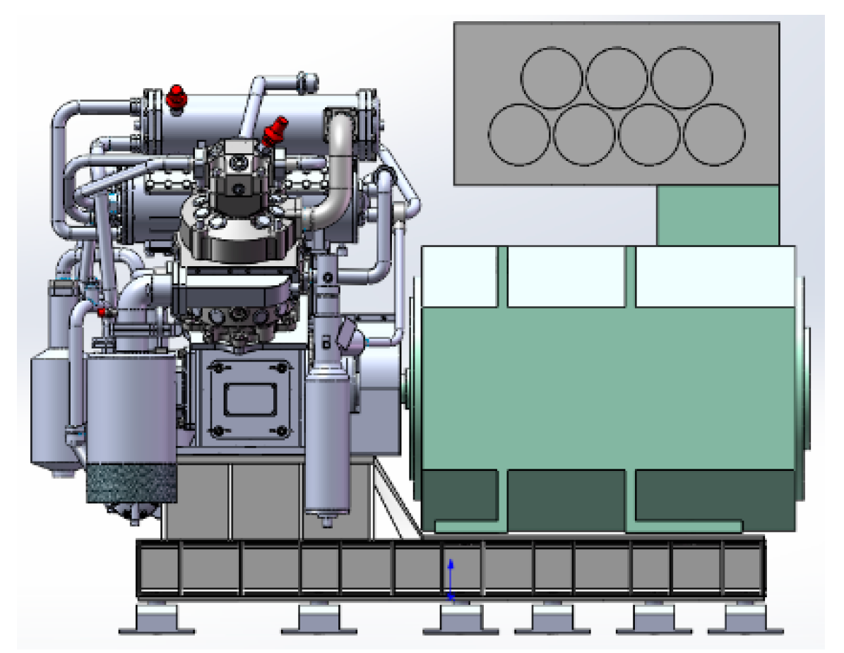
2.1. Vibration Source of Air Compressor

In this paper, a high-pressure air compressor is a reciprocating motion. The working principle of the compressor is that the motor drives the crankshaft to rotate through the coupling. The crankshaft is equipped with two connecting rods to drive the reciprocating movement of two pistons, respectively. So, the gas is compressed step by step. The mechanical energy of rotation is converted into the pressure energy of air. Due to the periodicity of suction and exhaust, the body of the compressor bears the effect of periodic alternating loads [4]. It is the main incentive to induce the vibration of the compressor. Strong vibration brings serious harm to the unit, causing fatigue damage to the structure and accessories. In particular, the connection parts with other parts are easy to loosen and break, which makes the parts damaged prematurely, such as the valve plate of the compressor.
Electromagnetic vibration mainly presents as high-frequency amplitude caused by the motor. On the one hand, these electromagnetic forces produce torque to rotate the motor. On the other hand, they could cause deformation of the stator and vibration of the rotor. This type of noise and vibration is a parasitic effect of the motor. Furthermore, if the motor is rotated, the generated torque will bring related electromagnetic noise and vibration, which is closely related to the electromagnetic parameters and control mode of the motor. In addition, machining errors of the rotor cause mechanical unbalance, including static and dynamic unbalance. It would generate more components in high-frequency response functions.

2.2. Vibration Transfer Path of Air Compressor

Figure 1 shows the three-dimensional diagram of air compressor. In the operating condition of the air compressor, the vibration is inevitably transmitted to the hull through the base structure. Therefore, it is necessary to conduct the vibration test or theoretical analysis of the base to determine the vibration transfer path so as to achieve the goal of vibration reduction of the compressor. Based on the results of the spectrum analysis of the measured data, it can be concluded that there are two transfer paths in the compressor to the base structure, which are as follows:
  • The transfer path of mechanical vibration caused by reciprocating inertia force and the unbalanced moment, which is: shaft—connecting rod—piston—body—support—base structure;
  • The transfer path of electromagnetic vibration led by the air compressor, which is: motor—support—base structure.

3. Analysis of the Vibration Reduction Principle Based on Composite Damping Base

3.1. Application Research Status of Constrained Damping

Constrained damping is composed of the viscoelastic damping layer and the constrained layer, which can be pasted on different structures. In order to reduce the structural vibration response, the phase difference between the internal stress and strain of such a viscoelastic damping material is often considered to dissipate the structural energy because such a damping material undergoes periodic shear deformation when it comes to vibration energy.
The study of damping material or structure can be traced back to 1959. Kerwin used the complex bending stiffness method to carry out the theoretical analysis and prediction of sandwich beam structures [5]. On this basis, Kerwin et al. carried out the relevant research on the damping principle of constrained damping material [6]. A simple theory for calculating the loss factor is put forward, which lays a foundation for scholars to study different damping structures. Based on Kerwin’s work, Ditaranto and Mead studied the motion law of constrained damping structures under arbitrary boundary conditions [7,8]. Considering the tensile deformation of the damping material, the sixth-order partial differential equation of the transverse displacement of the sandwich beam is proposed. Douglas and Yang studied the deformation of passive and semi-active constrained damping beams [9]. They pointed out that the shear deformation energy dissipation of the damping layer accounts for a large proportion of the total energy dissipation. Since then, most theories about constrained damping material or structure have been developed based on the above literature.

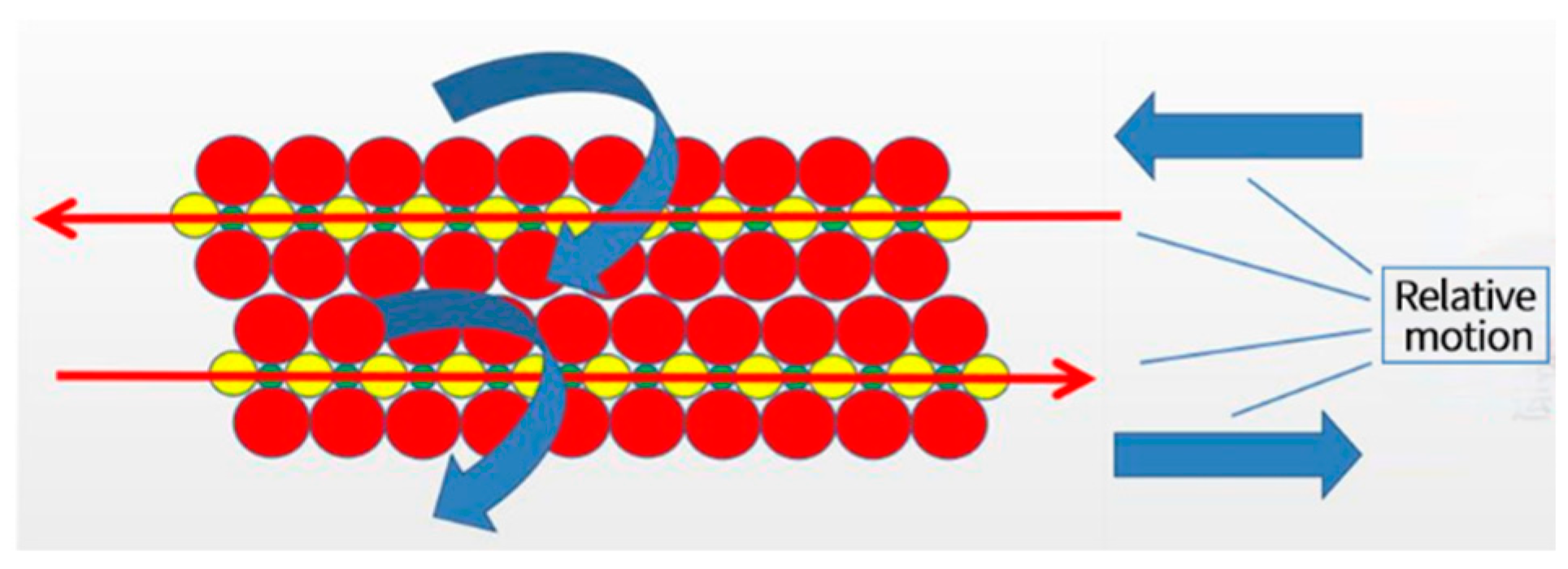
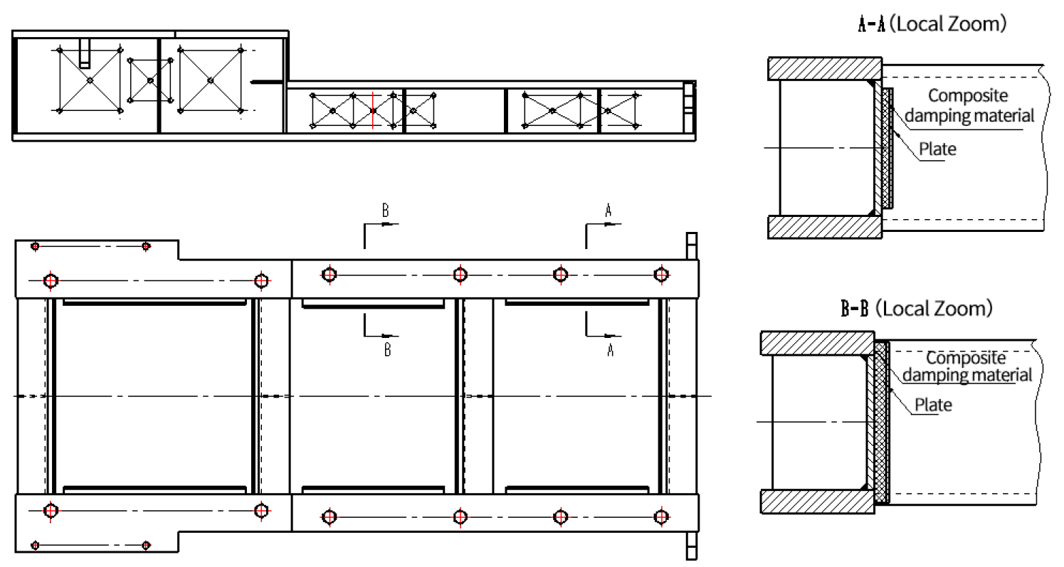
3.2. Vibration Reduction Principle of Composite Damping Base

According to the different composite ways of damping material and matrix, there are usually two forms of damping arrangement for plate structure [10]. One is the free-damping layer arrangement. The other is the constrained damping layer arrangement. If the free damping layer is selected, the damping layer will fall off after a long time of use. Moreover, it is not easy to maintain and other problems. Therefore, as shown in Figure 2, the constrained damping layer layout in this project is chosen. According to the vibration characteristics of the plate structure, the damping material is stuck on the plate, and the metal sheet constraint layer is used to fasten it. When the plate vibrates, the restraint layer produces relative sliding motion, and the super-damping rubber can consume a lot of vibration energy [11]. Thus, the vibration of the plate structure can be reduced.
According to relevant literature, the governing differential equation of structural vibration of composite damping base under external excitation can be obtained as follows [12]:
E 1 v 2 2 u x 2 + E 2 ( 1 + v ) 2 u y 2 2 G h 1 h 2 u ρ P 2 u y 2 + E 2 ( 1 v ) 2 v x y = G ( h 1 + h 2 ) h 1 h 2 w y
E 1 v 2 2 v y 2 + E 2 ( 1 + v ) 2 u x 2 2 G h 1 h 2 v ρ P 2 v t 2 + E 2 ( 1 v ) 2 v x y = G ( h 1 + h 2 ) h 1 h 2 w y
D t 4 w G ( h 1 + h 2 ) h 2 [ ( h 1 + h 2 ) 2 w 2 ( u x + v y ) ] + μ 2 w t 2 = Q i
In the above formulas, one has:
μ = 2 ρ 1 h 1 + ρ 2 h 2 ,   G = G 0 ( 1 + j β ) ,   E = E 0 ( 1 + j η ) ,   D t = 2 E h 1 3 12 ( 1 v 2 )
Among them, u and ν are the displacements in the horizontal plane, w is bending vibration displacement, E is the composite Young’s modulus of composite damping base, E0 is young’s modulus, η is the loss factor, ρ P is the density, v is Poisson’s ratio, μ is the mass density per unit area of composite damping base, ρ 1 and ρ 2 are the material densities of the constraint and damping layers, G is the complex shear modulus, G0 is the shear modulus, β is the loss factor, D t is the bending stiffness, 2 and 4 are the Laplace operator, and Q i is the external excitation force. The vibration transmissibility can be obtained by applying the numerical method to solve Equations (1)–(4). As a result, the appropriate parameters of constraint damping structure can be obtained.
Subsequently, the vibration equation of the composite damping base studied subjected to base excitation load when it is treated as a single-degree-of-freedom system can be defined as [13]:
m d x 2 d t 2 + C ( d x d t d y d t ) + k ( x y ) = 0
y = Y sin ( ω t )
In Equations (5) and (6), m is the mass of the overall structure of the system; C is the damping, k is the spring stiffness, y is the base excitation load, and Y is the excitation amplitude of y .
The solution of such a structure can be assumed with x = B sin ( ω t α ) . Here, B is system amplitude, which has the following expression:
B = Y 1 + 4 D 2 η 2 ( 1 η 2 ) 2 + 4 D 2 η 2
In Formula (7), D is the damping ratio. If η = 1, the system reaches to resonate state. At this time, the damping ratio is D ≠ 0. Then, B can be obtained as:
B = Y 1 + 4 D 2 2 D
As D becomes large, β will be decreased, and the system amplitude B will also be reduced. In practical engineering, the damping ratio of steel is D = 0.002, β = 250. And the damping ratio of steel structure system D = 0.01~0.02, β = 25~50. In the absence of external damping, it can be found that the resonance amplitude caused by the excitation of the vibration source is very large.

4. Influence of Different Materials on Vibration of Composite Damping Base

The different damping material was added to the same part for dynamic testing respectively. No damping material is added to sample 1, EPDM (Ethylene-Propylene-Diene Monomer) is added to sample 2, IIR (Isobutylene Isoprene Rubber) is added to sample 3, and super damping rubber is added to sample 4. Figure 3 gives the test site diagram of the components of the composite damping base using the shaker table. The effects of filling different damping materials were tested on natural frequency, dynamic response, damping performance and dynamic transfer rate of such a base structure. The damping capacity of the structure after filling the material is evaluated objectively. It should be noted that the influence of the operation mode of the compressor, the thermodynamic and gas dynamics on the vibration properties of the composite damping base is neglected.

4.1. Test Method

(1)
Preliminary test of the natural frequency of specimens based on the hammer method
Firstly, the modal test of base parts filled with different damping materials is carried out by the hammer method. Pulse excitation is applied to the test point by force hammer, and a vibration response signal is obtained by the acceleration sensor. The peak of FRF (frequency response function) can be obtained by identification. Each order natural frequency of the component is preliminarily identified.
(2)
Measurement of natural frequency and loss factor coefficient of specimens based on the method of the sinusoidal frequency sweep
The natural frequencies are obtained by the hammering method. Moreover, sinusoidal frequency sweep test is carried out near each order’s natural frequency. After setting the frequency sweep rate, the shaker is used to carry out the frequency sweep test under excitation. After obtaining the three-dimensional waterfall diagram of the response data, the natural frequencies and loss factor coefficients of the samples with different filling materials are accurately obtained by using the peak value method and the half-power bandwidth method.
(3)
Dynamic response test of the specimen under resonant excitation
The accurate natural frequencies of each order are obtained according to the frequency sweep mode. Moreover, the shaker is used to excitability each natural frequency at a certain amplitude so that the specimen reaches the resonance state of natural frequency. After the vibration is stabilized, the response data of the specimen in a resonant state are recorded and extracted.
(4)
Dynamic response test of the specimen under random excitation
According to the given acceleration power spectrum of random excitation, the FRF curve of the specimen is obtained by the shaker table test. The damping performance of samples filled with different damping materials is evaluated by comparison.

4.2. Test Process

For the basic specimens filled with different damping materials, the following test procedures are carried out. In this way, the natural frequency, dynamic response, loss coefficient, and other parameters are obtained.
(1)
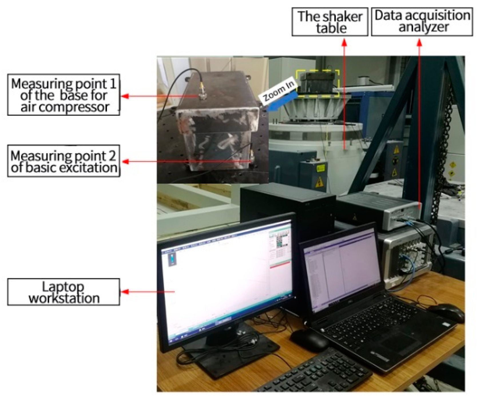
According to experimental requirements, the specimen is installed, and measuring points are arranged.
The base parts are fixed on the shaker table, the specimen is clamped, and the measuring points are arranged.
(2)
The specimen is tested by hammer method.
When conducting a modal hammer test, the key test parameters are set as follows: (1) Sampling frequency: 6400 Hz; (2) Frequency resolution: 0.25 Hz; (3) Window function: the exponential window of force.
(3)
Sweep frequency test is carried out on the specimen.
Based on the modal test results of the hammer method, the first three natural frequencies are obtained. The shaker is used by the frequency sweep method of excitation. Set the following parameters at the beginning of the test: (1) Frequency range: 15~1000 Hz; (2) Frequency resolution: 0.1 Hz; (3) Window function: Hanning window; (4) Basic incentive range: 1g; (5) Sweep speed: 1 Hz/s.
(4)
Constant frequency test is carried out on the specimen.
The first three natural frequencies are selected as fixed excitation frequencies. Under the excitation amplitude of 1g and 3g, the specimens reached the first three order resonance states, respectively. After the structure reaches a steady state, the response data is collected. Moreover, the response test time is set to 30 s.
(5)
Random excitation test is carried out on the specimen.
Random excitation is carried out by a given power spectral density of acceleration. Random excitation test is carried out by shaker table. The response curve of the specimen is obtained in the frequency domain.

4.3. Test Results

(1)
Natural frequency of specimen obtained from modal test by hammering method
The frequency sweep experiments of undamped materials, EPDM, IIR, and super-damping rubber were carried out. The first three order natural frequencies and loss factor coefficients of specimens can be identified and recorded in Table 1.
(2)
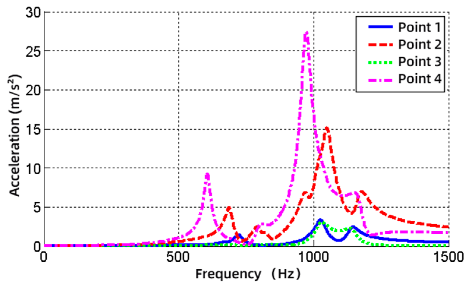
Test results of the dynamic response of specimen under resonant excitation
The response results of the first three orders of the specimen under the excitation amplitude of 1g and 3g are shown in Table 2. Moreover, the vibration isolation effect is shown in Table 3.
(3)
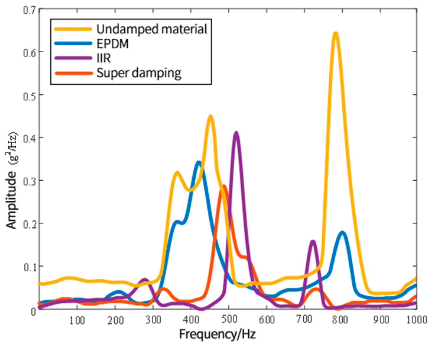
The shaker table is used to test the dynamic response of four types of specimens with different damping materials under random excitation.
The vibration response spectrum obtained by random excitation is shown in Figure 4. Under random excitation, the response results of the first three peaks are identified for the four specimens, as shown in Table 4.

4.4. Comparison of Different Damping Materials in Composite Damping Base

(1)
The test results of different specimens are compared and sorted according to the loss factor coefficients. The loss factor coefficient of the specimen filled with supper damping rubber is the highest. IIR is next, and EPDM is poor.
(2)
Through comparative analysis of resonance response test results of specimens filled with different damping materials, the following conclusions can be drawn. The specimen filled with supper damping rubber has a better vibration suppression effect.
(3)
By analyzing the response data of the first three peaks of the four specimens under random excitation, the following conclusions can be drawn. In most cases, the specimen filled with supper damping rubber has the best damping effect.

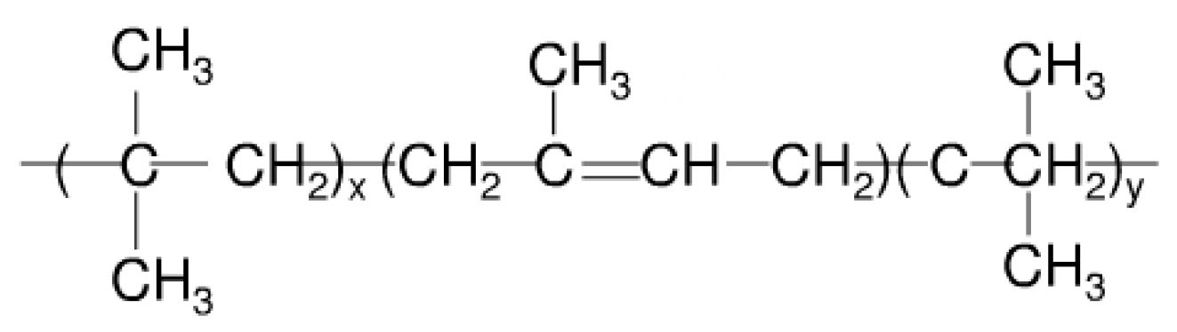
5. Vibration Reduction Mechanism of Super Damping Rubber

The method of vibration reduction here is to use super damping rubber to absorb the vibration energy of the composite damping base of the air compressor because the super damping element in this damping rubber has larger side chain groups in its molecular formula. The frictional resistance is generated between them as chain macromolecules moving. Therefore, the deformation will change more slowly than the external stress when the super damping element is subjected to external vibration. The deformation lags the strain. This kind of lag is obvious at certain temperatures and frequencies.
The super damping element has a good damping effect. Because viscoelastic materials convert vibrational energy into thermal energy consumption. The damping principle is related to the mechanical relaxation of materials. The polymer material has the characteristics of high molecular weight, long molecular chain, easy to curl, and intertwining with each other. When it stretches, the external force does work on the viscous material. One part is used to change the conformation of the molecular segment. The other part is used to overcome the friction of the moving segment. When it retracts, the chain of molecules that stretches out before curls up. The system does work outward, and the molecular chain still must overcome frictional resistance as it curls.
Super damping unit is the product of copolymer modification which mixed isobutene and a small amount of isoprene. Its basic structure is shown in Figure 5 and Figure 6.
The molecular chain structure of super damped element contains many methyl groups. The steric hindrance effect of these methyl groups makes their molecular chain segments have great elastic hysteresis, energy dissipation, and damping effects. Macroscopic performance is high damping. Its advantages are as follows:
  • The molecular chain structure is close. And the air tightness is very good;
  • The unsaturated degree is very low, and the structure is stable. It has good heat resistance and aging resistance;
  • It is difficult to crystallize at low temperatures, so the cold resistance is very good.
The lateral wall of the base body with composite damping element could attenuate the transmitted vibration rapidly. It could reduce the influence of unbalanced reciprocating inertia force and reciprocating inertia moment on the base during the operation of the air compressor. This method can effectively reduce the vibration transmission of the air compressor to the installed foundation. Meanwhile, the service life of vulnerable parts of the air compressor is prolonged, and the reliability is improved.
Compared with the existing technology, the new composite damping base can quickly attenuate the vibration effect during the operation of the air compressor. The main advantages are very light additional mass, simple structure, and easy installation. This method will be widely used in the field of noise and vibration reduction of the air compressor.
In order to reduce the vibration of the base, supper damping is added in the engineering to increase the damping ratio D of the system. Supper damping is mainly used in thin-walled structures, which can greatly improve the damping of the whole structure. Moreover, the vibration waveform attenuation does not oscillate. There is no delay in response to vibration in all degrees of freedom, which can reduce vibration in all directions. This method does not need to change the original base structure, so the construction time is reduced. The vibration energy of the base body is converted into the heat dissipation of the damping patch. Figure 7 shows the structure diagram of composite damping base.

6. Harmonic Response Analysis and Vibration Test Verification

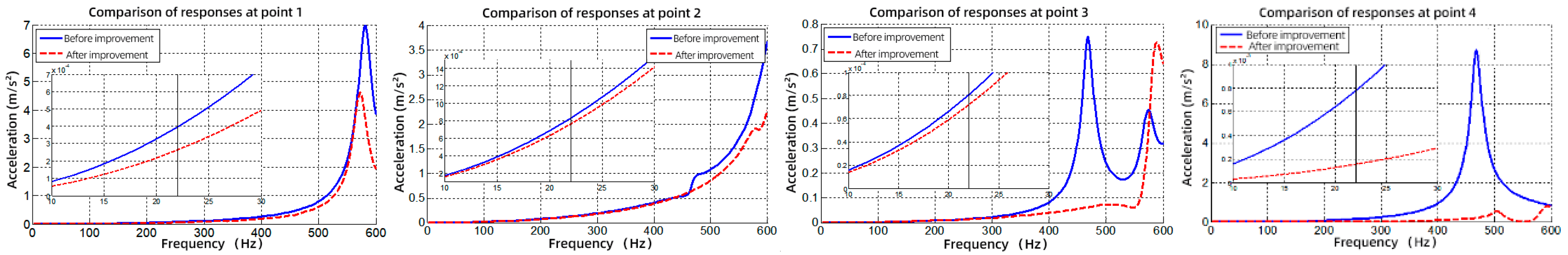
6.1. Comparison and Analysis of Harmonic Response of Composite Damping Base

Harmonic response analysis is used for the steady-state response that a structure is subjected to a sinusoidal variation of load over time.
In the process of analysis, the steady-state forced vibration of the structure is calculated without considering the transient vibration at the beginning of excitation [14]. The purpose of harmonic response analysis is to obtain a curve of response value relative to frequency. It can predict the dynamic characteristics of the structure and verify whether the design can overcome resonance, fatigue, and other harmful effects caused by forced vibration [15,16].
The input of harmonic response analysis is as follows.
  • Harmonic loads of magnitude and frequency such as force, pressure, or forced displacement;
  • Multiple loads at the same frequency may be in one phase or in different phases.
The output of harmonic response analysis is as follows.
  • The harmonic displacement on each degree of freedom is usually in a different phase from the applied load;
  • Various other derived quantities, such as stress and strain, etc.
A reciprocating air compressor is a mechanical device composed of a crank connecting rod mechanism. The role of the periodic alternating load is the main excitation to induce the vibration of the air compressor unit. Therefore, the base body is mainly subjected to cyclic alternating loads. The harmonic response analysis can accurately simulate the vibration response of the base under actual working conditions. Points 1–4 in Figure 2 are response output monitoring points. Moreover, the response of force transfer (Z direction) is shown in Figure 8.
The Z-direction frequency response of monitoring points on the base before and after improvement is compared and analyzed. It shows that the vibration response of the improved base body is significantly lower than that of the original base body under the same load and constraint conditions in Figure 9. Therefore, the improvement scheme is effective.

6.2. Vibration Test Verification

In order to verify the feasibility of the improvement scheme of the base, the vibration test of the air compressor before and after the improvement was carried out. The acceleration level of environmental vibration on the feet of the unit is less than 10 dB compared with the measured value of the working condition. Moreover, the data of the vibration test need not be modified.
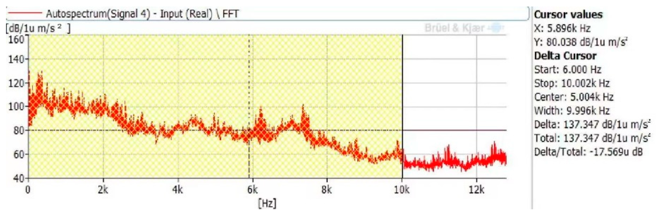
  • The measurement results of the acceleration level of the initial base feet are shown in Figure 10. The average vibration acceleration level is 137.3 dB;
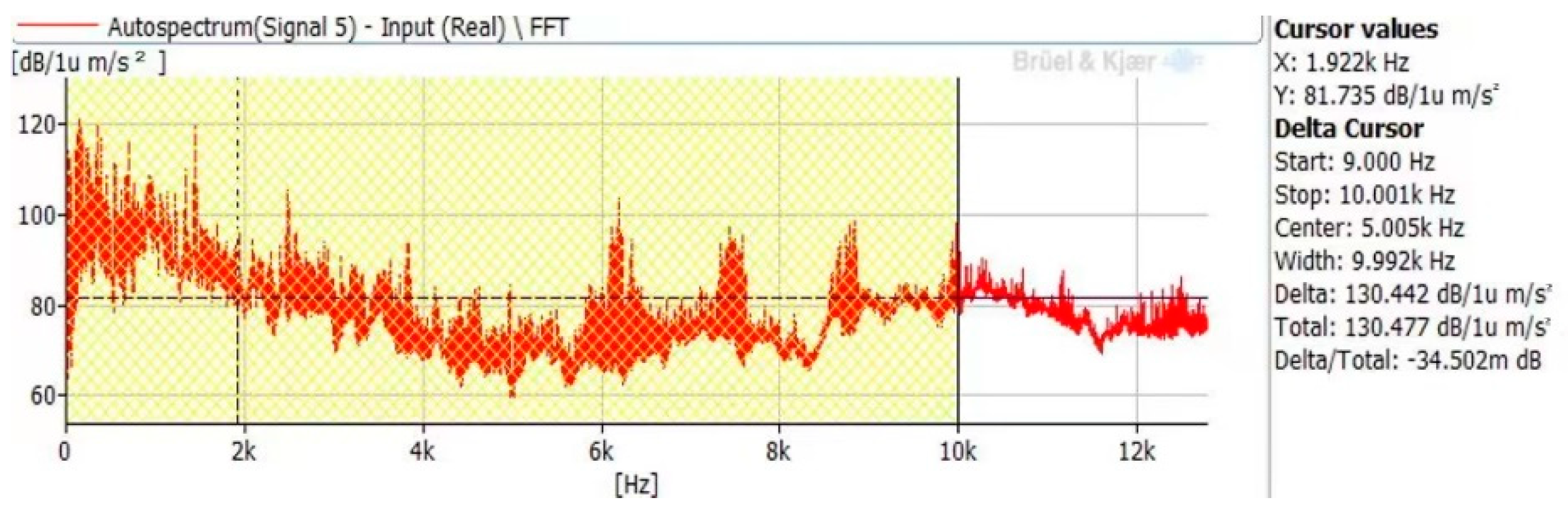
  • The measurement results of the acceleration level of the improved base are shown in Figure 11. The average vibration acceleration level is 130.4 dB.
According to the design requirements of the air compressor unit, the overall vibration acceleration level of the improved base is lower than 131 dB, which meets the design requirements of the air compressor. Therefore, the improvement scheme is effective.

7. Conclusions

In this paper, the feasibility of applying the composite damping base is proven to reduce the vibration of a high-pressure air compressor. To achieve the vibration reduction effect of such a structure, the following conclusions are highlighted:
  • The vibration sources of the air compressor are described. The vibration transfer path from the air compressor to the base structure is analyzed. The vibration energy composition of the base is as follows: the low-frequency vibration is caused by the rotating parts, and the high-frequency vibration is caused by the electromagnetism of the motor.
  • For the base structure, the constrained damping material can be used to absorb its vibration, and the vibration energy can be converted into heat energy by such damping material.
  • Compared to EPDM and IIR, the composite base filled with super-damping rubber possesses the best damping performance since the structure of the molecular formula of such damping rubber has a strong ability to reduce vibration.
  • Finally, vibration test verification data indicates that the application of super damping rubber to the base structure is feasible since the overall vibration acceleration level of the improved base is lower than 131 dB, which meets the design requirements of the air compressor.

Author Contributions

F.Z., writing—original draft preparation, investigation, validation; H.L. (He Li), conceptualization, formal analysis, writing—review and editing, supervision; H.L. (Hui Li), methodology, software, data curation, funding acquisition; D.L., resources, visualization, project administration. All authors have read and agreed to the published version of the manuscript.

Funding

This study was supported by the Fundamental Research Funds for the Central Universities of China (Grant No. N2103026).

Data Availability Statement

It is not convenient for the authors to share the data.

Conflicts of Interest

The authors declare no conflict of interest.

References

  1. Xue, H.Q.; Zhang, G.J.; Hu, L.F.; Zheng, L.P. Calculation and Analysis of Radiation Noise Characteristics of a Type of Marine Air Compressors. J. Noise Vib. Control 2021, 41, 115–121. [Google Scholar]
  2. Xu, H. Research on Structure Vibration and Noise Prediction of Marine Air Compressor. Master’s Thesis, Wuhan University of Technology, Wuhan, China, 2015. [Google Scholar]
  3. Ke, X.Y. Structural Vibration Analysis of Marine Air Compressor and Research on its Vibration and Noise Reduction Technology. Master’s Thesis, Jimei University, Xiamen, China, 2020. [Google Scholar]
  4. Zhu, B.; Zhang, Z.; Zhang, C.; Li, X.; Xing, Z.; Tan, Y. Analysis and Experimental Research of Marine Vertical High Pressure Air Compressor. J. Fluid Mach. 2020, 48, 43–47. [Google Scholar] [CrossRef]
  5. Kerwin, E.M. Damping of Flexural Waves by a Constrained Viscoelastic Layer. J. Acoust. Soc. Am. 1959, 31, 952–962. [Google Scholar] [CrossRef]
  6. Ross, D.; Ungar, E.; Kerwin, E.M. Damping of Plate Flexural Vibrations by Means of Viscoelastic Laminate in Structural Damping; American Society of Mechanical Engineers: New York, NY, USA, 1959. [Google Scholar]
  7. Ditaranto, R.A. Theory of Vibratory Bending for Elastic and Viscoelastic Layered Finite Length Beams. J. Appl. Mech. 1965, 87, 881–886. [Google Scholar] [CrossRef]
  8. Mead, D.J.; Markus, S. The Forced Vibration of a Three-Layer Damping Sandwich Beam with Arbitrary Boundary Conditions. J. Sound Vib. 1969, 10, 163–175. [Google Scholar] [CrossRef]
  9. Douglas, B.E.; Yang, J.C.S. Transverse Compressional Damping in Vibratory Response of Elastic-Viscoelastic-elastic Beams. AIAA 1978, 20, 925–930. [Google Scholar] [CrossRef]
  10. Lu, Y.P.; Everstine, G.C. Vibrations of three layered damped sandwich plate composites. J. Sound Vib. 1979, 64, 63–71. [Google Scholar] [CrossRef]
  11. Johnson, C.D.; Kienholz, D. Finite element prediction of damping in structures with constrained viscoelastic layers. AIAA 1981, 20, 1284–1290. [Google Scholar] [CrossRef]
  12. Singh, S.P.; Gupta, K. Composite shaft rotor dynamic analysis using a layer wise theory. J. Sound Vib. 1996, 191, 739–756. [Google Scholar] [CrossRef]
  13. Kim, W.; Argento, A.; Scott, R.A. Free Vibration of a rotating tapered composite Timoshenko shaft. J. Sound Vib. 1999, 226, 125–147. [Google Scholar] [CrossRef]
  14. Leung, A.Y.; Zhu, B.; Zheng, J.; Yang, H. Two-dimensional vibration by analytic Fourier p-elments. Thin-Walled Struct. 2003, 41, 1159–1170. [Google Scholar] [CrossRef]
  15. Zhang, Q.J.; Sainsbury, M.G. The gale kin element method applied to the vibration of rectangular damped sandwich plates. Comput. Struct. 2000, 71, 717–730. [Google Scholar] [CrossRef]
  16. Alvedid, M.; Enelund, M. Modelling of constrained thin rubber layer with emphasis on damping. J. Sound Vib. 2007, 300, 662–675. [Google Scholar] [CrossRef]
Figure 1. Three-dimensional diagram of air compressor.
Machines 11 00229 g001
Figure 2. Schematic diagram of different layers of composite damping base.
Machines 11 00229 g002
Figure 3. Test site diagram of the components of composite damping base using the shaker table.
Machines 11 00229 g003
Figure 4. Frequency domain responses of four specimens under random excitation.
Machines 11 00229 g004
Figure 5. The basic structural formula of the super damping element.
Machines 11 00229 g005
Figure 6. Molecular and relative motion models of the super damping element.
Machines 11 00229 g006
Figure 7. Structure diagram of composite damping base.
Machines 11 00229 g007
Figure 8. Frequency response at feet of the base.
Machines 11 00229 g008
Figure 9. Comparison of frequency response at monitoring points of the base after improvement.
Machines 11 00229 g009
Figure 10. Vibration acceleration level of feet in the initial state.
Machines 11 00229 g010
Figure 11. Vibration acceleration level of feet on improved base.
Machines 11 00229 g011
Table 1. The first three order natural frequencies and loss factor coefficients of four type specimens.
Damping MaterialsFrequency (Hz)Loss Factor
1st2nd3rd1st2nd3rd
Sample 12763848710.0110.0290.012
Sample 22363387860.0210.0540.023
Sample 32343387400.0240.0600.022
Sample 42243327460.0540.0680.024
Table 2. First three order resonance responses of specimens under different excitation amplitudes.
Damping Materials1g (dB)3g (dB)
1st2nd3rd1st2nd3rd
Sample 114.8713.732.1421.4418.5511.41
Sample 210.298.631.4418.9313.339.94
Sample 36.538.566.9419.2315.0311.91
Sample 45.711.597.9817.1810.733.41
Table 3. First three orders of vibration isolation of specimens under different excitation amplitudes.
Damping Materials1g (dB)3g (dB)
1st2nd3rd1st2nd3rd
Sample 1------
Sample 24.585.100.702.515.221.47
Sample 38.345.179.082.213.526.5
Sample 49.1612.1410.124.267.828.00
Table 4. Results of the peak responses under random excitation.
Damping MaterialsPeak (Hz)Response (g2/Hz)
1st2nd3rd1st2nd3rd
Sample 13744658050.330.470.65
Sample 22274387990.040.340.22
Sample 32865237090.060.430.18
Sample 42265047240.050.270.05
Disclaimer/Publisher’s Note: The statements, opinions and data contained in all publications are solely those of the individual author(s) and contributor(s) and not of MDPI and/or the editor(s). MDPI and/or the editor(s) disclaim responsibility for any injury to people or property resulting from any ideas, methods, instructions or products referred to in the content.

