Article

Experimental Study on Tribological and Leakage Characteristics of a Rotating Spring-Energized Seal under High and Low Temperature

1
College of Mechanical and Electrical Engineering, Beijing University of Chemical Technology, Beijing 100029, China
2
Division of Machine Elements, Luleå University of Technology, 97187 Luleå, Sweden
*
Author to whom correspondence should be addressed.
Machines 2023, 11(2), 221; https://doi.org/10.3390/machines11020221
Submission received: 15 December 2022 / Revised: 29 January 2023 / Accepted: 30 January 2023 / Published: 3 February 2023
(This article belongs to the Special Issue Selected Papers from CITC2022)

Abstract

:
A spring-energized seal, whose PTFE plastic shell has excellent self-lubrication and a low temperature stability, is used widely in liquid fuel valves’ rotating end-face seals. However, in practical application, temperature has a larger effect on not only the physical and tribological properties of materials, but also on the leakage performance of spring-energized rings. Thus, a high and low temperature sealing test of the spring-energized seal that applies to an engine was carried out. In this paper, the leakage characteristics, friction torque and wear characteristics of a spring-energized ring under different temperatures were studied. The friction torque at high temperature was less than that at normal temperature, and a low temperature could effectively reduce the wear amount of PTFE material. In order to study the influence of temperature on PTFE filled with graphite, the friction and wear test of PTFE-2 was carried out. The results showed that the amount of wear of PTFE-2 was only 27.8% of that at the normal temperature but the friction coefficient was three times larger when the temperature was −45 °C.

1. Introduction

The spring-energized seals is widely used in aviation, aerospace, shipbuilding and nuclear power due to its polytetrafluoroethylene (PTFE) shell that has the advantages of a low-temperature stability, low coefficient of friction, wear resistance, reliable high-speed surface dynamic performance, stable chemical properties and radiation resistance [1,2]. In military equipment, new energy equipment and deep-sea equipment such as high-end precision equipment with high-reliability and life requirements, about 80% of soft material seal failures are related to friction and wear [3,4]. The low hardness, low wear resistance and low creep resistance of pure PTFE materials severely limit their further development [5,6,7], so researchers have enhanced the surface activity, heat resistance, mechanical strength and wear resistance of PTFE materials [8] through surface modification [9], blend modification [10] and filler modification [11,12,13,14,15], among which filling is one of the most commonly used methods because of its simple operation and significant effect [16], and suitable fillers can greatly improve the tribological and sealing properties of PTFE materials [5].
The wear mechanism of composite materials is influenced by their surface morphology, the operating environment (lubrication, temperature, load, speed) and the material of the contact pair [17]. From the material side, compared with rubber material, PTFE has a stronger stability at low temperature and lower friction coefficient. B. Tan [2] developed a calculative model to study the isothermal viscoelastic dynamic response of PTFE seals under a harmonic input and static preload from an ideal rigid relative surface and found that the surface separation of PTFE seals occurred even under small-amplitude harmonic vibrations due to a delayed recovery at low frequencies, a viscoelastic damping at high frequencies and given static preload thresholds above which separation did not occur. K. Li [18] studied and determined the separation distance and the maximum static friction of a spring-energized seal in a mechanical seal, which could be used to study the mechanical behavior of the spring-energized seal in the process of antivibration and microscale motion, and the accuracy of the simulation model was verified by experiments. T.-C. Huang [19] used the modified Archard model to evaluate the wear amount of spring-energized polytetrafluoroethylene (PTFE) seal, and the geometric size of the result was almost the same as that of the test sample, proving that wear caused the contact pressure peak to decrease gradually with the number of cycles.
For PTFE materials, researchers have investigated the effects of filler mixing time [20], filler particle morphology [21], filler content [22], filler material [11,23,24,25] and filler size [26] on the friction coefficient, wear amount, Young’s modulus, creep properties, film-forming stability and film-forming ability of PTFE materials. L. Gao [20] found that the mixing time affected the mixing temperature between the filler and PTFE, softening the base material, the softening of the base material being due to frictional heat leading to uneven stress, the occurrence of adhesive wear being unfavorable to the stability of the transfer film and increasing the wear rate. K. Mazur [21] discovered that filling larger particles with elongated shapes increased the Young’s modulus of PTFE significantly. A. Sonawane [22] filled carbon into PTFE and noticed that the wear rate of PTFE with a 35% carbon mass fraction was significantly less than PTFE with 25% carbon. Z. Lin [11] compared nanoalumina particles, micron-size brass particles, molybdenum disulfide, graphite flakes and short-cut carbon fibers filled with PTFE materials and proposed that the types and properties of fillers determined the friction film generation ability of PTFE composites. T. Xie’s [24] experiments demonstrated that adding LaF3/CeF3 into PTFE could reduce the transfer film thickness and increase the transfer film coverage to form a thin and uniform transfer film. X. Li [25] filled PTFE with a Ni-Ti alloy to enhance the frictional wear properties and creep performance of PTFE composites. It was pointed out that adhesive wear was the main wear mechanism of pure PTFE material, the added particles could prevent the formation of large PTFE fragments and the abrasive particles could easily enter around the filler particles to reduce wear. C. Visconte [27] proposed an experimental method to measure the leakage path thickness when the leakage was small and controllable and numerically simulated the measured leakage path; the experimental and simulation results matched well.
However, there are few experimental studies on the friction, wear and leakage characteristics of the spring-energized seal in the form of an end seal. This paper compares the foreign commercial spring-energized seal and the domestic self-produced spring-energized seal in high and low temperature sealing tests, combined with a material friction and wear test, to study the leakage characteristics and friction and wear characteristics of the spring-energized seal in static and rotating states and provide theoretical and experimental support for the application of low friction and low wear of the spring-energized seal.

2. Materials and Methods

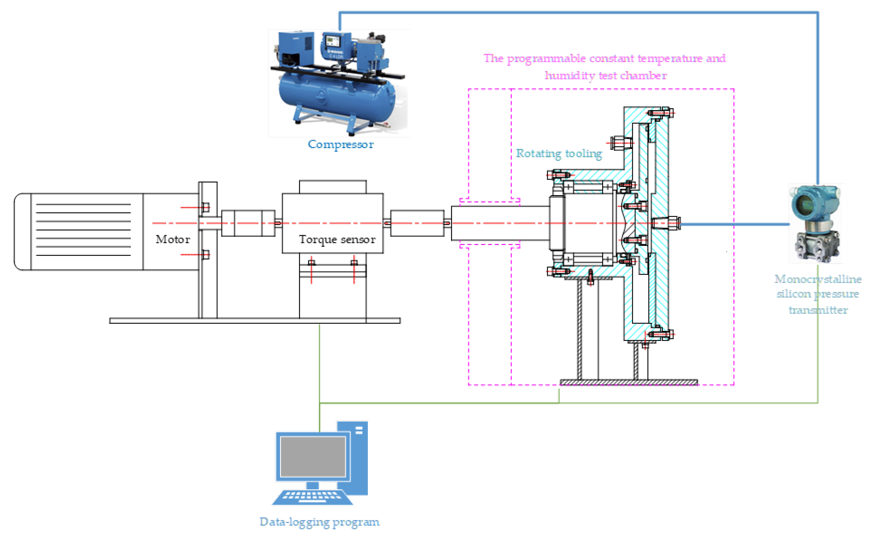
2.1. Wide-Temperature-Range Friction System and Seal Test Apparatus

In this paper, a programmable constant temperature and humidity test chamber and torque sensor were added to the traditional-face rotary seal device to form the following spring-energized seal’s wide-temperature-range friction-torque measurement system. The seal friction system shown in Figure 1 was used to test the seal leakage and friction torque of the spring-energized seal under different working conditions. The motor provided power to drive the seal test apparatus. The compressor provided a sealing pressure and served as an external sealing cavity; the volume was 30 L. The programmable constant temperature and humidity test chamber was used to set the temperature of the sealing experiment. The seal test apparatus provided the groove and the opposite surface for the seal. The torque sensor was used to measure the friction torque of the spring-energized seal. A monocrystalline silicon pressure transmitter was used to measure the pressure of the sealing cavity. A data-logging program was used for recording test data.
The seal test apparatus shown in Figure 2a was used to simulate the assembly of the seal and to investigate the leakage characteristics and frictional wear performance of the spring-energized seal ring. Since the seal ring had three kinds of configurations, the apparatus was designed with removable grooves and counterabrasive gaskets shown in Figure 2b. The air inlet could be adjusted to ensure that the seal ring’s opening direction was the same as the air inlet direction. The surface roughness of the sealing surface was Ra = 0.001 μ m. The surface roughness was controlled by machining precision and detected by a roughness meter. By controlling the clearance between the gasket and the groove, the compression amount of the spring-energized seal was adjusted to ensure the seal gasket contact and aid in static and dynamic sealing. In case of serious wear, such as scratches, holes and deformations leading to seal failure, the gasket could be replaced.

2.2. Sealing Ring and Materials

The sealing ring used in the test was provided by Aerospace Research Institute of Materials and Processing Technology; its working principle is shown in Figure 3. There were three kinds of sealing rings with the same cross section’s size but different groove diameters, whose sizes are shown in Table 1.
The shell material of the seal ring was PTFE filled with graphite particles to improve its wear resistance. The graphite particle size of PTFE-1 was 80 μ m, and the graphite particle size of PTFE-2 was 20 μ m. The spring material of the seal was 316 stainless steel and the U-spring was made of metal plates that had been slotted and bent. The compression stiffness coefficient of the U-spring per unit length was 0.52 N·mm 2 . The properties of each material of the seal are shown in Table 2. The friction torque and surface topography of the seal ring was measured.

2.3. Methods

The aim of this work was to reproduce the conditions for a seal placed in the valve at different temperatures. It was required that the leakage rate of the spring-energized seal be less than 0.2 kPa·min 1 in a 30 L sealing cavity, within a 10 kPa initial sealing pressure, at normal temperature and at the compression quantity. Moreover, the friction torque of seal 1 should be less than 3.5 N·m when rotating, and the friction torque of seals 2 and 3 should be less than 0.9 N·m. Figure 2 shows the position of the seal ring in the valve line at a speed of 20 rpm. The relationship between the tribological characteristics and temperature was studied by a PTFE pair-grinding experiment.

2.3.1. Test Methods

We adjusted the compression of the spring-energzied seal ring by installing a metal thin washer with a thickness range of 0.01~0.5 mm in the groove and gasket parts. The programmable constant temperature and humidity test chamber controlled the ambient temperature, and the sealing torque test needed to be carried out after holding for 4 h at the specified temperature; the low one was −45 °C and the high one was 65 °C. The motor speed was stable at 20 rpm, and the compression was adjusted according to the leakage and torque at room temperature. If the leakage amount was too large, the compression amount was increased, and if the friction torque was too large, the compression was reduced.
After testing the seal on the wide-temperature-range friction system, in order to continue to investigate the effect of temperature on the PTFE material, a pin-disc experiment was carried out on the UMT-4 TriboLab. The pin had a diameter of 5 mm, a length of 20 mm, was made of PTFE-2 and had a rotational diameter of 25 mm when rubbing against the disc. To achieve the same working conditions (pressure and linear velocity) for the PTFE sample as for the seal ring test, the test conditions for the tribological characteristics of PTFE filled with graphite were a loading of 50 N, a rotating speed of 150 rpm, a running time of 1800 s and temperatures at room temperature and −45 °C.
To ensure the reliability of the experimental results, each set of experiments was repeated three times or more.

2.3.2. Measurement Methods

Material analysis methods: In order to analyze the properties of the seal shell material, the surface elemental composition, filler distribution state and filler morphology of three PTFE materials were obtained by energy dispersive spectroscopy (EDS, S-4700, Hitachi, 1801 Beijing Development Building, No.5 North Dongsanhuan Road, Beijing, China, secondary electron image resolution: 1.5 nm—15 kV; 2.1 nm—1 kV). After obtaining the filler element composition, the filler content and thermal properties of the PTFE materials were analyzed by a thermogravimetric analysis (TGA) and differential scanning calorimetry (DSC, TGA/DSC3+, METTLER, Nitrogen atmosphere, 0~900 °C).
Surface topography measurements: A computer numerical control 3D optical measuring instrument was used to perform the surface measurements. The surface topography of a sample was derived by adjusting the magnification of the eyepiece and objective lens. The magnification of the instrument was 83, 500 and 1000 to observe the sample surface. A roughness meter was used for surface roughness measurement (stylus profilometer by Wuxi Dumon Instrument Manufacturing Co., Ltd, No.30, Qunxing Road, Meicun Industrial Park, Xinwu District, Wuxi, China, TR200).
Leakage of seal: A monocrystalline silicon pressure transmitter was connected between the compressor outlet of the air compressor and the rotary tool through a hose to measure the pressure change of the sealed cavity and measure the leakage according to the pressure reduction. As shown in Figure 1, the monocrystalline silicon pressure transmitter had a range of 50 kPa and an accuracy of 0.01 kPa.
Wear measurements: A dial indicator was used to measure the wear of the PTFE-2 sample with an accuracy of 0.001 mm. The amount of PTFE wear could be determined from the height change of the PTFE-2 sample before and after wear. Three fixed points were selected to take the average value for each measurement. Before each measurement, the sample was cleaned by alcohol on the surface, dried in a drying oven at 80 °C for half an hour and then allowed to come to room temperature for measurement.

3. Results and Discussion

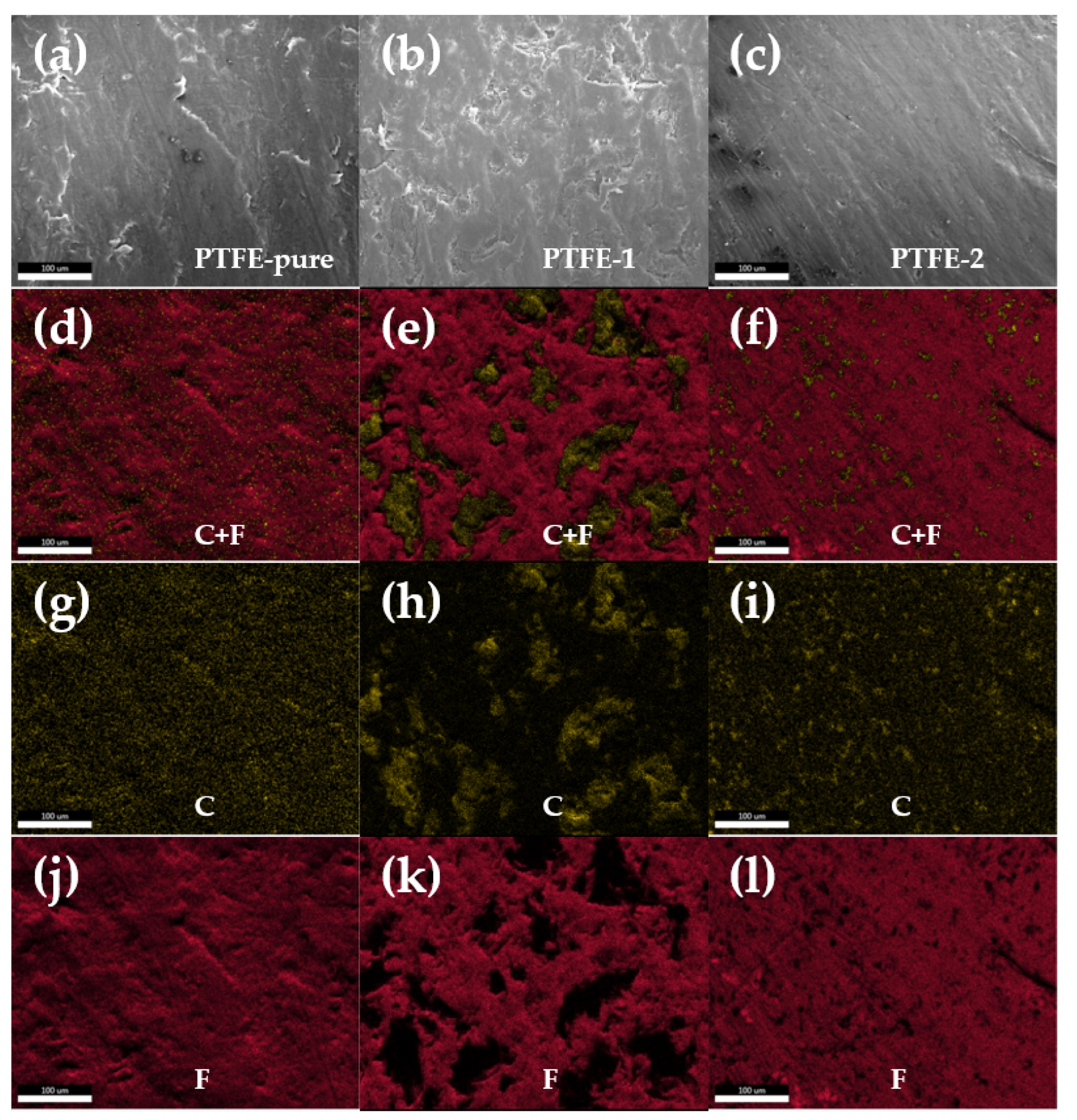
3.1. Shell Material Composition and Filler Shapes

The microscopic morphology and EDS results of the three seal shell materials, pure PTFE, PTFE-1 and PTFE-2, are shown in Figure 4. The distribution of PTFE on the surface of the three materials is shown in Figure 4j–l, while the distribution of C element in Figure 4d–f proves that the fillers of PTFE-1 and PTFE-2 were graphite particles. Comparing the morphology and size of the graphite fillers in PTFE-1 and PTFE-2 with Figure 4g–i, the graphite particles in PTFE-1 were larger, with a particle size of approximately 80 μ m, cloud-shaped and uniformly distributed; the graphite particles in PTFE-2 were smaller, with a particle size of approximately 20 μ m, star-shaped and uniformly distributed.
Figure 5 shows the thermal gravimetric analysis results, differential scanning calorimetry results and differential thermal analysis results for the three shell materials within the nitrogen atmosphere, respectively, with a heating rate of 10 °C/min and a temperature range of 0~900 °C. The PTFE of the three materials in Figure 5a started to decompose and gasify at around 475 °C. The pure PTFE completely gasified at around 620 °C with no residual material. PTFE-1 ended up gasifying at around 610 °C. The mass of ungasified graphite filler was 14.2%. PTFE-2 ended at around 615 °C and the mass of ungasified graphite filler was 8.0%. The graphite filler’s mass in PTFE-1 was larger than in PTFE-2. Figure 5b shows the thermal difference analysis curves for the three materials, with the heat absorption peak at around 575 °C corresponding to the decomposition range of PTFE in Figure 5a, and the DTA curve with only one heat absorption peak, indicating that the chemical structure of the three materials remained stable from 0 to 475 °C and that the PTFE did not crystallize. Figure 5c shows the DSC curves for the three materials. All three curves followed the same trend, with their glass transition temperatures around 130 °C. The heat absorption peak at around 328 °C indicated that the PTFE material melted. After that, the curve rose and at a temperature of 475 °C, the curve changed from heat absorption to exothermic, and the PTFE started to decompose and gasify at a temperature of about 575 °C. There was no significant difference in thermal decomposition performance between PTFE-1 and PTFE-2.

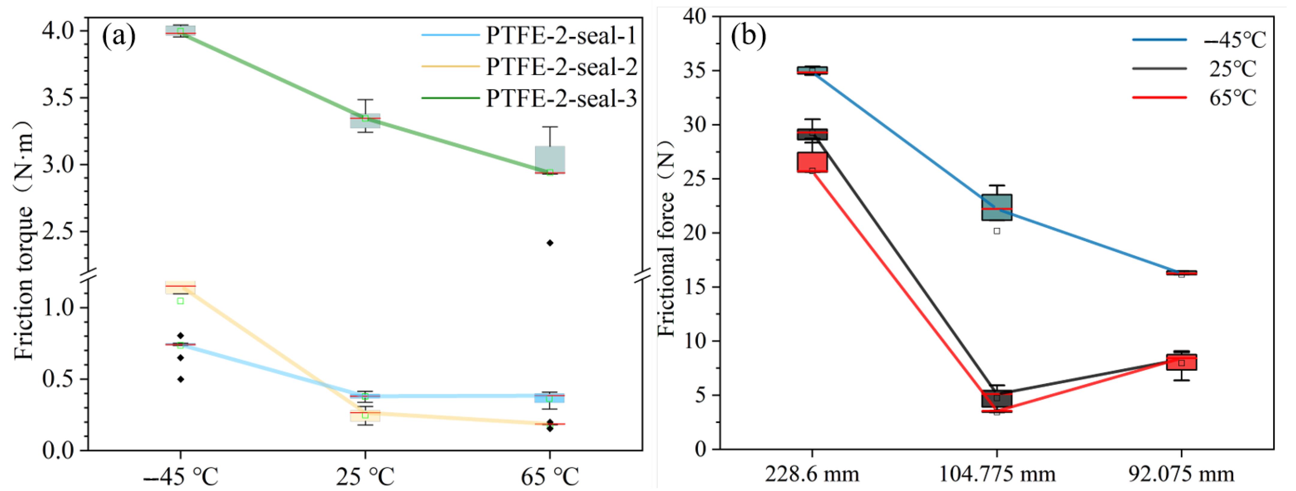
3.2. Friction Torque of Seal Ring

We adjusted the compression of the spring’s energy storage’s seal ring by installing a metal thin washer with a thickness range of 0.05~0.5 mm in Figure 2a. The compression of seal-1, seal-2 and seal-3 was 0.15 mm, 0.16 mm and 0.34 mm.
Temperature impact: Figure 6 shows the relationship between friction torque and time of the PTFE-2-seal-3 seal ring. It can be seen that the friction torque of the seal ring fluctuated in the process of rotation. Compared with 25 °C and 65 °C, the friction torque fluctuation of the sealing ring was larger at −45 °C, indicating that the stability of the sealing ring was slightly decreased at low temperature, and the friction stability of the sealing ring was better with the increase of temperature. To further discuss the effect of temperature on the frictional torque of the seal ring, Figure 7a shows the variation of frictional torque with temperature for three different sizes of seal ring with PTFE-2. The friction torque of all three seals decreased with the increase of temperature, and the friction torque became dramatically larger at −45 °C, as shown in Figure 7a. The drop in temperature led to a shrinkage of the structure and a change in material properties. Combined with the higher leakage at low temperatures in Section 3.3 and the higher friction coefficient at low temperatures in Section 3.5, we can see that the contact pressure at the sealing surfaces was reduced and the frictional force and frictional torque were increased [21].
Size impact: The sealing ring’s frictional force curve in Figure 7b was obtained by dividing the friction torque by the corresponding radius; it can be seen that the diameter size influenced the ability of the seal ring to resist temperature changes. When the temperature was constant, the friction force of the sealing ring decreased with the decrease of the diameter, which was particularly obvious at −45 °C. In addition, the friction force of seal-1 was least affected by temperature: in the range of −45 °C to 65 °C, the friction force of seal-3 was 29.3 N (−12.3~19.5%), the friction force of seal-2 was 4.8 N (−27.1~402.1%) and the friction force of seal-1 was 8.3 N (−3.6~95.2%). In fact, the compression of seal-1 and seal-3 was 0.15 mm and 0.34 mm, respectively, measured during the experiment, indicating that the diameter size variation changed the mechanical properties of the seal ring, resulting in a seal ring with the same cross section requiring different compression values to achieve the sealing requirements. Combined with the leakage in Section 3.3, it can be seen that a large size seal ring required a high compression to provide good sealing performance.
Material impact: Figure 8 shows the variation curve of friction torque with temperature for the seals of PTFE-1 and PTFE-2 shell materials. Compared to PTFE-2, the PTFE-1 material seal ring had a better temperature change resistance, with a friction torque variation range of 0.64~0.53 N·m in the −45~65 °C temperature range, while the PTFE-2 seal ring had a torque variation range of 0.74~0.32 N·m. The PTFE-1 seal ring had a lower friction torque at low temperature, while the PTFE-2 seal ring had a much lower frictional torque than PTFE-1 seals in the temperature range 25~65 °C. It was preliminarily believed that the cloud-shaped filler in PTFE-1 had more advantages than the star-shaped filler in PTFE-2 in the friction process at −45 °C.

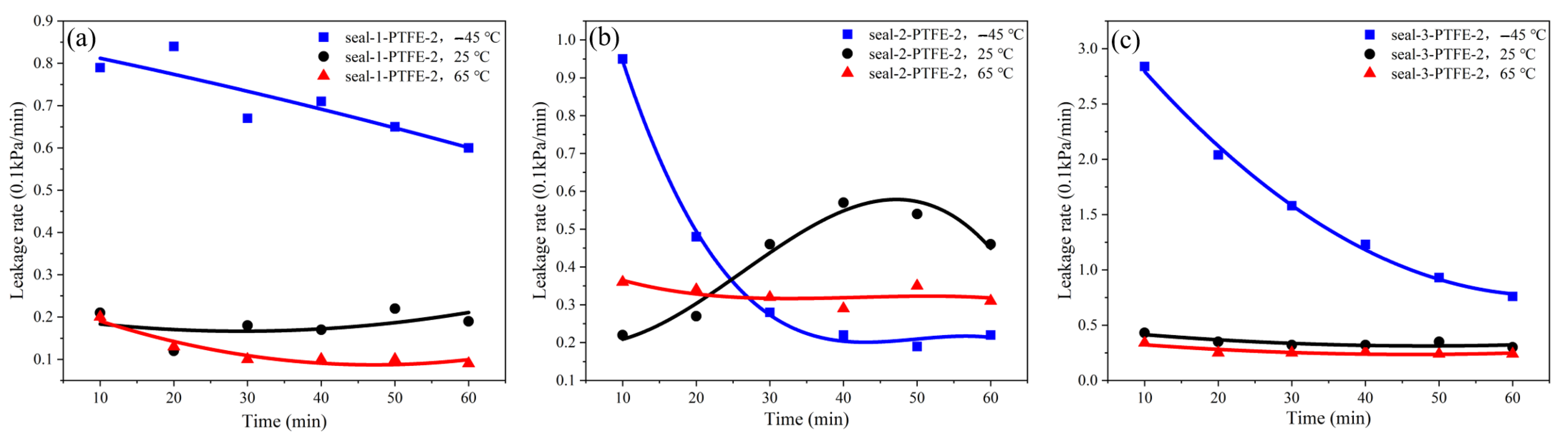
3.3. Leakage of Seal Ring

Temperature impact: It can be seen from Figure 9a–c that the higher the temperature, the more stable the seal, and the leakage rate of the seal at low temperature was obviously 2–5 times higher than that at room temperature and high temperature. The leakage rate at low temperature decreased rapidly with time, which was due to the larger leakage rate in the early stage leading to an excessive pressure drop in the sealing cavity, and the seal leakage rate decreased when the pressure in the sealing cavity decreased.
As shown in Figure 8 and Figure 10, on the whole, the sealing performance of the PTFE-1 seal ring was more stable, the trend of friction torque and leakage rate affected by temperature was consistent with that of the PTFE-2 seal ring, but the change was smoother. The friction torque of the PTFE-1 seal ring at low temperature was greater than that of the PTFE-2 seal ring, while the friction torque at 25 °C and 65 °C was less than that of the PTFE-2 seal ring. At the same temperature, the leakage rate of the PTFE-1 seal ring was smaller than that of the PTFE-2 seal ring, and its leakage rate at low temperature was much smaller than that of the PTFE-2 seal ring.

3.4. Surface Topography

The spring-energized seal worked in close contact and relative motion with the gasket, leaving a clear abrasion mark on the gasket, as shown in Figure 11. The gasket wear mark and the seal contact surface matched very well when enlarged. The seal contact surface was observed to have uneven wear on the inside and outside of the contact surface, with the inside of the contact surface being smoother than the outside. Similarly, a uniform transfer film was formed on the inside of the gasket wear marks, which showed that the inner side of the contact surface was under more pressure than the outer side during operation.

3.4.1. Gasket

Comparing Figure 12a,c, the wear marks of the gasket were mainly composed of the change of its surface topography and the transfer of surface material due to the wear of the seal.
Surface topography of gasket: The change of surface topography before and after wear is shown in Figure 12b,d after a magnification of the gasket surface by 1000 times. Compared with the surface before wear, the surface after wear had an obvious color, which was caused by the large amount of frictional heat generated during the relative motion.
Material transfer on sleeve surface: Comparing the wear debris left on the gasket by PTFE-1 and PTFE-2 as shown in Figure 12e,f, it can be seen that the transfer film formed by the material transfer was scraped and stuck in the gasket gap, which was finer and more uniform than the filler on the surface of the seal, and the bonding effect of the wear debris transfer film of PTFE-1 was better than that of PTFE-2.

3.4.2. Seal Ring

Wear of PTFE-2-seal ring: It can be seen from Figure 13a,b that adhesive wear and abrasive wear occurred on the surface of the PTFE-2 sealing ring. There were obvious scratches and adhesive wear debris on the surface of the worn sealing ring. The scratches were the same as those of the gasket in Figure 12e. The surface topography remained the same, and the wear debris was similar to Figure 12f, which may be the same composition.
Wear of PTFE-1 seal ring: Compared with Figure 13a, the PTFE-1 seal ring fillings distributed on the surface are cloud-shaped in Figure 14a, while the surface fillings of the PTFE-2-seal ring are star-shaped. The polymerized effect of the filler of the PTFE-1 seal ring after wear was better than that of the PTFE-2-seal ring, and the filler was the main wear object. It can be seen from Figure 14f that there was typical fatigue wear. Compared with abrasive wear, the wear rate of fatigue wear was smaller and the friction was more stable, so the friction of the PTFE-1 material with cloud filler was more stable, and the sealing effect of the PTFE-1 seal ring was also better.

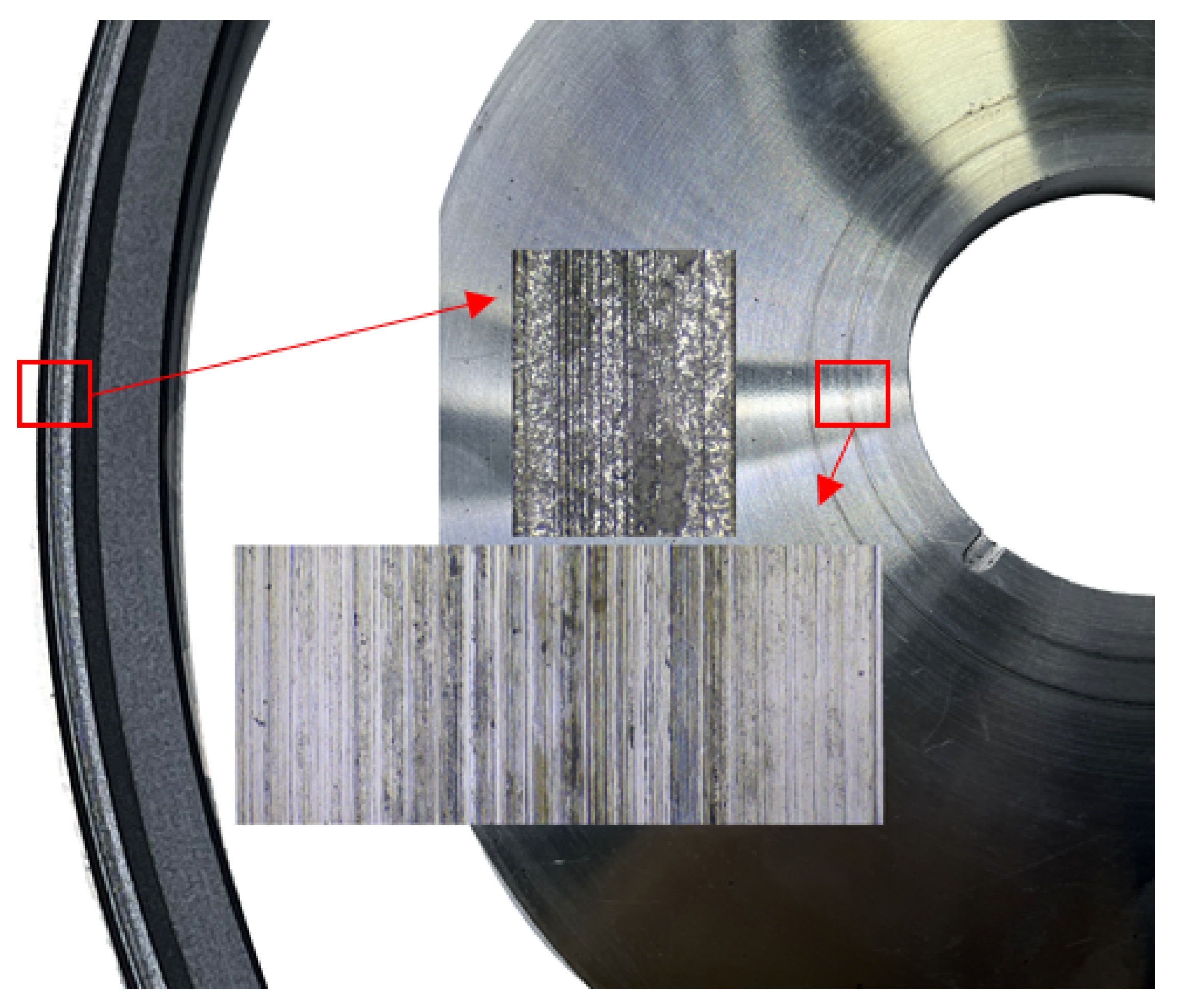
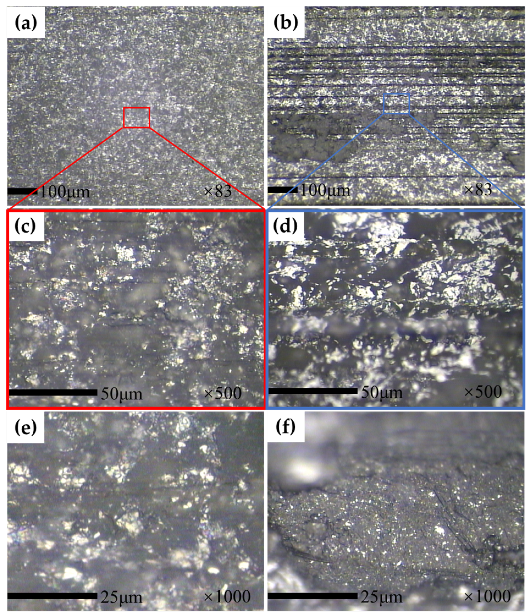
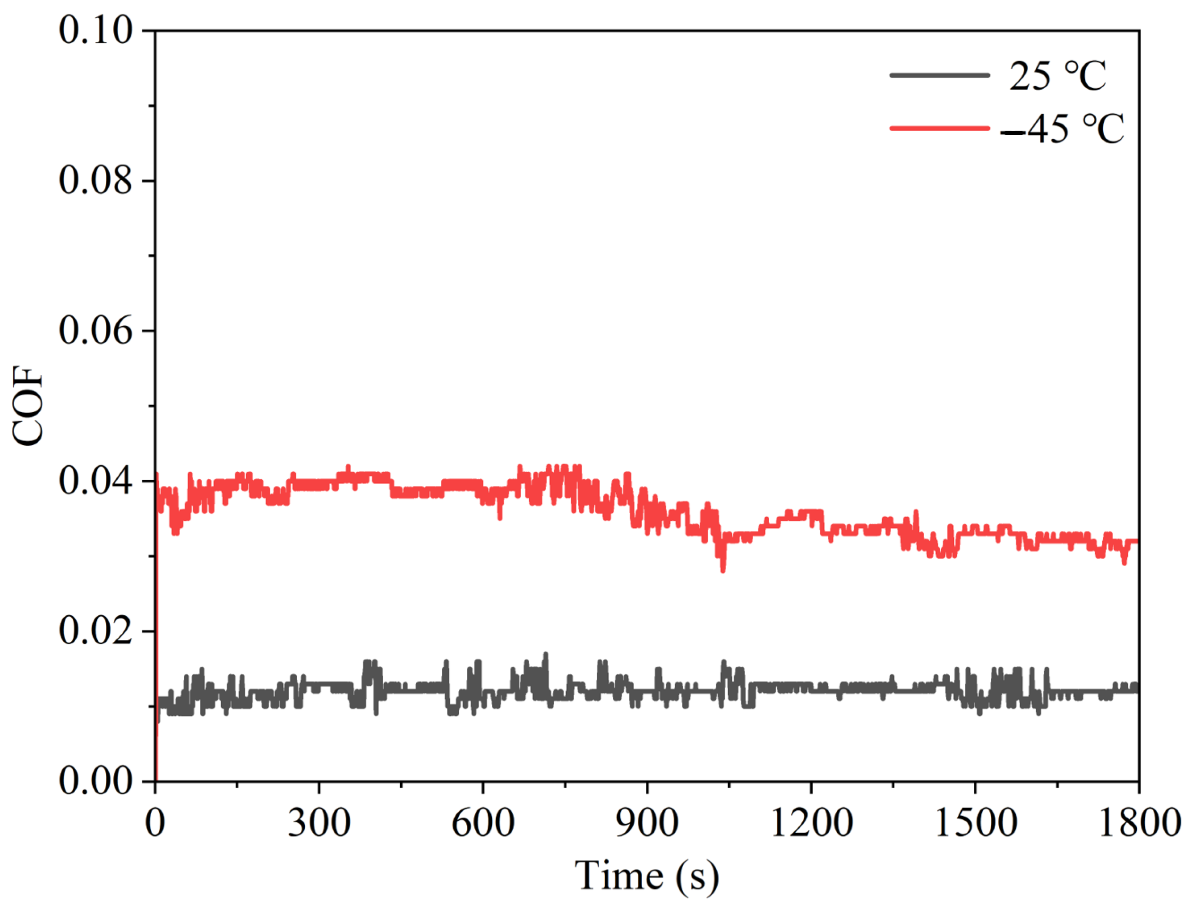
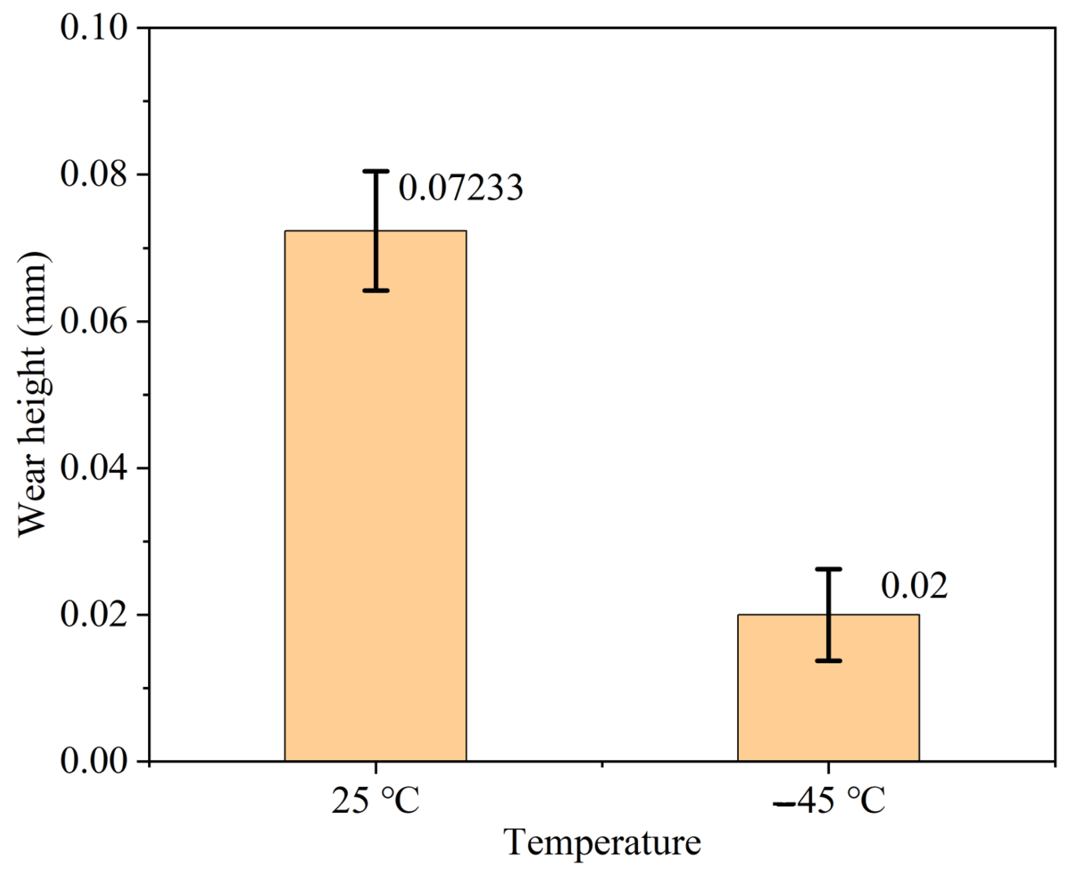
3.5. Tribological Characteristics of PTFE-2

Coefficient of friction: The coefficient of friction of the PTFE-2 material at −45 °C and 25 °C is shown in Figure 15, which was 0.012 at 25 °C and 0.033 at −45 °C. The coefficient of friction at room temperature was 36.4% of that at low temperature. The experiments in this paper matched the results in Ref. [16], where the coefficient of friction of the Al2O3/PTFE material was higher at −50 °C than at 25 °C. The reliability of the experimental results was demonstrated. The obtained friction coefficient was then the friction coefficient of seal-3 under theoretical operating conditions.
Amount of wear: The wear of the PTFE-2 material at a −45 °C and 25 °C temperature is shown in Figure 16, which was 0.072 mm at 25 °C and 0.020 mm at −45 °C. The wear at low temperatures was 27.8% of the wear at room temperature. The pattern also coincided with that in Ref. [16].

4. Conclusions

This paper investigated the tribological behavior and sealing performance of a gasket, PTFE-1 seal and PTFE-2 seal from a seal friction system at high and low temperatures. It analyzed the wear mechanisms and sealing performance and obtained various measurements of the specimens to inform its analyses and conclusions:
  • The smaller the size of the seal ring, the stronger the friction force was affected by temperature. At −45~65 °C, the friction force of the large seal ring seal-3 was 29.3 N (−12.3~19.5%), and the friction force of the small seal ring was 8.3 N (−3.6~95.2%). Therefore, the larger the size of the seal ring, the smaller the influence of the temperature change on its friction force, and the more stable the friction torque.
  • The PTFE-1 seals with a cloud-shaped filler (particle size of 80 μ m) had less leakage than the PTFE-2 seal with a star-shaped filler (particle size of 20 μ m), and its friction torque was lower at −45 °C. Comparing the wear surfaces of the PTFE-1 seal and PTFE-2 seal, it can be seen that PTFE-1 had fatigue wear and PTFE-2 had abrasive and adhesive wear. The wear rate of fatigue wear was lower than that of abrasive and adhesive wear, so the cloud-shaped filler PTFE seal had better wear resistance. In particular, the variation in leakage and friction torque of cloud-filled PTFE seals was less than that of star-shaped PTFE seals when the temperature was reduced from 25 °C to −45 °C. In this comparative study, cloud-filled PTFE had better low-temperature stability than star-filled PTFE, which is a great guidance for any subsequent PTFE material improvement.
This manuscript included the analysis of the gasket, PTFE-2 seal and PTFE-1 seal due to the detailed nature of the investigation but future work would benefit from the testing of additional specimens to increase the statistical power of the study. The article proposes the enhancement of the tribological properties of the seal material by the filler shape, which can be used for other sizes and forms of seals.

Author Contributions

Methodology, J.Z.; formal analysis, L.H.; investigation, X.Z.; writing—original draft, D.L.; project administration, S.L. All authors have read and agreed to the published version of the manuscript.

Funding

This research received no external funding.

Institutional Review Board Statement

Not applicable.

Informed Consent Statement

Not applicable.

Data Availability Statement

Not applicable.

Acknowledgments

The sealing rings used in the test were provided by Aerospace Research Institute of Materials and Processing Technology.

Conflicts of Interest

The authors declare no conflict of interest.

Abbreviations

The following abbreviations are used in this manuscript:
PTFEPolytetrafluoroethylene
EDSEnergy dispersive spectroscopy
DSCDifferential scanning calorimetry
TGAThermal gravimetric analyzer

References

  1. Amenta, F.; Bolelli, G.; De Lorenzis, S.; Bertarini, A.; Lusvarghi, L. Tribological Behavior of Reinforced PTFE Composites and Un-Reinforced Polyketone-Based Materials against Coated Steel. Lubricants 2021, 10, 5. [Google Scholar] [CrossRef]
  2. Tan, B.; Stephens, L.S. Modeling of Rigidly Mounted PTFE Face Seals Subject to Small Strain Harmonic Vibrations. Tribol. Lett. 2022, 70, 110. [Google Scholar] [CrossRef]
  3. Zhang, B.; Yu, M.; Yang, H. Leakage analysis and ground tests of the O-type rubber ring seal applied in lunar sample return devices. Proc. Inst. Mech. Eng. Part J. Aerosp. Eng. 2014, 229, 479–491. [Google Scholar] [CrossRef]
  4. Guo, F. A Mixed Lubrication Theoretical Model and Experimental Verification of Rotary Lip Seals. J. Mech. Eng. 2014, 50, 137. [Google Scholar] [CrossRef]
  5. Ma, K.; Guan, K.; Cai, R. Compression recovery performance of spring energized C-rings. Proc. Inst. Mech. Eng. Part J. Process. Mech. Eng. 2014, 230, 18–25. [Google Scholar] [CrossRef]
  6. Shabbir, S.; Garvey, S.D.; Dakka, S.M.; Rothwell, B.C.; Su, R.; Leach, R.; Weston, N. Analysis of the tribological interaction of a polytetrafluoroethylene-lined radial lip oil seal, shaft and lubricant sample. Proc. Inst. Mech. Eng. Part J. Eng. Tribol. 2021, 236, 123–143. [Google Scholar] [CrossRef]
  7. Gong, R.; Wan, X.; Zhang, X. Tribological properties and failure analysis of PTFE composites used for seals in the transmission unit. J. Wuhan Univ. Technol. Mater. Sci. Ed. 2013, 28, 26–30. [Google Scholar] [CrossRef]
  8. Tan, G.; Huang, X.; Gao, J.; Zhang, Y.; Tian, Y. Analysis of In-situ Testing Technology and Equipment for the Large Deformation Frictional Contact with Compliant Elastomer. Tribology 2022, 42, 187–201. [Google Scholar] [CrossRef]
  9. Peng, X.; Yao, N.; Heng, Z.; Chen, Y.; Zou, H.; Zhou, S.; Liang, M. Controllable design of polytetrafluoroethylene chemical component using the “harmful” irradiation heat. Polym. Adv. Technol. 2022, 33, 1956–1966. [Google Scholar] [CrossRef]
  10. Wang, J.; Huang, X.; Wang, W.; Han, H.; Duan, H.; Yu, S.; Zhu, M. Effects of PTFE coating modification on tribological properties of PTFE/aramid self-lubricating fabric composite. Mater. Res. Express 2022, 9, 5. [Google Scholar] [CrossRef]
  11. Lin, Z.; Zhang, K.; Ye, J.; Li, X.; Zhao, X.; Qu, T.; Liu, Q.; Gao, B. The effects of filler type on the friction and wear performance of PEEK and PTFE composites under hybrid wear conditions. Wear 2022, 490–491, 204178. [Google Scholar] [CrossRef]
  12. Struchkova, T.S.; Vasilev, A.P.; Okhlopkova, A.A.; Danilova, S.N.; Alekseev, A.G. Mechanical and Tribological Properties of Polytetrafluoroethylene Composites Modified by Carbon Fibers and Zeolite. Lubricants 2021, 10, 4. [Google Scholar] [CrossRef]
  13. Cheng, X.; Xue, Y.; Xie, C. Tribological investigation of PTFE composite filled with lead and rare earths-modified glass fiber. Mater. Lett. 2003, 57, 2553–2557. [Google Scholar] [CrossRef]
  14. Unal, H.; Kurtulus, E.; Mimaroglu, A.; Aydin, M. Tribological Performance of PTFE Bronze Filled Composites under Wide Range of Application Conditions. J. Reinf. Plast. Compos. 2009, 29, 2184–2191. [Google Scholar] [CrossRef]
  15. Unal, H.; Yetgin, S.H.; Mimaroglu, A.; Sumer, M. The Effect of Test Parameters on Friction and Wear Performance of PTFE and PTFE Composites. J. Reinf. Plast. Compos. 2009, 29, 1978–1986. [Google Scholar] [CrossRef]
  16. Qi, H.; Hu, C.; Li, J.; Huang, C.; Zhou, Y.; Cui, J.; Yu, J.; Zhang, G. Tribological Performance of PTFE and Its Composite in Wide Temperature Range. Tribology 2022, 42, 65–73. [Google Scholar] [CrossRef]
  17. Gong, R.; Liu, M.; Zhang, H.; Xu, Y. Experimental investigation on frictional behavior and sealing performance of different composites for seal application. Wear 2015, 342–343, 334–339. [Google Scholar] [CrossRef]
  18. Li, K.; Jia, X.; Guo, F. A model for breakaway distance and maximum static friction to study the static frictional behavior of the secondary seal in non-contacting mechanical seals. Tribol. Int. 2019, 135, 219–229. [Google Scholar] [CrossRef]
  19. Huang, T.C.; Tsai, J.W.; Liao, K.C. Wear and leakage assessments of canted coil Spring–Energized polytetrafluoroethylene seals under Ultra-High cycle operations. Eng. Fail. Anal. 2022, 135, 106110. [Google Scholar] [CrossRef]
  20. Gao, L.; Ji, X.; Zhang, K.; Li, Z.-W.; Zhang, Y.-K. Influence of mixing process on the mechanical and tribological properties of PTFE composites. Plast. Rubber Compos. 2020, 50, 146–152. [Google Scholar] [CrossRef]
  21. Mazur, K.; Gadek-Moszczak, A.; Liber-Knec, A.; Kuciel, S. Mechanical Behavior and Morphological Study of Polytetrafluoroethylene (PTFE) Composites under Static and Cyclic Loading Condition. Materials 2021, 14, 1712. [Google Scholar] [CrossRef] [PubMed]
  22. Sonawane, A.; Deshpande, A.; Chinchanikar, S.; Munde, Y. Dry sliding wear characteristics of carbon filled polytetrafluoroethylene (PTFE) composite against Aluminium 6061 alloy. Mater. Today Proc. 2021, 44, 3888–3893. [Google Scholar] [CrossRef]
  23. Toth, L.F.; Szebenyi, G.; Sukumaran, J.; De Baets, P. Tribological characterization of nanoparticle filled PTFE: Wear-induced crystallinity increase and filler accumulation. Express Polym. Lett. 2021, 15, 972–986. [Google Scholar] [CrossRef]
  24. AuXie, T.; Shi, Y. Effects of LaF3/CeF3 on the friction transfer of PTFE-based composites. Tribol. Int. 2021, 161, 107069. [Google Scholar] [CrossRef]
  25. Li, X.; Wu, S.; Jia, X.; Ling, Y.; Dai, Y.; Zhang, C.; Luo, J. Tribological and compressive creep properties of polytetrafluoroethylene/nickeltitanium shape memory alloy composites. Polym. Compos. 2022, 43, 3003–3014. [Google Scholar] [CrossRef]
  26. Zhang, K.; Ji, X.; Mi, Y.; Gao, L.; Wang, T. Effects of carbon fibers with different particle sizes on the physical properties of MoS2-filled PTFE composites. Philos. Mag. Lett. 2021, 101, 277–286. [Google Scholar] [CrossRef]
  27. Visconte, C.; Conte, M.; Mattone, M.C. Analysis of the leakage path in an air-lubricated seal. Tribol. Int. 2009, 42, 844–848. [Google Scholar] [CrossRef]
Figure 1. Layout of the wide-temperature-range friction system.
Machines 11 00221 g001
Figure 2. Seal test apparatus. (a) Layout of seal test apparatus. (b) Two types of gaskets in contact and friction with the seal ring.
Machines 11 00221 g002
Figure 3. Sealing ring. (a) Picture of spring-energized seal. (b) Principle of spring-energized seal.
Machines 11 00221 g003
Figure 4. EDS results for seal shell material (PTFE). (a) Pure PTFE surface’s micromorphology; (b) PTFE-1 surface’s micromorphology; (c) PTFE-2 surface’s micromorphology; (d) surface elemental distribution of pure PTFE; (e) surface elemental distribution of PTFE-1; (f) surface elemental distribution of PTFE-2; (g) pure PTFE surface’s C elemental distribution; (h) PTFE-1 surface’s C elemental distribution; (i) PTFE-2 surface’s C element distribution; (j) pure PTFE surface’s F element distribution; (k) PTFE-1 surface’s F element distribution; (l) PTFE-2 surface’s F element distribution.
Machines 11 00221 g004
Figure 5. Comparative analysis of the thermal performance results of the three materials. (a) TGA of pure PTFE, PTFE-1 and PTFE-2; (b) DTA of pure PTFE, PTFE-1 and PTFE-2; (c) DSC of pure PTFE, PTFE-1 and PTFE-2.
Machines 11 00221 g005
Figure 6. Curve of friction torque versus time of PTFE-2-seal-3 seal ring.
Machines 11 00221 g006
Figure 7. Friction torque and frictional force of three different sizes of PTFE-2 sealing ring at different temperatures. (a) Friction torque; (b) frictional force.
Machines 11 00221 g007
Figure 8. Friction torque of PTFE-1 and PTFE-2 sealing rings at different temperatures.
Machines 11 00221 g008
Figure 9. Results of leakage rate at different temperatures and sizes. (a) Leakage rate of seal-1-PTFE-2 varies with time at different temperatures. (b) Leakage rate of seal-2-PTFE-2 varies with time at different temperatures. (c) Leakage rate of seal-3-PTFE-2 varies with time at different temperatures.
Machines 11 00221 g009
Figure 10. Leakage rate of PTFE-1 and PTFE-2 sealing rings at different temperatures.
Machines 11 00221 g010
Figure 11. Wear marks on the sealing surface of the gasket and sealing ring.
Machines 11 00221 g011
Figure 12. Surface topography of gasket. (a) Surface topography before wear test, magnification 83. (b) Surface topography before wear test, magnification 1000. (c) Surface topography after wear test, magnification 83. (d) Surface topography after wear test, magnification 1000. (e) Wear debris of PTFE-1 on the gasket, magnification 1000. (f) Wear debris of PTFE-2 on the gasket, magnification 1000.
Machines 11 00221 g012
Figure 13. Surface topography of PTFE-2 seal ring. (a) Surface topography before wear test, magnification 83. (b) Surface topography before wear test, magnification 1000. (c) Surface topography after wear test, magnification 83. (d) Surface topography after wear test, magnification 1000. (e) Wear debris of PTFE-2 on the gasket, magnification 1000. (f) Wear debris of PTFE-2 on the gasket, magnification 1000.
Machines 11 00221 g013
Figure 14. Surface topography of PTFE-1 seal ring. (a) Surface topography before wear test, magnification 83. (b) Surface topography before wear test, magnification 1000. (c) Surface topography after wear test, magnification 83. (d) Surface topography after wear test, magnification 1000. (e) Wear debris of PTFE-1 on the gasket, magnification 1000. (f) Wear debris of PTFE-1 on the gasket, magnification 1000.
Machines 11 00221 g014
Figure 15. The coefficient of friction of PTFE-2.
Machines 11 00221 g015
Figure 16. The wear of the PTFE-2 material.
Machines 11 00221 g016
Table 1. Groove sizes of three spring-energized seals.
SealOutside Diameter/mmInside Diameter/mmDepth/mm
192.07582.552.3
2104.77595.252.3
3228.6219.0752.3
Table 2. Material properties of spring-energized seals.
PTFE-1PTFE-2316 Stainless Steel
Shore hardness D/HD71.268.5-
Elastic modulus/MPa480442232,200
Yield strength/MPa20181500
Disclaimer/Publisher’s Note: The statements, opinions and data contained in all publications are solely those of the individual author(s) and contributor(s) and not of MDPI and/or the editor(s). MDPI and/or the editor(s) disclaim responsibility for any injury to people or property resulting from any ideas, methods, instructions or products referred to in the content.

