
Research on Multi-Body Collision Dynamics of Ball Cage Flexible Drill Pipe Considering Borehole Curvature

 ,
,
Abstract
:1. Introduction
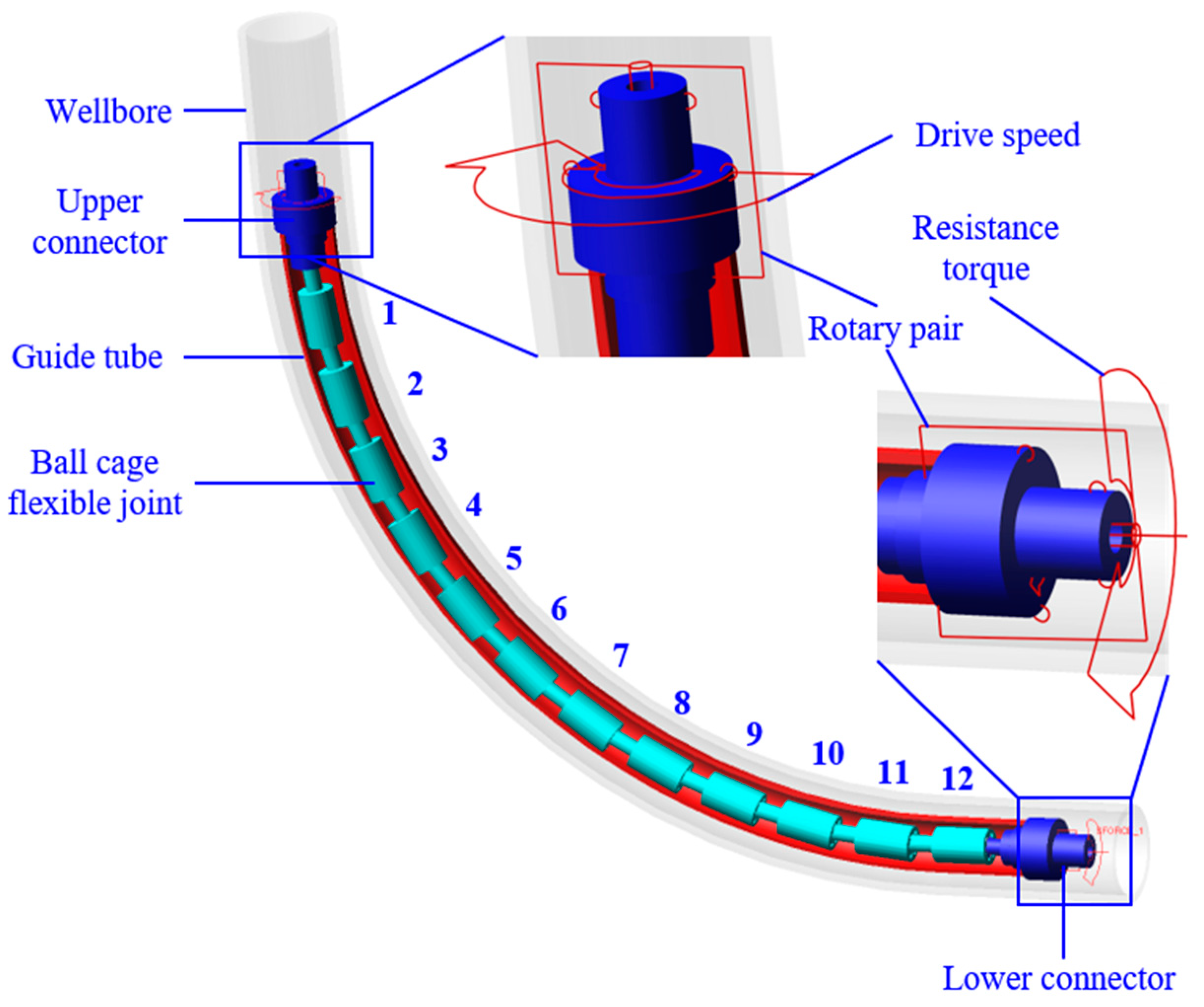
2. Multi-Body Dynamics Model of Flexible Drill Pipe
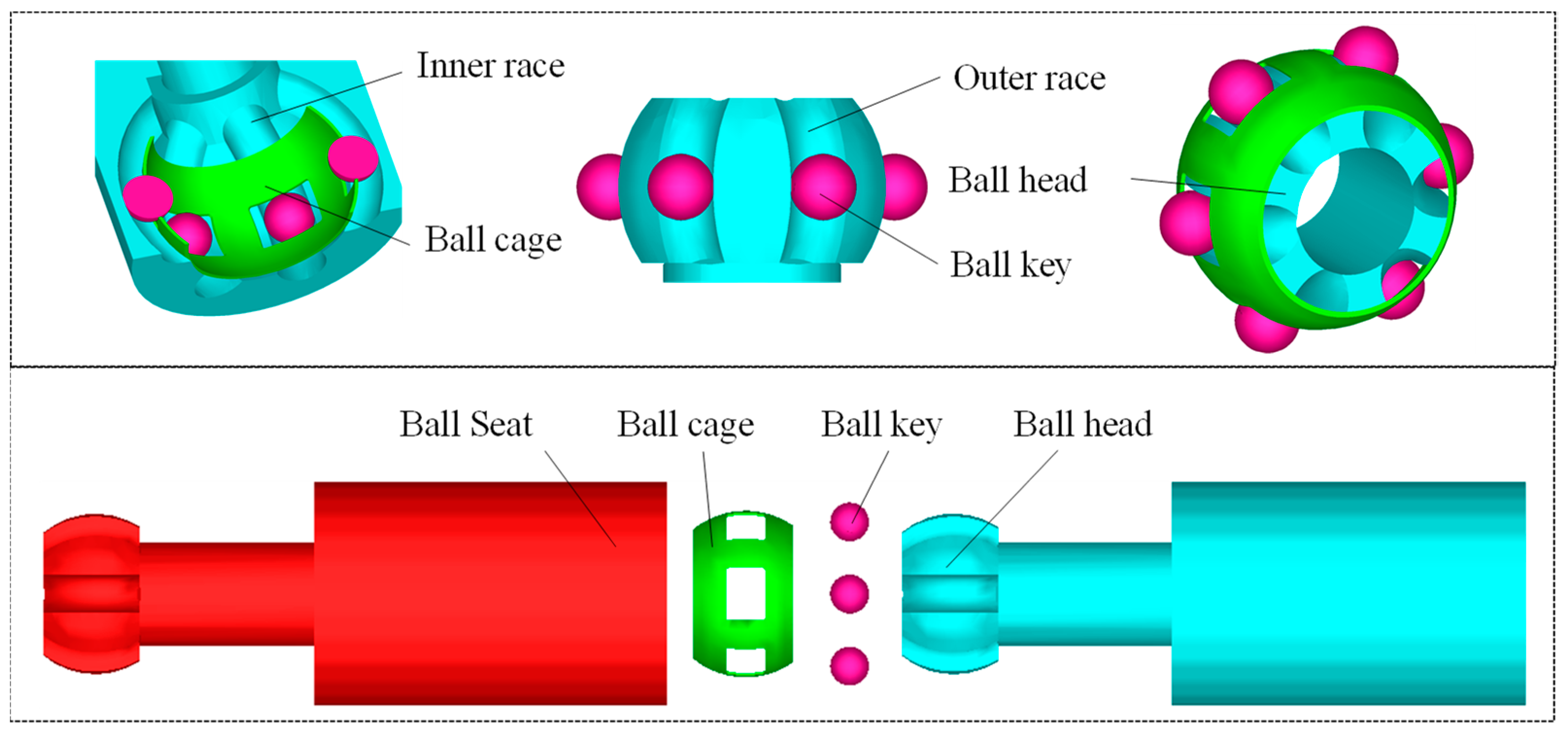
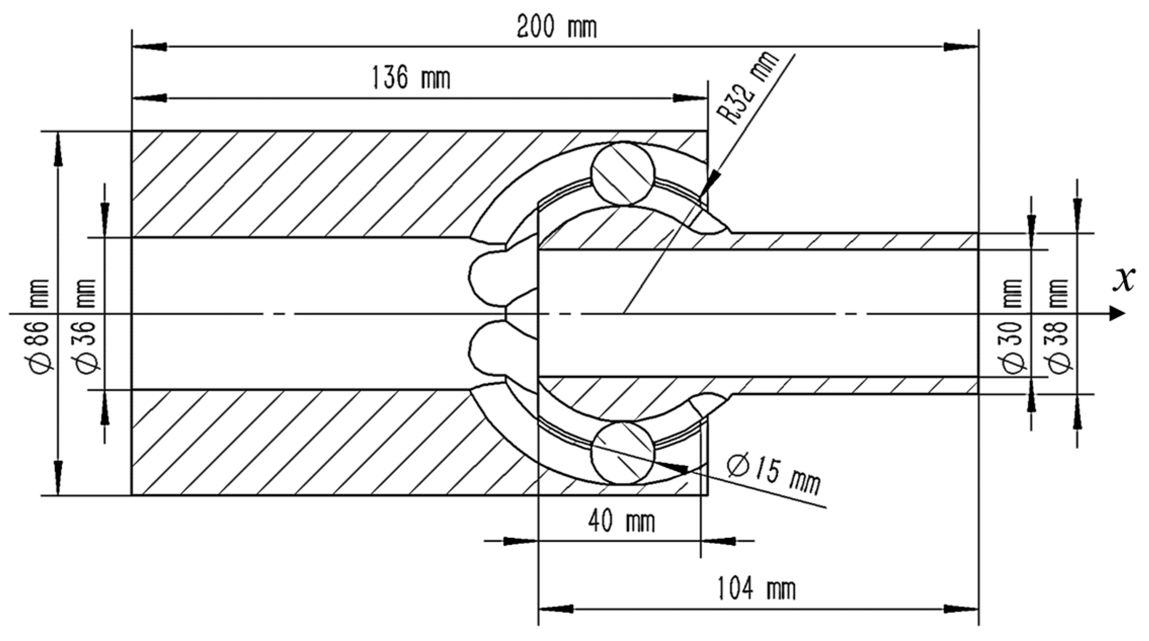
2.1. Geometry Equation of Ball Cage Universal Joint
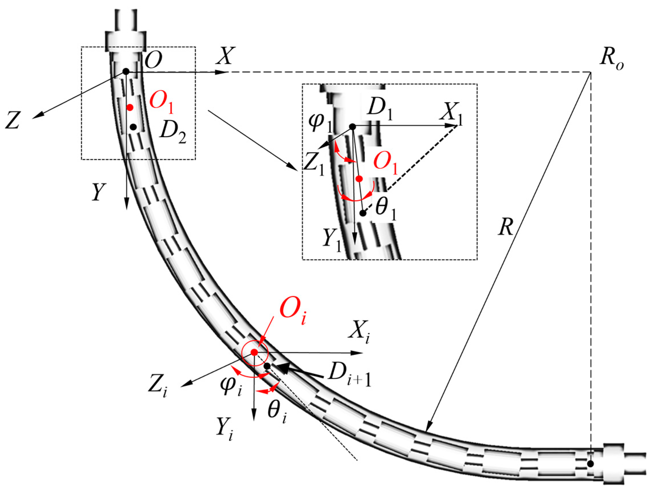
2.2. Kinematic Equation of Flexible Drill Pipe
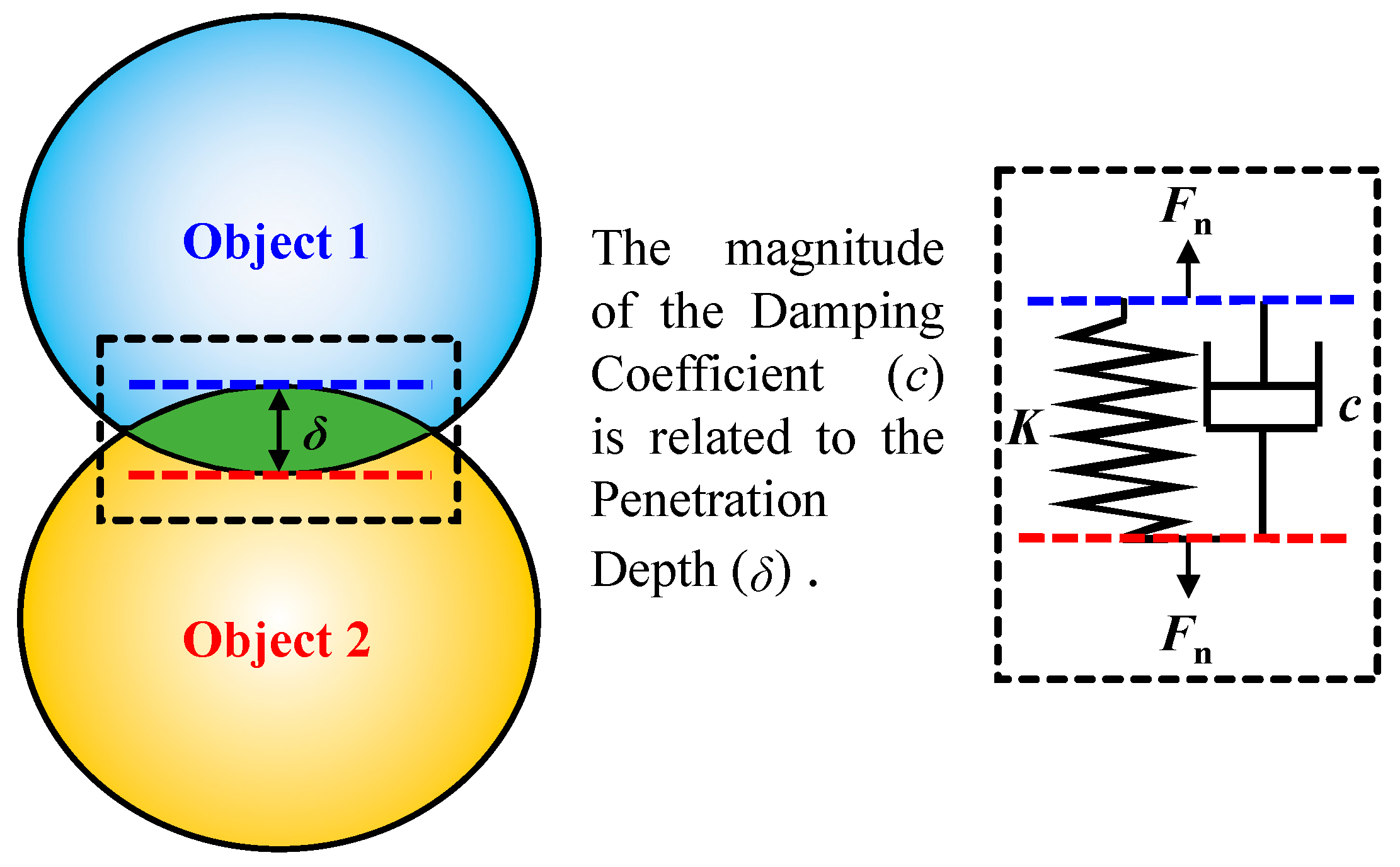
2.3. Dynamics Model of Contact
3. Analysis of Flexible Drill Pipe Collision Contact
3.1. Motion Trail of Flexible Joint
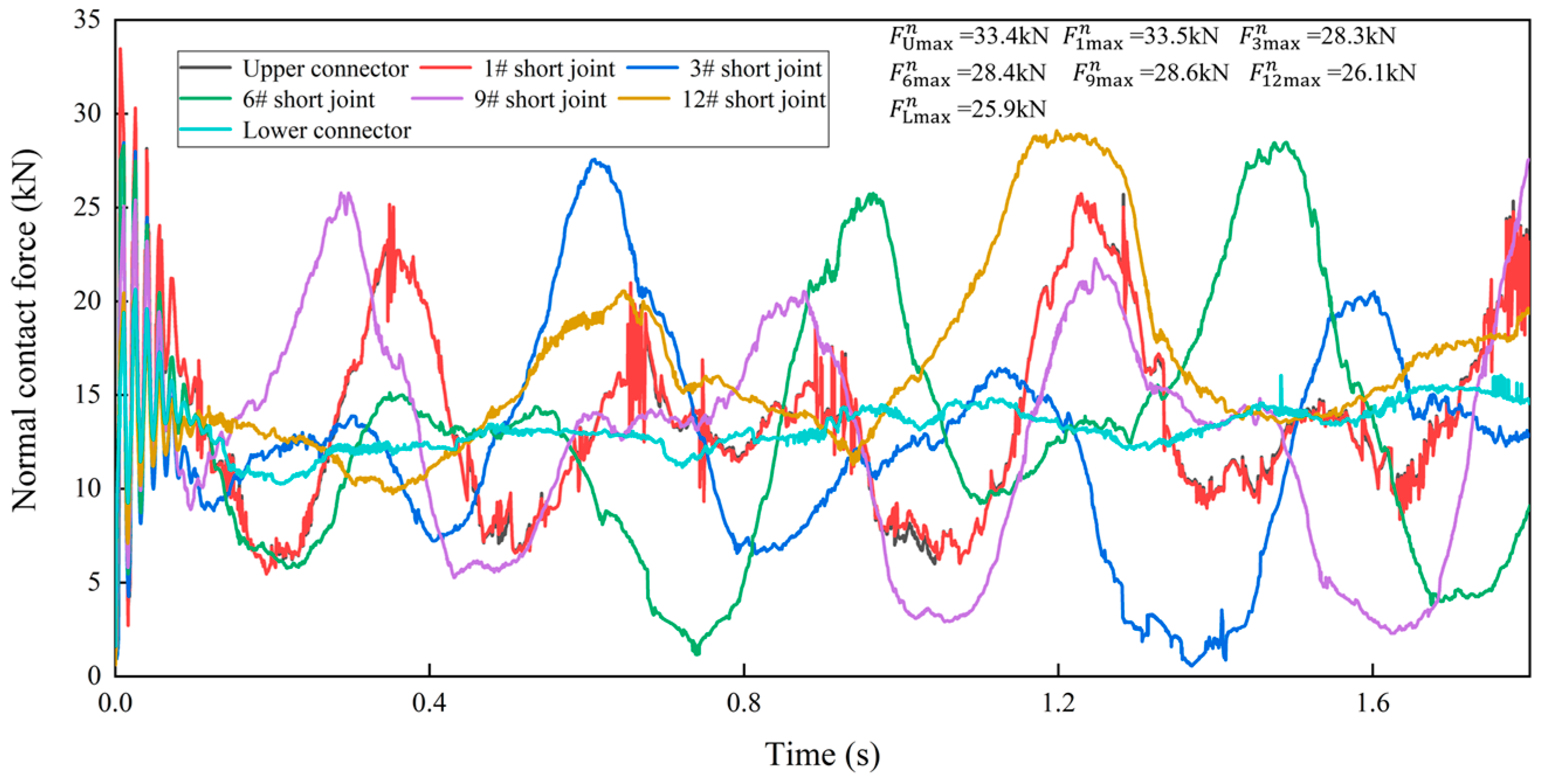
3.2. Analysis of the Contact between the Flexible Joint and the Guide Tube
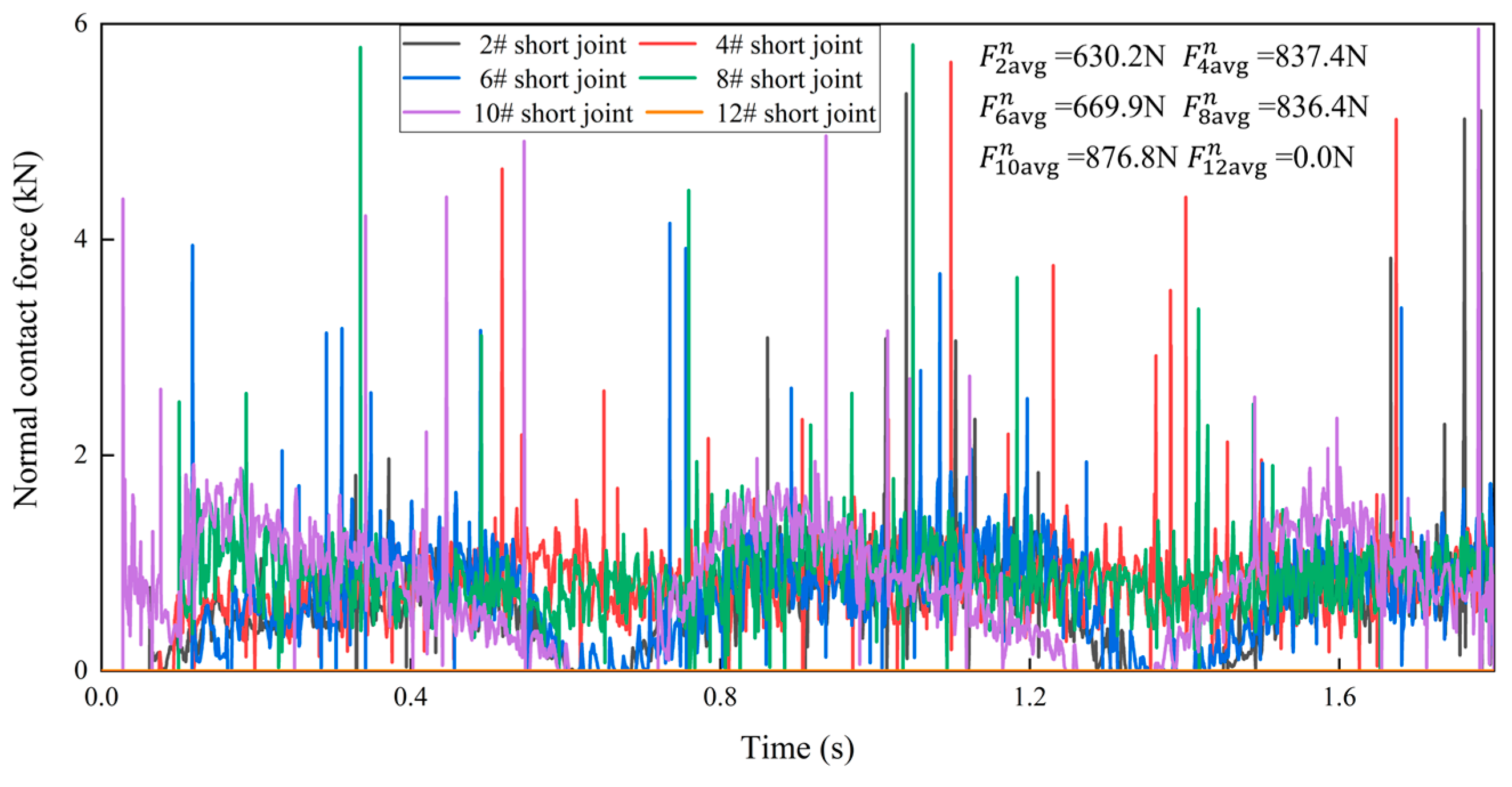
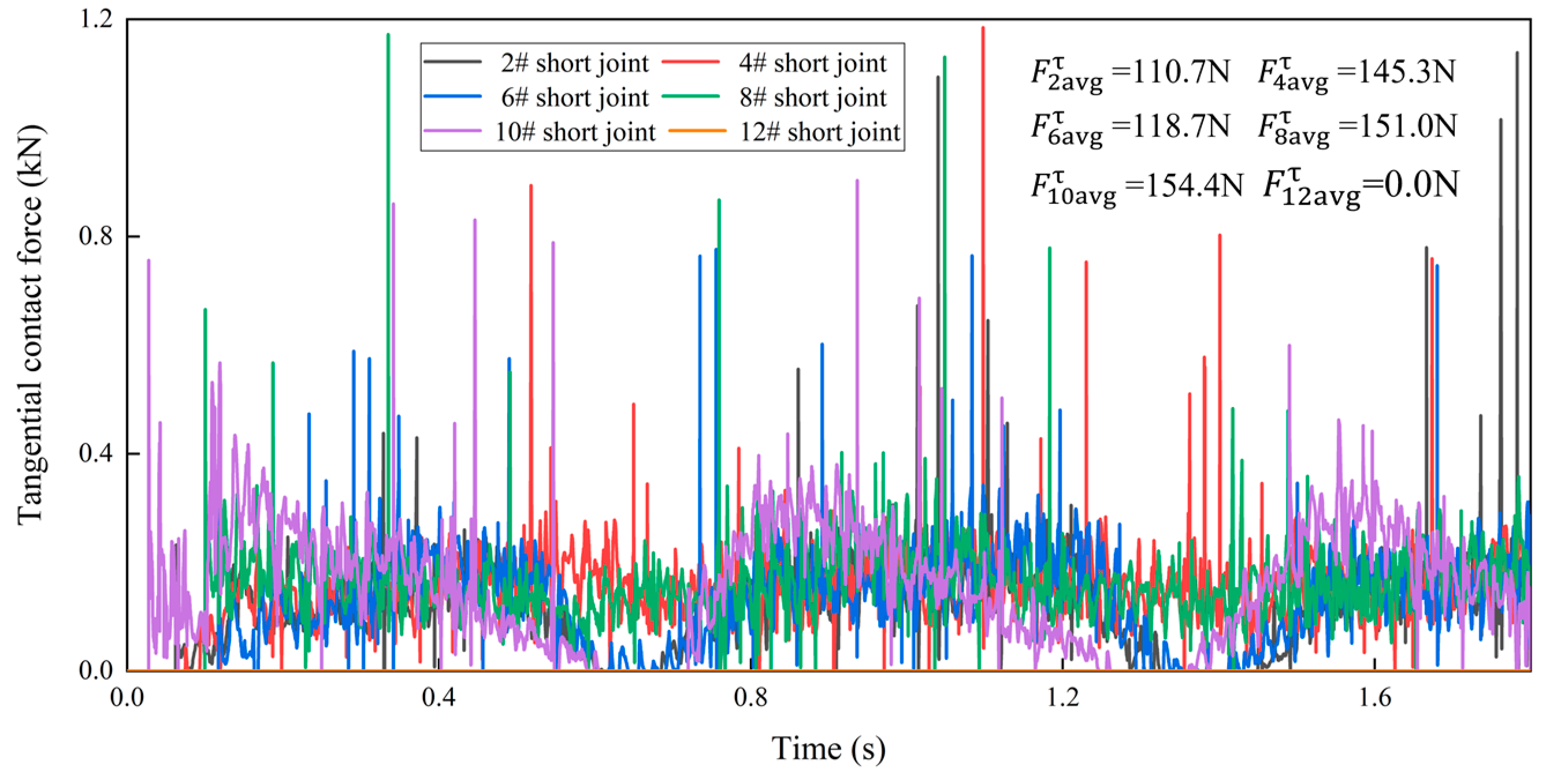
3.3. Analysis of Flexible Drill Pipe Internal Contact
4. Parameter Influence
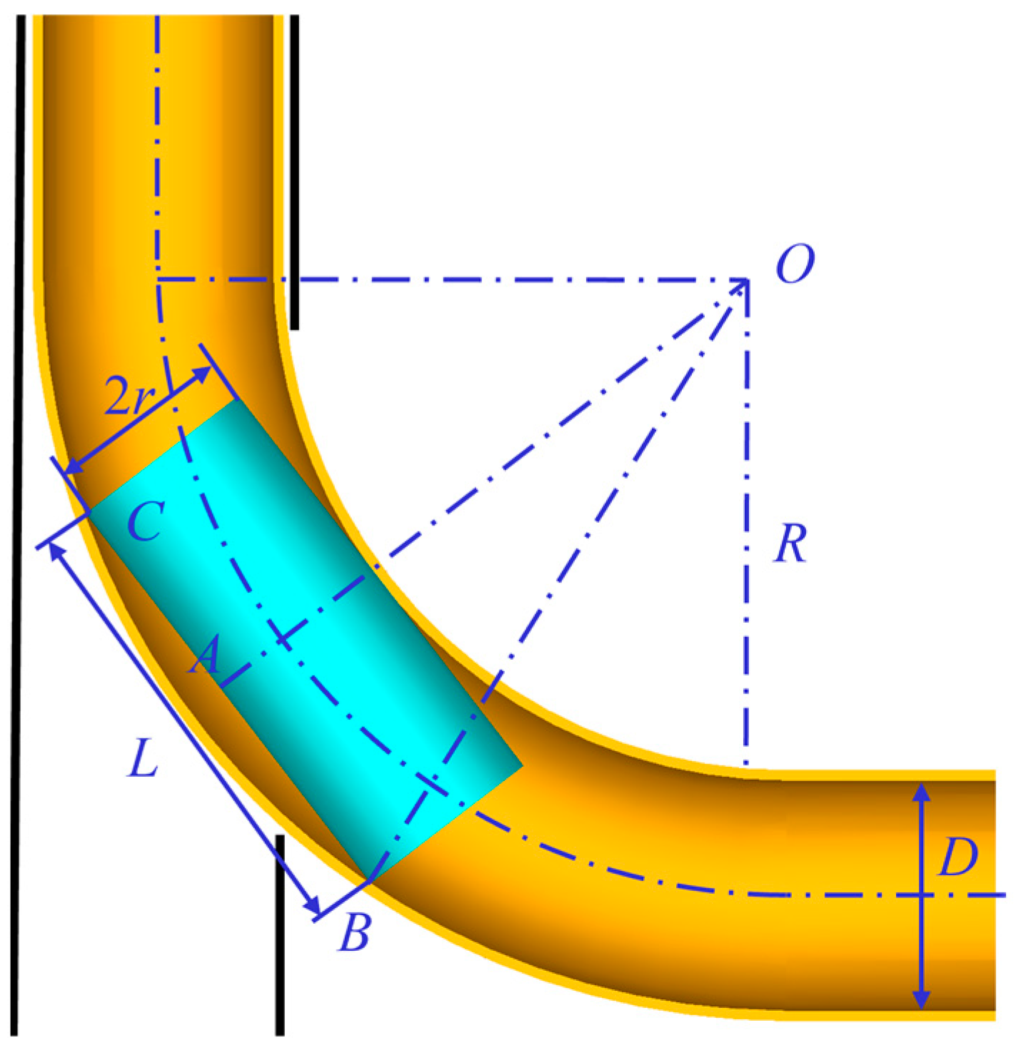
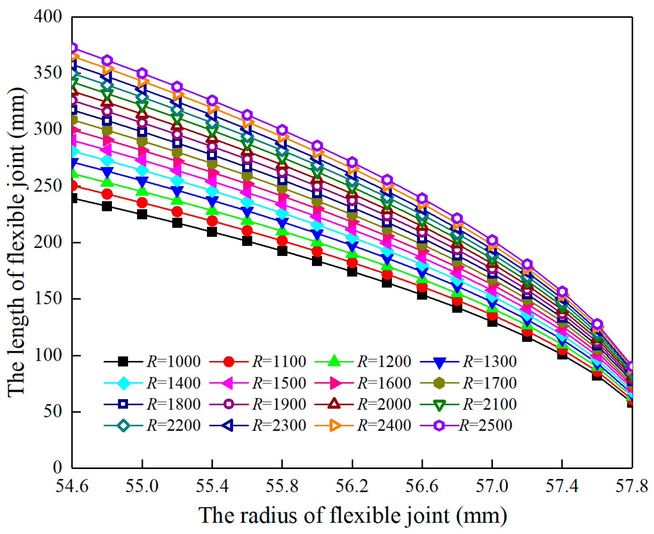
4.1. Influence of Borehole Curvature on the Length of Flexible Joint
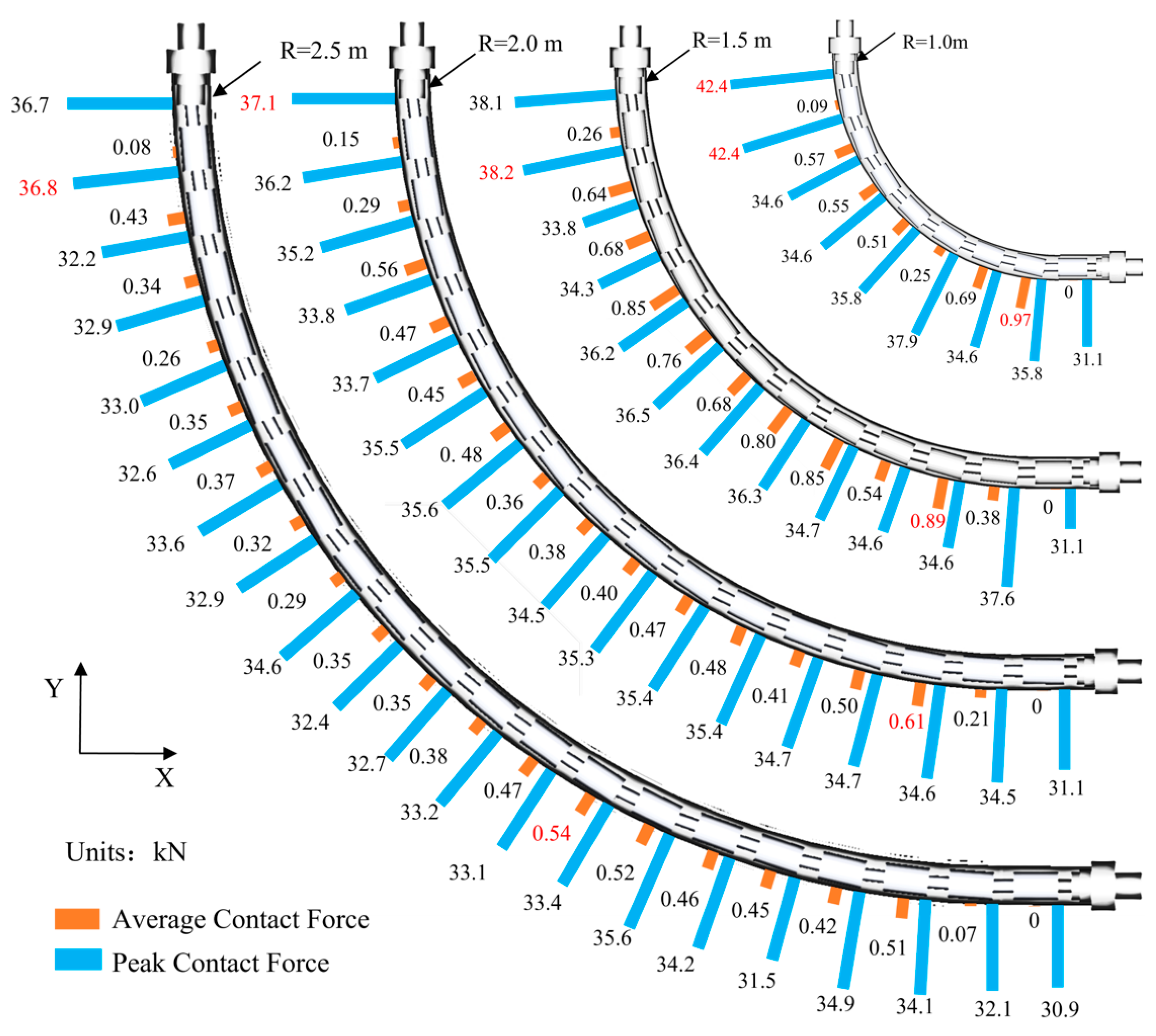
4.2. Influence of Borehole Curvature on Collision Contact Force
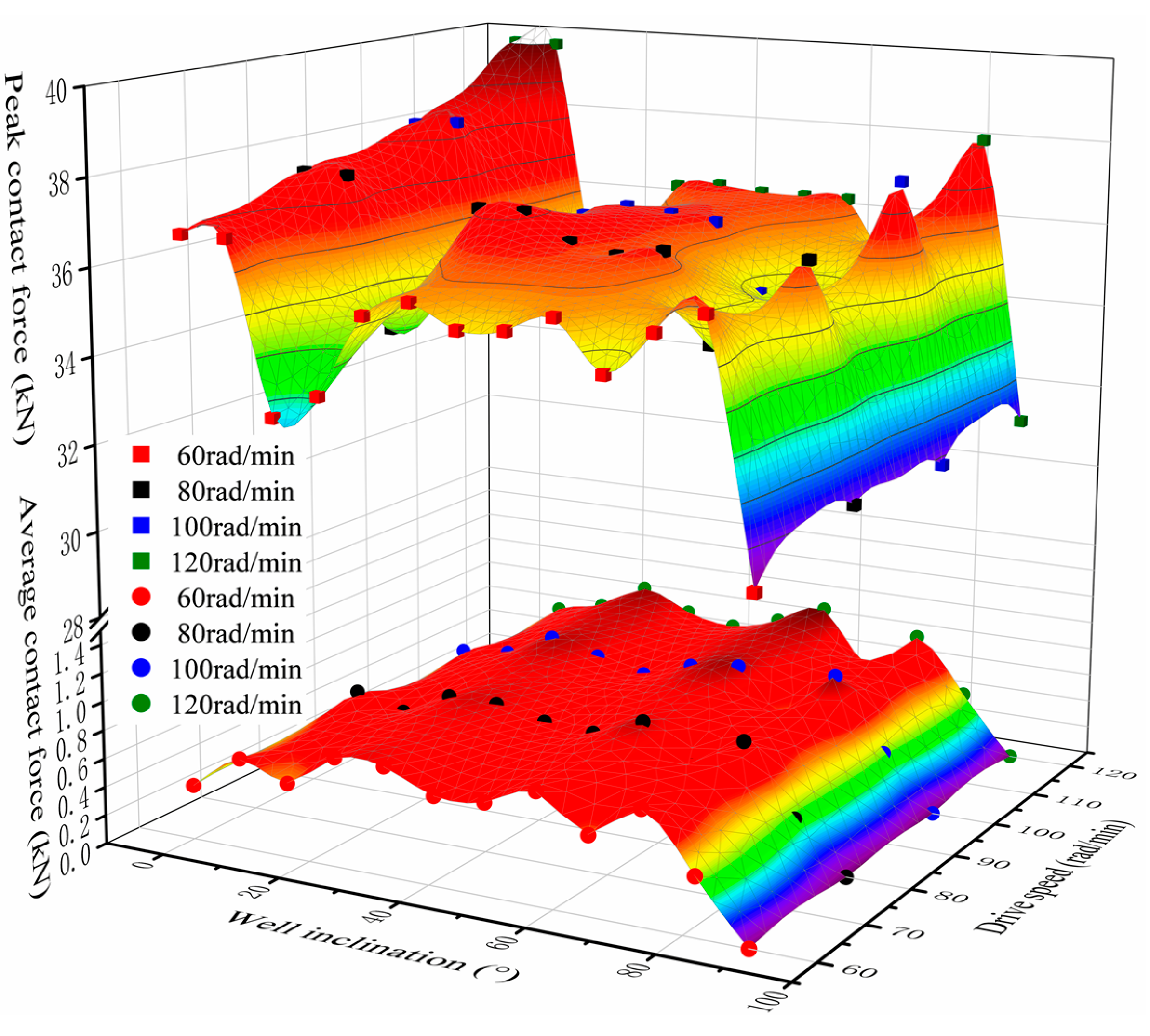
4.3. Influence of Drive Speed
5. Conclusions
- (1)
- The deformation of the ball-cage flexible drill pipe shows a “folded” shape compared to the initial form, and the nearer to the middle, the greater the degree of “fold”.
- (2)
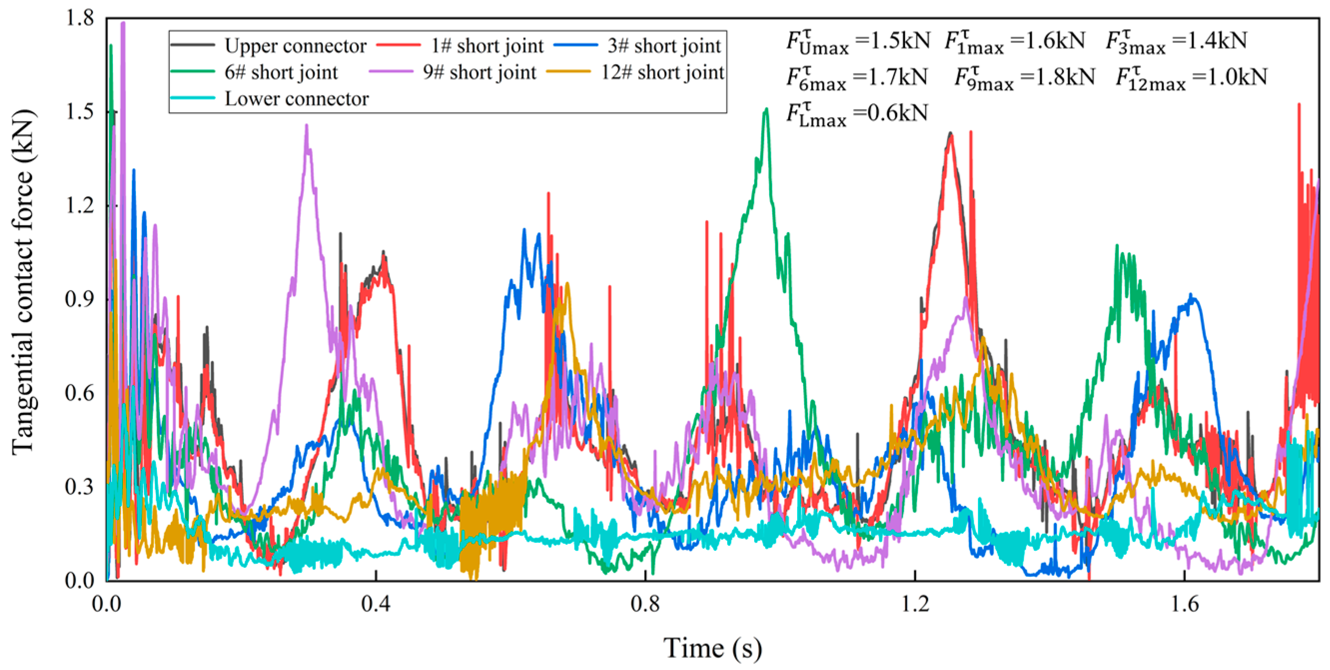
- The contact force between the flexible drill pipe and the guide tube is randomly distributed, and the change in collision contact force is closely related to the borehole curvature radius. When the borehole curvature radius decreases, the contact force increases significantly, and the drilling load loss is very high. The contact force of different flexible joints is in a fluctuation state, and the normal contact force of flexible joints is much larger than the tangential contact force.
- (3)
- The geometric relationship among borehole curvature, flexible joint length, and radius is derived, which provides criteria for the flexible joint size design to ensure the reliability of a flexible drill pipe in large curvature boreholes.
- (4)
- The driving speed is positively related to the average contact force between the flexible drill pipe and the guide tube and the peak contact force between the flexible drill pipe and the ball key.
Author Contributions
Funding
Data Availability Statement
Conflicts of Interest
References
- Cao, X.; Zhang, C.; Zhang, C. A Kind of Ultra-Short Radius Radial Horizontal Drilling and Completion Tool and Drilling and Completion Technology. China Patent CN100567695C, 9 December 2009. [Google Scholar]
- Moustafa, E.B.; Elsheikh, A. Predicting Characteristics of Dissimilar Laser Welded Polymeric Joints Using a Multi-Layer Perceptrons Model Coupled with Archimedes Optimizer. Polymers 2023, 15, 233. [Google Scholar] [CrossRef]
- Khoshaim, A.B.; Moustafa, E.B.; Bafakeeh, O.T.; Elsheikh, A.H. An Optimized Multilayer Perceptrons Model Using GreyWolf Optimizer to Predict Mechanical and Microstructural Properties of Friction Stir Processed Aluminum Alloy Reinforced by Nanoparticles. Coatings 2021, 11, 1476. [Google Scholar] [CrossRef]
- Elsheikh, A. Bistable Morphing Composites for Energy-Harvesting Applications. Polymers 2022, 14, 1893. [Google Scholar] [CrossRef]
- Elsheikh, A.H.; El-Said, E.M.; Abd Elaziz, M.; Fujii, M.; El-Tahan, H.R. Water distillation tower: Experimental investigation, economic assessment, and performance prediction using optimized machine-learning model. J. Clean. Prod. 2023, 388, 135896. [Google Scholar] [CrossRef]
- Luo, M.; Xu, T.; Jiang, J.; Chi, X.; Wang, J.; Xue, S. Two-layer Contact Nonlinear Mechanical Analysis of Flexible Drilling Tool in The Wellbore. Comput. Model. Eng. Sci. 2020, 123, 75–100. [Google Scholar] [CrossRef]
- Zhu, X.; Xu, Y.; Zhou, W.; Ye, G.; Zhou, B. Research on Parameter Design Method and Motion Characteristics of a Ball Cage Flexible Joint. Energies 2022, 15, 7591. [Google Scholar] [CrossRef]
- Bai, Z.F. Research on Dynamic Characteristic of Mechanism with Joint Clearance; Harbin Institute of Technology: Harbin, China, 2011. [Google Scholar]
- Hunt, K.H.; Crossley, F.R. Coefficient of restitution interpreted as damping in vibroimpact. J. Appl. Mech. 1975, 42, 440–445. [Google Scholar] [CrossRef]
- Lankarani, H.M.; Nikravesh, P.E. A contact force model with hysteresis damping for impact analysis of multibody systems. J. Mech. Des. 1990, 112, 369–376. [Google Scholar] [CrossRef]
- Luka, S.; Janko, S.; Miha, B. A validated model for a pin-slot clearance joint. Nonlinear Dyn. 2017, 88, 131–143. [Google Scholar] [CrossRef]
- Alexander, G.; Bernd, S. Modeling planar slider-crank mechanisms with clearance joints in recurdyn. Multibody Syst. Dyn. 2014, 31, 127–145. [Google Scholar] [CrossRef]
- Bai, Z.F.; Zhao, Y. Dynamics modeling and quantification analysis of multibody systems including revolute clearance joints. Precis. Eng. 2012, 36, 554–567. [Google Scholar] [CrossRef]
- Wang, X.P.; Liu, G.; Ma, S.J. Dynamic analysis of planar mechanical systems with clearance joints using a new nonlinear contact force model. J. Mech. Sci. Technol. 2016, 30, 1537–1545. [Google Scholar] [CrossRef]
- Manzoli, O.L.; Tosati, M.; Rodrigues, E.A.; Bitencourt, L.A. Computational modeling of 2D frictional contact problems based on the use of coupling finite elements and combined contact/friction damage constitutive model. Finite Elem. Anal. Des. 2022, 199, 103658. [Google Scholar] [CrossRef]
- Yue, J.; Liu, G.-R.; Li, M.; Niu, R. A cell-based smoothed finite element method for multi-body contact analysis using linear complementarity formulation. Int. J. Solids Struct. 2018, 141, 110–126. [Google Scholar] [CrossRef]
- Kimata, K.; Nagatani, H.; Imoto, M.; Kohara, T. Numerical analyses and experiments on the characteristics of ball-type constant-velocity joints. JSME Int. J. 2004, 47, 746–754. [Google Scholar] [CrossRef] [Green Version]
- Wang, G.; Liu, H.; Deng, P.; Yin, K.; Zhang, G. Dynamic analysis of 4-SPS/CU parallel mechanism considering three-dimensional wear of spherical joint with clearance. J. Tribol. 2017, 139, 021608. [Google Scholar] [CrossRef]
- Marques, F.; Flores, P.; Claro, J.C.P.; Lankarani, H.M. Modeling and analysis of friction including rolling effects in multibody dynamics: A review. Multibody Syst. Dyn. 2019, 45, 223–244. [Google Scholar] [CrossRef]
- Chen, X.; Hu, Q.; Xu, Z.; Zhu, C. Numerical modeling and dynamic characteristics study of coupling vibration of multistage face gearsplanetary transmission. Mech. Sci. 2019, 10, 475–495. [Google Scholar] [CrossRef]
- Onesmus, M.; John, K.; Bernard, I. Numerical study of parametric effects on the dynamic response of planar multi-body systems with differently located frictionless revolute clearance joints. Mech. Mach. Theory 2012, 53, 30–49. [Google Scholar] [CrossRef]
- Luo, M.; Xu, T.; Wang, J.; Li, Q.Z.; Zhang, J.H. Contact nonlinear finite element analysis of controllable universal joint flexible slender in tube. J. China Univ. Pet. (Ed. Nat. Sci.) 2019, 43, 75–81. [Google Scholar] [CrossRef]
- Luo, G.; Zou, L.; Huang, Y.; Gong, M. Study on material removal and surface quality in titanium alloy grinding with alumina hollow-sphere abrasive belt. China Mech. Eng. 2020, 15, 1798–1807. [Google Scholar] [CrossRef]
- Liu, Q.; Tong, K.; Zhu, G.-C.; Tan, Y.; Zhang, J.; Xu, X.; Li, X.; Song, S.-Y. Investigation of fracture causes of the titanium alloy drill pipe in ultra-short radius horizontal well drilling. Eng. Fail. Anal. 2022, 140, 106516. [Google Scholar] [CrossRef]


| Number | Name | External Diameter/mm | Inner Diameter/mm | Length/mm |
|---|---|---|---|---|
| 1 | Wellbore | - | 124 | - |
| 2 | Guide tube | 121 | 116 | 750 |
| 3 | Upper/lower connector | 122 | 30 | 200 |
| 4 | Flexible joint | 86 | 30 | 200 |
| 5 | Ball head | 62 | 30 | 104 |
| 6 | Ball cage | 64 | 62 | 40 |
| 7 | Ball key | 15 | - | - |
| 8 | Ball seat | 86 | 64 | 136 |
| Component | Upper Connector | Ball Cage | Flexible Joint |
|---|---|---|---|
| Ball cage | Collision friction contact | -- | |
| Ball head | Collision friction contact | ||
| Ball key | Collision friction contact | Collision friction contact | |
| Lower connector | Collision friction contact | ||
| Guide tube | Collision friction contact |
| Position and Relative Displacement of Flexible Drill Pipe | Shape of Flexible Joint | |||
|---|---|---|---|---|
| 0° |  | 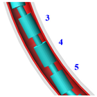 | ||
| Joint number with maximum deformation | Adjacent included angle | Range of motion | ||
| 4# | 173.2° | 23.6 mm | ||
| 90° |  | 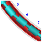 | ||
| Joint number with maximum deformation | Adjacent included angle | Range of motion | ||
| 6# | 173.6° | 24.5 mm | ||
| 180° |  |  | ||
| Joint number with maximum deformation | Adjacent included angle | Range of motion | ||
| 5# | 172.8° | 25.0 mm | ||
| 270° | 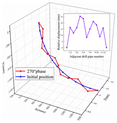 | 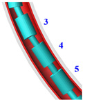 | ||
| Joint number with maximum deformation | Adjacent included angle | Range of motion | ||
| 4# | 25.3 mm | 176.0° | ||
Disclaimer/Publisher’s Note: The statements, opinions and data contained in all publications are solely those of the individual author(s) and contributor(s) and not of MDPI and/or the editor(s). MDPI and/or the editor(s) disclaim responsibility for any injury to people or property resulting from any ideas, methods, instructions or products referred to in the content. |
© 2023 by the authors. Licensee MDPI, Basel, Switzerland. This article is an open access article distributed under the terms and conditions of the Creative Commons Attribution (CC BY) license (https://creativecommons.org/licenses/by/4.0/).
Share and Cite
Zhu, X.; Xu, Y.; Mao, C.; Zhou, W.; Xia, Y.; Ye, G.; Zhou, B. Research on Multi-Body Collision Dynamics of Ball Cage Flexible Drill Pipe Considering Borehole Curvature. Machines 2023, 11, 357. https://doi.org/10.3390/machines11030357
Zhu X, Xu Y, Mao C, Zhou W, Xia Y, Ye G, Zhou B. Research on Multi-Body Collision Dynamics of Ball Cage Flexible Drill Pipe Considering Borehole Curvature. Machines. 2023; 11(3):357. https://doi.org/10.3390/machines11030357
Chicago/Turabian StyleZhu, Xiuxing, Yingpeng Xu, Chenyang Mao, Weixia Zhou, Yuanbo Xia, Guigen Ye, and Bo Zhou. 2023. "Research on Multi-Body Collision Dynamics of Ball Cage Flexible Drill Pipe Considering Borehole Curvature" Machines 11, no. 3: 357. https://doi.org/10.3390/machines11030357