Article

Experimental Investigation of the Flow, Noise, and Vibration Effect on the Construction and Design of Low-Speed Wind Tunnel Structure

by
Salem S. Abdel Aziz
1,2,*,
Essam B. Moustafa
1 and
Abdel-Halim Saber Salem Said
2,3
1
Mechanical Engineering Department, King Abdulaziz University, Jeddah 21589, Saudi Arabia
2
Mechanical Power Engineering Department, Faculty of Engineering, Zagazig University, Zagazig 44519, Sharkia, Egypt
3
Department of Mechanical and Material Engineering, University of Jeddah, Jeddah 23218, Saudi Arabia
*
Author to whom correspondence should be addressed.
Machines 2023, 11(3), 360; https://doi.org/10.3390/machines11030360
Submission received: 7 February 2023 / Revised: 2 March 2023 / Accepted: 3 March 2023 / Published: 7 March 2023
(This article belongs to the Section Turbomachinery)

Abstract

:
A wind tunnel is needed for a lot of research and model testing in the field of engineering design. Commercial wind tunnels are large and expensive, making them unsuitable for small-scale aerodynamic model testing. This work aims to experimentally investigate the effects of flow, noise, and vibration on constructing and designing a low-speed wind tunnel structure. The flow uniformity in the wind tunnel has been tested by measuring the velocity profiles inside the empty test section with a pitot-static tube at various fan frequencies. The experiment results showed a good flow uniformity of more than 90% across the test section area, and the maximum wind velocity achieved was about 25.1 m/s. Due to the stability of the flow near the exit test section, the vibration measurement revealed that the entrance portion has larger vibration fluctuations than the exit part. Furthermore, as the axial fan frequency increases, the noise level increases. At 40 Hz, the noise level enters the hazardous zone, which has an impact on the person who performs the measurement process. The resonance of the wind tunnel structure is an important measurement test that affects vibration measurement.

1. Introduction

A wind tunnel is an important experimental device in various engineering and environmental applications, including aerodynamic aircraft models, wind turbine models in renewable energy, tall building model testing in civil engineering, and fluid dynamics research [1,2,3,4,5]. A wind tunnel is designed to generate airflow by using a fan unit to measure aerodynamic parameters on the test object and do research in this field. There are various design types of wind tunnels for different applications, as no single tunnel fits all purposes. Wind tunnels can be classified based on air speed in the test section or tunnel configuration [6]. Wind tunnels based on design are open-circuit type and closed-circuit type. The open-circuit type may have a sucked-down or blow-down configuration based on the position of the driving fan unit. The main advantage of an open-circuit wind tunnel is that it saves space and money, and the effect of temperature variations is small. The sucking-down wind tunnel produces a pressure drop at the tunnel’s exit, creating airflow towards the exit, while the blow-down imposes a high pressure at the inlet [7]. Types of wind tunnel blowers are the most flexible because the fan is located at the inlet of the tunnel, so the test section can be easily interchanged or modified without significantly disturbing flow. Furthermore, the fan’s performance installed at the inlet end is not affected by disturbed flow from the working section [8,9].
Many studies have been conducted on low-speed subsonic wind tunnels, and others have utilized components to validate the numerical results. The following summarizes some research on low-speed wind tunnels and flow characterization using CFD [10,11,12]. Flow characteristics within a square-to-square contraction in an open-type wind tunnel are investigated numerically and experimentally. A contraction prototype measures cross-sectional velocity profiles and longitudinal pressure distributions along the wall centerlines. The results are compared to numerical simulations’ predictions [13]. A subsonic wind tunnel has been designed and built with two honeycomb screens and a contraction cone with a contraction ratio (CR = 8) to achieve a flow speed of 30 m/s in the test section and can be used for various aerodynamics research projects [14]. The old design contraction for an open circuit wind tunnel is redesigned with a new optimized contraction using CFD. The new design is manufactured at full scale. The optimized contraction is investigated computationally and experimentally [15]. The cycling wind tunnel developed for the Belgium cluster Flanders’ Bike Valley is an innovative construction built using traditional wind tunnel design guidelines. The final product was a 35.5-m-long wind tunnel with a 6.5-by-2.5-m square test section. The setup can allow a larger number of riders to be used in the test area [16]. A new subsonic heated open-loop wind tunnel with a 0.25 m × 0.25 m cross-section and 1.59 m of long optically accessible quartz glass side panels was designed and built to study Selective Catalytic Reduction (SCR) sprays. The test section of the wind tunnel can achieve 50 m/s. A diffuser with a cone angle of 5° and an area ratio of 3.95 and a contraction cone with a contraction ratio of 4.05 was selected. A heater (145-kW) was fixed downstream of the blower to heat air to 400 °C with a maximum flow rate of 1200 kg/h [17].
The effect of tunnel wind speed on structure noise has been widely researched in recent years. There are two ways in which wind speed can affect structure noise: directly and indirectly. The direct effect is an increase in wind velocity due to the increased particle force in the wind, which causes the structure to undergo vibrations [18,19,20,21]. Wind-generated vibration can, in turn, generate noise that humans can hear. On the other hand, the indirect effect is due to the change in pressure levels caused by the wind acting on the surrounding structures or the ground itself. This change in pressure affects the support conditions around the structure and can lead to structural deformation, which can lead to changes in the natural frequency of the structure, which in turn produces noise [22,23,24]. Aerodynamic noise is the loudest type of fan noise [25], but axial fans generate various types of noise (including tube radiation and motor and housing noise). Air-regenerated or aerodynamic noise can be divided into two basic categories: Broadband noise and discrete noise [26]. Discrete noise has been shown to have a much higher sound pressure level than broadband noise because the fundamental and harmonic frequencies of the blade pulsations are superimposed on the pulsations generated by the periodic impact of the blade wake on downstream objects [27]. The load noise of the fan must be determined before estimating the aerodynamic noise [28]. The magnitude of the load noise is proportional to the magnitude of the pressure acting on the fan blades. Furthermore, numerous studies have been conducted on how much weight the blades of wind turbines can support [29,30].
Design attributes are often measured in wind tunnels using miniature wind turbine models. However, the data need additional study to estimate the field performance of wind turbines of different sizes. This study applied the Buckingham theorem to predict wind turbine output based on torque correlations and wind tunnel diameter measurement findings. Therefore, in the current investigation, we focused on designing and constructing a low-speed open-circuit blower-type wind tunnel capable of achieving a maximum velocity of up to 30 m/s with good uniformity across the test section area. Hence, there is a dearth of research on the relationship between the design of the wind tunnel and the sources of vibration and noise that may affect the environment of the measurement process. To achieve these objectives, design details for each wind tunnel component were developed using 3-D modeling, and the design rules and recommendations were taken into account. The designed components were constructed from smoothed materials at low-cost and then assembled. Furthermore, the wind tunnel was investigated analytically by evaluating total pressure losses in the tunnel circuit and tunnel efficiency and measuring velocity profiles in the empty test section at various fan frequencies. The noise and vibration tests are performed to determine the best conditions for the measurement process.

2. Materials and Methods

2.1. Wind Tunnel Design and Construction

The current wind tunnel consists of an axial fan at the tunnel inlet, a tapered diffuser, a settling chamber with a honeycomb and mesh screens, a contraction cone, and an experimental test section at the tunnel end, which is opened to the atmosphere (Figure 1). The test section’s wind tunnel’s axial fan-driving system provided airflow at the desired velocity while compensating for pressure losses and dissipation. This study uses an axial fan unit with a 0.57 m diameter and an 8.6 kW electric motor to move 16,740 m3/h at 60 Hz through the tunnel. The axial fan had a circular metal case with sheet metal flanges on both sides. A direct-drive motor assembly is set and screwed to the fan hub in the casing. The fan has ten cambered stainless-steel blades. A variable frequency drive (VFD) controls the wind tunnel driving device’s fan frequency from 0 to 50 Hz. Table 1 shows the specifications of the axial fan unit and the variable frequency drive (VFD). Figure 2 displays an axial fan driving unit prototype and 3-D model. The design rules and recommendations found in the essential references [15,31,32] are considered in the design of wind tunnel components to achieve maximum wind speed, flow uniformity, and an acceptable turbulence level in the test section.

2.1.1. Test Section

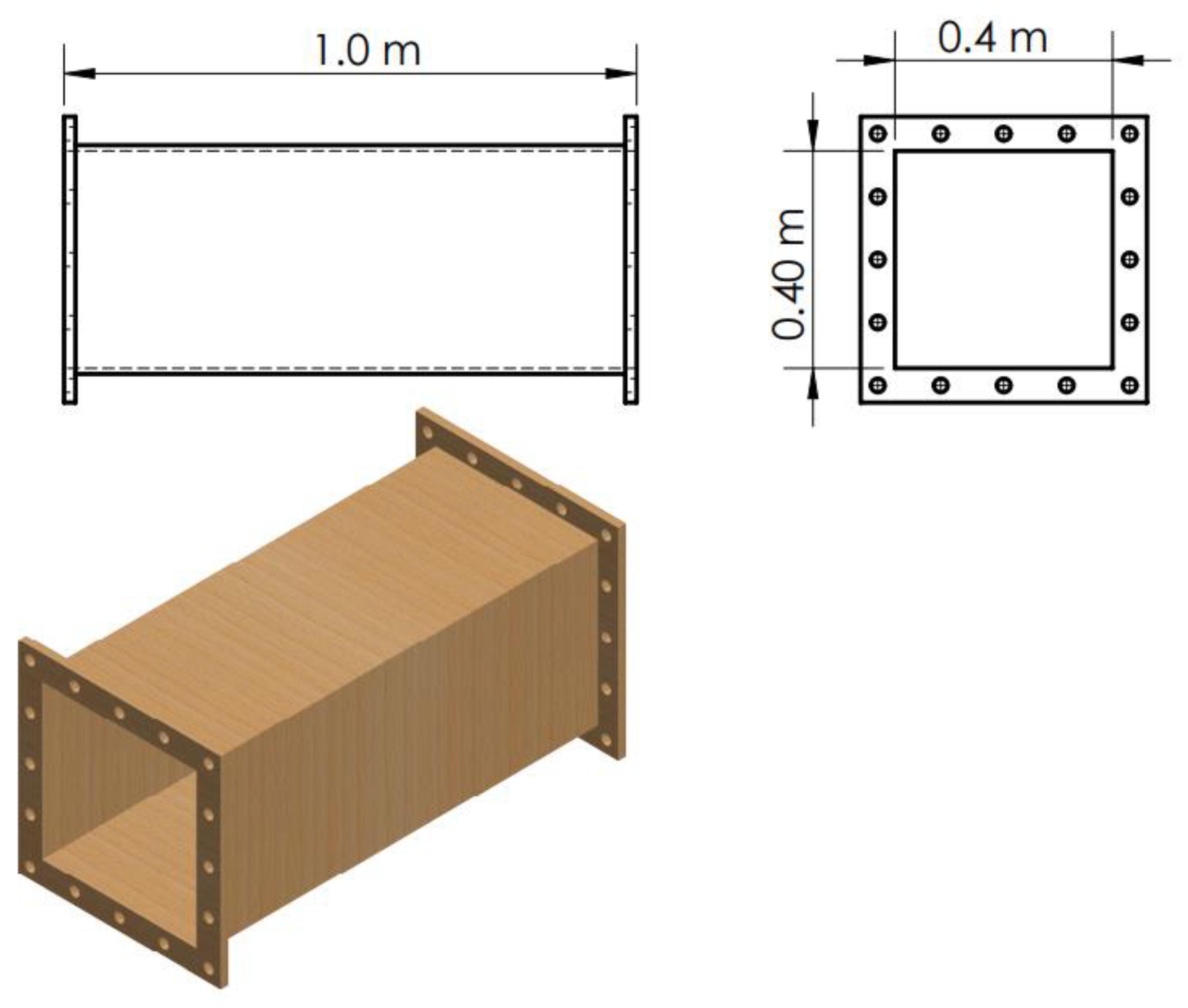
The test section is the most significant element of any wind tunnel, where measurements and observations are done on a model. The test section’s specifications and dimensions considerably influence the specifications of the other wind tunnel components, the tunnel’s total size, and the needed fan power. The test section was planned to be square (Ats = 0.4 m × 0.4 m), with a maximum desired velocity of 30 m/s within the test section, as shown in Figure 3. The test section hydraulic diameter DH,ts is 0.451 m, and the length is chosen to be (Lts = 1.0 m), yielding a length ratio ( L ts / D H , ts ) of 2.217, satisfying the condition ( 0.5 L ts D H , ts 3 ) [33].

2.1.2. Contraction Cone

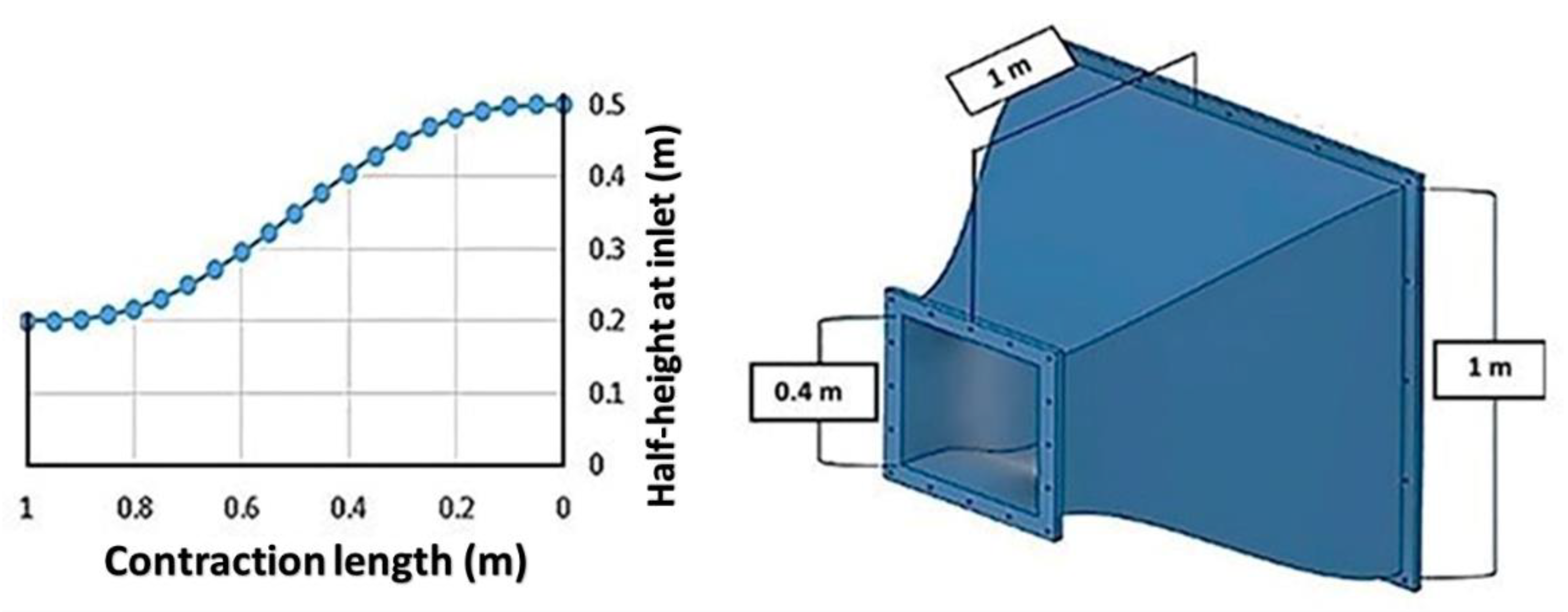
The contraction cone accelerates the flow smoothly into the test section, improving flow uniformity and reducing flow turbulence. Three important parameters must be considered in contraction cone design: the contraction ratio ( CR = A c , i A c , e ) , which is defined as the ratio of the contraction inlet area (Ac,i) to the contraction exit area (Ac,e), the contraction length to inlet side ratio   ( L c / 2 H c , i ) , and the contraction wall shapes [34]. The contraction ratio and length ratio are designed to meet Mehta and Bradshaw’s recommendations ( 6 CR 9 )   and (0.667 L c / 2 H c , i   1.79) [35]. In the current wind tunnel, the contraction exit area Ac,e equals the test section area (Ac,e = Ats = 0.4 m × 0.4 m). The contraction inlet area Ac,i is chosen to be square (Ac,i =1.0 m × 1.0 m), giving a contraction ratio of (CR = 6.25). Choose 1.0 m for the contraction length Lc, giving a length ratio of (Lc/2Hc,i =1.0), where Hc,i is the half side-length of the contraction inlet cross-section. The contraction cone’s wall profile was taken from the Bell-Metha fifth-order polynomial profile and expressed by Equation (1) [36].
y = H c , i ( H c , i H c , e ) [ 6 ( x L c ) 5 15 ( x L c ) 4 + 10 ( x L c ) 3 ]
where x denotes the stream-wise coordinate along the contraction centerline from the inlet (x = 0) to the exit ( x = L c = 1.0   m ) . The coordinate y is measured from the centerline in the normal direction and has limits of ( y = H c , i = 0.5   m ) at the contraction inlet and ( y = H c , e = 0.2   m ) at the contraction exit. Figure 4 shows the contraction wall profile for the upper half and a 3-D model of the contraction cone with all dimensions.

2.1.3. Settling Chamber (Honeycomb and Mesh Screens)

The settling chamber is an important part of the wind tunnel. It has a honeycomb section and a turbulence screen section to improve the longitudinal and lateral mean velocity distributions and make the flow more uniform before reaching the contraction section [37]. The honeycomb section is important in preventing vortices from growing and moving toward the measuring test section and reducing lateral components of mean velocities and turbulent intensities more than longitudinal components [38]. The main effect of mesh screens is to reduce the stream-wise fluctuations components of mean velocities and intensities more than lateral components.
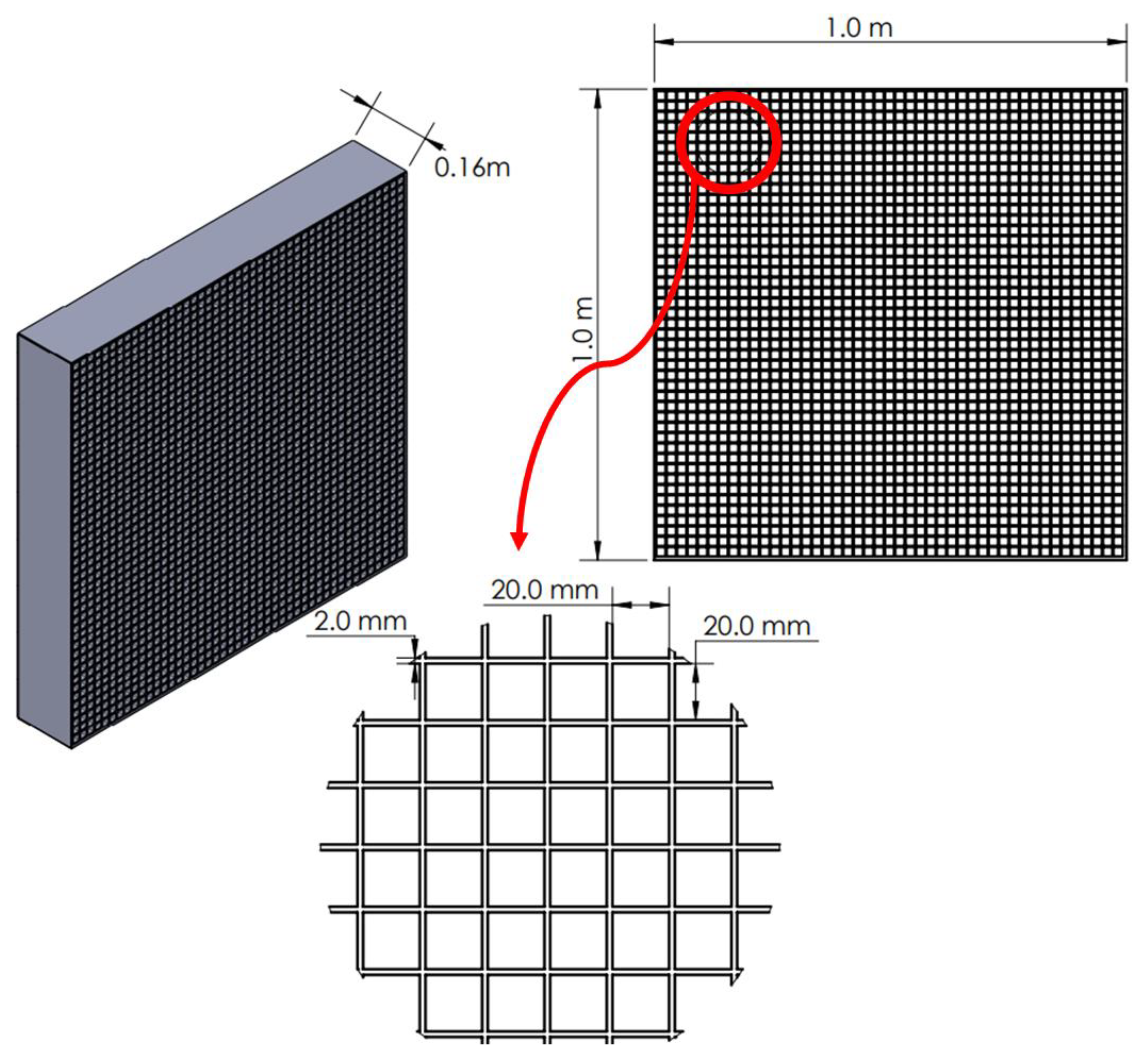
In the honeycomb design, two important parameters are considered: the honeycomb porosity ( β h = A h , f A h , t ) which is the ratio of the actual flow area of the honeycomb (Ah,f) to the total cross-section area (Ah,t) and the ratio of honeycomb length ratio ( L h   D H , cell   ) , Lh is the honeycomb length in the flow direction, and DH,cell is the hydraulic diameter of the individual honeycomb cell. The honeycomb porosity ( β h 0.8 ) and the ratio of honeycomb length in the settling chamber to individual cell hydraulic diameter, ( 6 L h   D H , cell   8 ) recommendations must be met in the design of a honeycomb [35]. In the present work, the honeycomb was designed to be square in overall size area (1.0 m × 1.0 m), with a square cell area Ah,cell of (2 cm × 2 cm), and a length Lh of 16 cm with a wall thickness of 2 mm. The total number of cells for the honeycomb is Ncell = 2067, the cell hydraulic diameter DH,cell is 2.256 cm, and the honeycomb actual flow area Ah,f is 0.826 m2. The porosity for the honeycomb βh is about 0.83, and the honeycomb length ratio for the cell is 7.11, which meets the design criteria. Figure 5 shows a 3-D model of the honeycomb of square cells in all dimensions.
For the mesh screen, the screen porosity β s is defined as the open-area ratio and given as [33,39]:
β s = ( 1 N w   D w S sc ) 2 = ( 1 D w   ρ m ) 2
where Dw is the screen wire diameter, Nw is the mesh wire number, Ssc is the settling chamber cross-section side into which the screens are inserted, and ( ρ m = N w S sc ) is the mesh wire density. The mesh density inverse represents the screen mesh divisions ( W m = 1 ρ m ) . In the current tunnel, two metallic wire screens are selected to be inserted into the settling chamber frame and positioned downstream of the honeycomb unit in the flow direction. For the selected screens, the mesh wire diameter Dw is 0.7 mm, and the distance between every two wires (wire division) Wm is 3.2 mm. The wiring density ρm is 312.5, and the mesh screen porosity value is 0.61, which satisfies the condition for the optimal mesh performance of ( 0.58 β   s 0.8 ) [35]. The mesh screen structure with its main dimensions is shown in Figure 6. The settling chamber’s cross-sectional area is the same as the contraction cone’s inlet cross-sectional area (Asc = Ac,i = 1.0 m × 1.0 m) and has a total length of 1.1 m. A distance of 20 cm was used in the design between the screens and the last screen and the entry of the contraction part.

2.1.4. Diffuser

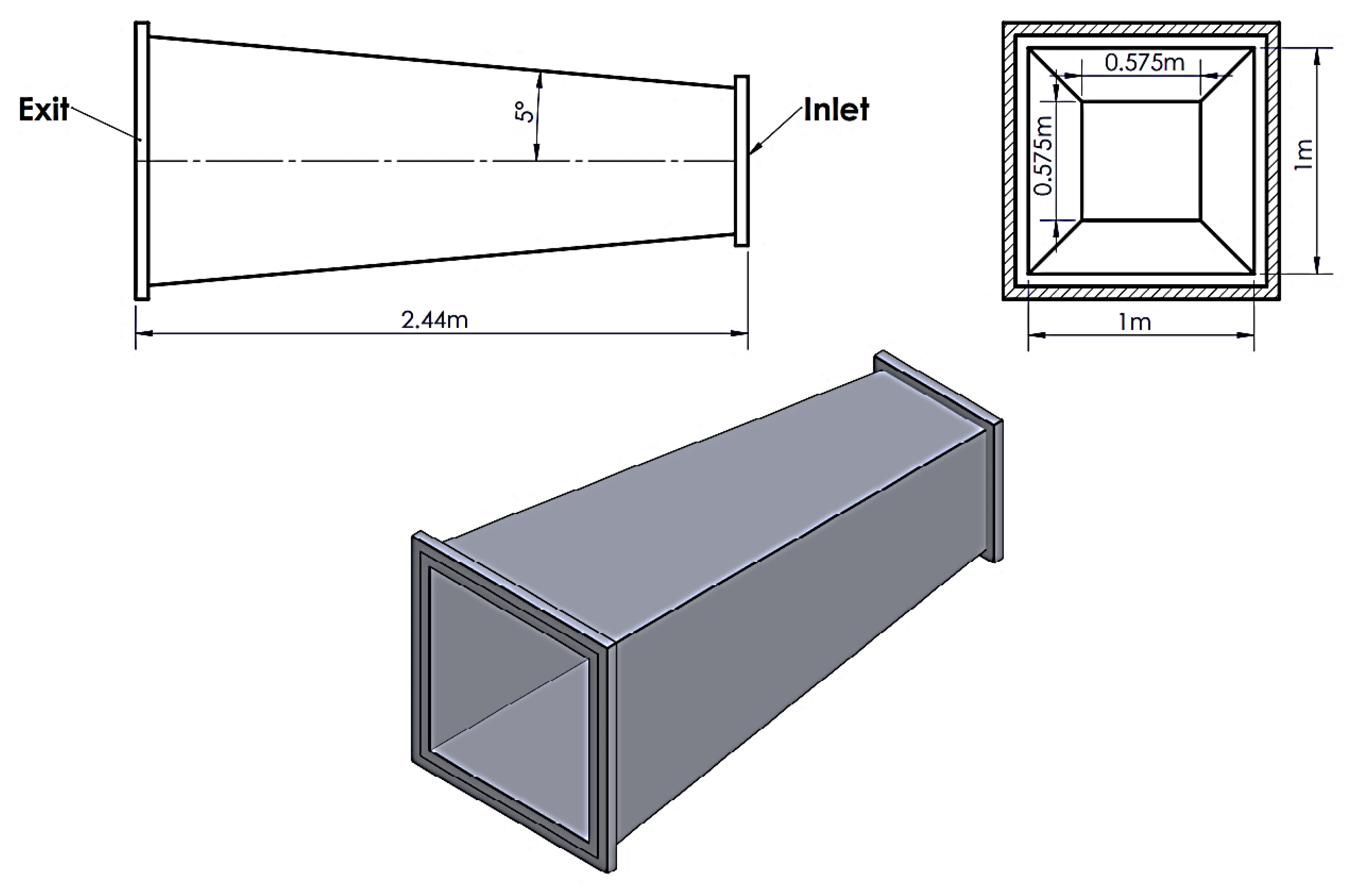
The diffuser’s main function in the wind tunnel is to reduce velocity by increasing the cross-section with as little energy loss as possible, resulting in maximum pressure recovery and lowering the load on the driving system. According to R.D. Mehta [40], the diffuser angle should be between (5°–10°) for the best flow steadiness and pressure recovery. In the current tunnel, the diffuser section is located after the fan unit and before the settling chamber section. The diffuser has an exit area Ad,e that is square and equal to the settling chamber area (Ad,e = Asc = 1.0 × 1.0 m2). The diffuser inlet area is chosen to be the square of (Ad,i = 0.575 m × 0.575 m), yielding a diffuser area ratio of ( AR = A d , e A d , i = 3.02 ), which is close to the recommended range ( 2 AR 3 ) . The diffuser walls expand from the square inlet area to the square exit area over an axial length of 2.44 m, resulting in a maximum expansion angle of (2θ ≅ 10°), which meets the design condition ( 5 ° 2 θ 10 ° ) [35]. Figure 7 shows a complete drawing of a 3-D model with all dimensions of the diffuser.

2.2. Analytical Model

This section describes in detail the analytical model used to determine wind tunnel performance, including total pressure losses ΔpL,tot, energy ratio in the tunnel circuit ER, and the operational fan power necessary PRequired. The airflow rate Q in the wind tunnel is determined by multiplying the averaged test section velocity Vts by the test section area Ats. The average velocity Vi at any section of the wind tunnel with section area Ai can be calculated from the continuity equation by assuming incompressible flow in the wind tunnel as follows:
Q = V ts   A ts = V i   A i
The total pressure loss coefficient KL,i is calculated using distinct expressions for each wind tunnel section. For the 3-D diffuser, the total pressure loss coefficient KL,d is the sum of the friction loss coefficient Kd,f and the expansion loss coefficient Kd,exp.
K L , d = K d , f + K d , exp
K d , f = ( 1 1 AR 2 ) ( f d 8 sin θ )
K d , exp = K e ( 2 θ ) ( AR 1 AR ) 2
where AR is the diffuser area ratio, θ is the half diffuser expansion angle, and fd is the friction coefficient calculated based on the diffuser inlet condition [40]. In Equation (6), Ke(2θ) is a geometrical function dependent on the cross-sectional diffuser shape (circular, square, and rectangular) and the equivalent cone angle of the section (2θ). The designed diffuser has a square cross-section area and a total expansion angle (2θ ≅ 10°), which is close to the range (3° ≤ 2θ ≤ 10°) [41], the experimental relation for the coefficient   K e ( 2 θ ) is obtained by [42] as follows:
K e ( 2 θ ) = { 1.22156 × 10 1 2.29480 × 10 2   ( 2 θ ) + 5.50704 × 10 3   ( 2 θ ) 2 4.08644 × 10 4   ( 2 θ ) 3 3.84056 × 10 5   ( 2 θ ) 4 + 8.74969 × 10 6   ( 2 θ ) 5 3.65217 × 10 7   ( 2 θ ) 6 }
For thin-walled honeycomb, the total pressure loss coefficient KL,h is given by [43] as:
K L , h = f h ( L h D H , cell + 3 ) ( 1 β h ) 2 + ( 1 β h 1 ) 2
f h = { [ 0.375 ( D H , cell ) 0.4 R e 0.1 ] ;         For   Re   275 [ 0.214 ( D H , cell ) 0.4 ] ;                                         For   Re   >   275 }
Re = ρ V h , cell   μ
V h , cell = Q N cells     A h , cell  
The friction coefficient fh is determined from a Reynolds number ReΔ, based on the surface roughness of the honeycomb material Δ and the honeycomb cell’s incoming flow speed Vh,cell.
For the empty part of the settling chamber of length (Lsc − Lh) with constant cross-section and hydraulic diameter DH,sc, the total pressure loss coefficient KL,sc is obtained from Equation (12).
K L , sc = f sc ( L sc L h ) D H , sc
where Lsc is the total settling chamber length, Lh is the length occupied by the honeycomb, and ignored the length taken by the two mesh screens.
The mesh screen’s pressure loss coefficient KL,m depends on three main parameters: the mesh factor Kmesh, the Reynolds effect coefficient KRN, and the screen porosity βs. The total pressure loss coefficient KL,m for the mesh screen is given in [44]
K L , m = K mesh   K RN     ( 1 β s ) + ( 1 β s β s ) 2
K RN = { [ 0.785 ( 1 Re w 354 ) + 1.01 ]     0 Re w 400 1.0                                                                                               Re w   400 }
Re w = ρ VD w μ
The coefficient KRN is expressed in functional form in the wire screen Reynolds number Rew. Idel’chik [42] gives the mesh factor values for new metal wire Kmesh = 1.0, for average circular metal wire Kmesh = 1.3, and for textile wire Kmesh = 2.1.
For the contraction cone, the total pressure loss coefficient KL,c is calculated based on the average friction factor fc,ave [43]
K L , c = 0.32   f c , ave ( L c D H , c   )
where Lc is the contraction cone length and DH,c is the hydraulic contraction diameter calculated at the contraction exit and equals the hydraulic diameter of test section DH,ts. The average friction coefficient fc,ave is obtained based on the average of the Reynolds numbers at the entrance and exit of the contraction.
For the wind tunnel test section with a constant area section, the total pressure loss coefficient KL,ts due to friction is given by
K L , ts =   f ts L ts D H , ts
The total pressure loss in each wind tunnel section ΔPL,i is calculated by multiplying the total pressure loss coefficient KL,i with the dynamic pressure qi in each section.
p L , i = K   L , i   q i = K   L , i   ( 1 2 ρ V i 2 )
where ρ is the airflow density. Hence, Vi is the average flow velocity in the wind tunnel sections at the inlet components and the contraction section at the exit.
The total pressure loss for all wind tunnel components, ΔpL,comp, can be obtained by summing all the pressure losses over the wind tunnel components.
p L , comp = p L , i
The total pressure loss in the wind tunnel circuit ΔpL,tot is the sum of the total pressure losses for all wind tunnel components and the pressure loss by exiting the wind tunnel ΔpL,e and is given by Equation (20) as:
p L , tot = p L , comp + p L , e
The test section is opened to the atmosphere for the current blower wind tunnel, and the flow’s kinetic energy is discharged. The pressure loss at the tunnel exit is given by Equation (21) and is equal to the dynamic pressure at the test section exit.
P L , e =   q ts = 1 2 ρ V ts 2
The axial fan’s power PFan required to maintain a steady airflow inside the wind tunnel at a specified test section speed Vts is equal to the total energy losses occurring in the flow through the wind tunnel circuit ET,circuit as follows:
P Fan = E T ,   circuit = Q   ( p L , tot )   RF
where RF is a reserve factor used to allow for additional losses through leaks and joints. The actual drive power required is dependent on the efficiency of the fan/motor system using Equation (23).
P Required = P Fan ƞ total
where ηtotal is the total efficiency of the driving unit ( η total = η motor   × η VFD   × η fan ) .
The energy ratio of the wind tunnel (ER) is a measure of the total efficiency of the wind tunnel and is defined as the ratio of the flow energy in the test section ( E ts = Q   q ts ) to the total energy dissipated in the wind tunnel circuit (ET,circuit) and expressed as:
ER = E ts E T ,   circuit

2.3. Wind Tunnel Measurements

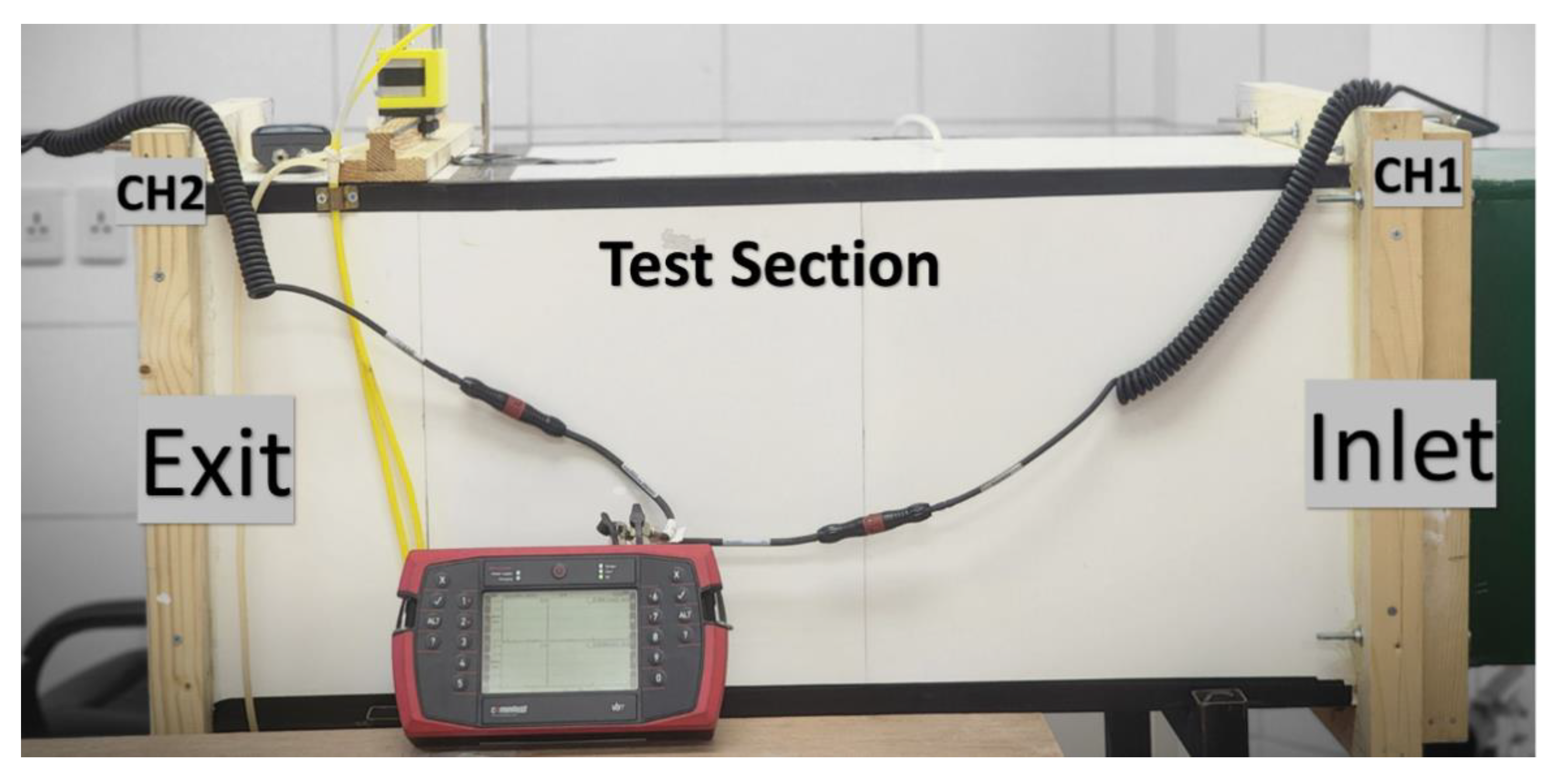
Before a model or object is tested in a wind tunnel, the flow quality, noise, and vibration in the test area of the present blower wind tunnel must be confirmed. Experiments are conducted to examine the flow uniformity by measuring velocity profiles inside the empty test section for different fan frequencies regulated by a speed controller (VFD), with the corresponding setting of 10–50 Hz. The Pitot tube was mounted on the simple slide probe traversing mechanism that moves inside the test section at any specified point in the measuring plane, as shown in Figure 8. To meet the present study’s goal, a rig has been installed in the test section to collect data on the tunnel’s flow noise and vibration. The vibration is acquired using a vibration data collector (COMMTEST, General Electric, Florida, USA). The testing rig comprises a noise meter that measures ambient noise levels generated by the tunnel’s axial fan and construction. In addition, two accelerometers were used to measure the tunnel structure at the inlet and exit sections of the tunnel, as shown in Figure 8.
In this study, the velocity measurements are taken in a vertical (y-z) plane in the middle of the wind tunnel’s test section, 50 cm away from the exit of the contraction section and normal to the wind tunnel centerline stream-wise axis. The vertical plane measurements were taken point by point between the test section walls at (38 × 38) locations with divisions Δy = Δz = 10 mm. The stream-wise wind velocity was evaluated from the pressure measurements at the measurement points using a Pitot-static probe for various fan frequencies from 10 Hz to 50 Hz. The measurements were recorded when the temperature of the wind tunnel stabilized at an ambient temperature of 295 K [45].

3. Results and Discussion

This section presents and discusses the current wind tunnel’s experimental and analytical data results. The measured ambient pressure p = 100.4 kPa, temperature T = 295 K, and the airflow are assumed to be incompressible, with constant air density, ρ = 1.1859 kg/m3, dynamic viscosity, μ = 1.8205 × 10 5 kg/(m. s) conditions, which are referenced for all experimental and analytical results. The results from experiments in wind tunnel testing for wind speed, noise, and vibration at various fan frequencies are presented.

3.1. Wind Speed Analysis

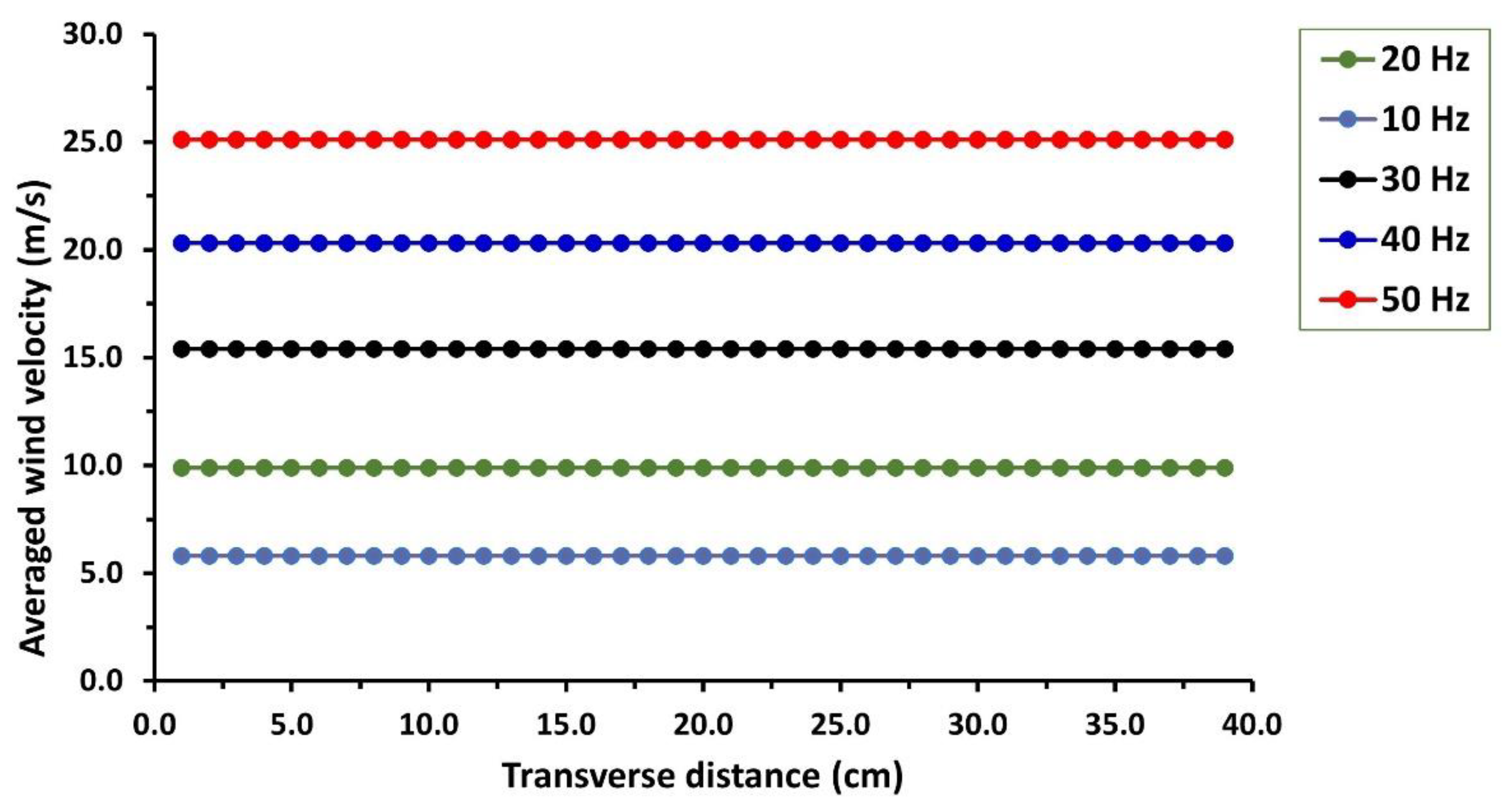
The measured average wind speed in the empty test section is evaluated for all specified points at different fan frequencies in the measured plane section. Due to the same velocity values along the measuring plane points, the velocity results are presented for the points in the middle of the measuring section between the two side walls of the test section for each fan frequency. Figure 9 shows the measured mean stream-wise (longitudinal) velocity profiles of the wind flow at the midplane in the transverse direction between the two side walls of the test section. Wind velocity measurement in stream-wise directions revealed consistent readings in both vertical and lateral directions. It was found that the wind velocity test section increased as the fan frequency increased. From the figure, the mean wind velocity achieved in the empty test section flow ranges from 5.8 m/s to a maximum average velocity of 25.1 m/s for fan motor frequencies ranging from 10 to 50 Hz, according to wind tunnel measuring results. It is seen from the figure at various fan frequencies that a uniform flow velocity profile was observed within the majority of the test section core region (90%) due to the effect of the settling chamber (honeycomb and two screens) and contraction before the test section. The no-slip condition formed a boundary layer at the test section walls. The corresponding Reynolds number Re values based on the measured averaged wind velocity, test section hydraulic diameter, and airflow properties at laboratory room conditions are in the range of ( 1.71 × 10 5 Re 7.37 × 10 5 ) . This indicates that a highly turbulent flow regime exists in the measuring test section with a small confined viscous sublayer near the walls of the test section. Therefore, the velocity was not measured in this region.
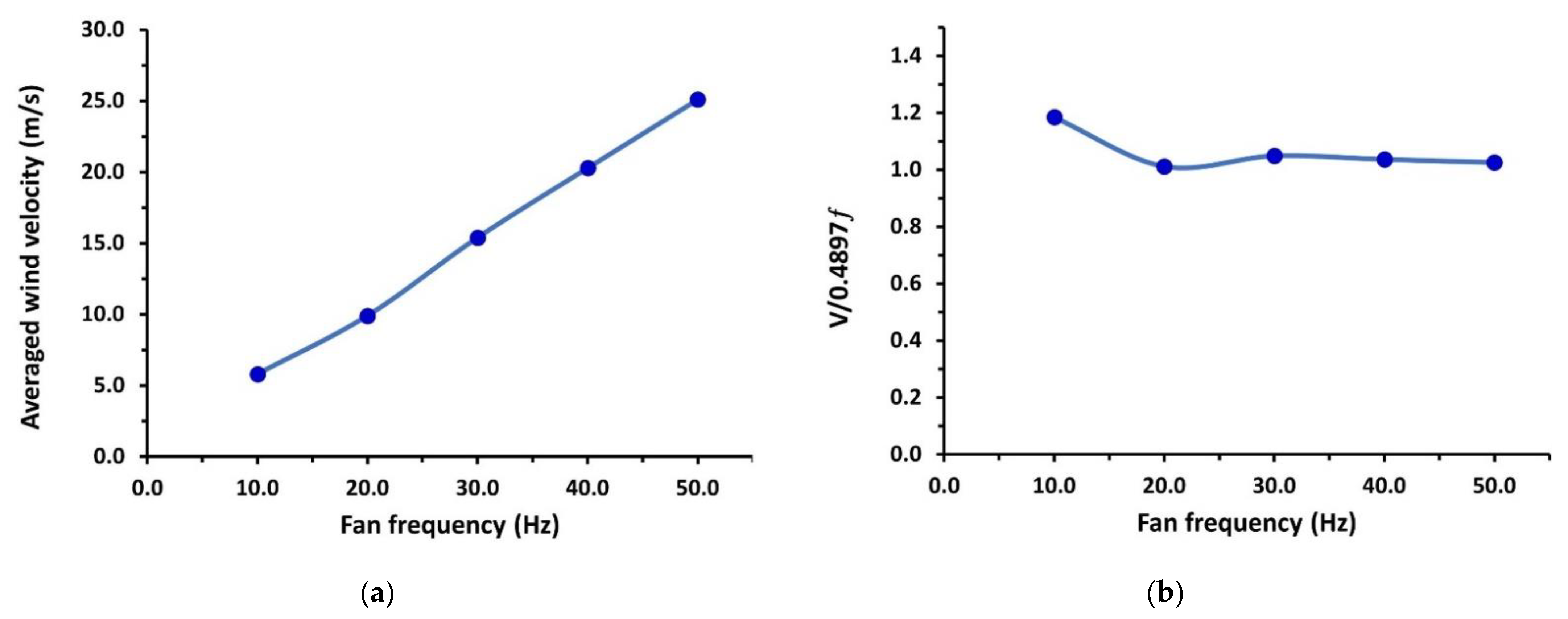
To demonstrate the performance of the current wind tunnel, Figure 10a shows the variation of the measured averaged wind velocity in the test section Vts with the fan motor frequency ƒ. It is seen that the test section’s average velocity increases with the fan frequency. A linear relationship can fit the measured velocity data as in Equation (25) between wind velocity Vts (m/s) and the fan motor frequency (ƒ) in Hz. This fitting relationship for the velocity can be used in future aerodynamic tests to select any test velocity with the corresponding fan motor frequency. Figure 10b shows the measured velocity normalized by (0.4897 ƒ), which gives constant values around 1.03 for frequencies of 20 Hz to 50 Hz and gives 1.18 at 10 Hz. It is noted that the regression Equation (25) is fitted to the entered velocity measurement; thus, the initial value is set from 10 Hz up to 50 Hz. Therefore, it is valid for the measured range.
V ts = 0.4897   f + 0.6076
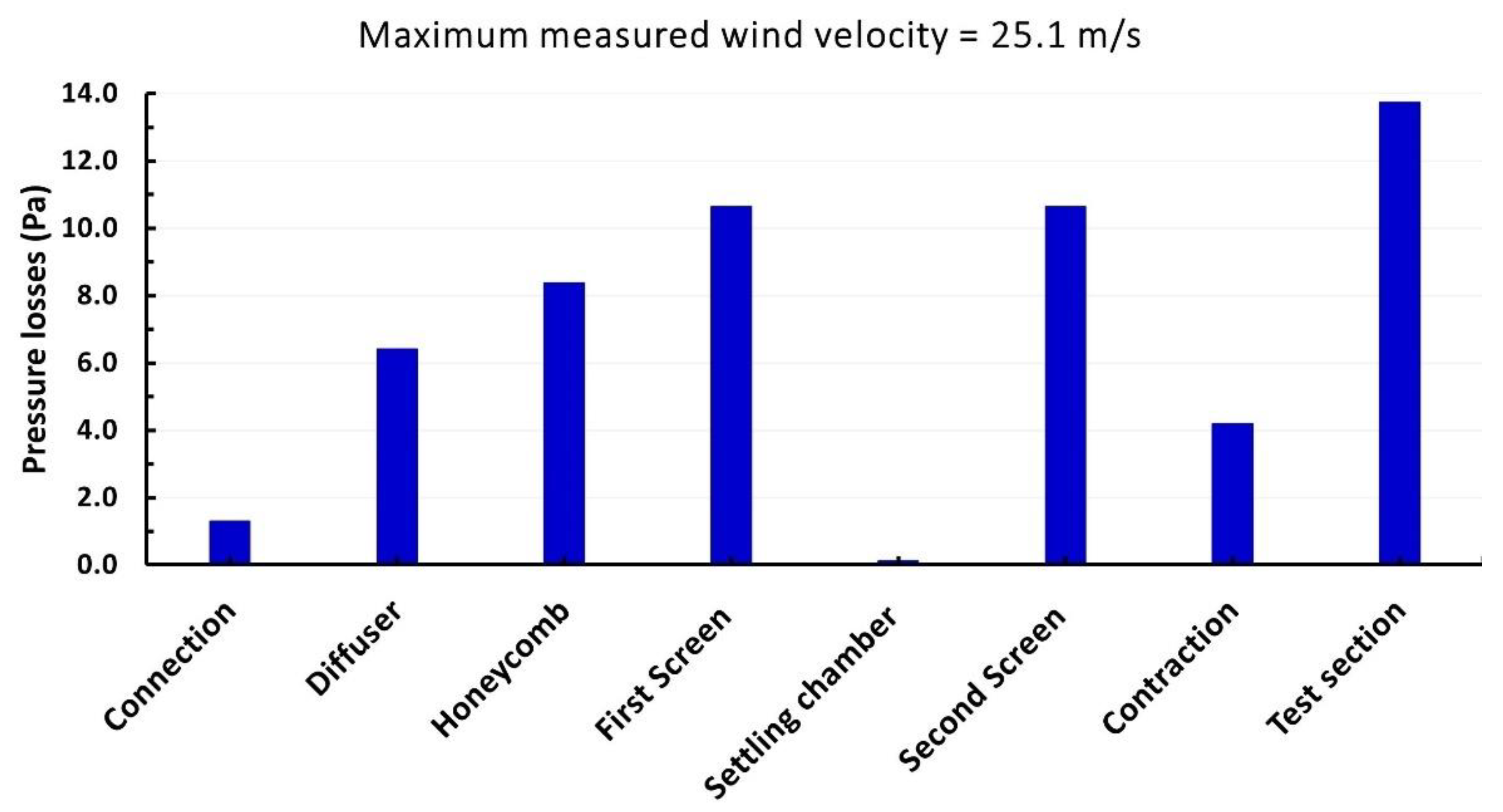
Wind tunnel performance data are acquired from the analytical model for all the measured mean velocities in the wind tunnel’s test section. After measuring the mean velocity of the test section at various fan frequencies, the mean velocity in the other wind tunnel sections can be calculated from the continuity equation. The pressure loss coefficient, KLi total pressure losses for each wind tunnel section ΔPl,i and the overall pressure losses for all components, are calculated for all the measured wind velocities. Table 2 summarizes the data for the maximum measured wind velocity (25.1 m/s) in the test section. Additionally, Figure 11 displays the contribution of the wind tunnel sections to pressure losses at the measured maximum mean velocity.
In the prediction results, (RF = 1.1) was taken as the reserve factor for air leakage from the current wind tunnel. The wind tunnel circuit power loss ET,circuit was calculated for all the measured mean velocities in the test section and is represented in Figure 12. This figure shows the increase in wind tunnel circuit power loss with increasing wind speed. The predicted energy ratio ER for the current wind tunnel was obtained at various measured speeds and is shown in Figure 13. The figure shows that the energy ratio is almost constant for all speeds, with an average value of about 79% ± 0.5.

3.2. Structural Vibration Analysis

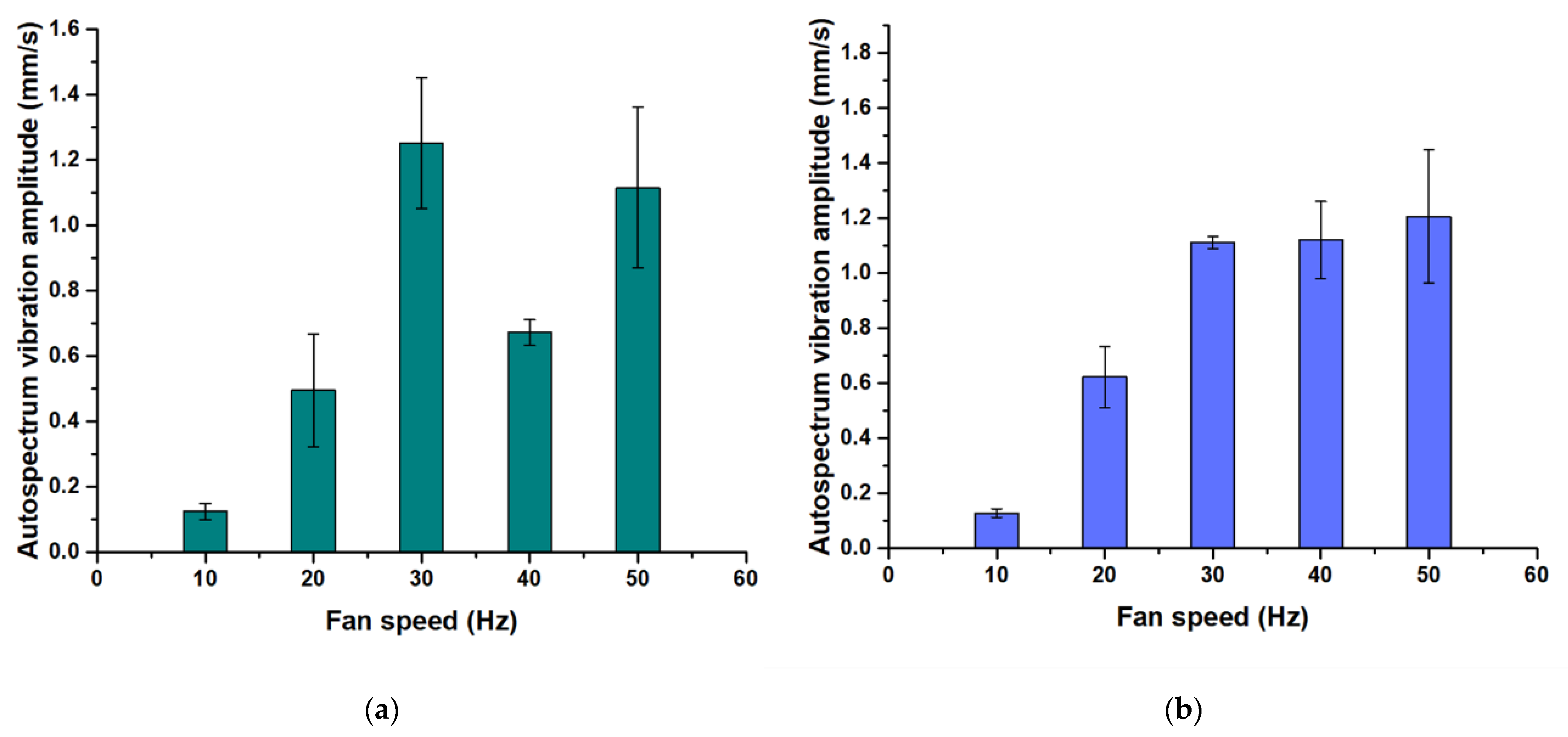
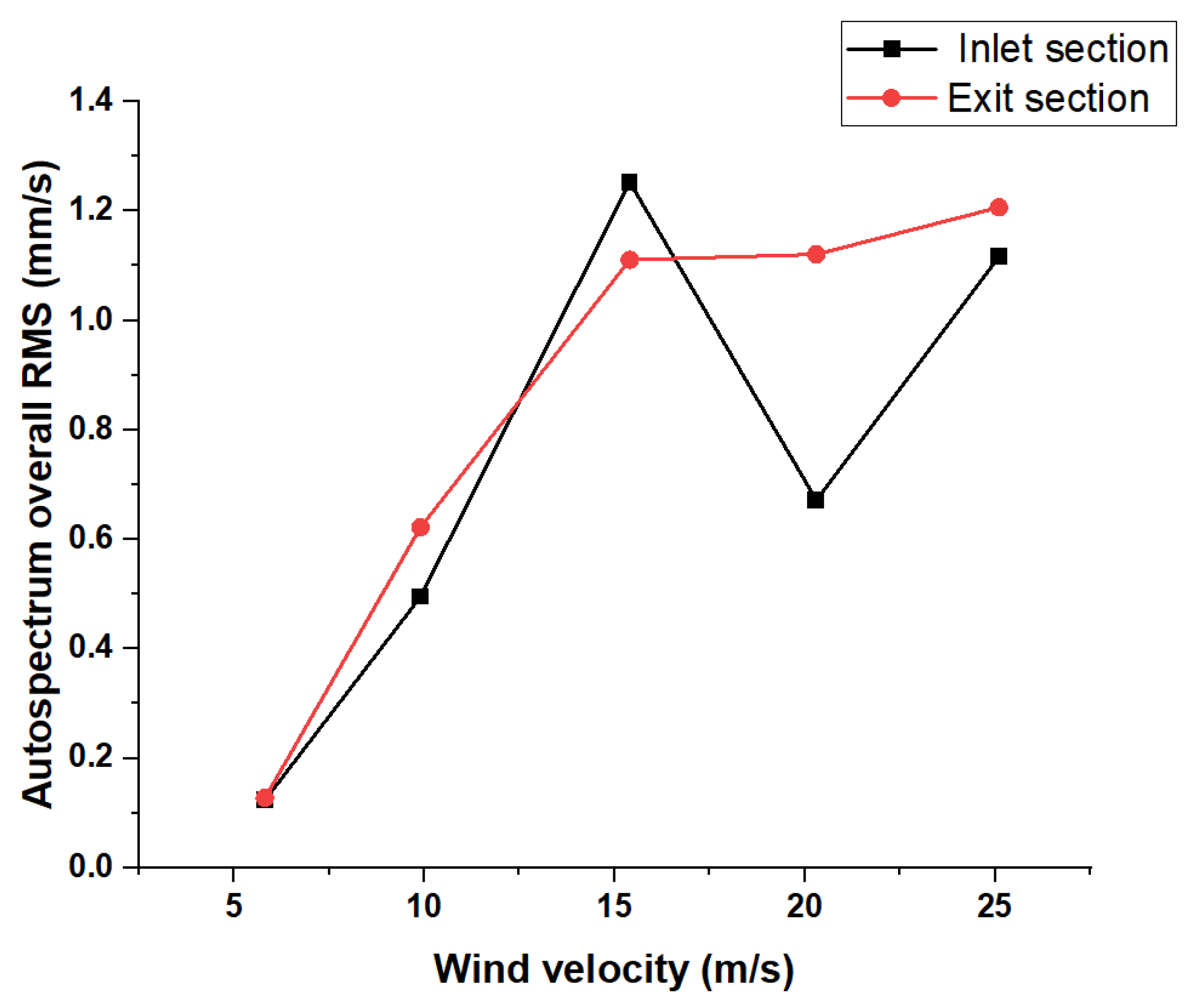
The effect of fan frequency on the vibrations of the wind tunnel structure was measured as a total value in mm/s using accelerometers attached to the wind tunnel structure at various locations along the axial direction of the test section. In the outlet test section of the wind tunnel, it was found that as the fan frequency increased, the vibrations also increased. Figure 14a shows the relationship between the motor fan frequency (Hz) and the corresponding total vibration amplitude of the auto spectrum in mm/s in the inlet test section. A significantly higher amplitude was observed at a fan frequency of 30 Hz. This led to the measurement being repeated more than four times to determine the exact vibration value of this speed. However, an expected set of vibration amplitudes was observed in the output range, as shown in Figure 14b. The bump test is one of the most basic methods for determining the natural frequencies of a structure. The wind speed affects the structure’s vibration. When the wind speed is high, the structure vibrates more, and this can be observed in both measured locations in the inlet and exit test sections, as shown in Figure 15. This is because the wind whips around the structure, making it vibrate; however, when the wind speed is low, the structure vibrates less. This is because the air does not move around the structure as much. When this happens, the wind has less effect, so the structure does not vibrate as strongly. The inlet section shows fluctuations in the resultant vibration more than the exit section, which can be attributed to the stability of the flow at the end of the test section.
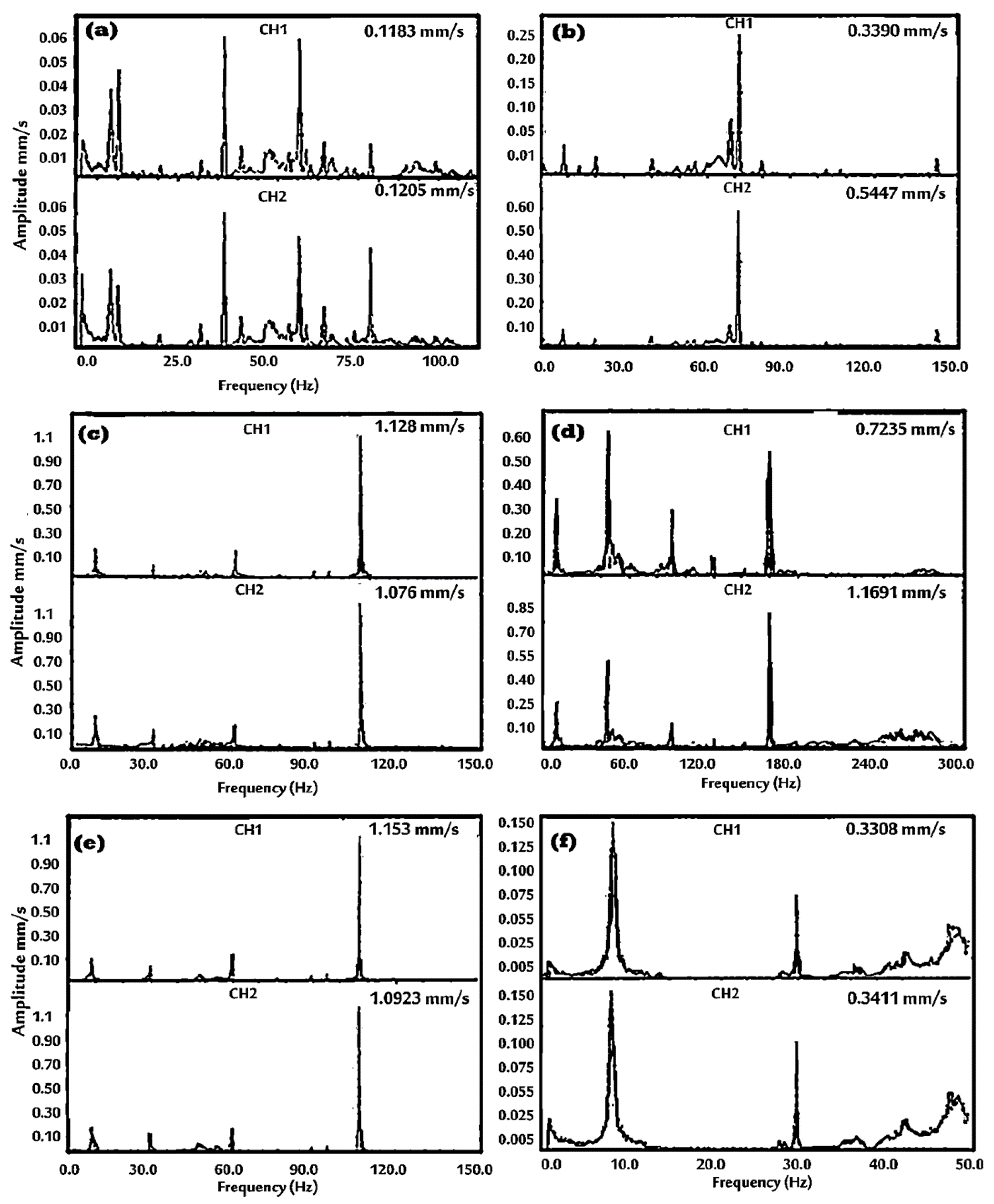
Resonance occurs when an excited frequency meets a structure’s natural frequency. In the present case, the structure’s resonant frequency before the inlet section is about 30 Hz. Therefore, when the fan frequency reaches the same value, a dominant amplitude is observed in the auto-spectrum analysis. Figure 16 shows the auto-spectrum plots of the studied fan frequency, where channels 1 and 2 represent the readings of the accelerometers placed at the inlet and outlet positions of the test section, respectively. In each case, the fundamental frequency has more than three harmonics. Therefore, Figure 16a–c represents the fan frequency at 10, 20, and 30 Hz, respectively, with the significant amplitude observed at the fourth harmonic. In addition, it was found that increasing the fan frequency increased its resonance frequency but decreased the number of observed peaks in the power spectrum. When the fan speed is low, up to 30 Hz, the auto-spectrum shows more peaks than when the fan speed is high. It can be concluded that the changes in the spectral density of the airflow in the wind tunnel are related to the changes in fan frequency.
On the other hand, it was observed that the fan frequency at 40 and 50 Hz had a significant amplitude at half orders; thus, the values recorded were at the 4.5th and 2.5th, respectively. The structure’s resonant frequency appeared to be 30 Hz. These results explain the increase in the vibration amplitude of the fan frequency at such a value. Total vibration amplitude was measured at a frequency of 10 Hz. Thus, it was found that the fan frequency directly affects the total amount of vibration generated by the wind tunnel. For example, the total vibration also increased as the fan’s speed increased. The maximum vibration was observed at a fan frequency of 50 Hz, while the minimum amount was seen at a fan frequency of 10 Hz. When the highest frequency was measured, i.e., 50 Hz, the maximum total vibration amplitude was obtained at 1.15 mm/s. This observation is explained as follows: At lower frequencies, the overall vibration level increases with fan frequency because the rotor blades are not moving fast enough to induce significant vibrations.

3.3. Noise Analysis

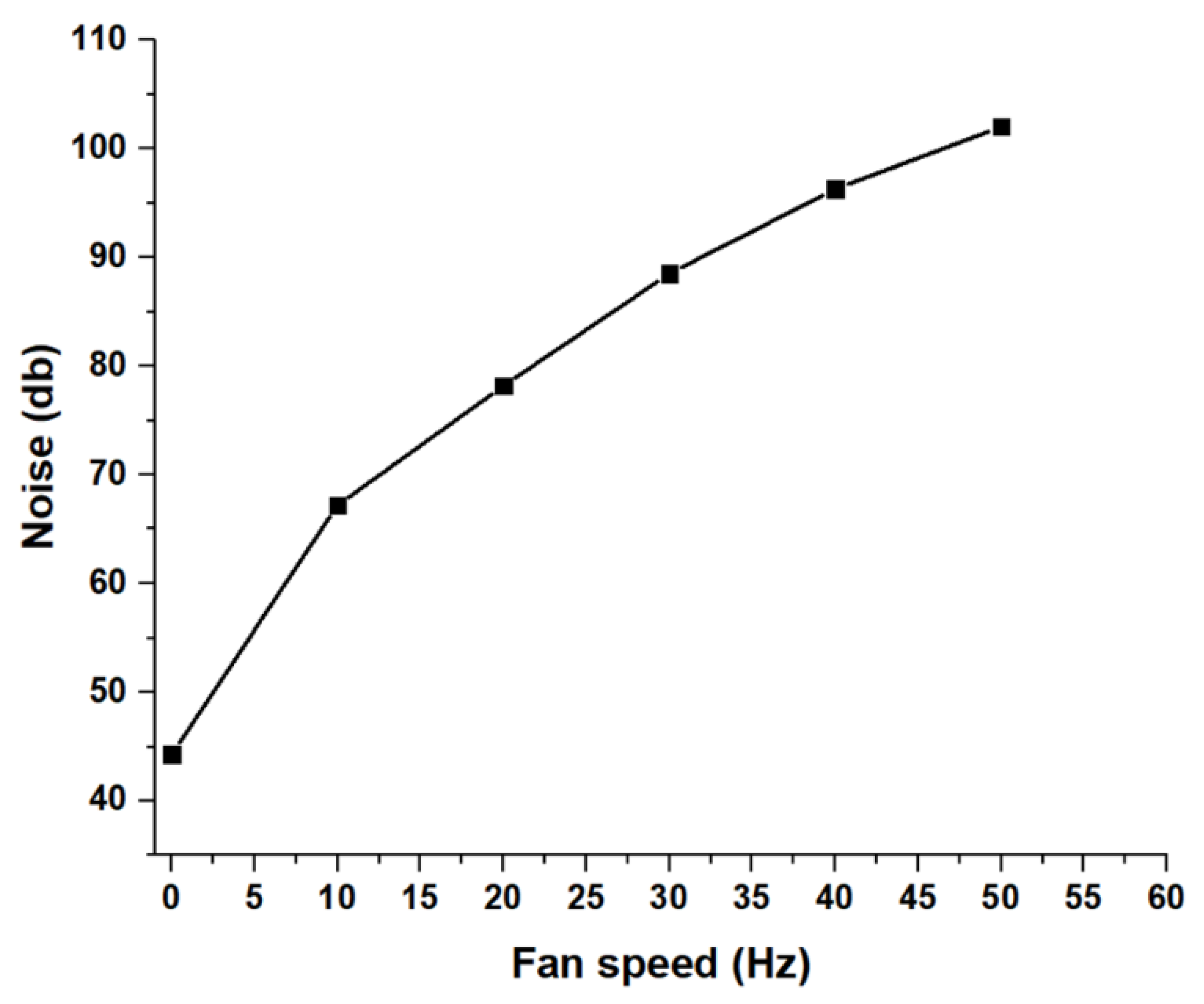
Wind tunnels and their acoustics refer to the sounds produced within the tunnel and by the axial fan. This can have a negative effect on the accuracy of wind tunnel measurements because fluctuations in the flow can affect the velocity of the air flowing through the tunnel, thus disturbing the airflow around the object under test. The inhomogeneity in the flow refers to any variation in the flow path’s cross-sectional area. The design of the wind tunnel can also contribute to generating velocity noise if it is not optimized for this purpose. A sound wave is a combination of numerous frequencies with a particular wavelength and intensity. As the speed at which the blade is spinning increases, the sound wave’s intensity also increases. The noise meter is used to measure the noise value for each case. Noise levels tend to increase significantly as the operating speed of the fan increases. To reduce the noise generated by a fan, it is advisable to operate it at low speeds. A slower operating speed will reduce the overall noise output of the cooling fan and result in substantial savings in energy costs. In addition, slow operating speeds are likely to reduce the wear and tear on the components of the fan, thereby extending its service life and reducing maintenance requirements. The relationship between the axial fan frequency and the generated noise is illustrated in Figure 17. As the fan frequency increases, the noise level also increases. The most important observation in this curve is that the fan’s critical frequency lies at 30 Hz, with a corresponding noise value of 80 dB. According to occupational health and safety organizations such as OSHA, NEBOSH, IOSH, etc., exposures at or above this level are considered hazardous.

4. Conclusions

In this research work, a low-speed open-circuit blower wind tunnel has been designed, constructed, and tested for flow, noise, and vibration at various fan frequencies. The design process for the main parts of the wind tunnel is explained in detail, based on recommendations and design rules. On this basis, the required fan power is estimated, and an axial fan is selected for the current wind tunnel. The wind tunnel components’ construction and assembly processes are discussed. The wind velocity inside the empty test section is tested at various fan frequencies to test the wind tunnel’s uniformity. The test section achieved a maximum operating speed of 25.1 m/s, close to the desired maximum value of 30 m/s. The velocity profile for this wind tunnel indicated a turbulent flow regime with a maximum Reynolds number of 7.37 × 10⁵.
In the range of measurements (10–50 Hz), there is a linear relationship between the average wind speed and the frequency of the fan motor. The predicted total losses in the tunnel components are calculated, and the energy ratio is quite high and equal to 0.79, indicating a successful wind tunnel design. The effect of axial fan frequency on the wind velocity inside the wind tunnel is significant. At a high fan frequency, the wind velocity is higher; therefore, the pressure waveform is broader. This increases the vibrations of the structure due to higher pressure levels and altered flow fields within the wind tunnel. Therefore, a well-designed experimental setup should account for increased wind speeds at high fan frequencies and their effect on structure vibration. The factors affecting the average ventilation rate or the airflow rate through a duct are the air inlet area, the distance between the inlet and outlet, the area of the diffuser, and the velocity of the air flowing through the duct.

Author Contributions

Conceptualization, S.S.A.A.; methodology, S.S.A.A., A.-H.S.S.S. and E.B.M.; formal analysis, S.S.A.A. and E.B.M.; investigation, S.S.A.A. and E.B.M.; writing—original draft preparation, S.S.A.A., E.B.M. and A.-H.S.S.S.; project administration, S.S.A.A. All authors have read and agreed to the published version of the manuscript.

Funding

This research was funded by the Deanship of Scientific Research (DSR), King Abdulaziz University, Jeddah, grant number (G: 623-135-1441).

Data Availability Statement

Not applicable.

Acknowledgments

The authors acknowledge the Deanship of Scientific Research (DSR), King Abdulaziz University, Jeddah, for technical and financial support.

Conflicts of Interest

The authors declare no conflict of interest.

References

  1. Rau, M.; Bächlin, W.; Plate, E. Detailed design features of a new wind tunnel for studying the effects of thermal stratification. Atmos. Environ. Part A Gen. Top. 1991, 25, 1257–1262. [Google Scholar] [CrossRef]
  2. Xie, D.; Xiao, P.; Cai, N.; Sang, L.; Dou, X.; Wang, H. Field and Wind Tunnel Experiments of Wind Field Simulation in the Neutral Atmospheric Boundary Layer. Atmosphere 2022, 13, 2065. [Google Scholar] [CrossRef]
  3. Hegade, K.P.N.; Natalia, R.; Wehba, B.; Mittal, A.; Bhat, R.B.; Packirisamy, M. Design and study of mini wind tunnel for microsystems fluid interaction under low Reynolds number flows. SN Appl. Sci. 2020, 2, 850. [Google Scholar] [CrossRef] [Green Version]
  4. Qu, X.; Ren, Z.; Yang, W.; Luo, Y. The axial fan design and commissioning test with nonuniform inlet flow. J. Phys. Conf. Ser. 2022, 2280, 012026. [Google Scholar] [CrossRef]
  5. Castegnaro, S. Aerodynamic Design of Low-Speed Axial-Flow Fans: A Historical Overview. Designs 2018, 2, 20. [Google Scholar] [CrossRef] [Green Version]
  6. Yong, T.H.; Dol, S.S. Design and Development of Low-Cost Wind Tunnel for Educational Purpose. IOP Conf. Ser. Mater. Sci. Eng. 2015, 78, 012039. [Google Scholar] [CrossRef] [Green Version]
  7. Hussain, I.Y.; Ali, A.H.; Majeed, M.H.; Sarsam, W.S. Design, Construction and Testing of Low Speed Wind Tunnel with Its Measurement and Inspection Devices. J. Eng. Univ. Baghdad 2011, 17, 1550–1565. [Google Scholar]
  8. Chanetz, B. A century of wind tunnels since Eiffel. Comptes Rendus Mécanique 2017, 345, 581–594. [Google Scholar] [CrossRef]
  9. Yanovych, V.; Duda, D.; Horáček, V.; Uruba, V. Research of a wind tunnel parameters by means of cross-section analysis of air flow profiles. In AIP Conference Proceedings; AIP Publishing: Usti nad Labem, Czech Republic, 2019; Volume 2189. [Google Scholar] [CrossRef]
  10. Ismail, E.; Pane, A.; Rahman, R.A. An open design for a low-cost open-loop subsonic wind tunnel for aerodynamic measurement and characterization. HardIwareX 2022, 12, e00352. [Google Scholar] [CrossRef]
  11. Verma, N.; Baloni, B.D. Numerical and experimental investigation of flow in an open-type subsonic wind tunnel. SN Appl. Sci. 2019, 1, 1384. [Google Scholar] [CrossRef] [Green Version]
  12. Leifsson, L.; Koziel, S. Simulation-driven design of low-speed wind tunnel contraction. J. Comput. Sci. 2015, 7, 1–12. [Google Scholar] [CrossRef]
  13. Fang, F.-M.; Chen, J.; Hong, Y. Experimental and analytical evaluation of flow in a square-to-square wind tunnel contraction. J. Wind. Eng. Ind. Aerodyn. 2001, 89, 247–262. [Google Scholar] [CrossRef]
  14. Almeida, O.D.; Miranda, F.C.D.; Ferreira Neto, O.; Saad, F.G. Low Subsonic Wind Tunnel-Design and Construction. J. Aerosp. Technol. Manag. 2018, 10. [Google Scholar] [CrossRef]
  15. Abdelhamed, A.; Yassen, Y.-S.; ElSakka, M. Design optimization of three dimensional geometry of wind tunnel contraction. Ain Shams Eng. J. 2015, 6, 281–288. [Google Scholar] [CrossRef] [Green Version]
  16. Celis, B.; Ubbens, H.H. Design and Construction of an Open-circuit Wind Tunnel with Specific Measurement Equipment for Cycling. Procedia Eng. 2016, 147, 98–103. [Google Scholar] [CrossRef] [Green Version]
  17. Khan, D.; Bjernemose, J.H.; Lund, I.; Bebe, J.E. Design and construction of an open loop subsonic high temperature wind tunnel for investigation of SCR dosing systems. Int. J. Thermofluids 2021, 11, 100106. [Google Scholar] [CrossRef]
  18. Yi, W.; Zhou, P.; Fang, Y.; Guo, J.; Zhong, S.; Zhang, X.; Huang, X.; Zhou, G.; Chen, B. Design and characterization of a multifunctional low-speed anechoic wind tunnel at HKUST. Aerosp. Sci. Technol. 2021, 115, 106814. [Google Scholar] [CrossRef]
  19. Niu, X.; Chen, H.; Li, Y.; Jia, X.; Zhang, Y.; Yong, X.; Li, C. Design and performance of a small-scale acoustic wind tunnel at Wenzhou University for aerodynamic noise studies. Appl. Acoust. 2022, 199, 109010. [Google Scholar] [CrossRef]
  20. Bian, H.; Tan, Q.; Zhong, S.; Zhang, X. Assessment of UAM and drone noise impact on the environment based on virtual flights. Aerosp. Sci. Technol. 2021, 118, 106996. [Google Scholar] [CrossRef]
  21. Lilley, G. The Prediction of Airframe Noise and Comparison with Experiment. J. Sound Vib. 2001, 239, 849–859. [Google Scholar] [CrossRef]
  22. Teff-Seker, Y.; Berger-Tal, O.; Lehnardt, Y.; Teschner, N. Noise pollution from wind turbines and its effects on wildlife: A cross-national analysis of current policies and planning regulations. Renew. Sustain. Energy Rev. 2022, 168, 112801. [Google Scholar] [CrossRef]
  23. Katinas, V.; Marčiukaitis, M.; Tamašauskienė, M. Analysis of the wind turbine noise emissions and impact on the environment. Renew. Sustain. Energy Rev. 2016, 58, 825–831. [Google Scholar] [CrossRef]
  24. Vitalii, Y.; Daniel, D. Structural Deformation of a Running Wind Tunnel Measured By Optical Scanning. Stroj. Časopis-J. Mech. Eng. 2020, 70, 181–196. [Google Scholar] [CrossRef]
  25. Abbas, A.; Elwali, W.; Haider, S.; Dsouza, S.; Sanderson, M.; Segan, Y. CAE Cooling Module Noise and Vibration Prediction Methodology and Challenges; SAE International: Warrendale, PA, USA, 2020; Available online: https://www.sae.org/publications/technical-papers/content/2020-01-1262/ (accessed on 6 February 2023).
  26. Mo, J.-O.; Choi, J.-H. Numerical Investigation of Unsteady Flow and Aerodynamic Noise Characteristics of an Automotive Axial Cooling Fan. Appl. Sci. 2020, 10, 5432. [Google Scholar] [CrossRef]
  27. Brooks, T.F.; Pope, D.S.; Marcolini, M.A. Airfoil Self-Noise and Prediction. In Technical Report; Hampton, V., Ed.; NASA Reference Publication USA: Washington, DC, USA, 1989; p. 1218. Available online: https://ntrs.nasa.gov/citations/19890016302 (accessed on 6 February 2023).
  28. Park, S.M.; Ryu, S.-Y.; Cheong, C.; Kim, J.W.; Park, B.I.; Ahn, Y.-C.; Oh, S.K. Optimization of the Orifice Shape of Cooling Fan Units for High Flow Rate and Low-Level Noise in Outdoor Air Conditioning Units. Appl. Sci. 2019, 9, 5207. [Google Scholar] [CrossRef] [Green Version]
  29. Rynell, A.; Chevalier, M.; Åbom, M.; Efraimsson, G. A numerical study of noise characteristics originating from a shrouded subsonic automotive fan. Appl. Acoust. 2018, 140, 110–121. [Google Scholar] [CrossRef]
  30. Franzke, R.; Sebben, S.; Bark, T.; Willeson, E.; Broniewicz, A. Evaluation of the Multiple Reference Frame Approach for the Modelling of an Axial Cooling Fan. Energies 2019, 12, 2934. [Google Scholar] [CrossRef] [Green Version]
  31. Cattafesta, L.; Bahr, C.; Mathew, J. Fundamentals of Wind-Tunnel Design. In Encyclopedia of Aerospace Engineering; 2010. Available online: https://www.researchgate.net/profile/Louis-Cattafesta/publication/230271809_Fundamentals_of_Wind-Tunnel_Design/links/5a0d7a51a6fdcc39e9bfe324/Fundamentals-of-Wind-Tunnel-Design.pdf (accessed on 6 February 2023).
  32. Liu, P.; Xing, Y.; Guo, H.; Li, L. Design and performance of a small-scale aeroacoustic wind tunnel. Appl. Acoust. 2017, 116, 65–69. [Google Scholar] [CrossRef]
  33. Barlow, J.B.R.; Pope, A.W.H. Low-Speed Wind Tunnel Testing. In Aerospace Engineering/Mechanical Engineering; John Wiley & Sons: Hoboken, NJ, USA, 1999; Volume 3. [Google Scholar]
  34. Kao, Y.-H.; Jiang, Z.-W.; Fang, S.-C. A Computational Simulation Study of Fluid Mechanics of Low-Speed Wind Tunnel Contractions. Fluids 2017, 2, 23. [Google Scholar] [CrossRef] [Green Version]
  35. Mehta, R.D.; Bradshaw, P.M.D. Design rules for small low speed wind tunnels. Aeronaut. J. 1979, 83, 443–453. [Google Scholar]
  36. Bell, J.H.; Mehta, R.D. Contraction Design for Small Low-Speed Blind Tunnels; Stanford University: Stanford, CA, USA, 1989; p. 39. [Google Scholar]
  37. Kulkarni, V.; Sahoo, N.; Chavan, S.D. Simulation of honeycomb–screen combinations for turbulence management in a subsonic wind tunnel. J. Wind. Eng. Ind. Aerodyn. 2011, 99, 37–45. [Google Scholar] [CrossRef]
  38. Hamzah, H.; Jasim, L.M.; Alkhabbaz, A.; Sahin, B. Role of Honeycomb in Improving Subsonic Wind Tunnel Flow Quality: Numerical Study Based on Orthogonal Grid. J. Mech. Eng. Res. Dev. 2021, 44, 352–369. [Google Scholar]
  39. Pereira, J.D. Wind Tunnels: Aerodynamics Models and Experiments; Nova Science Publisher’s: Hauppauge, NY, USA, 2011. [Google Scholar]
  40. Mehta, R. The aerodynamic design of blower tunnels with wide-angle diffusers. Prog. Aerosp. Sci. 1979, 18, 59–120. [Google Scholar] [CrossRef]
  41. Munson, B.R. Fundamentals of Fluid Mechanics, 7th ed.; John Wiley & Sons: Hoboken, NJ, USA, 2013. [Google Scholar]
  42. Idelchik, I.E. Handbook of Hydraulic Resistance; Research Institute for Gas Purification: Moscow, Russia, 2008. [Google Scholar]
  43. Wattendorf, F.L. Factors Influencing the Energy Ratio of Return Flow Wind Tunnels. In Proceedings of the Fifth International Congress for Applied Mechanics, Cambridge, UK, 29 July 1938. [Google Scholar]
  44. Eckert, W.T.; Mort, K.W.; Jope, J. Aerodynamic Design Guidelines and Computer Program for Estimation of Subsonic wind Tunnel Performance; 1976. Available online: https://ntrs.nasa.gov/citations/19770005050 (accessed on 6 February 2023).
  45. Benedetti, D.M.; Veras, C.A.G. Wind-Tunnel Measurement of Differential Pressure on the Surface of a Dynamically Inflatable Wing Cell. Aerospace 2021, 8, 34. [Google Scholar] [CrossRef]
Figure 1. A typical image of the assembled small low-speed open-circuit blower wind tunnel.
Machines 11 00360 g001
Figure 2. Typical axial fan and 3-D model of a driving unit with an axial fan.
Machines 11 00360 g002
Figure 3. The 3-D model of the test section.
Machines 11 00360 g003
Figure 4. Contraction cone: upper half profile and 3-D model.
Machines 11 00360 g004
Figure 5. The 3-D model of the honeycomb with square cells.
Machines 11 00360 g005
Figure 6. The mesh screen structure with the main dimensions.
Machines 11 00360 g006
Figure 7. The 3-D model of the diffuser.
Machines 11 00360 g007
Figure 8. The structural vibration measurement using a vibration data collector with two-channel inputs.
Machines 11 00360 g008
Figure 9. The measured mean velocity at the midplane in the transverse direction between the two side walls of the test section.
Machines 11 00360 g009
Figure 10. (a) The measured averaged wind velocity in the test section versus the fan frequency; (b) The normalized velocity versus the fan frequency.
Machines 11 00360 g010
Figure 11. Wind tunnel component pressure losses for the maximum measured wind velocity (25.1 m/s).
Machines 11 00360 g011
Figure 12. Wind tunnel circuit power loss versus test section measured velocity.
Machines 11 00360 g012
Figure 13. Wind tunnel energy ratio versus test section measured velocity.
Machines 11 00360 g013
Figure 14. The vibration amplitude versus the wind tunnel fan frequency (a) in the inlet test section and (b) exit test section.
Machines 11 00360 g014
Figure 15. The vibration amplitude fluctuation versus the wind velocity.
Machines 11 00360 g015
Figure 16. Autospectrum vibration response of the wind tunnel structure at the inlet (channel 1-CH1) and exit (channel 2-CH2) (ae) is the frequency domain signature for 10, 20, 30, 40, and 50 Hz fan frequencies, and (f) the bump test response.
Machines 11 00360 g016
Figure 17. The relationship between the wind tunnel fan frequency and the corresponding measured noise.
Machines 11 00360 g017
Table 1. Specifications of the axial fan unit and variable frequency drive (VFD).
Axial Fan UnitVariable Frequency Drive (VFD)
SpecificationValueSpecificationValue
Motor supply3-phaseInput voltage220 V (±15%) AC
Motor Power7.5–8.6 kWOutput voltage380 V/AC
Max motor frequency60 HzInput frequency0–50/60 Hz
Number of fan blades10Output frequency0–650 Hz
Inner diameter0.57 mThe input stage1 phase for 220 V
Outer diameter0.63 mThe output stage3 phases for 380 V
Casing length0.67 mModel9100-1T3-00750G
Pressure rise Δp970 PaManufacturerShenzhen NFlixin Electric Co., Ltd. (Guangdong, China)
Flow rate, Q16,740 m3/h
ManufacturerGebhardt Ventilatorren—D-74638 Waldenburg
TypeARMF2-580-2D-22
Table 2. The total pressure loss results for the wind tunnel components at the measured averaged maximum velocity (25.1 m/s).
Wind Tunnel ComponentKL,i ΔpL,i (Pa)
Connecting0.0151.289
Diffuser0.0736.413
Settling chamber (empty part)0.0130.126
Honeycomb0.5978.372
First screen1.11310.643
Second screen1.11310.643
Contraction cone0.0114.187
Test section0.03713.738
The components’ total pressure loss, ΔpL,comp (Pa)55.412
Disclaimer/Publisher’s Note: The statements, opinions and data contained in all publications are solely those of the individual author(s) and contributor(s) and not of MDPI and/or the editor(s). MDPI and/or the editor(s) disclaim responsibility for any injury to people or property resulting from any ideas, methods, instructions or products referred to in the content.