Article

Development and Experiment of Clamp Type Submarine Cable Inspection Robot

College of Mechanical and Electrical Engineering, Harbin Engineering University, Harbin 150001, China
*
Author to whom correspondence should be addressed.
Machines 2023, 11(6), 627; https://doi.org/10.3390/machines11060627
Submission received: 30 April 2023 / Revised: 26 May 2023 / Accepted: 31 May 2023 / Published: 6 June 2023
(This article belongs to the Section Machine Design and Theory)

Abstract

:
Relying on the research and development project of an auxiliary device for a submarine cable to cross a steel pipeline, with regard to a long-distance submarine cable crossing a pipeline, combined with a pipe-climbing robot and the laying of the submarine cable, this paper developed a detection robot that walks along the outer wall of the cable inside the submarine casing. The non-enclosed four-bar linkage mechanism is adopted, a stepper motor is used to drive a roller to walk on the submarine cable, the diameter change of the submarine cable is recorded in real-time, the damage of the submarine cable is detected when it is moved along the submarine cable, and the walking experiment is carried out. The submarine cable diameter measurement verification experiment showed that the outer wall detection robot of the submarine cable could stably travel on the submarine cable, and at the same time, could measure the real-time diameter of the submarine cable and record the actual condition of the submarine cable through video.

1. Introduction

In the Bohai Sea area of China, with the development of marine resources, the seabed laying machine has been gradually developed [1,2], in order to avoid disturbance of the topography and reduce the adverse impact on the surrounding marine ecological environment caused by the submarine cable laying construction. In an area less than 250 m away from the red line of a protected area, the seabed surface excavation operation is not carried out, but horizontal directional drilling with the crossing construction method can be used [3,4]. Under the conditions where the submarine cable is dragged inside an external pipeline, if it is necessary to overcome the frictional force of the contact length of more than 1 km between the submarine cable and the inner wall of the protective tube, the traction force of the submarine cable will greatly exceed the maximum allowable tensile force of the submarine cable, causing mechanical damage to the submarine cable [5,6,7]. In response to this situation, the Shore Power Project of Bohai Oilfield proposed a research and development project for an auxiliary device for towing the submarine cable through the steel pipeline; this topic is derived from this project. Aiming for long-distance submarine cables passing through pipelines, combined with pipe-climbing robots and underwater cable laying, a detection robot for the outer wall of submarine cables inside submarine casings was developed to detect the damage to the submarine cable when it is being towed.
Pipe-climbing robots are mainly used in industrial production, cable inspection, and chemical fields by virtue of their form of walking outside the pipe [8]. The pipeline robots are mainly divided into three category types according to how they hold the pipeline: bionic, mechanical holding [9], and gravity self-locking [10]. According to the way of movement, mechanical clinging robots can be divided into four sub-categories, namely wheel type, crawler type, foot type, and parallel mechanism type, as shown in Figure 1 [11,12].
In 2003, R. Aracil et al. of Spain developed a parallel mechanism crawling robot, which could realize two movement modes outside and inside the tube [13]. In 2009, C. Cohoi et al. from Korea designed a mobile robot for outside the pipe, which used the cylinder as the power to make the robot clamp and move on the pipe, with the robot able to pass through a bend area [14]. In the same year, Noohi et al. of Iran studied a pipe-climbing robot using three sets of wheels evenly distributed around the pipe as the drive. The module adopted a triangular truss on the periphery, which had high stability [15]. In 2019, Yuan Xiaoqiang et al. of China designed a cable-appearance inspection robot with a modular design, which was composed of three sections, and each section was linked by pins. The pressure was changed by adjusting the nut on the T-shaped seat, and a camera could be installed on each section to detect the cable without dead ends [16]. In 2020, Muhammad Bilal Khan et al. of Thailand developed a worm-like crawling robot, which relied on the electromagnetic feet on its two legs to crawl on the surface of metal pipes, and there was a passive foot cap under the electromagnetic feet imitating an inchworm, to adapt to the circular surface [17]. In 2021, Kazuyuki Ito et al. of Japan developed a robot that could climb a variety of columnar objects. This robot could walk on the ground reliably and could flexibly adapt to pipes of various diameters [18]. These research results provide reference and reference for the development of detection robots.
Under working conditions, the submarine cable is in direct contact with the inner wall of the pipeline, so the inspection robot has little space for activities in the pipeline; the problems brought by waterproofing and remote control also need to be considered. Among the existing pipe-climbing robots in the world, based on their mechanical structure [19,20,21,22,23,24,25], the parallel mechanism type pipe climbing robot, the wheeled holding pipe climbing robot, and the bionic snake type pipe climbing robot are unable to adapt to the direct contact between a submarine cable and pipeline. Due to insufficient activity space, the clawing tubular climbing robot and the bionic inchworm robot cannot be directly applied to this scenario; thus, it is necessary to design a new type of submarine cable inspection robot to adapt to this environment.
After referring to the structural design of the pipe climbing robot, combined with the working conditions of the outer wall of the submarine cable in the submarine casing studied, a wheel-driven non-encircling-structure detection robot for the outer wall of the submarine cable was developed in this paper. The arm mechanism, the drive mechanism, and the underwater electronic chamber were designed, and the motion performance and measurement function verification experiments were carried out. The results verify the reliability of the detection robot, which provides a basis for further research on the submarine cable outer wall detection robot.

2. Design Scheme of Submarine Cable Towing Auxiliary Device

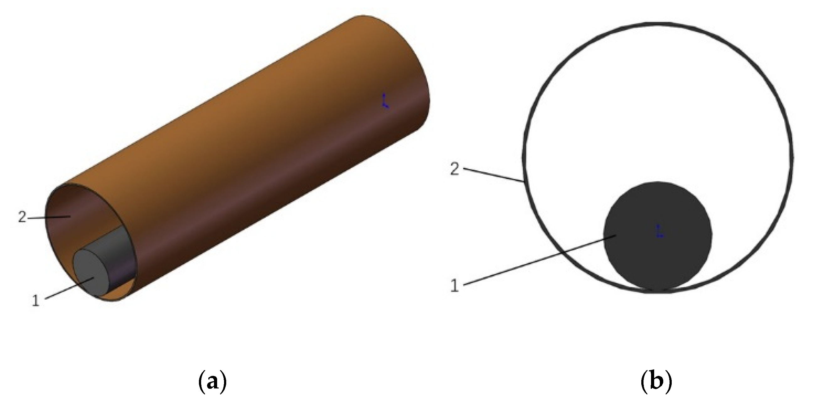
2.1. Detection Robot Parameter Determination and Working Condition Analysis

The submarine cable outer wall detection robot designed in this paper aims to detect damage to the submarine cable in the pipeline. The external pipeline is a steel pipeline with an outer diameter of ϕ630 mm and an inner diameter of ϕ614 mm. The location of the submarine cable and external pipeline is modeled in 3D, as shown in Figure 2.
Combined with the actual working conditions and appeal requirements of the project, the main performance index parameters of the robot designed in this paper are:
  • inner diameter of the pipeline: D = 614 mm;
  • outer diameter of the submarine cable: d = 252 mm;
  • pipeline material: welded steel pipe;
  • maximum walking speed: v = 10 m/min;
  • control distance: 1000 m;
  • power supply: AC 220 V power supply;
  • operation: detect drag damage along the cable and can take pictures and record.

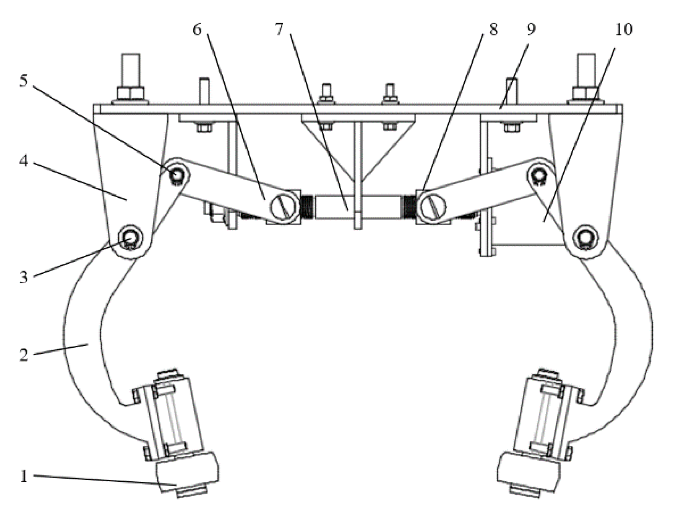
2.2. Structural Design of Inspection Robot

The submarine cable outer wall detection robot, as a whole, includes a wheel arm module, an underwater electronic module, a driving wheel module, a driven wheel module, and a profile frame, as shown in Figure 3. There are two groups of wheel arm modules, as shown in Figure 4. Each group of clamping arms, connecting rods, clamping wheels, and transmission nuts have two pieces, respectively, which together form a plane four-bar mechanism, and the clamping arms and the connecting rods are two in one. The group is hinged through the pin shaft of the clamping arm and finally forms two clamping arms on both sides of the submarine cable. The lead screw controls the clamping and unclamping action of the submarine cable through the encoder motor, and the clamping arm can be adjusted at any time to provide clamping force so that the detection robot can stably move forward on the submarine cable. A waterproof cover is designed outside the encoder motor to ensure water tightness of the motor.

3. Theoretical Analysis of Mechanics of Submarine Cable Towing

The process of towing the submarine cable is divided into three stages for analysis. The first stage is the towing stage. The cable-laying vessel puts the submarine cable into the sea and tows it until the target position. The second stage is the transition stage. The submarine cable reaches the supporting frame, and then the towing wire rope and the towing net sleeve are stably connected through the connecting shackle. The third stage is the back-towing stage. The hoist starts to work, towing the wire rope to drive the submarine cable, and continues to drag until the submarine cable reaches the target position [26].

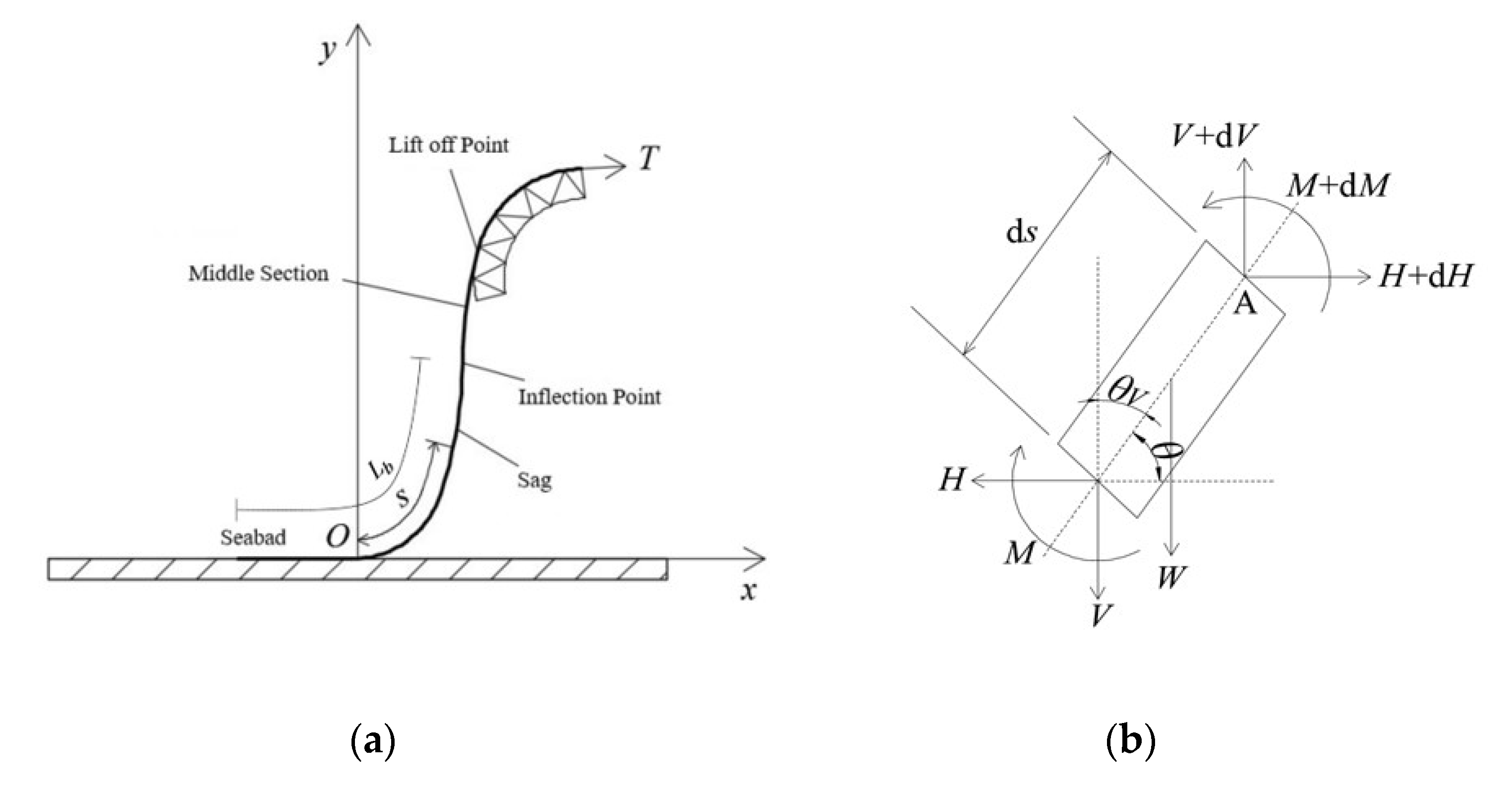
3.1. Theoretical Analysis of Mechanics in Submarine Cable Towing Stage

In the towing stage of the submarine cable, the catenary theory is used to analyze the submarine cable. Assuming that the submarine cable is a flexible structure, ignoring the influence of its bending stiffness and torsional deformation [27]. In view of the large axial stiffness (EA), the axial deformation of the submarine cable can be ignored, and the self-weight of the submarine cable is assumed to be uniformly distributed along the arc length.
Set the contact point between the submarine cable and the seabed as the origin O, establish the x-axis and y-axis along the horizontal and vertical directions, respectively, and take the beam element at any point below the top of the submarine cable. In the beam element, H represents the horizontal component and V represents the vertical component of the tension of the suspended part of the submarine cable. W is the weight of the beam element, including the buoyancy action, M is the bending moment of the cable, θ is the angle between the beam element and the horizontal direction, θV is the angle between the beam element and the vertical direction. The stress balance of the beam element is shown in Figure 5.
According to the moment balance of the beam element, taking the moment at point A, the equilibrium differential equation is obtained:
H sin θ d s + M V cos θ d s ( M + d M ) W ( d s ) 2 cos θ / 2 = 0
In the formula, s—the distance from the touchdown point to any point below the reversal point, m.
Further simplification, ignoring higher-order terms, yields:
H sin θ d s V cos θ d s d M = 0 .
Horizontal direction:
d H d s = 0 ,   H = c o n s t .
From the beam theory, the following two equations are obtained:
M E I = d θ d s ,   d V d s = W .
In the formula, EI—bending stiffness of submarine cable, N/m.
From the geometric relationship:
d y d x = sin θ ,   d x d s = cos θ
Combining the above relational formula, Formula (2) is differentiated twice to get:
E I d 2 θ d s 2 H sin θ + V cos θ = 0
E I d 2 ( θ V ) d s 2 H sin θ V + V cos θ V = 0 .
Define a series of dimensionless coefficients:
z = s L b ( 0 z 1 ) ,   h = H W L b ,   α 2 = E I W L b 3 ,   m = M L E I = d θ d z
In the formula, Lb—the total length of the submarine cable below the inflection point, m.
Carry out the dimensionlessization of Formula (7) to obtain a new dimensionless equilibrium differential equation:
α 2 d 2 ( θ V ) d z 2 + h cos θ V z sin θ V = 0
The natural catenary method ignores the pipe bending stiffness, i.e., α2 = 0. Equation (8) is further simplified as:
h cos θ V = z sin θ V
From Equation (9), solve the angle of any point below the inflection point:
θ ( z ) = π 2 tan 1 ( h 2 ) = π 2 cot 1 ( z h )
Synthesize the horizontal and vertical components of the tension to get the cable tension:
T ( z ) = W L b ( z 2 + h 2 ) 1 / 2
Substituting the data of Equation (11) into the calculation, the relationship between the submarine cable tension T(z) and Lb and the angle θ can be obtained, as shown in Figure 6.
The submarine cable tension T is mainly affected by the total length Lb of the submarine cable below the inflection point, and it increases with the increase of Lb, that is, it increases with the increase of the depth of the submarine cable laying. At the same time, it is also positively related to the angle θ. It increases with the increase of the angle θ, that is, the tension of the submarine cable at the touchdown point is the smallest, and the closer it is to the inversion point, the greater the tension.

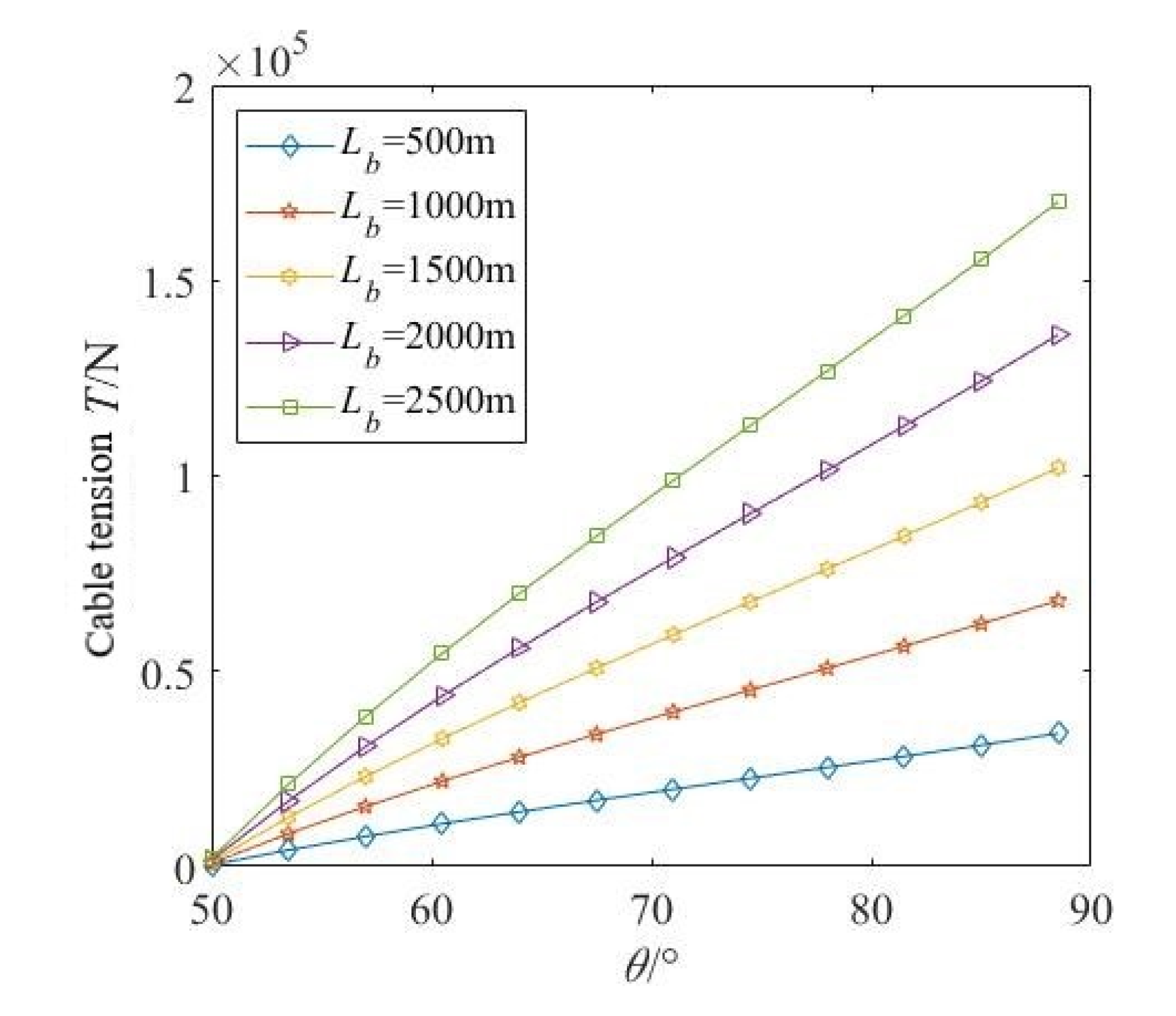
3.2. Theoretical Analysis of Mechanics of Submarine Cable Traction Stage

Based on the following assumptions, this paper establishes a calculation model for the return drag resistance of submarine cables:
(1)
Use the segment method to calculate and analyze the force of the submarine cable. This method divides the submarine cable into multiple segments according to the pipeline trajectory, and each segment is in the vertical plane, regardless of the direction change in the horizontal plane;
(2)
When the pipeline trajectory is bent around the corner point, the curved section of the pipeline is symmetrical about the corner bisector. On both sides of the corner bisector, the submarine cable is tangent to the pipe wall;
(3)
There is no mutual influence between the winch effect and the submarine cable bending effect.
In order to establish the resistance model of the submarine cable back towing process, it is necessary to analyze the factors affecting the resistance of the towing cable in the whole process. The resistance of the submarine cable towing mainly comes from the following three aspects:
  • The resistance caused by the weight of the submarine cable outside the pipe;
  • The resistance caused when part of the submarine cable in the pipe passes through the straight section;
  • The resistance caused when part of the submarine cable in the pipe passes through the bending section.
It can be seen from this that the resistance of submarine cable towing when it enters the node i can be calculated by the following formula [28]:
T i = ( T g ) i + ( T s ) i + k = 1 i 1 Δ T k f
where
(Tg)i—the resistance caused by the weight of the submarine cable outside the pipe, N;
(Ts)i—the resistance caused when part of the submarine cable in the pipe passes through the straight section, N;
k = 1 i 1 Δ T k f —the resistance caused by part of the submarine cable in the pipe passing through the bending section, N.
(1)
Resistance caused by the weight of the submarine cable outside the pipe
In order to calculate the resistance of this part of the submarine cable, the force analysis of the submarine cable outside the pipeline is performed as a whole. As shown in Figure 7, when the submarine cable enters the i-th node, the length of the submarine cable outside the pipeline is ( L k = 1 i 1 L k ) . Take the submarine cable outside No. 1 node in Figure 7 as an isolator.
Then the resistance caused by the part of the submarine cable outside the pipe at the i-th node is:
( T g ) i = ( T g ) 1 = ( w p μ g cos α 0 + w p sin α 0 ) ( L k = 1 i 1 L k )
where
wp—the weight of the submarine cable per meter, N;
g—the weight of the submarine cable, N;
μg—the friction coefficient between the pipeline and the submarine cable;
L—the total length of the submarine cable, m;
Lk—the length of the kth segment of the pipeline, m;
α0—the angle between the axis of the outer part of the submarine cable tube and the horizontal line, °.
(2)
The resistance of the submarine cable through the straight section
For the calculation of the resistance of the submarine cable passing through the straight section in the pipeline, it is mainly the frictional resistance with the pipeline caused by the weight of the submarine cable. Calculated by the following formula:
( T s ) k 1 = w p μ g cos α k 1 L k 1 + w p sin α k 1 L k 1
where
Lk−1—the length of this segment, m;
αk−1—the angle between the horizontal line and the axis of the pipeline, °.
(3)
The resistance of the submarine cable through the bending section
In the i-th curved segment of the pipeline trajectory, the central angle corresponding to the curved segment is k (the vertical lines of the straight line segments on both sides of the curved segment are drawn at the endpoints on both sides of the curved segment, and the acute angle between the two vertical lines is the central angle). The tensile force on the side near the entrance of the submarine cable in this bending section is Tk. The positive pressure caused by the bending stiffness of the submarine cable is 2Pk. Then the resistance when the submarine cable drags through the bending section is:
k = 1 i 1 Δ T k f = k = 1 i 1 [ C k 1 ( ψ k ) T k + C k 2 ( ψ k ) P k ]
where
C k 1 ( ψ k ) T k —the magnitude of the resistance generated by the winch effect of the i-th bending segment, N;
C k 2 ( ψ k ) P k —the magnitude of the resistance generated by the bending stiffness of the submarine cable in the i-th bending section, N.
At the entrance and exit of the submarine cable, there will be a large elastic deformation due to the absence of the restraint of the pipeline. At this time, the resistance caused by the bending stiffness of the submarine cable is very small and can be ignored, but the resistance caused by the winch effect needs to be carried out.

4. Finite Element Simulation Analysis of Submarine Cable Traction

4.1. Parameter Determination of Submarine Cable

The HYJQF41-F-64 sub-item lead sheathed submarine optical fiber composite power cable is used in this subject, and the cross-sectional view of its structure is shown in Figure 8.
The specific structural parameters of the cable are shown in Table 1. At the same time, the weight of the cable in air is 118 kg/m, and the weight in water is 68.1 kg/m.

4.2. Geometric Modeling

The difficulty in the geometric modeling of the submarine cable is mainly due to the number of submarine cable components and the twisted layers of multiple helical structures. The choice of modeling method will directly affect the accuracy of simulation calculation and the difficulty of meshing, so the correct stranded layer modeling is the key to the simulation.
The stranded layer in the submarine cable includes the conductor, the optical unit, and the armor layer, of which the armor layer is the most important protective layer. The modeling process of the stranded layer is shown by taking the modeling of the armor layer as an example, as shown in Figure 9.

4.3. Meshing

The division of grids in Ansys plays a decisive role in the accuracy of the calculation. Too many grids will lead to too long a calculation time, and too few grids will lead to decreased calculation accuracy. In this paper, two meshing methods of mapping and stretching are adopted. The meshing method of mapping can make the finite element mesh more regular, but this method requires the shape of the meshed object to be regular. As the structure of these protective layers outside the copper conductor is regular, the meshing method of mapping can be adopted. The padding layer uses the meshing method of stretching. The armor layer is the most important protective layer of the submarine cable, and its element mesh can be subdivided to improve the accuracy of the simulation. The cross-sectional model of the submarine cable after meshing is shown in Figure 10. Through the simulation operation, it is found that the division method can ensure the calculation accuracy as much as possible and save the calculation time.

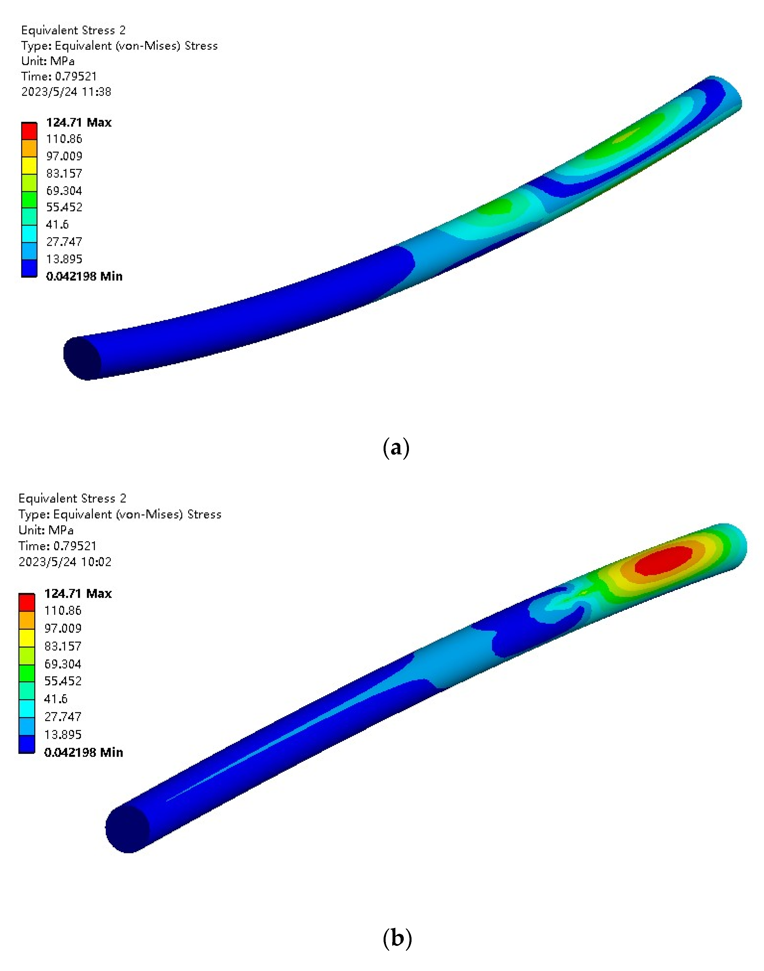
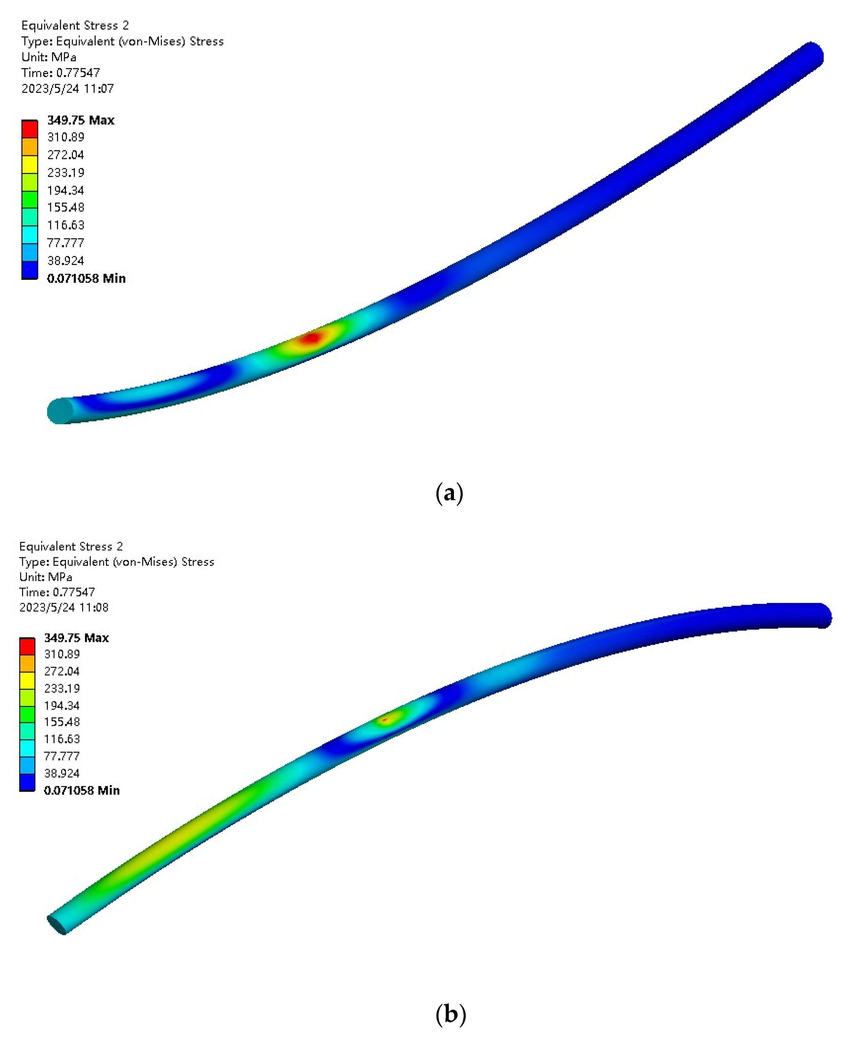
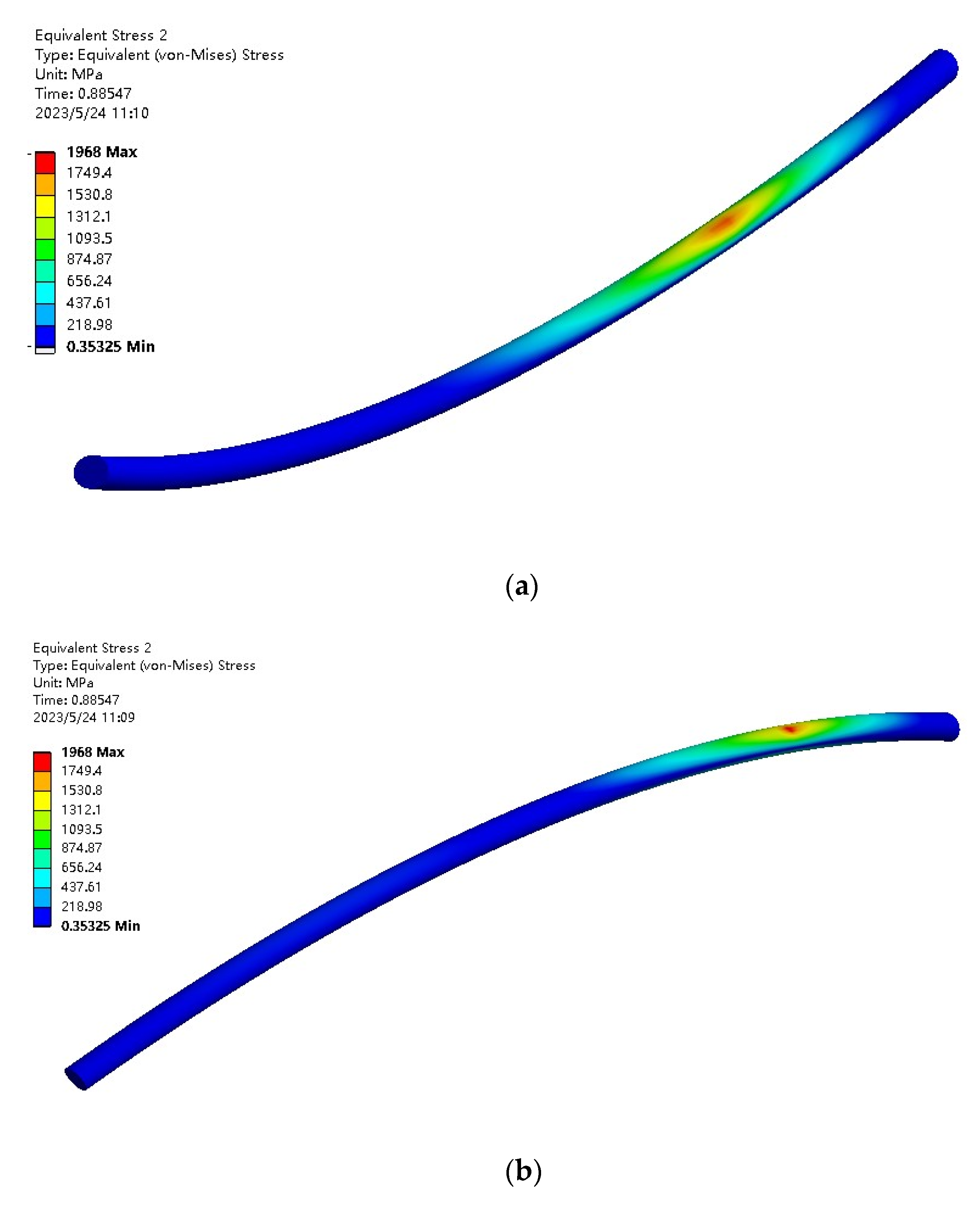
4.4. Simulation Results

The purpose of the finite element analysis of the submarine cable towing in this paper is to determine the location of the stress risk area during the submarine cable towing process. Therefore, before the simulation of the submarine cable towing, the towing process is simplified. The size was reduced by 100 times, and the gravity was increased by 100 times at the same time, keeping the towing force the same as the actual towing force of 1200 m, and then the whole towing process was divided into three stages, respectively reaching 1/8, 1/2, and the end of the cable entering the pipeline. At the endpoint, the three stages were simulated and analyzed, and the dangerous points of plastic deformation were observed by comparing the results.
  • The initial stage of cable towing
The finite element analysis was performed when the submarine cable entered the pipeline with the drag reaching 1/8. At this time, the length of the submarine cable entering the pipeline was about 150 m, and the drag force increased from 0 to 50 kN with time. When the time was 1 s, the stress cloud diagram of the submarine cable is shown in Figure 11.
It can be seen that the maximum stress value of the submarine cable was 217.31 MPa, which was located on the friction surface where the submarine cable contacted the pipeline and was in the first half of the entire submarine cable.
2.
Intermediate stage of submarine cable hauling
The finite element analysis was performed when the submarine cable entered the pipeline with the dragging to 1/2. At this time, the length of the submarine cable entering the pipeline was about 600 m, and the drag force setting value increased from 0 to 1460 kN.
In the first 0.25 s, the stress value of the submarine cable increased steadily and slowly with the increase of the tensile force, and the stress value of the submarine cable stabilized in a lower range between 0.25 s and 0.75 s. The ultimate stress of the submarine cable began to increase rapidly; the change node 0.80 s and the point of the maximum stress value 1.0 s were selected for observation. For this time, the stress cloud diagram of the submarine cable is shown in Figure 12 and Figure 13.
It can be seen that at 0.80 s, the maximum stress value of the submarine cable was 124.71 MPa, which was located on the friction surface where the submarine cable contacts the pipeline and was near the tension surface of the entire submarine cable. At 1.0 s, the maximum stress on the submarine cable was 866.74 MPa, which was located on the friction surface where the submarine cable contacted the pipeline, near the middle of the entire submarine cable.
3.
Submarine cable towing end stage
The finite element analysis was performed when the submarine cable entered the pipeline with the dragging and reached the endpoint. At this time, the length of the submarine cable entering the pipeline was about 1200 m, and the setting value of the drag force increased from 0 to 5000 kN. At 0.78 s, the maximum stress on the submarine cable is 349.75 MPa, which was located on the friction surface where the submarine cable was in contact with the pipeline, near the tension surface of the entire submarine cable. At 0.90 s, the maximum stress on the submarine cable was 1968 MPa, which was located on the friction surface where the submarine cable contacted the pipeline, near the rear section of the entire submarine cable. For this time, the stress cloud diagram of the submarine cable is shown in Figure 14 and Figure 15.
In general, when towing submarine cables, the internal stress of the cables demonstrates a process of change. When the towing force is small, the submarine cable is stationary, so the stress is small and stable. When the towing force gradually increases, just enough to make the whole submarine cable move, the submarine cable’s internal stress shows a rapid increase. When under the action of the towing force, the front section of the submarine cable is out of contact with the pipeline, and the area under the greatest force in this state is mostly the front end of the contact area between the submarine cable and the pipeline. In the whole process of submarine cable towing, combined with the position of the maximum stress point in the finite element simulation, it can be concluded that with the constant increase of towing force, the internal stress of submarine cable increases while the moving speed of submarine cable accelerates gradually. However, the area of maximum stress is still the front end of the real-time contact surface between the submarine cable and the pipeline.
Therefore, in the process of submarine cable towing, the area most prone to plastic deformation is the front end of the real-time contact surface between the submarine cable and the pipeline. The detection robot can refer to this result when it conducts the detection operation, and the front end of the contact area between the submarine cable and the pipeline during towing operations can be emphatically inspected.

5. Performance Experiment of Submarine Cable Outer Wall Detection Robot

The inspection robot will operate at an average seabed depth of 18 m under the seawater, however, the maximum depth of the seawater will not exceed 90 m, and the pressure of the seawater will not exceed 0.9 MPa. The robot’s own material strength is great enough that the impact from seawater pressure is negligible. The inspection robot records the change of submarine cable diameter in real time by detecting the change in the wheel clamp stress, so as to obtain the damage situation of the submarine cable. Therefore, the analysis and detection of the robot focus is on the performance and stability of the submarine cable walking.

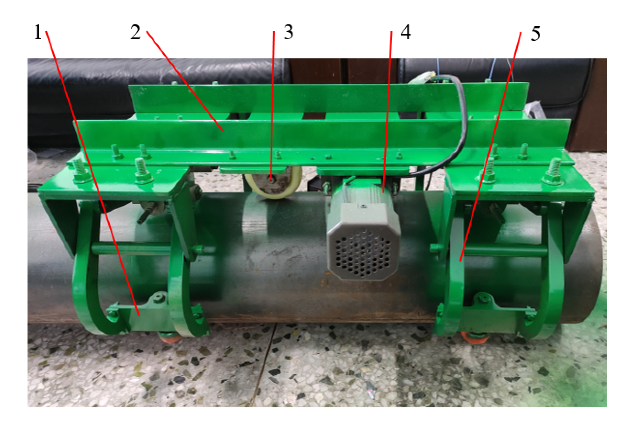
5.1. Experimental Device Structural Scheme

The experimental prototype of the submarine cable outer wall detection robot used was the first-generation prototype. The main design purpose was to test the actual motion performance of the detection robot and verify the working condition of the wheel arm module. The test results were used as a reference for the subsequent improvement of the detection robot. The structure and control scheme of the submarine cable outer wall detection robot were correspondingly simplified, and the clamping arm motor in the wheel arm module was replaced by manually rotating the lead screw. Finally, after each module was assembled, its physical prototype can be seen in Figure 16. The structure of the wheel clamp is driven by a screw-nut mechanism, which can realize a self-locking function. When no torque is provided for the drive screw, the screw-nut structure will self-lock. After the screw is turned to pre-tighten the wheel clamp, the wheel clamps will be firmly clamped on the outer wall of the submarine cable to provide a good grip on the wheel. The wheel clamps will be firmly clamped on the outer wall of the submarine cable to provide a good grip on the wheel.
The control system of the submarine cable outer wall detection robot experimental prototype is mainly composed of a PC terminal, an ARM controller, a film pressure sensor and its conversion module, a camera, an adjustment steering gear, a motor, and a governor [29]. Serial communication is carried out through the host computer and the ARM controller, the camera transmits video signals to the host computer through USB, the ARM controller reads the sensor data and controls the rotation of the steering gear, and the governor controls the forward and reverse rotation and speed of the motor. The actual connection of its hardware circuit is shown in Figure 17.

5.2. Experimental Process and Result Analysis

In the experiment of this paper, a steel pipe with an outer diameter of ϕ252 mm was used to replace the submarine cable, the experimental prototype was loaded on the pipe, and the pipe was clamped by adjusting the position of the wheel arm module, and the next experiment was carried out.
First, the walking experiment of the submarine cable outer wall detection robot was carried out, and the numerical change of the clamping force was measured and recorded, and the stability of the robot’s walking was detected by observation.
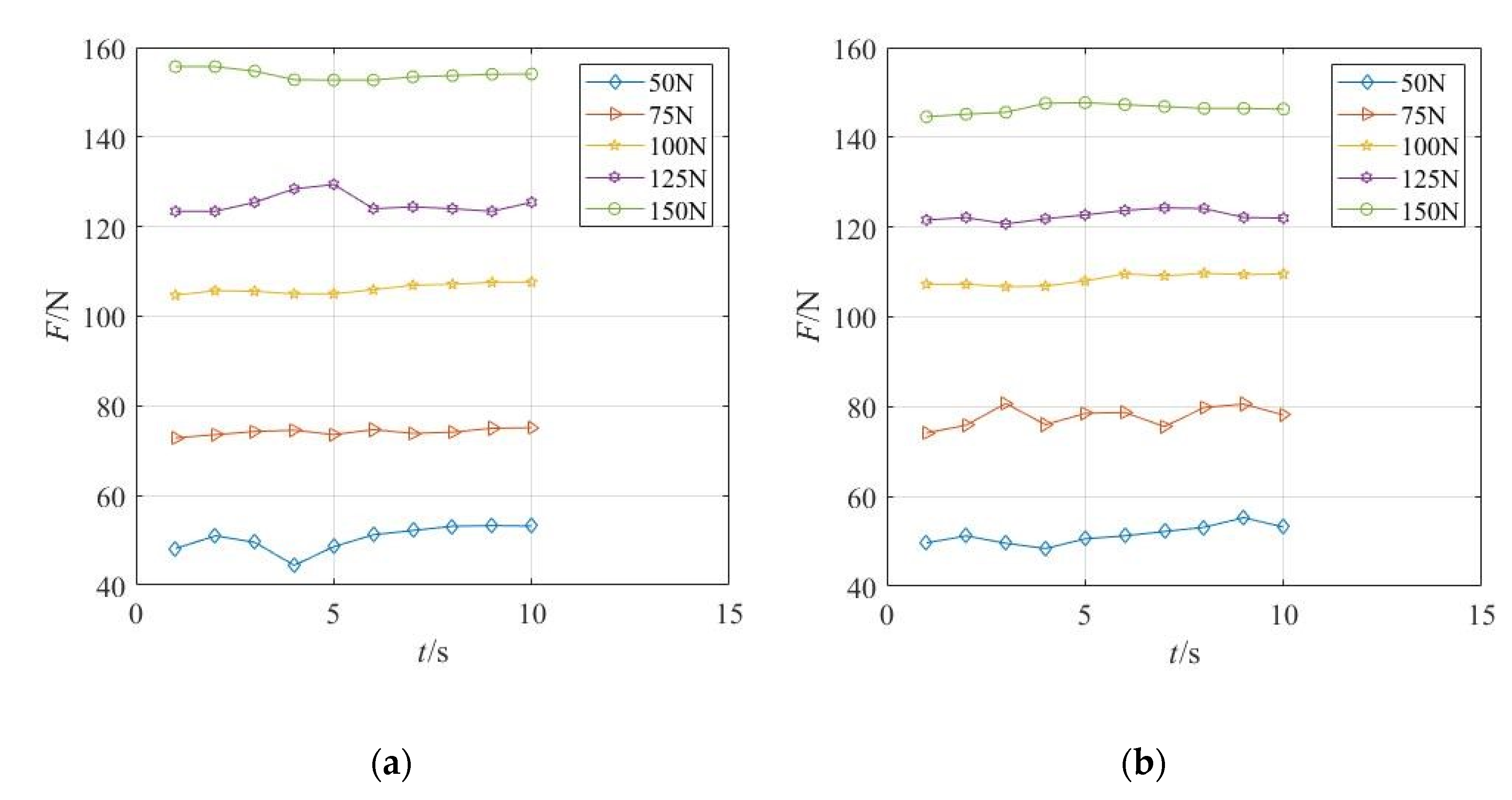
  • Walking experiments on horizontal pipes
We adjusted the preload force of the wheel arm module to 50 N, 75 N, 100 N, 125 N, and 150 N, respectively. After several measurements, the relationship between the average walking speed of the robot and the preload force is shown in Table 2. The change curve of the clamping force of the wheel arm module is shown in Figure 18.
During the horizontal movement, the robot was detected to walk stably, the preload force was 50~150 N, and the robot did not tilt significantly. Through the measurement, it was found that the deviation angle of the robot during the movement was within 2°.
2.
Walking experiments on inclined pipes
The actual submarine surface was an irregular steel external pipeline laying on the seabed and inevitably will have a tilt angle; its internal laying submarine cables will also tilt. In the experiment, a spacer block was used to raise one end of the pipeline and tilt it about 10°, as shown in Figure 19, which was used to simulate the situation of submarine cable tilting at the bottom of the sea. The tilt angle of 10° included all the tilt angles that may occur when the submarine cable is laid in the steel external pipeline in real working conditions. Then, the preload force of the wheel arm module was adjusted to 50 N, 75 N, 100 N, 125 N, and 150 N, respectively. After several measurements, the relationship between the average walking speed of the detection robot and the preload force is shown in Table 3. The change curve of the clamping force of the front and rear wheel arm modules of the detection robot is shown in Figure 20. It was found through observation that the clamping force was 50~150 N. The pose of the robot did not change much.
In the detection of the tilting motion of the robot, when the preload force was zero, the robot slid off the pipe. After the preload force was increased to 50 N, the sliding phenomenon did not appear again. At the same time, the walking was relatively stable, and there was no significant inclination.
It can be seen from the walking realization of the submarine cable outer wall detection robot that the operation of the detection robot was stable and reliable, and the speed could meet the design requirements. In general, the speed on the inclined pipe was slightly lower than that on the horizontal pipe movement, and the maximum speed was 15.15 m/min and 14.28 m/min, respectively, when the preload was 50 N in both motion conditions. By detecting the real-time change graph of the clamping force when the robot moves, it can be seen that the clamping force was stable near the preset value, indicating that the wheel arm module had a good self-locking performance.
Through the walking experiment of the inspection robot on the submarine cable, the experimental results prove that the inspection robot can judge the diameter change of the submarine cable by real-time monitoring of the stress change on the wheel clamp so as to obtain the damage situation of the submarine cable. Based on the finite element analysis results of the submarine cable above, the maximum stress area of the submarine cable was shown to determine the most likely deformation area. The inspection plan of the inspection robot was formulated comprehensively, and the area where the submarine cable receives the greatest stress was inspected emphatically.
Since the rotation angle of the lead screw is inconvenient to measure, the distance between the transmission nut axis and the center point of the lead screw is converted by measuring the distance between the transmission nut and the central support plate of the lead screw. In the experiment, the rubber holster was used on the pipe to simulate the change in the diameter of the submarine cable. In the experiment, four rubber holsters with different thicknesses of 1 mm, 2 mm, 5 mm, and 10 mm were prepared to simulate submarine cables of different diameters, as shown in Figure 21. In order to reduce the experimental error, the clamping force should be reloaded after each diameter change, and the clamping force should be the same for each loading.
First, the wheel arm modules were divided into head wheel arm modules and tail wheel arm modules according to their positions. Each wheel arm module had two left and right transmission nuts. For the distance measurement, X1, X2, X3, and X4 will be used instead for convenient recording. The measurement results are shown in Table 4.
Theoretically, the distance between the drive nut and the center support plate of the lead screw will change by 2 mm for one revolution of the lead screw. However, it can be seen from the table that due to the machining error and installation error, the actual position of some parts was too far from the theoretical one. The value of 2 mm was brought into the calculation, and the actual change value will be used instead of the theoretical value for the calculation. At the same time, since the X4 deviation exceeded 50%, this value was not used for the calculation.
In the experiment to measure the diameter of the submarine cable and the position of the transmission nut, in order to facilitate the measurement and adjustment, the submarine cable and the detection robot were placed vertically, and the specific implementation is shown in Figure 22. The measurement results are shown in Table 5.
Drawing a line graph and performing curve fitting results are shown in Figure 23. It can be seen that due to installation errors, measurement errors, and many other factors, the broken lines of X1 and X2 deviated greatly from the theoretical curve, and the broken line of X3 was different from the theoretical curve, although it is relatively close. Through the curve fitting of MATLAB, polynomial fitting was selected, the order was selected as 2, and the fitting curve of each group of data was obtained. It can be seen that this measurement method is theoretically feasible, but due to the actual installation accuracy of the detection robot and measurement errors, and other reasons, there were large errors. Therefore, in order to reduce the measurement error, it is necessary to improve the measurement accuracy and installation accuracy. The formula completes the solution for the diameter of the submarine cable.

6. Conclusions

  • In this paper, a detection robot that walks along the outer wall of the cable inside the submarine casing is designed. It adopts a non-enclosed four-link clamping mechanism and a wheel drive, which is well adapted to the working conditions of the submarine cable in the casing and runs stably. The driving force is strong, and the detection task can be well completed.
  • We analyzed the force of the submarine cable towing in the crossing project. The finite element simulation was used to simulate the towing of the submarine cable in the pipeline, and it was confirmed that the most likely location for plastic deformation was the real-time contact surface between the submarine cable and the pipeline.
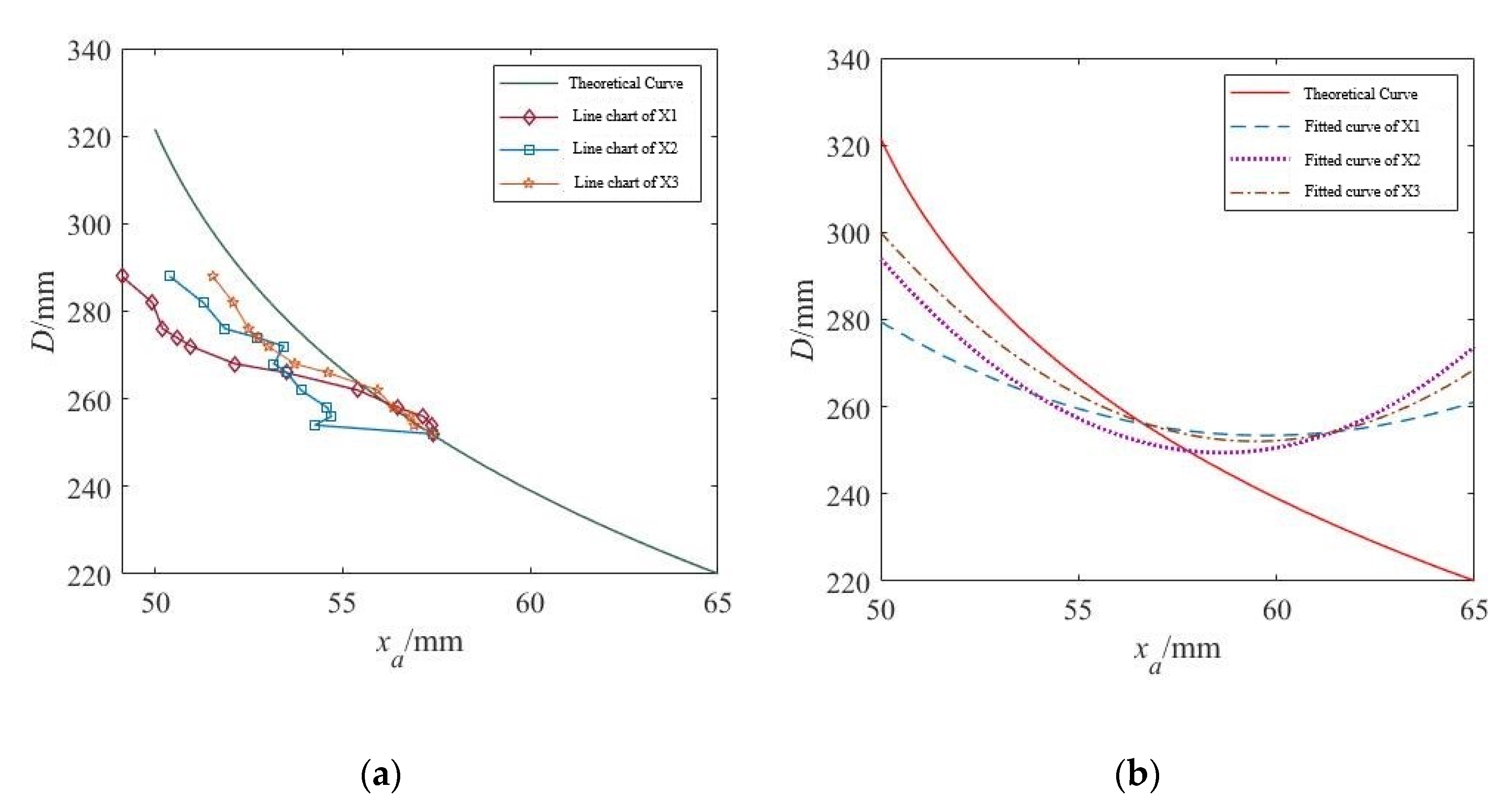
  • We carried out relevant experimental research on the detection robot of the outer wall of the submarine cable. The walking experiments were carried out on the horizontal and inclined pipelines, respectively. The experimental prototype reached the maximum running speed with a clamping force of 50 N, which were 15.15 m/min and 14.28 m/min, respectively. By measuring the relationship between the position of the wheel arm module parts and the change in the submarine cable diameter, the feasibility of measuring the change of cable diameter in real-time by the number of turns of the lead screw is proved.

Author Contributions

Conceptualization, Z.W. and B.Z.; methodology, Z.W.; software, Y.W.; validation, Y.W. and B.Z.; formal analysis, Z.W.; investigation, Y.W. and B.Z.; resources, B.Z.; data curation, Z.W.; writing—original draft preparation, Z.W.; writing—review and editing, Y.W.; visualization, Y.W.; supervision, Z.W. and B.Z.; project administration, B.Z.; funding acquisition, B.Z. All authors have read and agreed to the published version of the manuscript.

Funding

This paper was funded by NSFC (Contract name: Research on ultimate bearing capacity and parametric design for the grouted clamps strengthening the partially damaged structure of jacket pipes) (Grant No: 51879063). The views expressed here are the authors’ alone.

Institutional Review Board Statement

Not applicable.

Informed Consent Statement

Not applicable.

Data Availability Statement

Not applicable.

Conflicts of Interest

The authors declare no conflict of interest.

References

  1. Zhang, B.; Zhang, Q.R.; Wang, T.; Wang, Z. Research on the Bearing Capacity of a Damaged Jacket Repaired by a Grouting Clamp Based on a Type of Wedge Gripping. J. Mar. Sci. Eng. 2020, 8, 973. [Google Scholar] [CrossRef]
  2. Zhang, B.; Chen, H.; Wang, T.; Wang, Z. Design and Experiment of a Lifting Tool for Hoisting Offshore Single-Pile Foundations. Machines 2021, 9, 29. [Google Scholar] [CrossRef]
  3. Huang, P.Y.; Hua, X.L.; Hu, T.J.; Zhang, W.L.; Zhang, M.M.; Hu, H. Preliminary Conception of Submarine Cable and Pipeline Corridor Planning. Ocean. Dev. Manag. 2020, 37, 8–11. [Google Scholar]
  4. Zhou, X.; Jia, X.; Yin, G.Q. Research on sea-to-sea directional drilling crossing technology. Pipeline Technol. Equip. 2015, 3, 43–46. [Google Scholar] [CrossRef]
  5. Lin, R.R.; Du, N.F. A brief discussion on the application of offshore directional drilling traction pipes to cross submarine cables in submarine pipelines. China Water Transp. 2018, 18, 226–229. [Google Scholar]
  6. Alvi, M.J.; Izhar, T.; Qaiser, A.A.; Afzaal, M.U.; Anjum, A.; Safdar, A. Pliability assay of conventional gas insulated transmission line and flexible gas insulated transmission line regarding horizontal directional drilling based underground cable laying for metropolitan areas. In Proceedings of the 2018 IEEE International Conference on Environment and Electrical Engineering and 2018 IEEE Industrial and Commercial Power Systems Europe (EEEIC/I&CPS Europe) IEEE, Palermo, Italy, 12–15 June 2018. [Google Scholar] [CrossRef]
  7. Cho, K.H.; Kim, H.M.; Jin, Y.H.; Liu, F.; Moon, H.; Koo, J.C.; Choi, H.R. Inspection Robot for Hanger Cable of Suspension Bridge: Mechanism Design and Analysis. IEEE/ASME Trans. Mechatron. 2013, 18, 1665–1674. [Google Scholar] [CrossRef]
  8. Zhang, Z.H.; He, F.J. Design and analysis of an out-of-pipe crawling robot for row pipes. Mech. Transm. 2016, 40, 63–66. [Google Scholar] [CrossRef]
  9. Hans-Joachim, B. Grabenlose Auswechslung von Erdkabelleitungen. Acta Montan. Slovaca 2007, 12, 237–241. [Google Scholar]
  10. Wang, Z.Y. Structural Design and Adsorption Performance of Wind Turbine Tower Cleaning Robot; Harbin Engineering University: Harbin, China, 2016; pp. 30–35. [Google Scholar] [CrossRef]
  11. Almonacid, M.; Saltaren, R.; Aracil, R.; Reinoso, O. Motion planning of a climbing parallel robot. IEEE Trans. Robot. Autom. 2003, 19, 485–489. [Google Scholar] [CrossRef]
  12. Aracil, R.; Saltarén, R.; Reinoso, O. Parallel robots for autonomous climbing along tubular structures. Robot. Auton. Syst. 2003, 42, 125–134. [Google Scholar] [CrossRef]
  13. Aracil, R.; Saltaren, R.; Reinoso, O. A climbing parallel robot: A robot to climb along tubular and metallic structures. IEEE Robot. Autom. Mag. 2006, 13, 16–22. [Google Scholar] [CrossRef]
  14. Choi, C.; Park, B.; Jung, S. The Design and Analysis of a Feeder Pipe Inspection Robot With an Automatic Pipe Tracking System. IEEE/ASME Trans. Mechatron. 2010, 15, 736–745. [Google Scholar] [CrossRef]
  15. Noohi, E.; Mahdavi, S.S.; Baghani, A.; Ahmadabadi, M.N. Wheel-based climbing robot: Modeling and control. Adv. Robot. 2010, 24, 1313–1343. [Google Scholar] [CrossRef]
  16. Yuan, X.Q.; Ding, N.; Zhang, T.; Zhen, Z.L. Development of Portable Cable Robot. Mech. Des. Manuf. Eng. 2019, 48, 32–36. [Google Scholar] [CrossRef]
  17. Khan, M.B.; Chuthong, T.; Do, C.D.; Thor, M.; Billeschou, P.; Larsen, J.C.; Manoonpong, P. iCrawl: An Inchworm-Inspired Crawling Robot. IEEE Access 2020, 8, 200655–200668. [Google Scholar] [CrossRef]
  18. Ito, K.; Ninomiya, Y. TAOYAKA V: A multi-legged robot, successfully combining walking and climbing mechanisms. Artif. Life Robot. 2021, 26, 97–102. [Google Scholar] [CrossRef]
  19. Dutta, S.K.; Reddy, B.S.; Dwivedy, S.K. Complibot: A compliant external pipe climbing robot. Mech. Based Des. Struct. Mach. 2023, 2023, 1–30. [Google Scholar] [CrossRef]
  20. Kawasaki, H.; Murakami, S.; Kachi, H.; Ueki, S. Novel climbing method of pruning robot. In Proceedings of the 2008 SICE Annual Conference, Chofu, Japan, 20–22 August 2008; pp. 160–163. [Google Scholar] [CrossRef]
  21. Lee, S.H. Design of the out-pipe type pipe climbing robot. Int. J. Precis. Eng. Manuf. 2013, 14, 1559–1563. [Google Scholar] [CrossRef]
  22. Ho, H.-N.; Kim, K.-D.; Park, Y.-S.; Lee, J.-J. An efficient image-based damage detection for cable surface in cable-stayed bridges. Ndt E Int. 2013, 58, 18–23. [Google Scholar] [CrossRef]
  23. Zheng, M.; Yang, M.; Yuan, X.; Ding, N. A Light-Weight Wheel-Based Cable Inspection Climbing Robot: From Simulation to Reality. In Proceedings of the 2018 IEEE International Conference on Robotics and Biomimetics (ROBIO), Kuala Lumpur, Malaysia, 12–15 December 2018; pp. 1365–1370. [Google Scholar] [CrossRef]
  24. Gao, Z.Y.; Peng, L.M. The design of the robot body for the detection of the stay cables of the Hangzhou Bay Bridge. Shanxi Archit. 2012, 38, 174–175. [Google Scholar] [CrossRef]
  25. Md-Yusoff, M.N.S.; Bin Cheah, K.; Mohamad-Wazir, A.R.; Othman, W.A.F.W.; Alhady, S.S.N.; Wahab, A.A.A. Steel Pipe Climbing Robot Development. In Proceedings of the 11th International Conference on Robotics, Vision, Signal Processing and Power Applications, Lecture Notes in Electrical Engineering; Springer: Singapore, 2022; Volume 829. [Google Scholar] [CrossRef]
  26. Li, D.Q.; Wang, W.L.; Lin, Y.H.; Zhang, Z.S.; Zhang, X.L. Exploration and practice of land-to-sea directional drilling crossing technology in ocean engineering. J. Ocean. Technol. 2020, 39, 95–100. [Google Scholar]
  27. Yang, N. Tension Analysis of Submarine Cables during Laying Process; Shanghai Jiaotong University: Shanghai, China, 2015; pp. 40–58. [Google Scholar]
  28. Liu, X.; Ai, Z.J.; Li, H.Y.; Hu, K.; Yu, J.G. Calculation method of back drag force of horizontally oriented crossing stiffness winch. J. Wuhan Univ. 2018, 51, 356–362. [Google Scholar] [CrossRef]
  29. Salhaoui, M.; Molina-Molina, J.C.; Guerrero-González, A.; Arioua, M.; Ortiz, F.J. Autonomous Underwater Monitoring System for Detecting Life on the Seabed by Means of Computer Vision Cloud Services. Remote Sens. 2020, 12, 1981. [Google Scholar] [CrossRef]
Figure 1. Classification of mechanically clinging pipe-climbing robots: (a) shows the clinging pipe-climbing robot with wheel type, (b) shows the clinging pipe-climbing robot with track type, (c) shows the clinging pipe-climbing robot with foot type, (d) shows the clinging pipe-climbing robot with parallel mechanism type.
Machines 11 00627 g001
Figure 2. 3D simulation diagram of submarine cable in the external pipeline: (a) shows the axonometric view of submarine cable in the external pipeline, (b) shows the front view of submarine cable in the external pipeline. (1—submarine cable, 2—external pipeline).
Machines 11 00627 g002
Figure 3. The overall structure of the submarine cable outer wall detection robot (1—wheel arm module; 2—underwater electronic module; 3—profile frame; 4—driven wheel module; 5—driving wheel module).
Machines 11 00627 g003
Figure 4. Schematic diagram of the wheel arm module (1—clamping wheel; 2—clamping arm; 3—clamping arm pin; 4—clamping arm support; 5—connecting rod pin; 6—connecting rod; 7—lead screw; 8—drive nut; 9—support base plate; 10—encoder).
Machines 11 00627 g004
Figure 5. Submarine cable modeling analysis diagram: (a) shows the schematic diagram of submarine cable towing, (b) shows the force balance diagram of beam element.
Machines 11 00627 g005
Figure 6. Relationship between cable tension T(z), Lb, and angle θ.
Machines 11 00627 g006
Figure 7. Calculation model of resistance of submarine cable towing. α2 is the Angle between the axis of the submarine cable at the second node and the horizontal line. The nodes between the fourth node and the (i − 1)-th node are omitted from the figure.
Machines 11 00627 g007
Figure 8. Cross-sectional view of submarine cable.
Machines 11 00627 g008
Figure 9. Modeling of the armor layer.
Machines 11 00627 g009
Figure 10. Grid division diagram of submarine cable(1—copper conductor, 2—the outer protective layer of copper conductor, 3—other protective layers, 4—48-core single fiber optic cable).
Machines 11 00627 g010
Figure 11. Stress cloud diagram at the initial stage of 1 s: (a) shows the top view of the submarine cable, (b) shows the bottom view of the submarine cable.
Machines 11 00627 g011
Figure 12. Stress cloud diagram at 0.80 s in the middle stage: (a) shows the top view of the submarine cable, (b) shows the bottom view of the submarine cable.
Machines 11 00627 g012
Figure 13. Stress cloud diagram at the intermediate stage of 1 s: (a) shows the top view of the submarine cable, (b) shows the bottom view of the submarine cable.
Machines 11 00627 g013
Figure 14. Stress contour at the last stage of 0.78 s: (a) shows the top view of the submarine cable, (b) shows the bottom view of the submarine cable.
Machines 11 00627 g014
Figure 15. Stress cloud diagram at the last stage of 0.89 s: (a) shows the top view of the submarine cable, (b) shows the bottom view of the submarine cable.
Machines 11 00627 g015
Figure 16. Experimental prototype of the inspection robot (1–front wheel arm module; 2–profile frame; 3–driven wheel module; 4–driving wheel module; 5–rear wheel arm module).
Machines 11 00627 g016
Figure 17. Physical connection diagram of hardware circuit (1–film pressure sensor; 2–camera module; 3–upper computer; 4–control board; 5–speed regulating motor; 6–speed governor).
Machines 11 00627 g017
Figure 18. Variation of clamping force in horizontal movement with time: (a) shows the variation curve of clamping force of front wheel arm module with movement, (b) shows the variation curve of clamping force of rear wheel arm module with movement.
Machines 11 00627 g018
Figure 19. Schematic diagram of the inclined pipe walking experiment.
Machines 11 00627 g019
Figure 20. Variation of the clamping force with time in tilting motion: (a) shows the variation curve of clamping force of front wheel arm module with movement, (b) shows the variation curve of clamping force of rear wheel arm module with movement.
Machines 11 00627 g020
Figure 21. Physical map of rubber holster.
Machines 11 00627 g021
Figure 22. Schematic diagram of the position measurement of the wheel arm module.
Machines 11 00627 g022
Figure 23. The broken line graph of the wheel arm modules X1, X2, and X3, and their fitting curves: (a) shows the line graph of measurement results, (b) shows the curve fitting diagtam of measurement results.
Machines 11 00627 g023
Table 1. HYJQF41-F-127/220 kV cable structure parameters.
NoCompositionNominal ThicknessReference Outside Diameter (mm)
1Copper conductor + water-blocking tape/29.9
2Conductor shield233.9
3XLPE insulation2685.9
4Insulation shield1.288.3
5Semiconducting resistance hose0.890.7
6Lead sheath3.697.9
7PE sheath3.3105.5
8padding/227.2
948-core single fiber optic cable//
10Rubberized cloth bag0.3229
11PP rope1.5232
12Galvanized steel wire6244
13PP outer cover4252
Table 2. Relationship between average walking speed and preload.
Preload force
(N)
5075100125150
Average speed
(m/min)
15.1812.6313.2313.4712.81
Table 3. The relationship between the average walking speed and the preload in the tilting motion.
Preload force
(N)
5075100125150
Average speed
(m/min)
14.2813.1312.4313.1813.25
Table 4. The number of revolutions of the lead screw and the distance from the drive nut.
Number of TurnsHead Wheel Arm ModuleTail Wheel Arm Module
X1 (mm)X2 (mm)X3 (mm)X4 (mm)
130.0238.4738.7132.38
232.0640.3140.5534.73
334.0542.3342.4136.65
435.9044.2845.0242.34
537.8546.4546.3045.05
639.9448.2347.6547.50
Average value of Xi change per revolution1.981.951.793.02
Table 5. The distance between the cable diameter and the transmission nut when the clamping force is 100 N (mm).
DHead Wheel Arm ModuleTail Wheel Arm Module
X1Distance from the Center of the ScrewX2Distance from the Center of the ScrewX3Distance from the Center of the Screw
25246.5063.5043.5862.5841.9158.91
25446.4963.4942.4459.4441.4158.41
25646.2563.2542.8859.8841.3158.31
25845.5762.5742.7759.7740.8657.86
26244.5061.5042.0759.0740.4457.44
26642.5959.5941.6958.6939.1156.11
26841.2358.2341.3558.3538.2355.23
27240.0657.0641.6158.6137.5354.53
27439.6856.6840.9057.9037.2554.25
27639.3056.3040.0557.0537.0054.00
28239.0356.0339.4656.4636.5953.59
28838.2155.2139.5755.5736.0553.05
Disclaimer/Publisher’s Note: The statements, opinions and data contained in all publications are solely those of the individual author(s) and contributor(s) and not of MDPI and/or the editor(s). MDPI and/or the editor(s) disclaim responsibility for any injury to people or property resulting from any ideas, methods, instructions or products referred to in the content.

