

Study on Fatigue Characteristics of Rivets in Bearing Cage for an Aeroengine Transmission System


Abstract
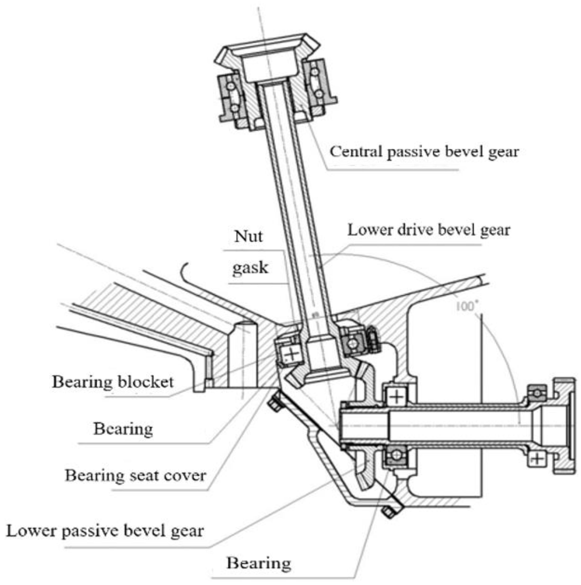
:1. Introduction
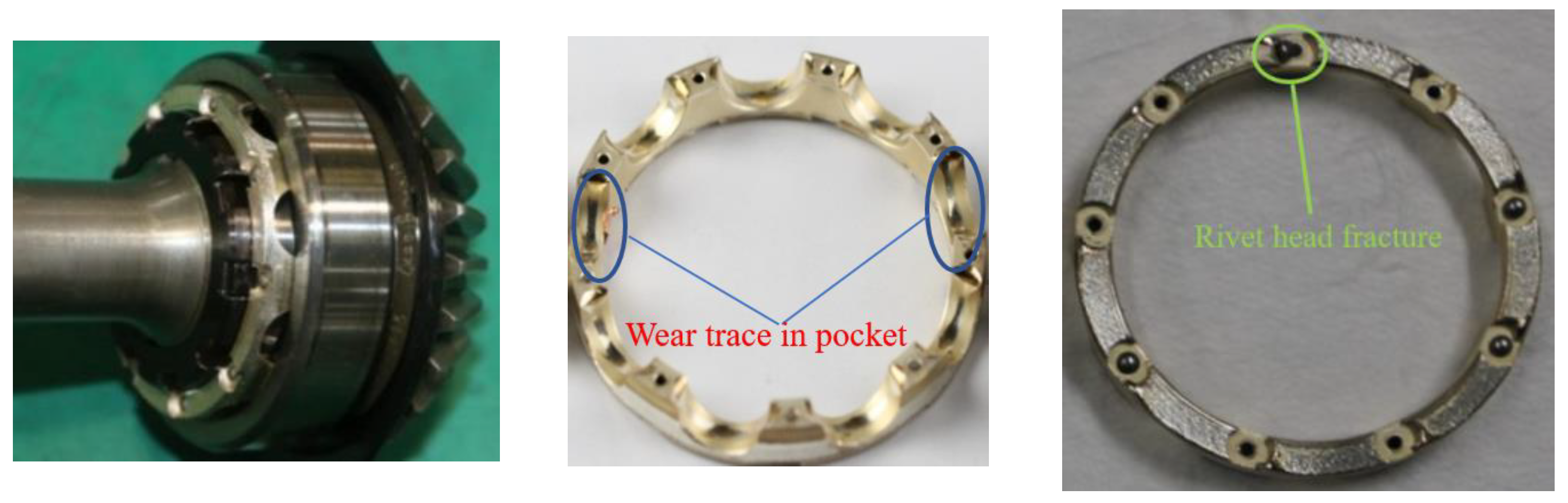
2. Early Fracture Failure Characterization of the Rivets and Cage
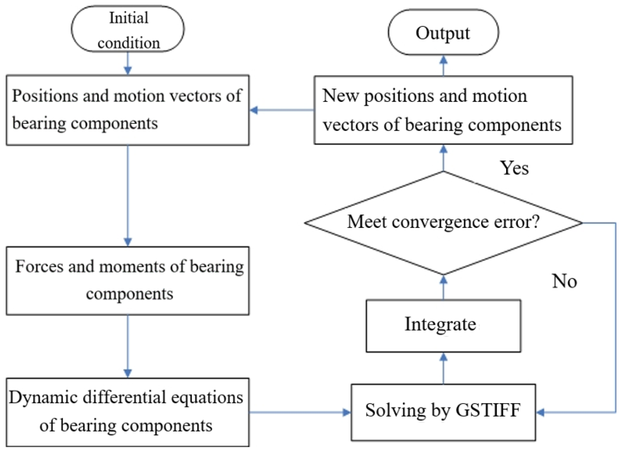
3. Dynamic Analysis Model of a Ball Bearing
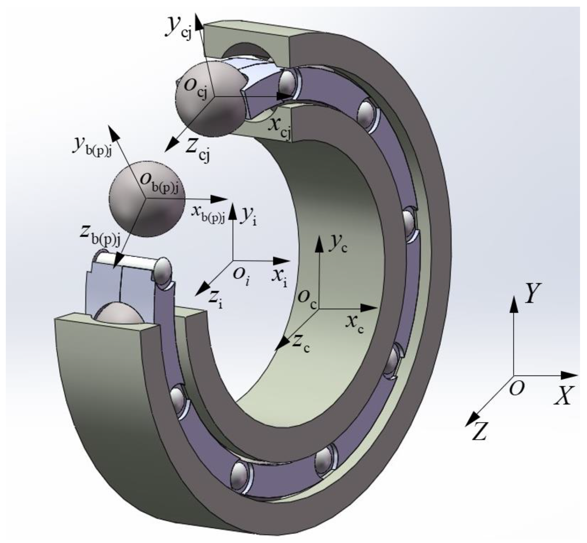
3.1. Define the Coordinate System
- (1)
- The inertial coordinate system {O; X, Y, Z} is fixed in space, the origin coincides with the bearing center, the X axis coincides with the bearing axis, and the YOZ plane is parallel to the radial plane through the bearing center.
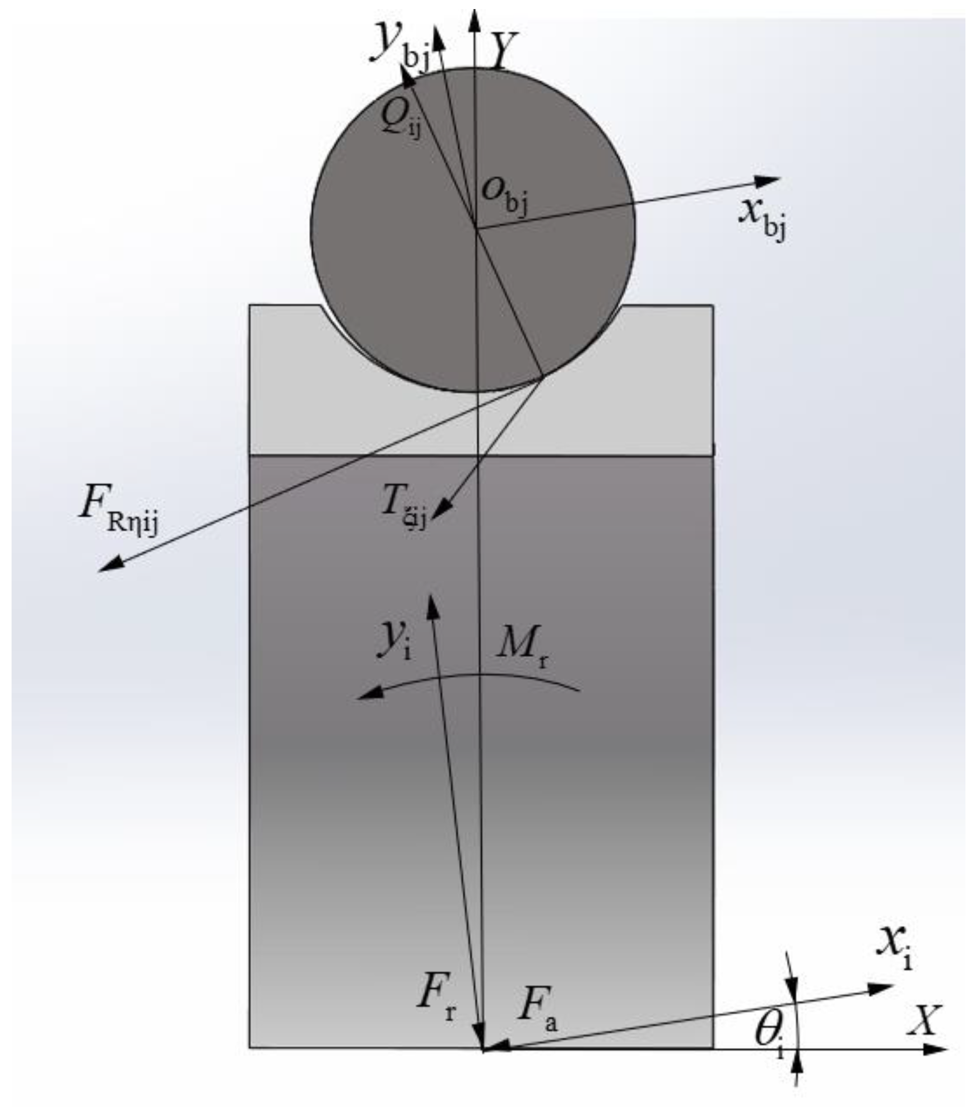
- (2)
- The inner ring coordinate system {oi; xi, yi, zi} is fixed with the inner ring, the origin coincides with the inner ring mass center, the xi axis coincides with the inner ring rotation axis, and the yioizi plane coincides with the inner ring radial plane through the inner ring mass center.
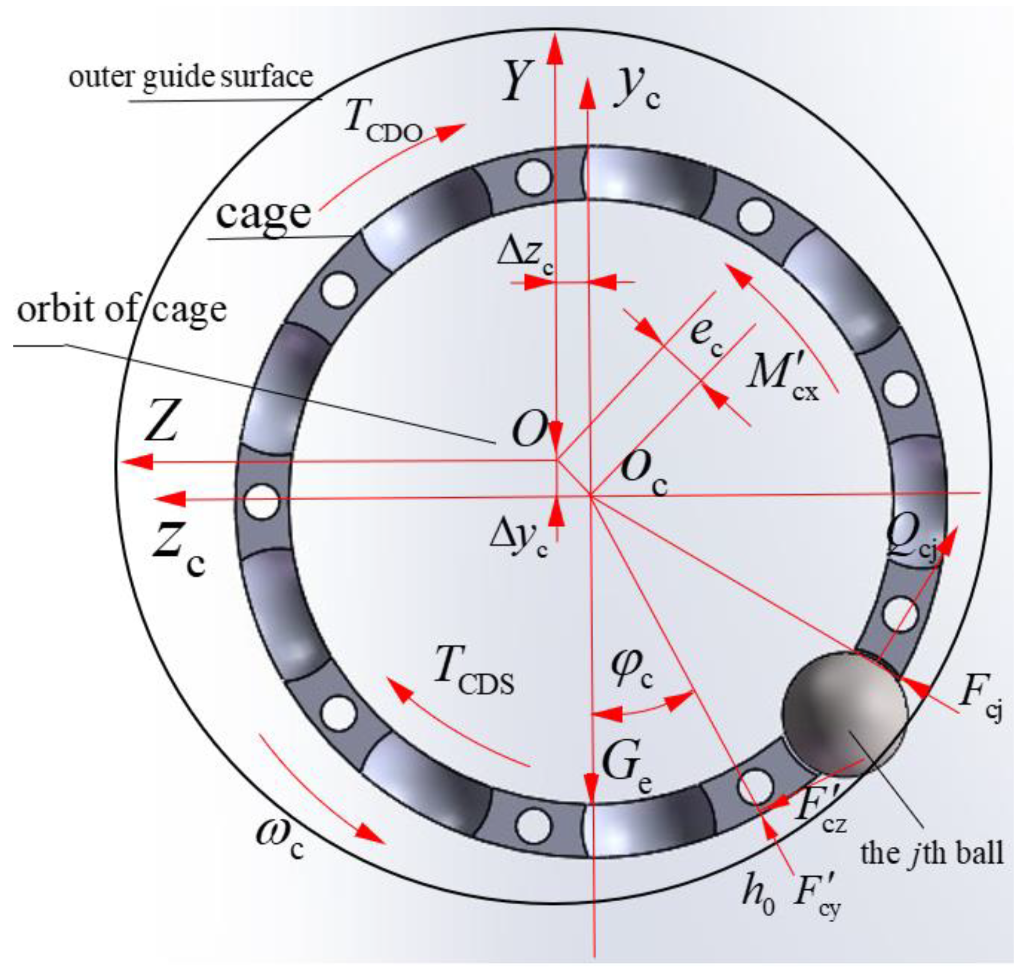
- (3)
- The cage coordinate system {oc; xc, yc, zc} is fixed with the cage, the origin coincides with the cage mass center, the xc axis coincides with the cage rotation axis, and the ycoczc plane coincides with the cage radial plane through the cage mass center.
- (4)
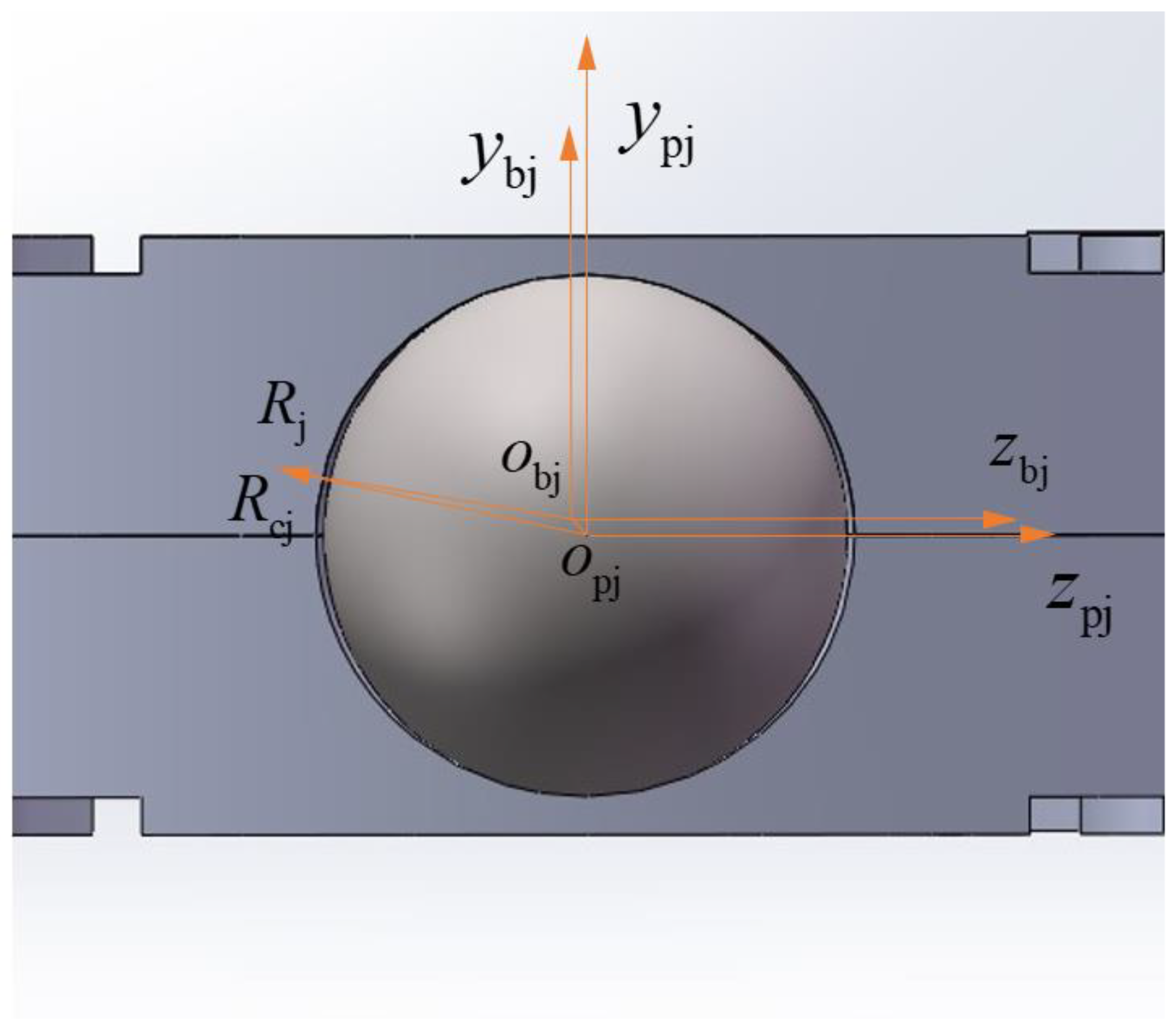
- The coordinate system of the cage pocket center {opj; xpj, ypj, zpj} is fixed in the jth cage pocket center and it moves with the cage; the origin opj coincides with the cage pocket geometric center, ypj is along the radial direction of the bearing, zpj is along the circumference direction of the bearing, xpj is determined by ypj and zpj according to the right-hand rule, and each cage pocket has its own local coordinate system.
- (5)
- The coordinate system of the jth ball {obj; xbj, ybj, zbj} is fixed in the jth ball mass center and it moves with the ball; the origin obj coincides with the ball mass center, ybj is along the radial direction of the bearing, zbj is along the circumference direction of the bearing, xbj is determined by ybj and zbj according to the right-hand rule, and each ball has its own local coordinate system.
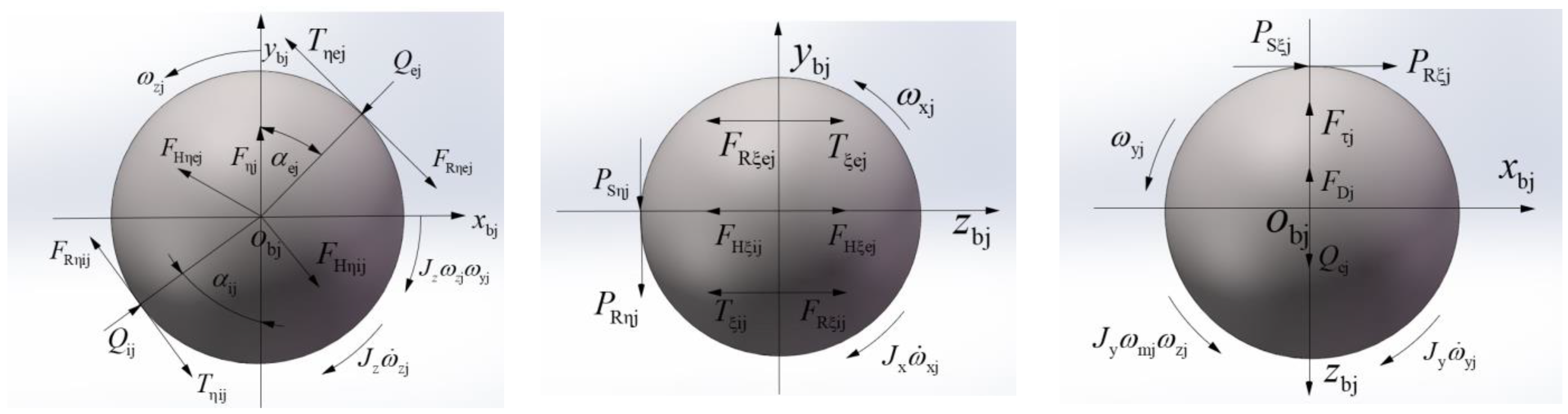
3.2. Nonlinear Dynamic Differential Equations of a Ball
3.3. Nonlinear Dynamic Differential Equations of the Cage
3.4. Nonlinear Dynamic Differential Equations of the Inner Ring
4. Results and Discussion
4.1. Analysis of the Rivet Stress
- (1)
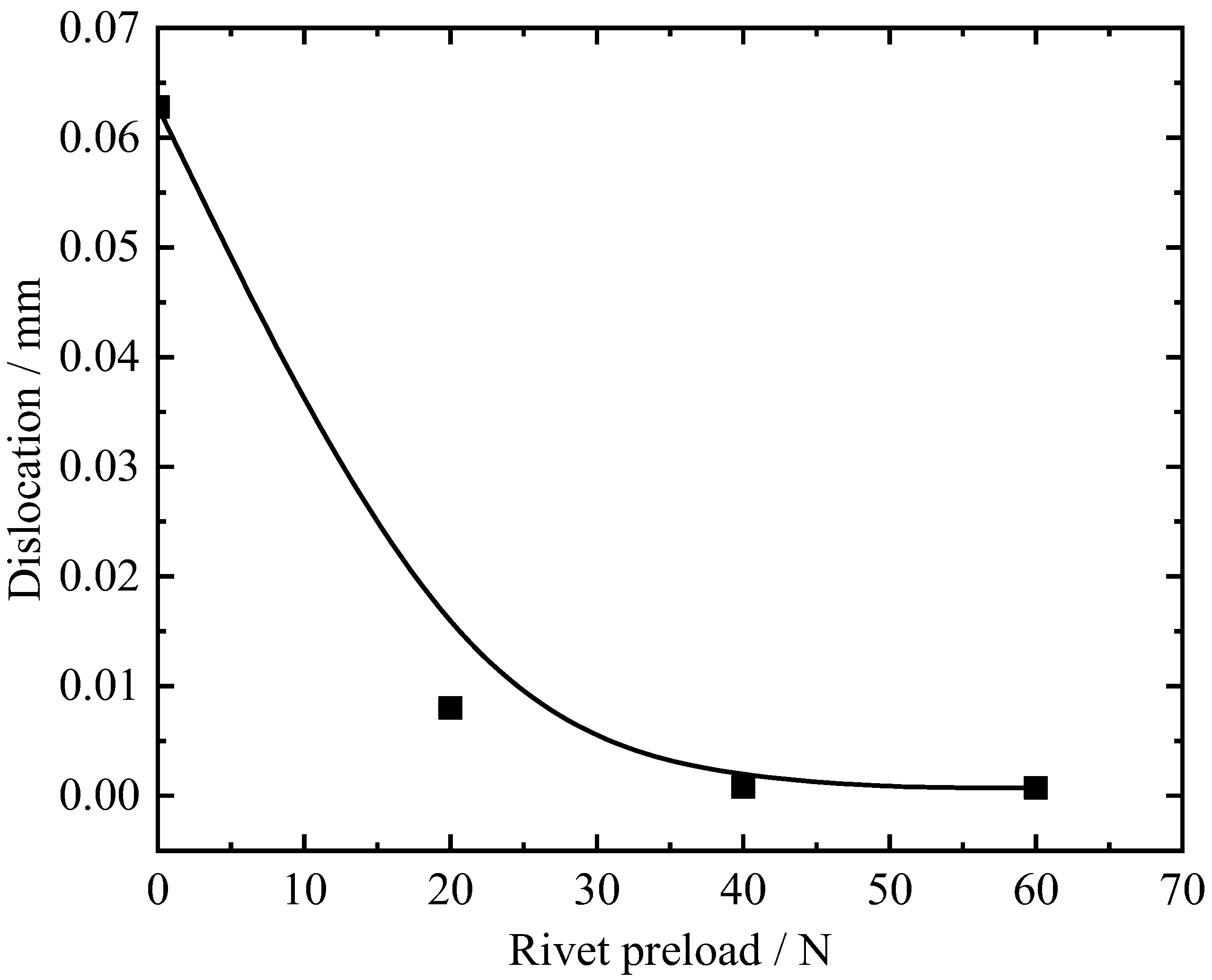
- Effect of the rivet preload on rivet stress
- (2)
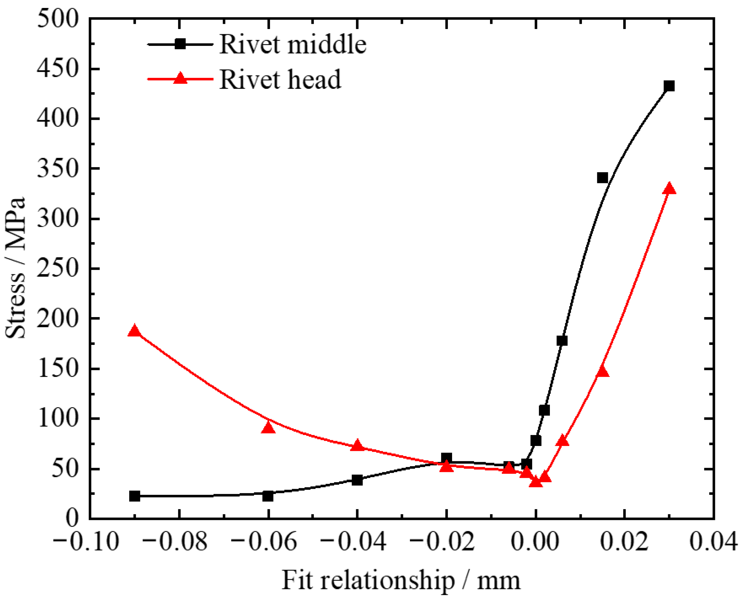
- Effect of the fit relationship between the rivet and the rivet hole on the rivet stress
- (3)
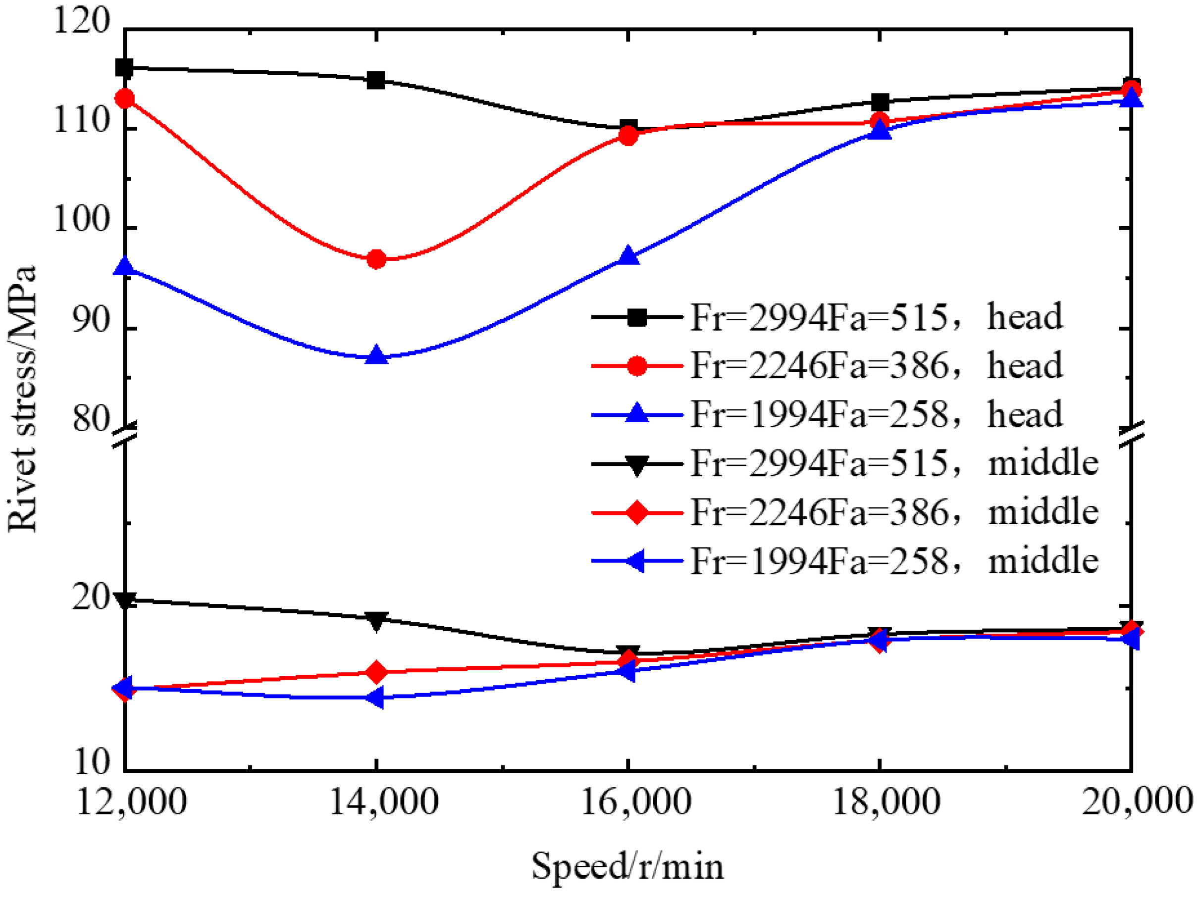
- Effect of the working conditions on the rivet stress
- (4)
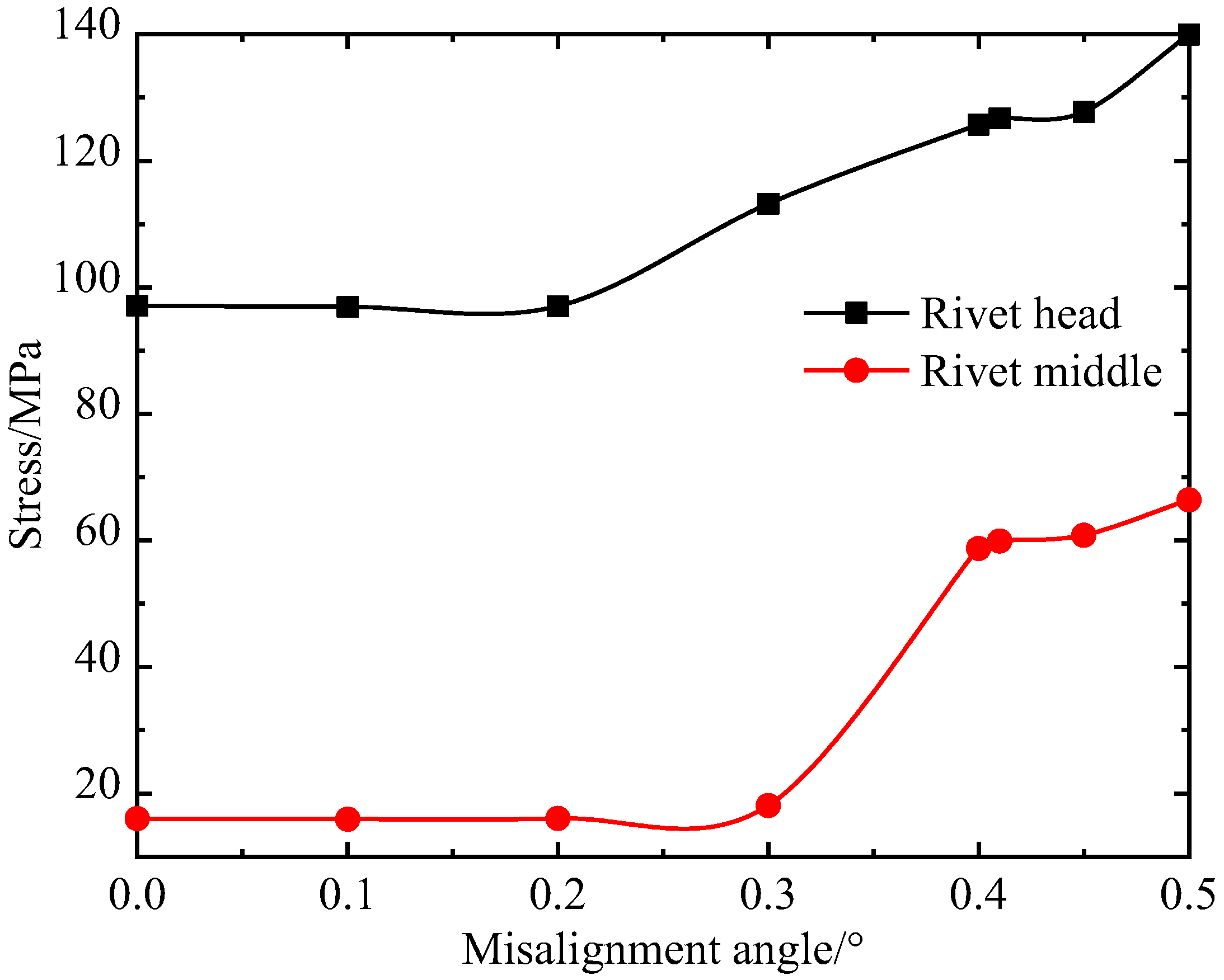
- Effect of the misalignment on the rivet stress
- (5)
- Effect of the cage clearance ratio on the rivet stress
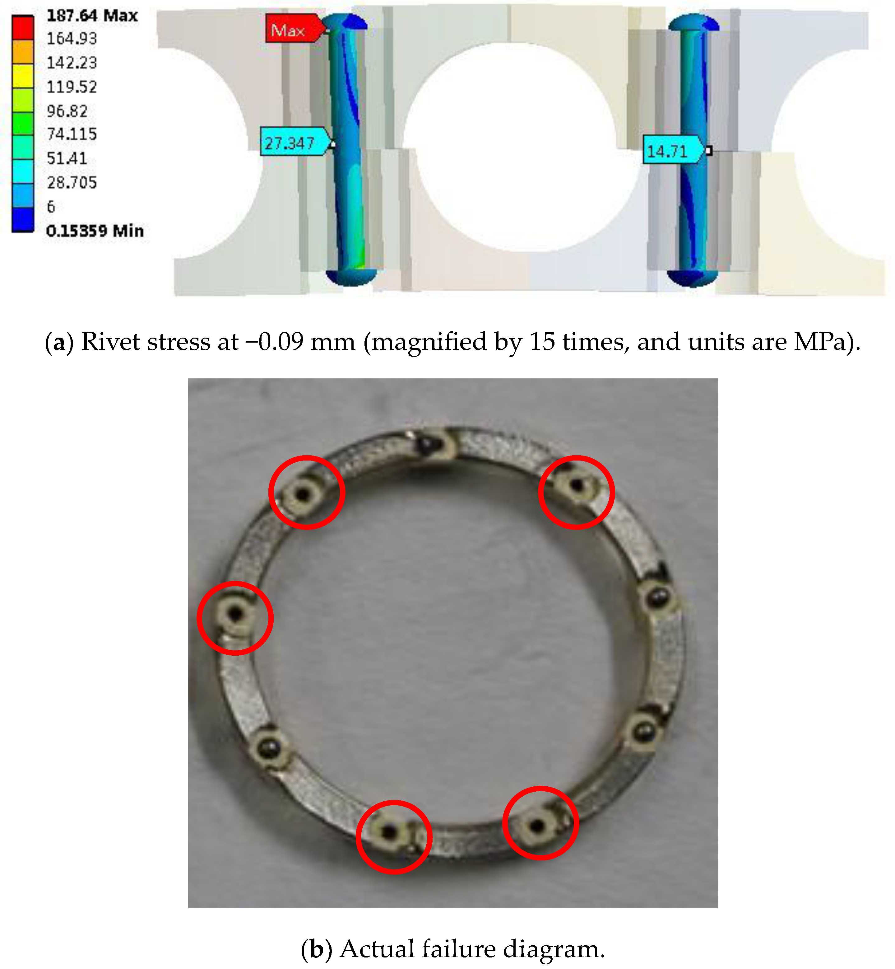
4.2. Comparison Validation
5. Conclusions
- (1)
- By delivering an optimal preload of the rivet, this causes the two halves of the cage to have less misalignment and a lower rivet stress. As the preload increases, the rivet stress increases. In addition, an excessive preload causes the rivet head to produce a great stress concentration. For the bearing studied in this investigation, the optimal preload of the rivet is 20 N–40 N.
- (2)
- The fit relationship between the rivet and the rivet bore has a significant influence on the rivet stress. There is an excessive stress on the rivet head when the fit clearance is too large, which causes the rivet head to break off. When the interference is large, the stress in the middle of the rivet rod is too large, which leads to the premature fatigue fracture in the middle of the rivet rod. For the 1.5 mm diameter rivet, we analyzed the appropriate fit relationship, which is −0.02 mm–0 mm.
- (3)
- The rivet stress increases with the bearing load increases. A reasonable matching value of the load and speed can reduce the rivet stress. The impact load acting on the bearing causes the rivet stress to increase. The rivet stress increases with an increase in the misalignment, and it increases sharply when the misalignment exceeds one threshold. The clearance ratio is close to 1, which is beneficial to reducing the rivet stress and increasing the cage fatigue life.
Author Contributions
Funding
Data Availability Statement
Conflicts of Interest
References
- Crawford, T.S. The experimental determination of ball bearing cage stress. Wear 1970, 16, 43–52. [Google Scholar] [CrossRef]
- Fang, N.; Pugh, D.; Themudo, R. On the stress concentration factors of rolling element bearing cages. Tribol. Trans. 2007, 50, 445–452. [Google Scholar] [CrossRef]
- Sakaguchi, T.; Harada, K. Dynamic analysis of cage stress in tapered roller bearings using component-mode-synthesis method. J. Tribol. 2009, 131, 01102. [Google Scholar] [CrossRef]
- Sakaguchi, T. Dynamic analysis for needle roller bearings under planetary motion. NTN Tech. Rev. 2007, 75, 94–99. [Google Scholar]
- Weinzapfel, N.; Sadeghi, F. A discrete element approach for modeling cage flexibility in ball bearing dynamics simulations. J. Tribol. 2009, 131, 02110. [Google Scholar] [CrossRef]
- Ashtekar, A.; Sadeghi, F. A new approach for including cage flexibility in dynamic bearing models by using combined explicit finite and discrete element methods. J. Tribol. 2012, 134, 041502. [Google Scholar] [CrossRef]
- Yang, H.-S.; Chen, G.-D.; Deng, S.-E.; Li, S. Rigid-flexible coupled dynamic simulation of aeroengine main-shaft high speed cylindrical roller bearing. In Proceedings of the 2010 3rd International Conference on Advanced Computer Theory and Engineering (ICACTE), Chengdu, China, 20–22 August 2010; Volume 4, pp. 31–35. [Google Scholar]
- Cui, Y.C.; Deng, S.E.; Ni, Y.G.; Chen, G. Effect of roller dynamic unbalance on cage stress of high-speed cylindrical roller bearing. Ind. Lubr. Tribol. 2018, 70, 1580–1589. [Google Scholar] [CrossRef]
- Li, H.T.; Zhang, W.H.; Deng, S.E.; Zheng, Y. Study on cage stress of cylindrical roller bearing at stop stage. Mech. Sci. Technol. Aerosp. Eng. 2018, 37, 172–179. (In Chinese) [Google Scholar]
- Huang, Y.S.; Deng, S.E.; Zhang, W.H. Influence of impact loads on the dynamic characteristics of plastic cages in railway axle bearings. J. Vib. Shock. 2018, 37, 172–180. (In Chinese) [Google Scholar]
- He, Z.G.; Liu, R.S.; Wang, X.H. Improvement of rivets for cage with cylindrical roller bearings. Bearing 2005, 7, 41. (In Chinese) [Google Scholar]
- Zhao, L.R.; Zhang, S.L. Analyzing deep groove ball bearing cage rivet for fracture reason. J. Harbin Bear. 2007, 28, 5–6. (In Chinese) [Google Scholar]
- He, X.G.; Liang, Y.; Song, H.T.; Guo, S. Failure analysis of rivets in bearing cage. Bearing 2012, 10, 37–39. (In Chinese) [Google Scholar]
- Qin, J.C.; Zhou, X.S. Failure analysis of rivets in bearing cage of DF 11g locomotive axle box. Locomot. Roll. Stock. Technol. 2009, 3, 45–46. (In Chinese) [Google Scholar]
- Li, Y.L.; Tao, C.H.; Zhang, W.F.; Jiang, T. Fracture analysis on cage rivets of a cylindrical roller bearing. Eng. Fail. Anal. 2008, 15, 796–801. [Google Scholar] [CrossRef]
- He, X.T.; Ye, X.N. Analysis of rivet heads shedding off from bearings maintainer of aero-engine. Fail. Anal. Prev. 2013, 8, 55–59. (In Chinese) [Google Scholar]
- Gu, C.M.; Gao, Y.; Ma, J. Analysis on riveting quality of cage of deep groove ball bearing. J. Harbin Bear. 2014, 35, 49–51. (In Chinese) [Google Scholar]
- Wang, S.T.; Gao, L.; Lu, Z.K. Analysis on cage fracture of a deep groove ball bearing. J. Harbin Bear. 2014, 35, 32–33,38. (In Chinese) [Google Scholar]
- Murashkina, V.V.; Klebanovb, Y.M.; Danilchenkoc, A.I.; Adeyanov, I.E. Loads and stress-strain state of gas turbine engine bearing cages. Russ. Aeronaut. 2017, 60, 658–661. [Google Scholar] [CrossRef]
- Zheng, B.; Yu, H.D.; Lai, X.M.; Lin, Z. Analysis of residual stresses induced by riveting process and fatigue life prediction. J. Aircr. 2016, 53, 1431–1438. [Google Scholar] [CrossRef]
- Huang, L.; Moraes, J.F.C.; Sediako, D.G.; Jordon, J.B.; Guo, H.; Su, X. Finite-element and residual stress analysis of self-pierce riveting in dissimilar metal sheets. J. Manuf. Sci. Eng. Trans. ASME 2017, 139, 021007. [Google Scholar] [CrossRef]
- Jin, K.; Wang, H.; Tao, J.; Tian, J. Effect of the interference fit on the stress distribution and failure mode of a flat-head riveted glare joint. Compos. Struct. 2020, 235, 111788. [Google Scholar] [CrossRef]
- Yongcun, C. Investigate the Performances of High-Speed Cylindrical Roller Bearing Based on Bearing Elements’ Dynamic Unbalance; Northwestern Polytechnical University: Xi’an, China, 2019. [Google Scholar]


| Item | Value |
|---|---|
| Bearing bore diameter (mm) | 35 |
| Bearing outer diameter (mm) | 72 |
| Bearing width (mm) | 17 |
| Ball diameter (mm) | 11.1125 |
| Ball number | 9 |
| Cage outer diameter (mm) | 59.5 |
| Cage bore diameter (mm) | 49.7 |
| Rivet diameter (mm) | 1.5 + 0.02/−0.04 |
| Rivet material | 15CrMn |
| Rivet material’s Young’s modulus (Gpa) | 192 |
| Rivet material’s density (g/cm3) | 7.82 |
| Rivet bore size (mm) | 1.5 + 0.05/−0.02 |
| Item | Value |
|---|---|
| Working load combinations (N) | Fr2994, Fa515; Fr2246, Fa386; Fr1994, Fa258 |
| Working bearing speed (r/min) | 18,238 |
Disclaimer/Publisher’s Note: The statements, opinions and data contained in all publications are solely those of the individual author(s) and contributor(s) and not of MDPI and/or the editor(s). MDPI and/or the editor(s) disclaim responsibility for any injury to people or property resulting from any ideas, methods, instructions or products referred to in the content. |
© 2023 by the authors. Licensee MDPI, Basel, Switzerland. This article is an open access article distributed under the terms and conditions of the Creative Commons Attribution (CC BY) license (https://creativecommons.org/licenses/by/4.0/).
Share and Cite
Cui, Y.; Cai, L.; Zhang, S.; Cui, Y.; Deng, S. Study on Fatigue Characteristics of Rivets in Bearing Cage for an Aeroengine Transmission System. Machines 2023, 11, 700. https://doi.org/10.3390/machines11070700
Cui Y, Cai L, Zhang S, Cui Y, Deng S. Study on Fatigue Characteristics of Rivets in Bearing Cage for an Aeroengine Transmission System. Machines. 2023; 11(7):700. https://doi.org/10.3390/machines11070700
Chicago/Turabian StyleCui, Yongcun, Linshen Cai, Song Zhang, Yufei Cui, and Sier Deng. 2023. "Study on Fatigue Characteristics of Rivets in Bearing Cage for an Aeroengine Transmission System" Machines 11, no. 7: 700. https://doi.org/10.3390/machines11070700
APA StyleCui, Y., Cai, L., Zhang, S., Cui, Y., & Deng, S. (2023). Study on Fatigue Characteristics of Rivets in Bearing Cage for an Aeroengine Transmission System. Machines, 11(7), 700. https://doi.org/10.3390/machines11070700