Article

Development of a Digital Twin for a Hydraulic, Active Seat Suspension System

by
Michele Gabrio Antonelli
1,
Jacopo Brunetti
1,
Walter D’Ambrogio
1,*,
Annalisa Fregolent
2 and
Pietro Nataletti
3
1
DIIIE—Dipartimento di Ingegneria Industriale e dell’Informazione e di Economia, Università degli Studi dell’Aquila, Piazzale Pontieri, Monteluco di Roio, I-67100 L’Aquila, Italy
2
DIMA—Dipartimento di Ingegneria Meccanica e Aerospaziale, Università di Roma La Sapienza, Via Eudossiana 18, I-00184 Roma, Italy
3
DiMEILA—Dipartimento di Medicina, Epidemiologia, Igiene del Lavoro e Ambientale, INAIL—Istituto Nazionale per L’Assicurazione Contro gli Infortuni sul Lavoro, Via Fontana Candida 1, I-00078 Monte Porzio Catone, Italy
*
Author to whom correspondence should be addressed.
Machines 2023, 11(7), 708; https://doi.org/10.3390/machines11070708
Submission received: 22 May 2023 / Revised: 27 June 2023 / Accepted: 28 June 2023 / Published: 3 July 2023
(This article belongs to the Section Robotics, Mechatronics and Intelligent Machines)

Abstract

:
The vibrations induced by the soil irregularities and other equivalent disturbances on agricultural tractors represent a major cause of disease for tractor drivers. The reduction of vibration exposure of operators is a topic of interest for the (Italian) National Institute for Insurance against Accidents at Work (INAIL). Several passive, semi-active, and active solutions are commercially available for the seat or the cabin suspension to isolate the driver from the vibrations. A prototype of a hydraulic active suspension system for the operator seat has been developed in the laboratories of INAIL. In this paper, nonlinear multi-physics modeling of the prototype has been carried after an experimental identification of the actuation system and specifically of the control valve parameters. The model is adjusted to retrace the system’s response and is used as a digital twin of the physical prototype to develop and optimize the control system. An equivalent simplified model is obtained to design a proper control strategy for the active suspension system. Finally, the controller is tested on the digital twin of the system to assess its performance in isolating vibrations.

1. Introduction

Vertical vibrations on agricultural tractors due to soil irregularities represent a major cause of occupational diseases or musculoskeletal disorders for agricultural operators. The control of noise and vibration on the operator is of interest to the (Italian) National Institute for Insurance against Accidents at Work (INAIL). A broad amount of literature exists on the effects of whole-body vibration exposure on operators of industrial and agricultural machines [1,2,3,4,5,6] and on seat suspension systems for agricultural tractors and off-road vehicles [7,8,9]. Several seat or cabin suspension systems are commercially available to reduce transmitted vibrations, including passive, semi-active, or active solutions. According to ISO 2631 [10], the frequency band of interest for the whole-body vibration ranges from 0.5 to 80 Hz. In this frequency range, acceleration is frequency weighted, and larger weights occur between 2 and 25 Hz (weights larger than 0.5). However, the vibration due to soil irregularities is low-pass mechanically filtered by the primary tractor suspension [11] and by the seat cushion [12], yielding a significant frequency content below 10 Hz. This is confirmed by Appendix 3 of Annex XIV of the European Regulation [13] regarding general requirements for the approval of agricultural and forestry vehicles.
Passive solutions are typically mechanical [14,15] or pneumatic [16] and generally allow for an attenuation of the vibrations beyond a given cut-off frequency or at a specific frequency. Semi-active solutions typically adjust the damping coefficient to adapt the system’s response to the excitation due to soil irregularities. The technologies commonly employed [17] are servo/solenoid valve dampers, magneto-rheological and electro-rheological dampers and electromagnetic dampers. Semi-active solutions based on pneumatic technology (e.g., multi-chamber devices) typically adjust the stiffness [18]. They guarantee better performances than passive isolation systems but typically require sensors and an electronic control unit. Active solutions are characterized by an actuation system based on hydraulic, direct-drive electromagnetic, electromagnetic hydrostatic, or geared electric motor technology [19,20,21,22].
A prototype of an active suspension system for the operator seat has been developed in the laboratories of INAIL [23,24].This prototype has the peculiarity that it can be configured with pneumatic or hydraulic actuation because of the presence of both the pneumatic and hydraulic power supply on board an agricultural machine.
In this paper, a hydraulic configuration is considered that includes a hydraulic cylinder powered by a proportional flow rate control electrovalve. Modeling of hydraulic active suspension systems generally neglects the valve dynamics [19,25,26] for several reasons, for instance because the valve dynamics are considered to be irrelevant or because the model to be controlled would become much more complex. The original contribution of this paper consists in the development of a nonlinear multi-physics model of the hydraulic active suspension system and specifically of the control valve whose parameters were identified after a set of experimental tests. It will be shown that the dynamics of the control valve is not irrelevant, because it has a finite time delay.
The hydraulic system employs an almost incompressible mineral oil that provides a very high power-to-weight ratio, it does not introduce any passive attenuation or amplification in the frequency band of interest for whole body vibrations, and the proportional flow rate control electrovalve allows for precise position control. The hydraulic circuit, as well as the valve, the actuator, and the control system, are numerically modeled in the Simulink environment. The numerical model aims to provide a digital twin of the operator seat to develop and optimize the active control system. For this reason, experimental tests are performed on the hydraulic active suspension, and the prototype responses are compared with those provided by the numerical model. Therefore, the digital twin is updated using data from the experimental campaign on the system. An equivalent simplified model is obtained to design a proper control strategy for the active suspension system. Finally, the controller is tested on the digital twin of the system to assess its performance in isolating vibrations.

2. Prototype of an Agricultural Machine Seat Suspension

The prototype of the agricultural machine seat suspension is made from the only actuation system placed on a vibrating platform.
As shown in Figure 1, the actuation system is mounted over the vibrating platform (I), and it is composed of the actuator (II), the sliders (III), the suspended body (IV), a set of springs (V) the electrovalve (VI). Moreover, the prototype is equipped with a linear position transducer and a couple of accelerometers not visible in Figure 1. The hydraulic actuator is a double through rod cylinder according to the ISO 6020 with a 25 mm bore and 70 mm stroke. The rod moves along the vertical axis. The lower end of the cylinder is fixed on the vibrating platform, and the upper end of the piston rod is bolted to the suspended body whose motion must be controlled. The sliders are recirculating ball-bearing guides that guarantee the vertical motion, avoiding any transversal loads on the piston rod. The electrovalve is a flow-way proportional flow rate control valve Duplomatic DXJ3-DOL20/10N/E0K11 with a maximum flow rate of 20 L/min. The system is connected to a supply line with a feed pressure equal to 100 bar. The suspended body is composed of aluminum parts, and the upper plate is designed to support the operator’s seat or an equivalent mock-up. A set of four springs, with a stiffness of 3680 N/m each and a free length of 200 mm, is placed to support the weight of the suspended body that can eventually include those of the seat and operator. The resistive linear position transducer Gefran PZ34-A-075, with a stroke of 75 mm, measures the relative position of the suspended body with respect to the vibrating platform. The two MEMS accelerometers GY-61 DXL335, with ±3 g of full scale range and a bandwidth of 550 Hz, measure the acceleration in the vertical direction of the vibrating platform and of the suspended body. MEMS accelerometers are preferred for two reasons: first, because they respond even at very low frequency, including static load; second, because they are cheaper than piezoelectric devices. The response of MEMS accelerometers to static acceleration (e.g., gravity) is sometimes considered a limitation because its contribution can vary if the platform on which the sensor is mounted changes its orientation over time and because the 1 g component can hide small accelerations at higher frequencies. However, in this application, acceleration values due to soil irregularities are significant compared to the static value, and the orientation of the vibrating platform is almost vertical.

3. Hydraulic Active Suspension System Modeling

In this section, the multi-physics model of the hydraulic active suspension system is developed, including the hydraulic circuit, the actuator and the proportional flow rate control valve.
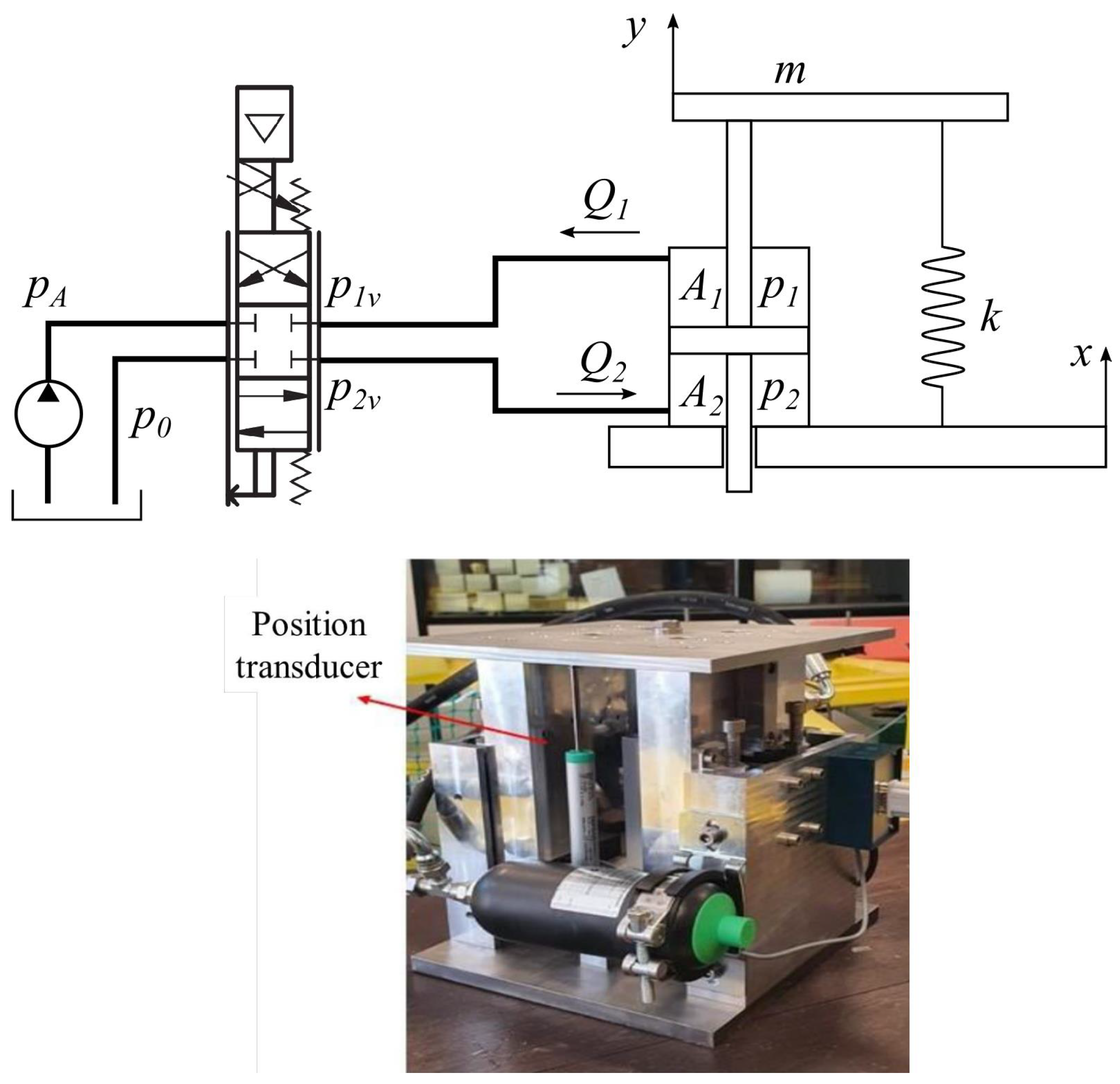
Figure 2 shows the schematic and the testbed of the hydraulic active suspension. The model is described by a set of equations related to: the dynamic equilibrium of the suspended body, the flow rates through hydraulic hoses 1 and 2, the inlet and outlet flow rates through the valve, and the dynamic equilibrium of the valve’s internal spool.
With reference to Figure 3, the dynamic equilibrium of the suspended body m gives:
m y ¨ + k u + p 1 A 1 p 2 A 2 = 0
where y is the displacement of the suspended body of mass m, x is the displacement of the vibrating platform acting as a disturbance on the system, u = y x is the relative displacement between the suspended body and the vibrating platform, k is the equivalent stiffness of the set of springs, and p i and A i are pressures and cross-sections of the cylinder chambers, respectively. Note that the relative displacement u is bounded by the cylinder stroke L c .
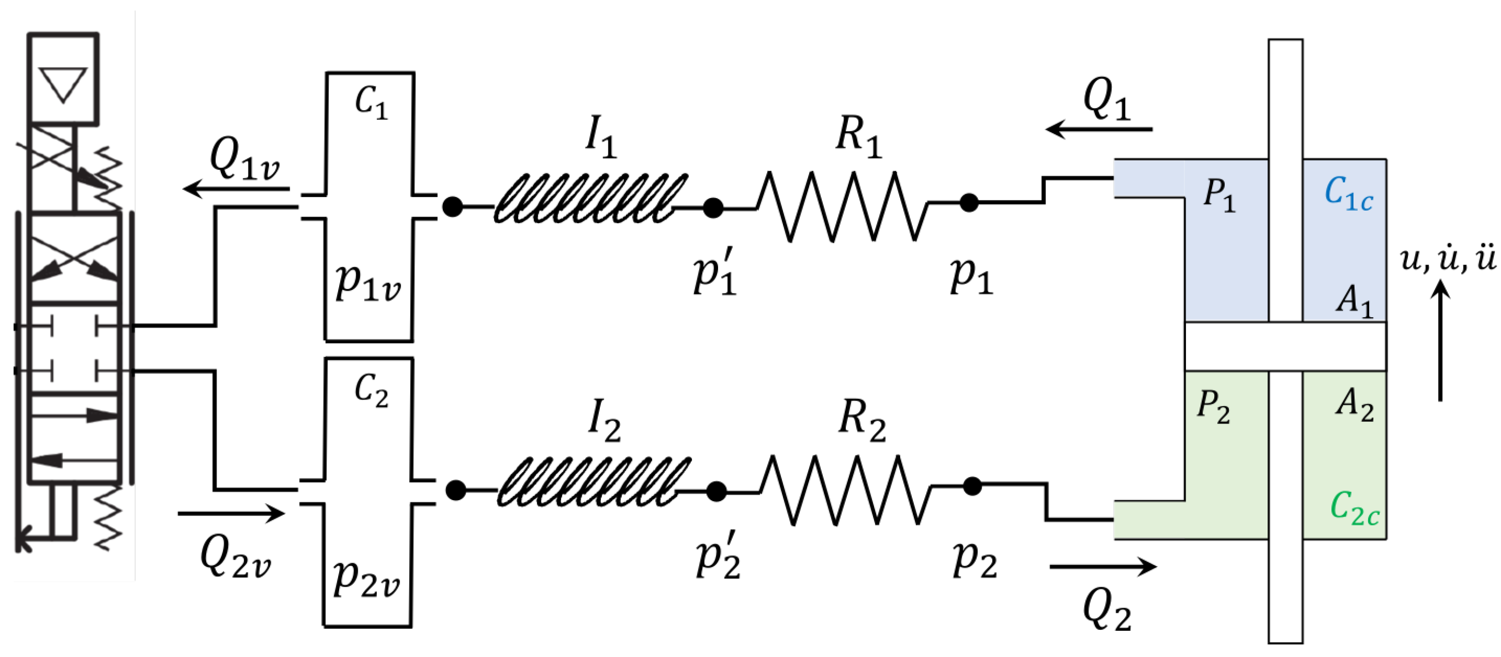
The flow rates through hydraulic hoses 1 and 2 are governed by the equations of the pressure drop along the two pipes and the equations of conservation of mass for the two pipes and the two chambers of the hydraulic actuator [27]:
p 1 p 1 v = R 1 Q 1 + I 1 Q ˙ 1
p 2 v p 2 = R 2 Q 2 + I 2 Q ˙ 2
Q 1 = u ˙ A 1 C 1 c p ˙ 1
Q 2 = u ˙ A 2 C 2 c p ˙ 2
Q 1 Q 1 v = C 1 p ˙ 1 v
Q 2 v Q 2 = C 2 p ˙ 2 v
where with reference to Figure 4, Q i are the volumetric flow rates at pipe connections with the chambers, Q i v are the volumetric flow rates at pipe connections with the valve, and p i v are the pressures at the pipe connections with the valve. Note that the flow rate Q 2 is assumed positive when directed from the valve to the lower chamber of the actuator, and conversely, the flow rate Q 1 is assumed positive when directed from the upper chamber of the actuator to the valve. Therefore, positive values of the flow rates are associated with a positive relative velocity u ˙ .
The hydraulic resistance R i , inertance I i , and capacitance C i of the hydraulic hoses as well as the capacitance of the hydraulic chambers C i c are defined as:
R i = 128 μ L i π d i 4
I i = 4 ρ L i π d i 2
C i = π L i d i 2 4 β
C i c = π L c D 2 d 2 8 β
where ρ , μ and β are the density, the compressibility modulus, and the dynamic viscosity of the mineral oil, respectively; L i and d i are the lengths and diameters of the hydraulic hose, respectively; L c , D, and d are the stroke, the external diameter, and the internal diameter of the cylinder chambers, respectively.
The inlet and outlet flow rates through the valve are given by:
Q 1 v = C d k a x v 2 ρ ( p 1 v p 0 ) if x v > 0 C d k a x v 2 ρ ( p A p 1 v ) if x v 0
Q 2 v = C d k a x v 2 ρ ( p A p 2 v ) if x v > 0 C d k a x v 2 ρ ( p 2 v p 0 ) if x v 0
where C d is the flow coefficient of the valve, x v is the displacement of the internal spool, the product k a x v is the cross-section of the hydraulic valve, and p A and p 0 are the feed and discharge pressures of the hydraulic supply circuit. Note that when the position of the internal spool of valve x v is positive, the valve connects the feed way to the bottom chamber of the actuator, and the top chamber of the actuator is connected to the discharge way. Positive values of the flow rates Q 1 v and Q 2 v generate a positive relative velocity of the suspended body u ˙ .
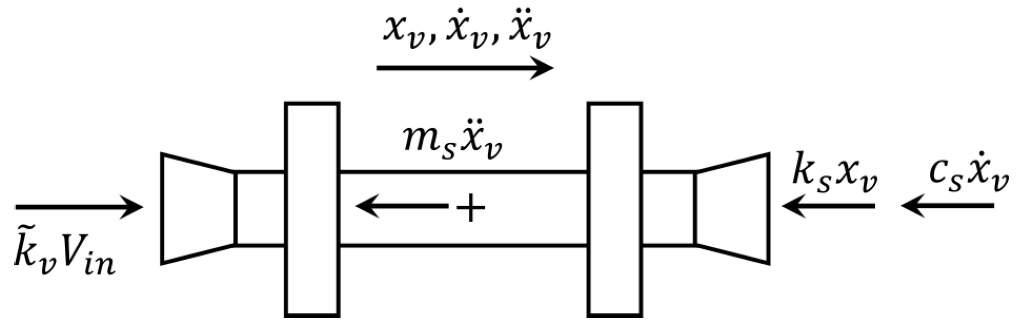
Moreover, the valve’s spool dynamic equation can be obtained using the free-body diagram in Figure 5, where m s is the mass of the internal spool, k s is a stiffness, c s is a viscous damping coefficient, and k ˜ v is a the proportional coefficient of the electromechanical power system of the valve expressed in N/V.
The force terms shown in Figure 5 can be recast to obtain:
x ¨ v ( t ) + 2 ζ s ω n x ˙ v ( t ) + ω n 2 x v ( t ) = ω n 2 k v V i n ( t τ )
where ω n 2 = k s / m s and ζ s = c s / ( 2 k s m s ) are the natural frequency and damping ratio of the proportional valve, respectively, k v = k ˜ v / k s is the static gain (m/V) of the proportional valve, and V i n is the command tension that is bounded to ±10 V and acts with a finite delay τ . Note that the displacement of the internal spool of the valve is bounded between ± x v , m a x .
Thus, the hydraulic dynamic system can be described by ten state variables and two input variables ( V i n and x).
The values of the parameters used in the numerical model of the system are introduced hereinafter. The suspension is characterized by a mass of the suspended body m = 11.7 kg and an equivalent stiffness of the set of springs k = 3680 N/m. The hydraulic cylinder employed in the active control of the suspension has a stroke of L c = 70 mm, a bore of D = 25 mm and a rod diameter of d = 18 mm. The two hydraulic hoses connecting the valve with the two chambers of the cylinder have length L i = 0.5 m and diameter d i = 10 mm. The feed and discharge pressures of the hydraulic supply circuit are p A = 100 and p 0 = 10 bar. The flow coefficient of the valve is C d = 0.1074 , and the coefficient k a = 25.1 mm is such that k a x v represents the cross-section area. Note that the flow coefficient C d is initially estimated, as suggested by the valve manufacturer, using Equation (12) with the nominal operating conditions of the valve, i.e., Q = 20 L/min and Δ p = 70 bar, and considering the completely open position of the valve. The static gain of the proportional valve is k v = 8 × 10 5 m/V, the natural frequency is ω n = 691 rad/s, the damping ratio is ζ s = 1.1 , and the maximum displacement of the spool is x v , m a x = 0.8 mm. Finally, the hydraulic fluid is characterized by density ρ = 840 kg/m 3 , viscosity μ = 0.02 kg/(m·s), and the compressibility β = 1200 MPa.

4. Experimental Validation of the Actuation System Model

The multi-physics model of the hydraulic active suspension system were implemented in Matlab Simulink, and the simulation results were compared to the data of the experimental tests performed on the active suspension system composed of the suspension, the control valve and the actuator.

4.1. Test

In order to validate the model, tests were performed by driving the electrovalve with a command signal V i n and by measuring the acceleration of the suspended body y ¨ and the relative position u between the suspended body and the vibrating platform, which was kept stationary ( x = 0 ). Tests were performed with harmonic excitation at discrete frequencies between 0.5 and 20 Hz and at discrete voltage amplitudes between 0.72 and 8 V. Table 1 shows the combination of frequencies and amplitudes. Note that not all combinations are possible, because at lower frequencies, bottoming conditions of the hydraulic cylinder occur.
Figure 6 shows the command tension V i n and the relative displacement response u between the suspended body and the vibrating platform due to a harmonic excitation at 5 Hz and voltage amplitude 2.1 V. Since the system is driven by a proportional flow rate control valve, the displacement response shows a phase delay with respect to the command tension.
The amplitudes of relative displacement responses u for all the tests in Table 1 are gathered in Figure 7. As expected, the higher the amplitude of the command tension, the higher the amplitude of the relative displacement. Moreover, the amplitude is inversely proportional to the frequency, due to the proportional flow rate control valve, such that a given amplitude of the command tension V i n provides almost the same amplitude of the relative velocity u ˙ .
The results of the experimental campaign are also gathered to obtain a magnitude and phase diagram of the whole hydraulic actuation system composed by the proportional flow rate control valve, the pipes connecting the valve to the cylinder, and the hydraulic actuator. Figure 8 shows the magnitude and phase diagram of the ratio u ˙ / V i n of the real system. Note that the plots for different values of the command tension amplitude are not the same, highlighting nonlinear behavior of the system. Each magnitude curve is almost constant up to a frequency of 10 Hz, i.e., in the bandwidth of interest for the whole-body vibrations. Moreover, the constant slope of the phase plots indicates the presence of a finite delay of the response, which can be estimated as τ = 0.0175 s. This value complies with the delay provided by the valve manufacturer.

4.2. Model Adjustment

The model described in Section 3 is implemented in the Simulink environment in order to have a digital twin for active control development. Therefore, numerical simulations using the same boundary conditions of the experimental tests are performed in order to obtain a numerical model that is able to retrace the response of the real system. In order to reproduce the main dynamic behavior of the system, a finite delay τ = 0.0175 s is considered in the dynamic equilibrium equation of the valve’s spool (see Equation (14)), and a flow coefficient C d = 0.1506 is set in the equation of the flow rate through the valve (see Equations (12) and (13)). Figure 9 shows the magnitude and phase diagram of the ratio u ˙ / V i n for the numerical model at different amplitudes of the command signal. The comparison between the magnitude and phase diagram of the model and that of the real system (see Figure 8) highlights that the model is able to reproduce the main dynamics of the real system, but it does not account for all the nonlinear phenomena.

5. Simplified Model

Although the nonlinear multi-physics model, outlined in Section 3, is able to retrace the main dynamics of the real system, a simplified model can be adopted for the development of a proper control system.
In the frequency band 0–20 Hz, in which experiments were conducted, the behavior shown in Figure 8 and Figure 9 can be approximated with the following transfer function, representing a second-order system with finite delay according to experimental findings:
G ( s ) = u ˙ ( s ) V i n ( s ) = s p 2 K g e s τ ( s 2 + 2 ζ p s p s + s p 2 )
where s p = 500 rad/s represents the pole location in the Laplace domain, K g = 133.25 mm/(s·V) is a static gain of the transfer function, ζ p = 0.05 is a damping factor, and τ = 17.5 ms is the finite delay.
Figure 10 shows that the transfer function G ( s ) is able to approximate the dynamics of the experimental system, and it can be used to design the control system.

6. Control of the Active Suspension System

The active control system should be able to simultaneously attenuate the acceleration transmitted from the vibrating platform to the suspended body and restore the hydraulic actuator at its half stroke position in order to avoid bottoming effects. These two conflicting requirements are satisfied by considering a slower controller for the position and a faster one for the acceleration.
The model of the active suspension system is built considering the transfer function H ( s ) = u ¨ / V i n = s G ( s ) , a proportional position controller P ( s ) = K p on the relative position signal u to maintain the actuator at its half stroke position, and an integrative controller I ( s ) = K i / s on the acceleration x ¨ of the vibrating platform, since the proportional flow rate hydraulic valve provides a relative velocity u ˙ proportional to the command tension V i n . Therefore, the control signal V i n can be expressed as the sum of two terms V 1 and V 2 generated by the controller P ( s ) and I ( s ) , respectively:
V i n ( s ) = V 1 ( s ) + V 2 ( s ) = K p u ( s ) + K i s x ¨ ( s )
The coefficients of the proportional and integrative controller are K p = 5 V/m and K i = 7.5 Vs/m, respectively.
The model shown in Figure 11 can be reduced in order to evaluate the transfer function T ( s ) = y ¨ ( s ) / x ¨ ( s ) , which represents the transmissibility of the active suspension system. Figure 12 shows the magnitude and the phase of the transfer function T ( s ) and highlights that the active control is able to attenuate the acceleration input up to 9 Hz, i.e., in almost all the frequency bands of interest for the whole-body vibrations. The transmissibility of the active suspension is compared with the transmissibility of the passive system, characterized by the same value of the suspended mass m and of the stiffness k with the presence of a viscous damper, acting in parallel to the stiffness, such as to produce a damping factor ζ = 0.3 . Although the active control system slightly amplifies the acceleration above 9 Hz, the acceleration spectrum that is input to the vibrating platform is given by the soil irregularities that are low-pass filtered by the suspension systems (tires, front axle suspension) of the agricultural machine [11]. Moreover, the vibrations are generally attenuated above 5 Hz by the seat cushion placed between the suspended mass and the operator [12]. Therefore, the input acceleration x ¨ to the vibrating platform is generally not relevant above 9 Hz. The passive system amplifies the vibrations in the band 0–4 Hz and attenuates the vibrations above 4 Hz.
In order to asses the effectiveness of the proposed control, the response of the model in Figure 11 is evaluated for different acceleration signals of the vibrating platform.
A first test considers a rapid variation of the vibrating platform position, obtained using a cycloidal law of the acceleration x ¨ ( t ) . Figure 13 shows the response of the active suspension and of the passive system for a position variation of 30 mm in 0.5 s of the vibrating platform. The acceleration results highlight that, for the active system, the feedforward controller is able to compensate for the acceleration of the vibrating platform, while the passive system introduces higher accelerations. However, the control system starts to reduce the acceleration of the suspended body with a delay equal to the finite delay τ considered in the model. Moreover, the displacement results show that the deformation u of the passive system is smaller than the deformation of the active system, but the feedback controller slowly resets the actuator in its central position by reducing the relative position error so that the system is ready to deal with other disturbances. Figure 14 shows the command tension V i n and the spool position x v for a rapid variation of the vibrating platform position. The results highlight the presence of a finite delay τ between the command tension and the actual displacement of the internal spool of the valve.
A second test simulates the effects of random soil irregularities. Due to the low-pass filtering effect of the tractor suspension system and of the seat cushion, the input acceleration x ¨ is generated as band-limited white noise in the frequency band [0.5, 5] Hz with a power spectral density of S 0 = 0.05 (m/s 2 ) 2 /Hz. Figure 15 shows the comparison between the response of the active suspension system and that of the passive system to the random vibration of the vibrating platform. In this case, the acceleration results show that the feedforward controller of the active system is able to isolate the acceleration of the vibrating platform, providing lower acceleration than the passive system. The root mean square value (RMS) of the acceleration x ¨ of the vibrating platform is 0.48 m/s 2 , the RMS of the acceleration y ¨ of the suspended body is reduced more than three times to 0.15 m/s 2 by the active system, and while using the passive system, the RMS of the acceleration y ¨ of the suspended body is 0.67 m/s 2 .
For the tests in Figure 13 and Figure 15, the relative displacement u is within the limits of the suspension system, and the one of the active system is larger than that of the passive system, highlighting the effectiveness of the active system in compensating for the soil irregularities by its own deformation, and thus reducing the acceleration of the suspended mass.
A last test aims at verifying the performance of the controller in Equation (16) on the multi-physics model, using the same input acceleration x ¨ generated for the previous test on the equivalent model. As expected, the results in terms of acceleration and displacement are quite similar to the results shown in Figure 15. The root mean square value of the acceleration y ¨ of the suspended body in this case is 0.16 m/s 2 . Moreover, the multi-physics model provides results that were not available using the equivalent model. In particular, Figure 16 shows the pressures p 1 and p 2 in the two chambers of the hydraulic actuator and the flow rates Q 1 and Q 2 between the valve and the actuator. The pressure results show that the pressure of the two chambers oscillates symmetrically around 55 bar, which is the mean value between the p A and p 0 , to generate the required control force. The flow rates, according to the positive directions shown in Figure 4, are equal and comply with the maximum flow rate of the considered electrovalve.

7. Conclusions

In this paper, a nonlinear multi-physics modeling of a hydraulic active suspension system for the operator’s seat of an agricultural tractor is carried out; specifically, the parameters of the control valve are identified, highlighting the presence of a finite time delay. Although the valve dynamics are faster than the actuator dynamics, the finite time delay significantly affects the behavior of the control system. The model is adjusted starting from the experimental data of the prototype to represent a digital twin of the active suspension system. A simplified linearized model is also obtained and employed to develop a proper controller that can simultaneously attenuate the accelerations transmitted from the vibrating platform to the suspended body and restore the hydraulic actuator at its half-stroke position to avoid bottoming effects. The hydraulic active suspension system is able to attenuate the acceleration in the frequency band of interest for the whole-body vibrations, and its performance is compared to that of a passive system. Finally, the designed controller is tested on the digital twin of the system to obtain meaningful additional information regarding internal quantities, such as fluid pressures and flow rates. Future work will focus on implementing more advanced control strategies to improve the performance of the active control system.

Author Contributions

For the research illustrated in the present paper, M.G.A., J.B., W.D. and A.F. carried out the conceptualization, investigation, methodology, and writing of the original draft; P.N. provided the laboratory resources for the experimental activities and carried out the project administration activity; all the authors contributed equally to review and editing of the manuscript. All authors have read and agreed to the published version of the manuscript.

Funding

This research was developed in the framework of the project BRIC-ID11 (2022) funded by INAIL (Italian National Institute for Insurance against Accidents at Work and Occupational Diseases).

Data Availability Statement

Not applicable.

Conflicts of Interest

The authors declare that they have no conflict of interest.

References

  1. Zeng, X.; Kociolek, A.M.; Khan, M.I.; Milosavljevic, S.; Bath, B.; Trask, C. Whole body vibration exposure patterns in Canadian prairie farmers. Ergonomics 2017, 60, 1064–1073. [Google Scholar] [CrossRef] [PubMed]
  2. Stayner, R. Whole-Body Vibration and Shock: A Literature Review: Extension of a Study of Overtravel and Seat Suspensions; University of Southampton, Institute of Sound and Vibration Research: Southampton, UK, 2001. [Google Scholar]
  3. Kim, J.; Dennerlein, J.; Johnson, P. The effect of a multi-axis suspension on whole body vibration exposures and physical stress in the neck and low back in agricultural tractor applications. Appl. Ergon. 2018, 68, 80–89. [Google Scholar] [CrossRef] [PubMed]
  4. Boshuizen, H.C.; Bongers, P.M.; Hulshof, C.T. Self-reported back pain in tractor drivers exposed to whole-body vibration. Int. Arch. Occup. Environ. Health 1990, 62, 109–115. [Google Scholar] [CrossRef] [Green Version]
  5. Bovenzi, M.; Betta, A. Low-back disorders in agricultural tractor drivers exposed to whole-body vibration and postural stress. Appl. Ergon. 1994, 25, 231–241. [Google Scholar] [CrossRef]
  6. Essien, S.K.; Trask, C.; Khan, M.; Boden, C.; Bath, B. Association between whole-body vibration and low-back disorders in farmers: A scoping review. J. Agromed. 2018, 23, 105–120. [Google Scholar] [CrossRef] [PubMed]
  7. Heidarian, A.; Wang, X. Review on Seat Suspension System Technology Development. Appl. Sci. 2019, 9, 2834. [Google Scholar] [CrossRef] [Green Version]
  8. Al-Ashmori, M.; Wang, X. A Systematic Literature Review of Various Control Techniques for Active Seat Suspension Systems. Appl. Sci. 2020, 10, 1148. [Google Scholar] [CrossRef] [Green Version]
  9. Zhao, Y.; Wang, X. A Review of Low-Frequency Active Vibration Control of Seat Suspension Systems. Appl. Sci. 2019, 9, 3326. [Google Scholar] [CrossRef] [Green Version]
  10. ISO 2631-1; Mechanical Vibration and Shock—Evaluation of Human Exposure to Whole-Body Vibration General Requirements. International Organization for Standardization: Geneva, Switzerland, 1997.
  11. Lines, J. Ride vibration of agricultural tractors: Transfer functions between the ground and the tractor body. J. Agric. Eng. Res. 1987, 37, 81–91. [Google Scholar] [CrossRef]
  12. Lewis, C.; Griffin, M. Evaluating the vibration isolation of soft seat cushions using an active anthropodynamic dummy. J. Sound Vib. 2002, 253, 295–311. [Google Scholar] [CrossRef]
  13. Commission Delegated Regulation (EU) No 1322/2014 of 19 September 2014 Supplementing and Amending Regulation (EU) No 167/2013 of the European Parliament and of the Council with Regard to Vehicle Construction and General Requirements for the Approval of Agricultural and Forestry Vehicles. 2018. Available online: http://data.europa.eu/eli/reg_del/2014/1322/oj (accessed on 26 June 2018).
  14. Zehsaz, M.; Sadeghi, M.H.; Ettefagh, M.M.; Shams, F. Tractor cabin’s passive suspension parameters optimization via experimental and numerical methods. J. Terramech. 2011, 48, 439–450. [Google Scholar] [CrossRef]
  15. Liao, X.; Zhang, N.; Du, X.; Zhang, W. Theoretical Modeling and Vibration Isolation Performance Analysis of a Seat Suspension System Based on a Negative Stiffness Structure. Appl. Sci. 2021, 11, 6928. [Google Scholar] [CrossRef]
  16. Hostens, I.; Deprez, K.; Ramon, H. An improved design of air suspension for seats of mobile agricultural machines. J. Sound Vib. 2004, 276, 141–156. [Google Scholar] [CrossRef]
  17. Soliman, A.; Kaldas, M. Semi-active suspension systems from research to mass-market—A review. J. Low Freq. Noise Vib. Act. Control 2021, 40, 1005–1023. [Google Scholar] [CrossRef] [Green Version]
  18. Nieto, A.; Morales, A.; Trapero, J.; Chicharro, J.; Pintado, P. An adaptive pneumatic suspension based on the estimation of the excitation frequency. J. Sound Vib. 2011, 330, 1891–1903. [Google Scholar] [CrossRef] [Green Version]
  19. Stein, G.; Ballo, I. Active Vibration Control System for the Driver’s Seat for Off-Road Vehicles. Veh. Syst. Dyn. 1991, 20, 57–78. [Google Scholar] [CrossRef]
  20. Talib, M.H.A.; Mat Darns, I.Z. Self-tuning PID controller for active suspension system with hydraulic actuator. In Proceedings of the 2013 IEEE Symposium on Computers & Informatics (ISCI), Langkawi, Malaysia, 7–9 April 2013; pp. 86–91. [Google Scholar] [CrossRef]
  21. Quaini, D.; Sazgetdinov, K.; Ivanov, V.; Ferrara, A. Optimization Based Sliding Mode Control in Active Suspensions: Design and Hardware-in-the-Loop Assessment. In Proceedings of the 2020 European Control Conference (ECC), Virtual Event, 12–15 May 2020; pp. 1607–1612. [Google Scholar] [CrossRef]
  22. East, W.; Turcotte, J.; Plante, J.S.; Julio, G. Experimental assessment of a linear actuator driven by magnetorheological clutches for automotive active suspensions. J. Intell. Mater. Syst. Struct. 2021, 32, 955–970. [Google Scholar] [CrossRef] [PubMed]
  23. Brunetti, J.; D’Ambrogio, W.; Fregolent, A. Analysis of the vibrations of operators’ seats in agricultural machinery using dynamic substructuring. Appl. Sci. 2021, 11, 4749. [Google Scholar] [CrossRef]
  24. Antonelli, M.G.; Brunetti, J.; D’ambrogio, W.; Fregolent, A.; Latini, F. Experimental identification of a pneumatic valve-cylinder system for attitude control. In Theoretical and Applied Mechanics—AIMETA 2022; Di Paola, M., Fratini, L., Micari, F., Pirrotta, A., Eds.; Materials Research Proceedings; MRF: Millersville, PA, USA, 2023; Volume 26, pp. 177–182. [Google Scholar] [CrossRef]
  25. Chen, P.C.; Huang, A.C. Adaptive Multiple-surface Sliding Control of Hydraulic Active Suspension Systems Based on the Function Approximation Technique. J. Vib. Control 2005, 11, 685–706. [Google Scholar] [CrossRef]
  26. Liu, Y.J.; Zeng, Q.; Liu, L.; Tong, S. An Adaptive Neural Network Controller for Active Suspension Systems with Hydraulic Actuator. IEEE Trans. Syst. Man Cybern. Syst. 2020, 50, 5351–5360. [Google Scholar] [CrossRef]
  27. Bolton, W. Basic System Models, System Models. In Mechatronics—Electronics Control Systems in Mechanical and Electrical Engineering; Pearson: Harlow, UK, 2015; pp. 413–448. [Google Scholar]
Figure 1. Prototype of the seat suspension.
Machines 11 00708 g001
Figure 2. Schematic and testbed of the hydraulic active suspension.
Machines 11 00708 g002
Figure 3. The free-body diagrams of the suspended body and the set of springs.
Machines 11 00708 g003
Figure 4. Lumped parameters of the hoses (hydraulic capacitances C, inertances I, resistances R).
Machines 11 00708 g004
Figure 5. Free-body diagram of the internal spool of the electrovalve.
Machines 11 00708 g005
Figure 6. Signals of the command tension V i n and relative displacement u between the suspended body and the vibrating platform. Harmonic excitation at 5 Hz and voltage amplitude 2.1 V.
Machines 11 00708 g006
Figure 7. Amplitude of relative displacement responses u for all tests.
Machines 11 00708 g007
Figure 8. Magnitude and phase diagram of the ratio u ˙ / V i n of the real system.
Machines 11 00708 g008
Figure 9. Magnitude and phase diagram of the ratio u ˙ / V i n of the model of the hydraulic actuation system.
Machines 11 00708 g009
Figure 10. Comparison between the transfer function G ( s ) and the ratio u ˙ / V i n of the real system for a value of the command tension amplitude V i n = 0.72 V.
Machines 11 00708 g010
Figure 11. Block diagram of the active suspension system.
Machines 11 00708 g011
Figure 12. Comparison of the transmissibility T ( s ) of the active suspension system with that of the passive system.
Machines 11 00708 g012
Figure 13. Comparison of the response of the active suspension system with that of the passive system to a rapid variation in the vibrating platform position. Acceleration of the vibrating platform x ¨ and of the suspended body y ¨ (top). Vertical position of the vibrating platform x, relative position of the suspended body u. and absolute position of the suspended body y (bottom).
Machines 11 00708 g013
Figure 14. Command tension V i n and spool position x v of the active suspension system for a rapid variation of the vibrating platform position.
Machines 11 00708 g014
Figure 15. Comparison of the response of the equivalent model of the active suspension system with that of the passive system to a random vibration of the vibrating platform. Acceleration of the vibrating platform x ¨ and of the suspended body y ¨ (top). Vertical position of the vibrating platform x and absolute position of the suspended body y (center). Relative position of the suspended body u (bottom).
Machines 11 00708 g015
Figure 16. Response of the active suspension system to the random vibration of the vibrating platform using the multi-physics model. Pressure in the two chambers of the hydraulic actuator (top). Flow rates between the valve and the actuator (bottom).
Machines 11 00708 g016
Table 1. Experimental tests on the testbed of the hydraulic active suspension. The X symbol indicates performed tests.
Amplitude [V]0.721.102.103.004.506.408.00
Frequency [Hz]
0.5X
1.0XX
2.0XXX
3.0XXXX
4.0XXXXX
5.0XXXXXX
6.0XXXXXXX
7.0XXXXXXX
8.0XXXXXXX
9.0XXXXXXX
10.0XXXXXXX
15.0XXXXXXX
20.0XXXXXX
Disclaimer/Publisher’s Note: The statements, opinions and data contained in all publications are solely those of the individual author(s) and contributor(s) and not of MDPI and/or the editor(s). MDPI and/or the editor(s) disclaim responsibility for any injury to people or property resulting from any ideas, methods, instructions or products referred to in the content.

