Article

Design of Novel Modified Double-Ended Forward Converter for Stepper Motor Drive

by
Shanmugavadivu Natarajan
1,*,
Raju Kannadasan
1,
Faisal Alsaif
2 and
Mohammed H. Alsharif
3
1
Department of Electrical and Electronics Engineering, Sri Venkateswara College of Engineering, Sriperumbudur 602117, India
2
Department of Electrical Engineering, College of Engineering, King Saud University, Riyadh 11421, Saudi Arabia
3
Department of Electrical Engineering, College of Electronics and Information Engineering, Sejong University, Seoul 05006, Republic of Korea
*
Author to whom correspondence should be addressed.
Machines 2023, 11(8), 777; https://doi.org/10.3390/machines11080777
Submission received: 19 June 2023 / Revised: 24 July 2023 / Accepted: 24 July 2023 / Published: 26 July 2023

Abstract

:
This paper presents the design and analysis of a modified double-ended forward converter (DEFC) for stepper motor-based robotic applications. The proposed converter topology provides galvanic isolation between the input and output while also higher efficiency with a smooth operative system, making it suitable for use in robotic systems that require both power and control signals to be transmitted. The paper also discusses the control strategy for the converter, which uses Proportional Integral (PI) to regulate the output voltage and current. The control strategy is implemented using a microcontroller-based system, which provides precise control of the output parameters. The converter is tested using a stepper motor-based load, and the results demonstrate the effectiveness of the proposed topology and control strategy. In addition to the experimental results, the paper also presents a detailed analysis of the converter’s performance. The analysis includes the input voltage and current, capacitor voltage, MOSFET parameters, output voltage and current, and calculation of efficiency. The analysis results show that the proposed converter topology and control strategy offer high efficiency comparing to existing converting approaches. Overall, the proposed double-ended forward converter offers a suitable solution for stepper motor-based robotic applications, providing efficient and reliable power and control signals. The results demonstrate the effectiveness of the proposed converter topology and control strategy, making it a promising option for use in future robotic systems.

1. Introduction

Stepper motors play a vital role in various applications, including robotics, automation, and industrial systems, due to their precise control and positioning capabilities. Designing efficient and reliable power converters for stepper motor drives is of great importance to optimize their performance and enhance overall system efficiency. The motivation for this research lies in addressing the need for improved power converter designs specifically tailored for stepper motor drives, aiming to achieve higher efficiency, better control, and enhanced performance. DC-DC converters are commonly used to power and control stepper motors, as they can provide the required voltage and current levels to the motor driver. Several studies have focused on the design, optimization, and control of DC-DC converters for stepper motors in robotic applications. Authors also proposed a bi-directional DC-DC converter for driving stepper motors in robotics, which can operate in both boost and buck modes depending on the motor direction. The proposed converter achieved a high conversion efficiency of up to 96% and was suitable for battery-powered robotic systems [1]. Authors also presented a high-voltage DC-DC converter for driving large stepper motors in industrial robotic applications. The proposed converter utilized a multi-stage architecture to achieve high voltage conversion ratios with high efficiency. The converter was capable of delivering up to 1 kV output voltage with an efficiency of up to 96% [2]. Additionally, a novel current-mode DC-DC converter was proposed for driving stepper motors in robotic applications. The converter utilized a modified PWM control scheme to improve the transient response and reduce the output ripple. The proposed converter achieved a high conversion efficiency of up to 94% and was capable of driving large stepper motors with high accuracy [3]. Overall, studies demonstrate the importance and potential of DC-DC converters for powering and controlling stepper motors in robotic applications. Further research is needed to optimize the performance and efficiency of these converters for specific robotic applications and to develop new control techniques that can improve the accuracy and reliability of stepper motor control.
In the field of stepper motor drives, researchers have explored various power converter topologies to improve efficiency and control. Among them, the modified double-ended forward converter (DEFC) has gained attention for its potential application in stepper motor drives. Several studies have focused on designing and implementing novel variations of the modified double-ended forward converter to enhance its performance specifically for stepper motor drives. These studies investigate different aspects, such as control strategies, efficiency optimization, voltage ripple reduction, and transient response improvement. Notably, the DEFC is a type of DC-DC converter that has gained attention for its potential use in robotic applications. The DEFC has several advantages over other DC-DC converter topologies, including high efficiency, low output ripple, and bi-directional power flow. These features make it an attractive option for powering and controlling stepper motors in robotic systems. It is also proposed the use of a DEFC for driving a stepper motor in a robotic end-effector. The DEFC was designed to operate in both boost and buck modes, depending on the direction of the motor, and was controlled using a pulse width modulation (PWM) scheme. The proposed system achieved a high conversion efficiency of up to 95% and demonstrated good transient response and output regulation [1]. Some work presented a DEFC-based system for driving a micro-stepping motor in a robotic manipulator. The DEFC was optimized using a genetic algorithm to achieve high efficiency and minimal output ripple and was controlled using a digital signal processor (DSP). The proposed system achieved a high conversion efficiency of up to 96% and demonstrated good performance in both steady-state and dynamic operating conditions [4]. In a third study, a DEFC-based system was proposed for driving a high-torque stepper motor in a robotic gripper. The DEFC was designed to operate in a bi-directional power flow mode and was controlled using a proportional-integral (PI) control scheme. The proposed system achieved a high conversion efficiency of up to 94% and demonstrated good performance in terms of torque control and position accuracy [5]. These studies demonstrate the potential of DEFCs for powering and controlling stepper motors in robotic applications. Further research is needed to optimize the performance and efficiency of DEFCs for specific robotic applications and to develop new control techniques that can improve the accuracy and reliability of stepper motor control.
In today’s world, robotics, automation, and industrial systems are rapidly advancing, and stepper motors play a vital role in these applications due to their precise control and positioning capabilities. Stepper motors require efficient and reliable power converters to optimize their performance and overall system efficiency. DC-DC converters have been commonly used for powering and controlling stepper motors, offering the required voltage and current levels to motor drivers. However, there is a need for further research to develop specialized power converter designs tailored for stepper motor drives in specific robotic applications.
The specific context and problems of the research presented in this work focuses on exploring and optimizing the performance of DC-DC converters for powering and controlling stepper motors in robotic applications. The study highlights the modified double-ended forward converter (DEFC) as a potential topology to address the challenges of efficiency and control in stepper motor drives.
The motivation behind this study lies in addressing the need for improved power converter designs that can cater to the unique requirements of stepper motor drives in robotics. By optimizing the performance and efficiency of these converters, robotic systems can achieve higher precision, better control, and enhanced overall performance. The DEFC has gained attention for its potential application in stepper motor drives due to its advantages in terms of efficiency, low output ripple, and bi-directional power flow. However, further exploration is necessary to fine-tune the DEFC and develop new control techniques to maximize its effectiveness in specific robotic applications. This forms state of art this work specifically on the performance assessment in terms of efficiency.
The subsequent sections of the article are structured in the following manner: Section 2 elucidates the meticulous literature survey and articulates the problem statement; Section 3 expounds upon the extensive system modeling using the Simulink model and introduces the proposed converter; Section 4 offers an in-depth analysis of the results, encompassing both simulated and experimental outcomes, along with detailed discussions; and Section 5 culminates the work by presenting pivotal findings and conclusions.

2. Literature Review and Problem Description

Based on the research background, a comparison table of the recent trends of DC-DC Converter in different works and, along with their advantages, disadvantages, attained outcomes, research gaps, and references, are listed below in Table 1:
To summarize the merits and drawbacks of the different types of converters discussed in the above table, the following points are derived to show the significant values and differences:
Significant values:
  • All converters provide isolation between the input and output, ensuring electrical safety and protection;
  • They are designed for high power applications, offering high efficiency and power density;
  • The converters aim to improve transient response and reduce voltage stress in their respective designs;
  • Research gaps exist across all converter types, including the need for optimization under different load conditions, reducing complexity and cost, and improving efficiency.
Differences:
  • Circuit Complexity: Certain converters (e.g., Double-Ended Forward Converter with Primary-Side Double-Pulse Modulation and Secondary-Side Synchronous Rectification) are more complex than the Flyback converter;
  • Output Voltage Ripple: The mentioned converters (e.g., Double-Ended Forward Converter with Primary-Side Double-Pulse Modulation and Secondary-Side Synchronous Rectification) exhibit higher output voltage ripple;
  • Control Techniques: Dual Active Bridge Converter and Double-Ended Forward Converter with Active Clamp Reset demand complex control schemes;
  • Cost and Number of Components: High-Frequency Dual-Active-Bridge DC-DC Converter and Double-Ended Forward Converter with LLC Resonant Tank are costlier due to complex circuitry;
  • Renewable Energy Applications: Double-Ended Forward Converter for Renewable Energy and High-Efficiency Double-Ended Forward Converter are designed for renewable energy, offering good performance;
  • Optimization Parameters: Research lacks optimization of parameters (e.g., transformer turn ratio, switching frequency, duty cycle) for optimal efficiency in converters.
In summary, while all the discussed converters provide isolation, high efficiency, and suitability for high power applications, their specific advantages and disadvantages differ in terms of circuit complexity, output voltage ripple, control techniques, cost, suitability for renewable energy applications, integration of advanced features, application in emerging technologies, and optimization parameters. Further research is needed to address these differences and improve the overall performance and efficiency of DC-DC converters in various applications.
The field of research pertains to the design and optimization of power converters, specifically DC-DC converters, for powering and controlling stepper motors in various robotic applications, including robotics, automation, and industrial systems. Stepper motors are essential components in these applications due to their ability to provide precise control and positioning capabilities. Efficient and reliable power converters are crucial to ensure the optimal performance of stepper motors and overall system efficiency. The relevance of the problem lies in the ever-growing demand for robotics and automation in various industries, where precise and efficient control of stepper motors is essential. By developing specialized power converters tailored for stepper motor drives, researchers aim to enhance the accuracy, reliability, and overall performance of robotic systems. These advancements can lead to more sophisticated robotic applications, better industrial automation, and increased productivity.
Researchers have extensively studied different aspects of power converters for stepper motors, including various converter topologies, control techniques, and efficiency optimization. Among the explored converters, the modified double-ended forward converter (DEFC) has gained attention for its potential application in stepper motor drives. The DEFC offers advantages, such as high efficiency, low output ripple, and bi-directional power flow, making it an attractive option for robotic applications. Previous researchers have proposed and investigated various DEFC-based systems to drive stepper motors in different robotic applications. They have explored control strategies, efficiency optimization, voltage ripple reduction, and transient response improvement. Some researchers have focused on bi-directional DEFCs capable of operating in both boost and buck modes, depending on the motor’s direction, to achieve higher efficiency and better performance.
Additionally, other studies have optimized DEFCs using genetic algorithms, digital signal processors (DSPs), and proportional-integral (PI) control schemes to achieve high efficiency, minimal output ripple, and excellent performance in both steady-state and dynamic conditions. While previous research has shown promising results, there is still a need for further exploration to fine-tune DEFCs and develop new control techniques to maximize their effectiveness in specific robotic applications. Furthermore, researchers need to address specific challenges, such as load condition optimization, reducing complexity and cost, and improving overall efficiency to propel the field of power converters for stepper motor drives forward. By addressing these issues, researchers can contribute to the advancement of robotic technologies and the broader field of automation, ultimately benefiting various industries and enhancing the capabilities of robotic systems.

3. Methodology

3.1. Modelling of the System

The proposed system incorporated a modified double-ended forward converter (DEFC) for controlling stepper motors in robotic applications. It employed both open-loop and closed-loop converting processes to achieve precise motor control. The open-loop process allowed for initial testing and observation of the converter’s behavior without feedback control. On the other hand, the closed-loop control utilized a feedback mechanism to continuously adjust the stepper motor’s operation, ensuring it produced the desired output accurately.
The closed-loop control system played a vital role in achieving the desired motor output, as it compared the actual motor performance with the desired setpoint and made real-time adjustments accordingly. This feedback loop enabled the system to maintain accuracy and stability even in the presence of external disturbances.
To illustrate the system’s architecture, Figure 1 depicted the block diagram of the proposed setup. The DEFC, integrated with both open- and closed-loop control, was responsible for converting the input power into the required output for precise motor control.
The proposed system was designed to power and control a stepper motor using a 100 V DC source connected to a converter. The converter was based on the double-ended forward converter (DEFC), capable of operating in both buck and boost modes. However, for the specific robotic applications, the DEFC was configured to function in the buck mode. The speed control of the stepper motor was achieved through closed-loop control, ensuring precise and accurate motor performance.
To evaluate the system’s performance, simulations were conducted in both open-loop and closed-loop configurations. The open-loop simulation tested the converter’s behavior without feedback control while the closed-loop simulation involved the implementation of the closed-loop control system. The closed-loop control system used a feedback mechanism to continuously adjust the motor’s speed based on the desired output and actual performance.
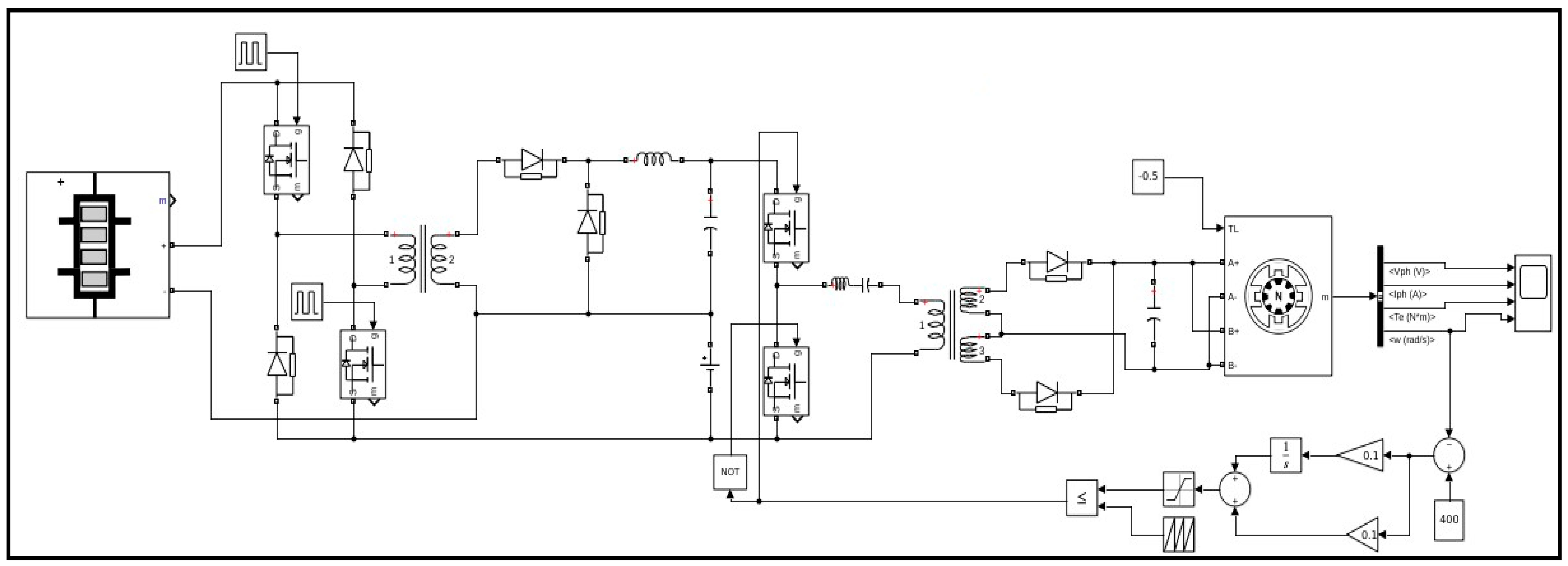
The closed-loop control system was implemented using a Simulink module, as shown in Figure 2. This module illustrated the control algorithm and its interaction with the converter and stepper motor. The feedback signals enabled real-time adjustments to the motor’s speed, ensuring it followed the desired trajectory accurately.

3.2. Proposed Converter Topology

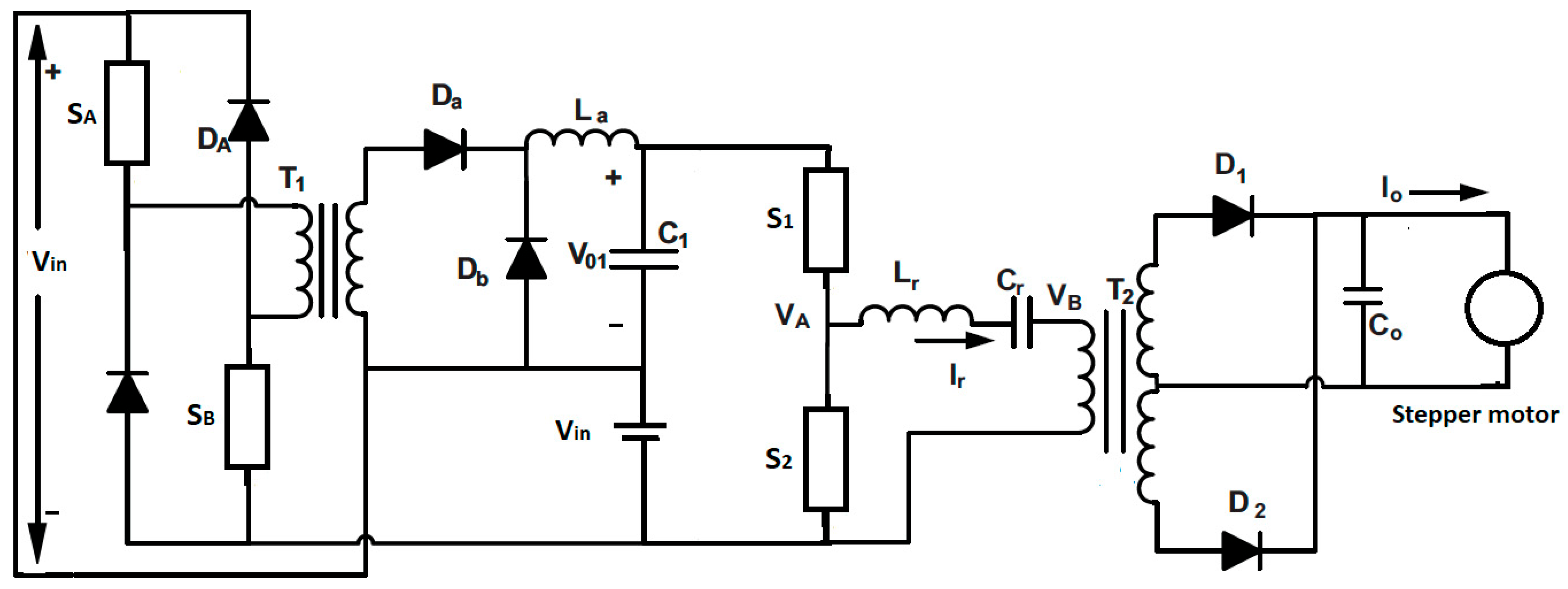
The proposed DEFC based on the stepper motor configuration utilized a series resonant converter to supply power to the stepper motor. The input to the series resonant converter was the sum of the DC grid voltage and the output of the forward converter, which acted as a current regulator for the stepper motor load (see Figure 3). By controlling the duty ratio of the forward converter switches, the load current of the stepper motor could be regulated. The majority of power supplied to the stepper motor was through the series resonant converter while the forward converter only processed a small amount of the lamp power to regulate the current. As a result, the losses in the forward converter were minimal, and the series resonant converter can be operated at a fixed switching frequency. Due to this, the proposed converter had significant and scientific values to enhance the performance of the presented topology.
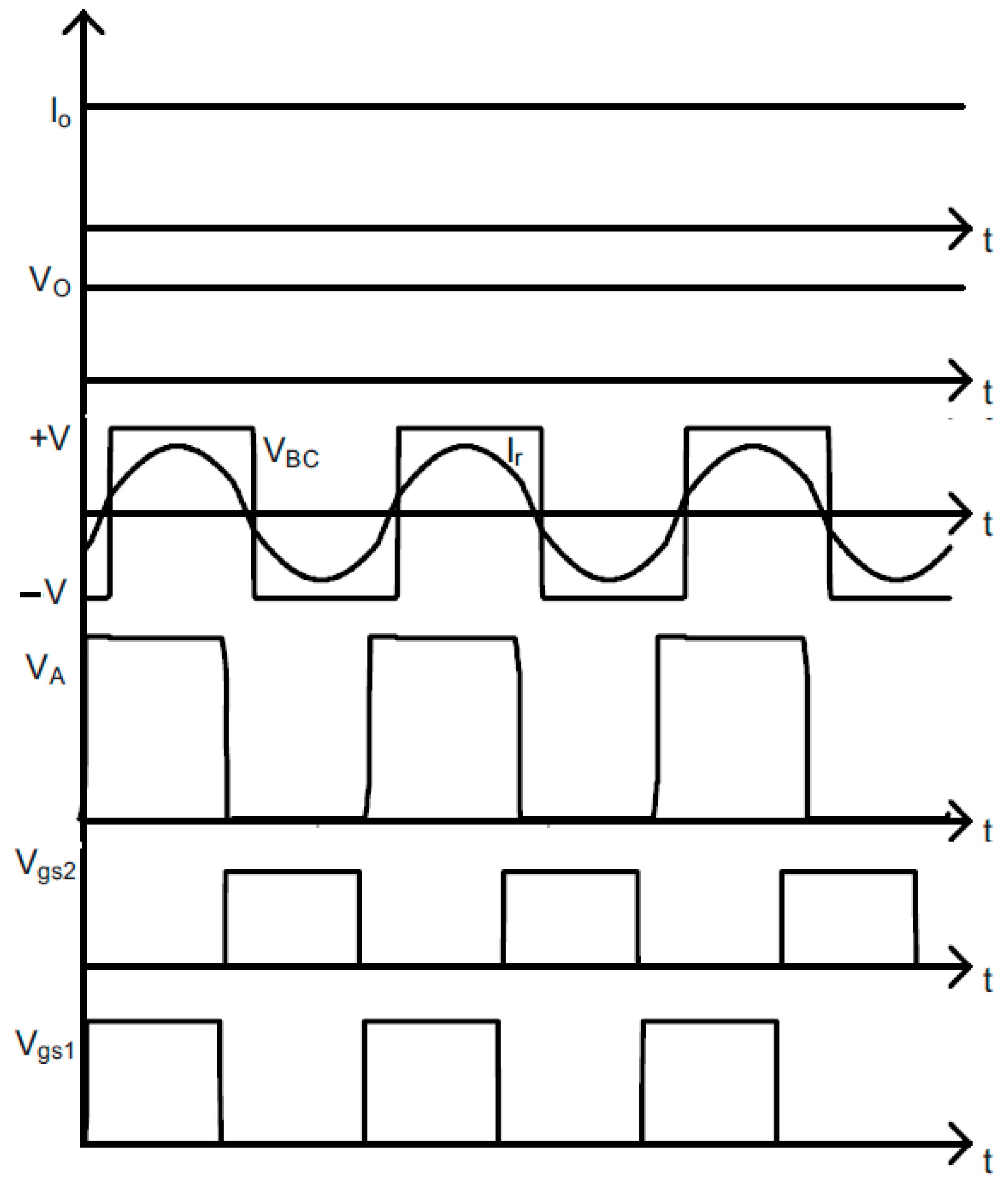
The input voltage of the series resonant converter was a combination of the DC-grid voltage (VDC) and the output voltage (V01) of the double-ended forward converter (DEFC). The DEFC ran at a consistent frequency while its duty cycle was adjusted to modify the output voltage and ensure a steady input voltage for the series resonant converter, despite fluctuations in the DC-grid voltage. The switches of the resonant converter operated at a fixed frequency with a 50% duty cycle, and their corresponding waveforms are illustrated in Figure 4.
The gate pulses applied to switches S1 and S2 are referred to as Vgs1 and Vgs2, respectively. The operation of the resonant circuit involved three stages, which were the half-bridge circuit, resonant circuit, and rectification and filter stage. The half-bridge circuit generated a unidirectional square voltage (VA) that was fed to the resonant circuit. The resonant circuit produced a bidirectional output voltage that was then sent to a transformer, where the secondary voltage was rectified. The resonant circuit also permitted a sinusoidal fundamental component of current, as shown in Figure 4. The half-bridge circuit switches achieved zero voltage switching (ZVS) due to the resonant circuit, which reduced switching losses and enhances efficiency. The half-bridge SRC operated with a constant frequency and duty ratio, making it easier to design the resonant components and achieve ZVS for a wide range of input supply variations. The amount of power processed by DEFC depended on its output voltage, but since it contributed only a small fraction of the input voltage to the SRC, it processed less power and was therefore more efficient. To achieve dimming, a logical AND operation of a 200 Hz signal and a 200 kHz signal was applied to the lower switch of the half-bridge circuit, allowing for control of the duty ratio of the 200 Hz signal to achieve the desired level of dimming. From above complications, the following improvements could be done:
  • The current sensitive outputs could be used to drive the motor drives (servo motor, stepper motors, etc.,) in robotic applications;
  • The control of the motor drives could be done using simple PWM techniques.
The capacitive output voltage of the proposed DEFC could be computed using the following equation:
V 01 = V D C n 1 D a
where V01 represented the output voltage of a converter, VDC was the input voltage, n1 represented the turns ratio of the transformer, and Da denoted the duty cycle.
Then, the minimum inductance ( L a , m i n ) offered by the proposed converter was defined as:
L a , m i n = ( 1 D a ) R a 2 f s
In this context, ‘fs’ referred to the operating frequency of the switches in DEFC while ‘Ra’ denoted the equivalent load resistance at the output of DEFC. When the duty ratio (D1) was set to 0.5, Ra was found to be 33.1, and the switching frequency of the DEFC switches was 50 kHz; the minimum value for La was calculated to be 166.5 μH. To maintain continuous conduction, La had to be kept at 250 μH. For smooth conduction, La had to be greater than La, min. The half-bridge inverter ( V i n ) was supplied with a voltage that was the sum of the output voltage of DEFC and the DC-grid voltage.
V i n = V D C + V 01
Vin was supplied to the half-bridge inverter, and the classical fundamental approximation was utilized to analyze the series resonant circuit and determine the voltage gain. As per the fundamental approximation, only the fundamental voltage component that was applied to the resonant circuit contributed to the transfer of power to the output. The rectifier on the secondary side of the transformer acted as an impedance transformer, with the equivalent resistance of the load differing from the actual resistance. The input current to the rectifier was Iac while the voltage was VR. The average value of Iac at the output was Io. Therefore, Iac was derived from I0 using Equation (4).
I a c = π I 0 2 s i n ω t
V R = + V 0   if   s i n ω t > 0
V R = V 0   if   s i n ω t < 0
where V0 was the output voltage and the fundamental component ( V R F ) of V0 was given as:
V R F = 4 V 0 π s i n ω t
The fundamental component of Va was involved in power transfer, and the load equivalent resistance ( R a c ) was calculated using the formula below:
R a c = V R F I a c = 8 V 0 π 2 I 0 = 8 π 2 R 0
In addition, the transformer turns ratio was taken as n = Nprimary/Nsecondary. Then, the Primary side equivalent resistance was given as follows:
R a c = 8 n 2 π 2 R 0
The load side provided an effective resistance of R0. The stepper motor equivalent circuit featured a resistance ‘rd’ connected in series with a voltage Vth and an ideal diode. Simulations of the proposed converter were conducted under the assumption that the rated DC-grid voltage was 95 V, though the proposed configuration was also suitable for high voltage applications, such as a DC-grid voltage of 380 V. The input voltage to DEFC was drawn from the DC-grid at a voltage of 95 V. The half-bridge inverter was supplied with a voltage that was a combination of the output voltage of DEFC and the DC-grid voltage. The half-bridge inverter was fed a constant voltage of 110 V irrespective of any variations in the DC-grid voltage.

4. Results and Discussion

4.1. Simulated Results

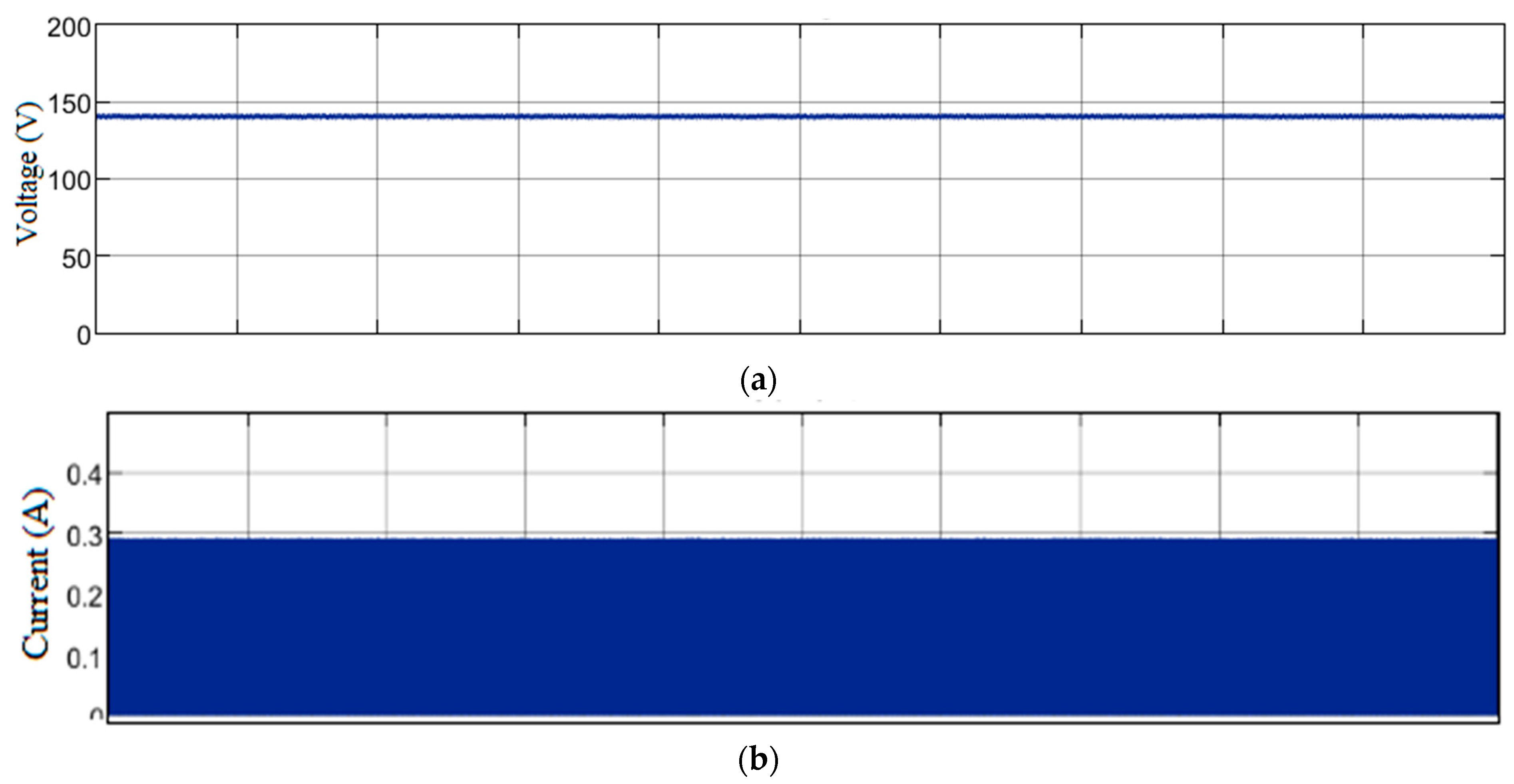
In this proposed work, the DEFC operates with a fixed input voltage, which is typically obtained from a DC power source as mentioned in the above section. This input voltage of the DEFC can vary depending on the specific application requirements. This DEFC is designed to convert this input voltage into a regulated DC voltage that is suitable for powering a load, such as stepper motors in robotics applications. The input voltage of this proposed system is maintained to be 140 V as illustrated in Figure 5a.
The input current of the DEFC depends on the output power and efficiency of the proposed converter. The DEFC is known for its high efficiency due to the use of a transformer with a high turn’s ratio, which helps to reduce losses. In addition, DEFCs typically operate at a high frequency, which further improves efficiency by reducing the size of the magnetic components and minimizing switching losses. These factors help to minimize the input current required for a given output power. Based on this, the input current of the proposed converter is obtained from the simulation and found to be 0.3 A as depicted in Figure 5b.
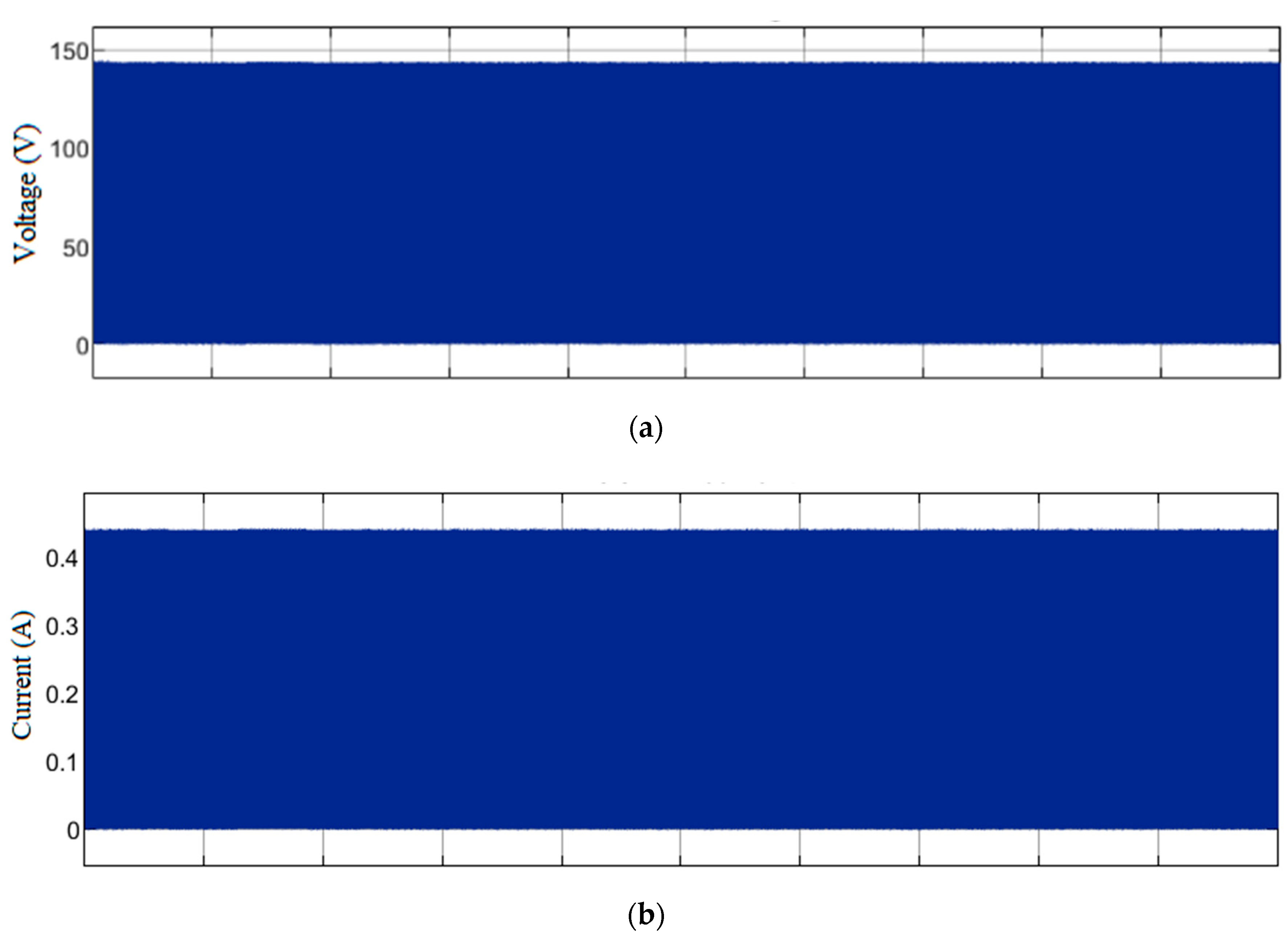
In a double-ended forward converter, mutual inductances play a crucial role in transferring energy from the input to the output. The converter uses two transformers with mutual inductances, one for the forward mode and the other for the reverse mode of operation. During the forward mode, the input voltage is applied to one transformer, and the current in the primary winding of this transformer produces a magnetic field. This magnetic field induces a voltage in the secondary winding of the same transformer and in the primary winding of the other transformer due to mutual inductance. The induced voltage in the secondary winding of the first transformer is rectified and filtered to obtain the output voltage. During the reverse mode, the input voltage is applied to the other transformer, and the current in the primary winding of this transformer produces a magnetic field. This magnetic field induces a voltage in the secondary winding of the same transformer and in the primary winding of the other transformer due to mutual inductance. The induced voltage in the primary winding of the first transformer is rectified and filtered to obtain the input voltage. The mutual inductance between the two transformers in a double-ended forward converter is typically designed to be as high as possible to ensure efficient energy transfer between the input and output. This is because a higher mutual inductance allows for a greater transfer of energy between the two transformers, which reduces the losses in the system. This converter has the mutual inductance of maximum allowable voltage 70 V at the primary and the secondary voltage. Figure 6 shows the obtained range of voltage and current on the mutual inductances, which show about 142 V and 05 A, respectively.
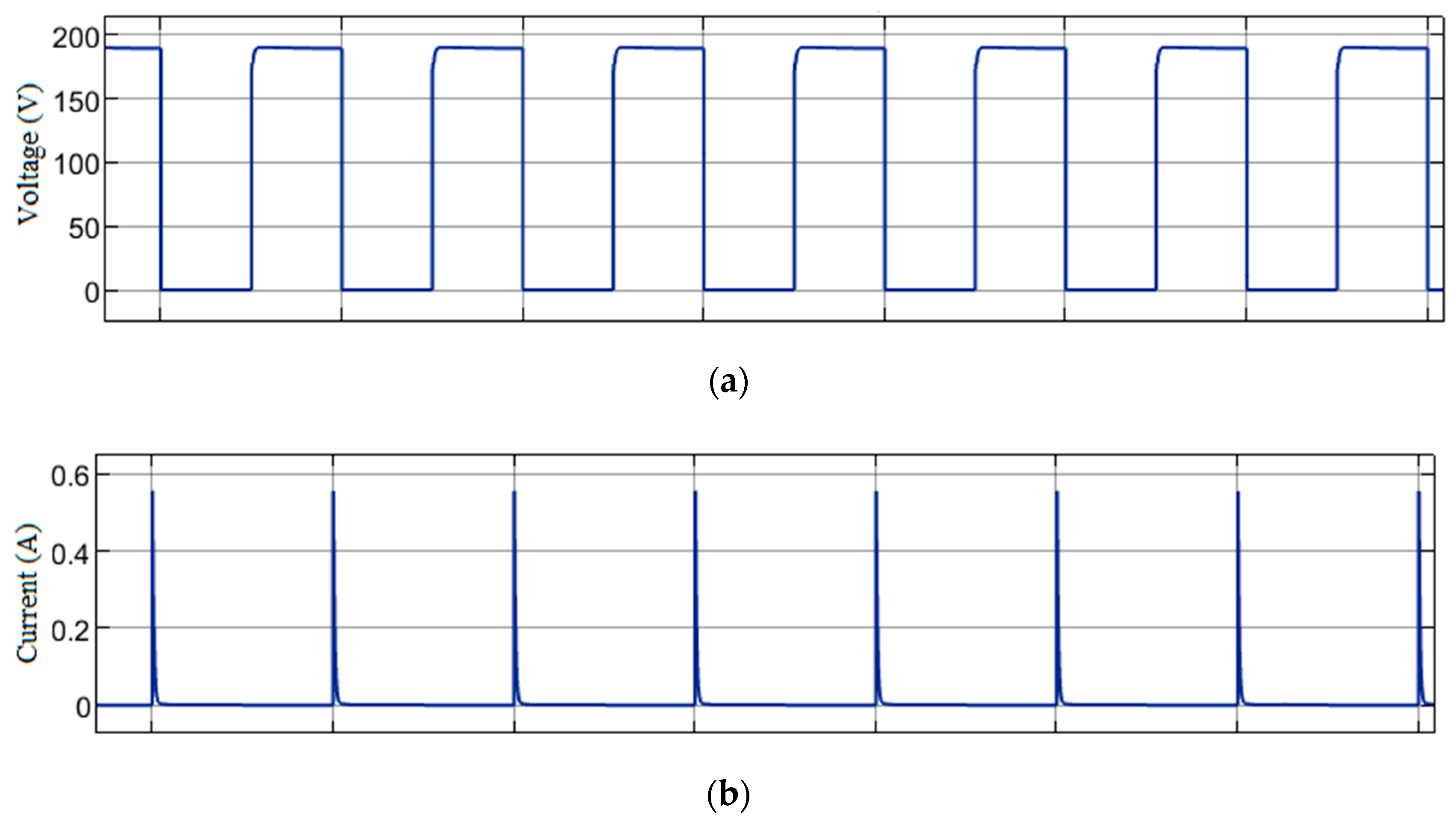
The MOSFETs in a double-ended forward converter are used as switches to control the flow of the current through the two transformers. They are used to switch the input voltage between the two transformers in a push–pull fashion so that energy is transferred from the input to the output. The drain-source voltage rating is the maximum voltage that can be applied across the drain and source terminals of the MOSFET. Its rating should be chosen to be greater than the maximum input voltage of the converter to ensure that the MOSFETs can withstand the voltage stress. Similarly, the drain current rating is the maximum current that can flow through the MOSFET. This rating should be chosen to be greater than the maximum output current of the converter to ensure that the MOSFETs can handle the current without being damaged. Therefore, the current and voltage characteristics of the proposed converter is assessed and illustrated in Figure 7. The converter switches are operated at a duty cycle of 0.5 with a low voltage and current stresses. The below figure shows the MOSFET switch parameters and found to be 0.4 A of current and 180 V of voltage.
The output voltage and current of a double-ended forward converter depend on several factors, including the input voltage, transformer turns ratio, and duty cycle of the MOSFETs. The converter is designed to step down the input voltage and provide a regulated output voltage to power a load. During the operation of the converter, the input voltage is first applied to one of the transformers while the other transformer is in the off state. The energy is stored in the transformer, and when the MOSFETs are switched, the energy is transferred to the output. The duty cycle of the MOSFETs determines the amount of energy transferred, and thus, it affects the output voltage and current.
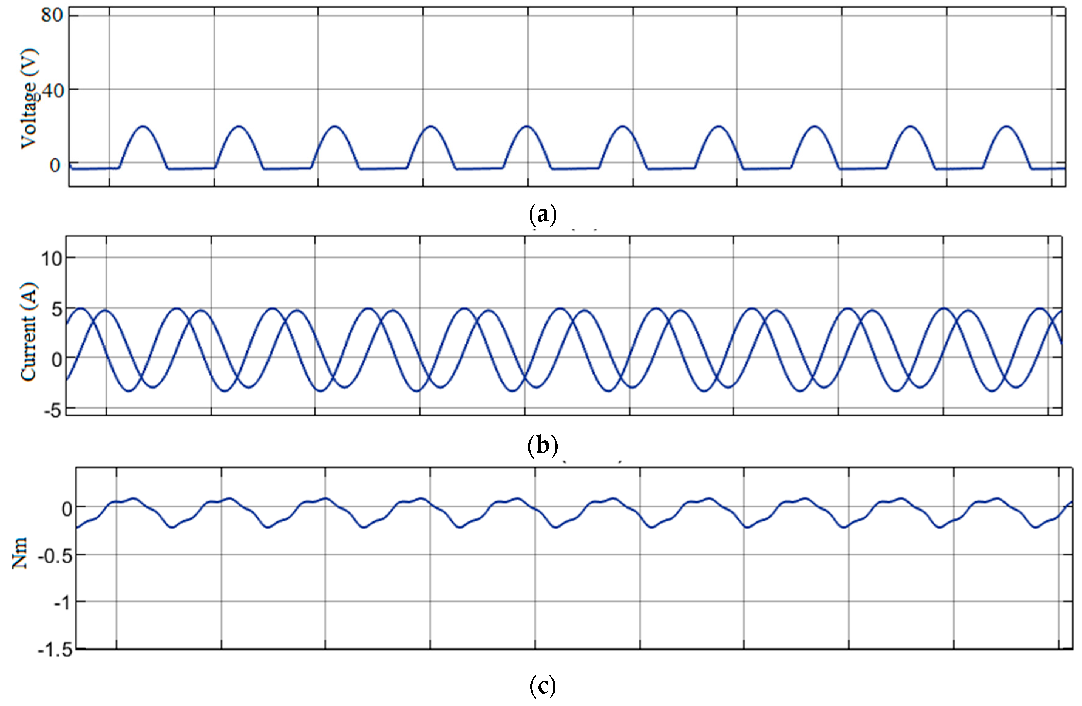
The output voltage of the converter can be regulated by using a feedback loop that compares the output voltage to a reference voltage and adjusts the duty cycle of the MOSFETs accordingly. The feedback loop ensures that the output voltage remains constant even when there are changes in the input voltage or load conditions. The output voltage can be higher or lower than the input voltage depending on the transformer turn ratio and duty cycle of the MOSFETs. Therefore, the output voltage of the proposed converter is observed that shows the scale of 20 V as illustrated in Figure 8a. Further, the output current of the converter is determined by the load resistance and the output voltage. As the load resistance decreases, the output current increases, and vice versa. The maximum output current is limited by the maximum current rating of the MOSFETs and other components in the circuit. The output current is obtained as a smooth curve and shows the range of 5 A as depicted in Figure 8b.
The stepper motor can be driven by a double-ended forward converter to control its voltage, current, torque, and speed. The voltage and current supplied to the stepper motor by the converter are controlled by adjusting the duty cycle of the MOSFETs. The duty cycle determines the amount of time that the MOSFETs are switched on, and thus, the amount of energy transferred to the motor. By adjusting the duty cycle, the voltage and current supplied to the motor can be varied to control its speed and torque. They found to be smooth, and the values are 20 V of current and 5 A of current (Figure 9a,b). In addition, the torque of the stepper motor is proportional to the current flowing through it. Therefore, by increasing the current supplied to the motor, its torque can be increased. This allows the motor to move heavier loads or operate in applications that require higher torque. This value is evaluated and illustrated in Figure 9c that shows about 0.2 N. Further, the speed of the stepper motor is determined by the frequency of the pulses supplied to it. The pulses cause the motor to move in discrete steps, and the frequency of the pulses determines the speed of the motor. By adjusting the frequency of the pulses, the speed of the motor can be controlled. Therefore, it shows the smooth values of speed about 450 RPM as depicted in Figure 9d.

4.2. Hardware Module

The hardware model of a double-ended forward converter typically consists of several components arranged in a specific circuit configuration. These components are presented in the Table 2:
The hardware model of the converter is typically designed using simulation software and then implemented on a printed circuit board (PCB) for testing and verification. The PCB includes all the components of the circuit and is designed to ensure that the circuit operates within the desired voltage, current, and power specifications. During operation, the MOSFETs switch on and off at a specific frequency and duty cycle, transferring energy from the primary winding of the transformer to the secondary winding. The energy is then rectified by the diodes and filtered by the capacitors before being supplied to the output load. The proposed prototype model is drawn as a block diagram and given in Figure 10. It consists of a 230 V supply stepped down to 12 V using a transformer. The transformer output is given to the rectifier for the AC to DC conversion. The DC output acts as an input to the double-ended forward converter, and the output of the converter is connected to the load.
Based on the block diagram, the circuit is designed as the prototype model, and its overall design is illustrated in Figure 11.
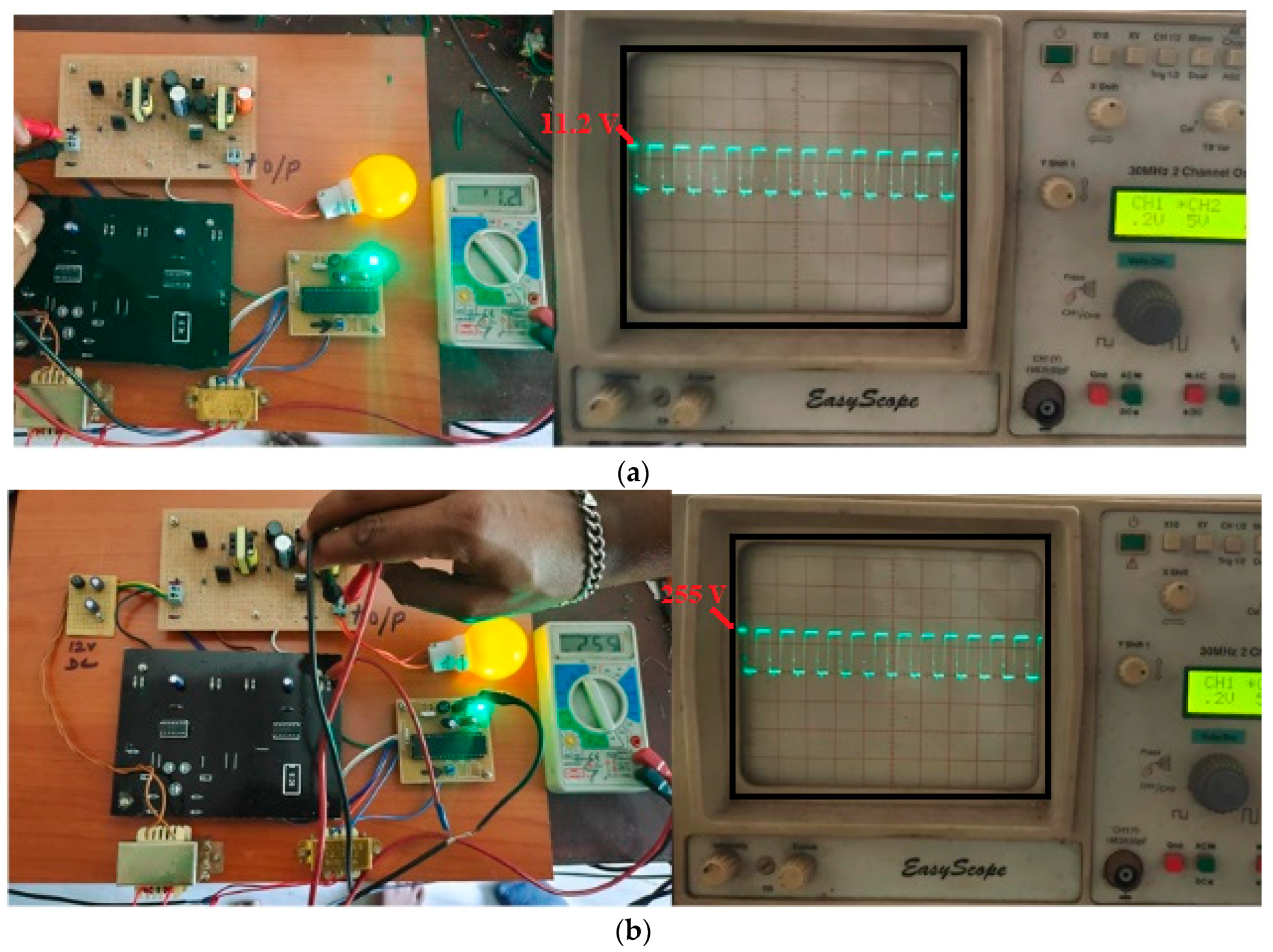
The hardware consists of the transformer of 230 V to 12 V stepdown. The stepped down AC voltage of 12 V is rectified using the diode bridge rectifier. The DC now serves as an input to the proposed double-ended forward converter. The MOSFET driver circuit is created and managed by the PIC16F877a microcontroller. To power the PIC controller, the transformer steps down the voltage from 230 V to 6 V; this is subsequently rectified. A regulator, IC LM7805, is employed to provide a regulated output. The hardware input and output measurements are taken using a multimeter and CRO. Figure 12 shows the results measured during the operation for the measurement of voltages. Specifically, Figure 13a shows the input voltage of 11.2 V, and Figure 13b shows the output voltage of 255 V.
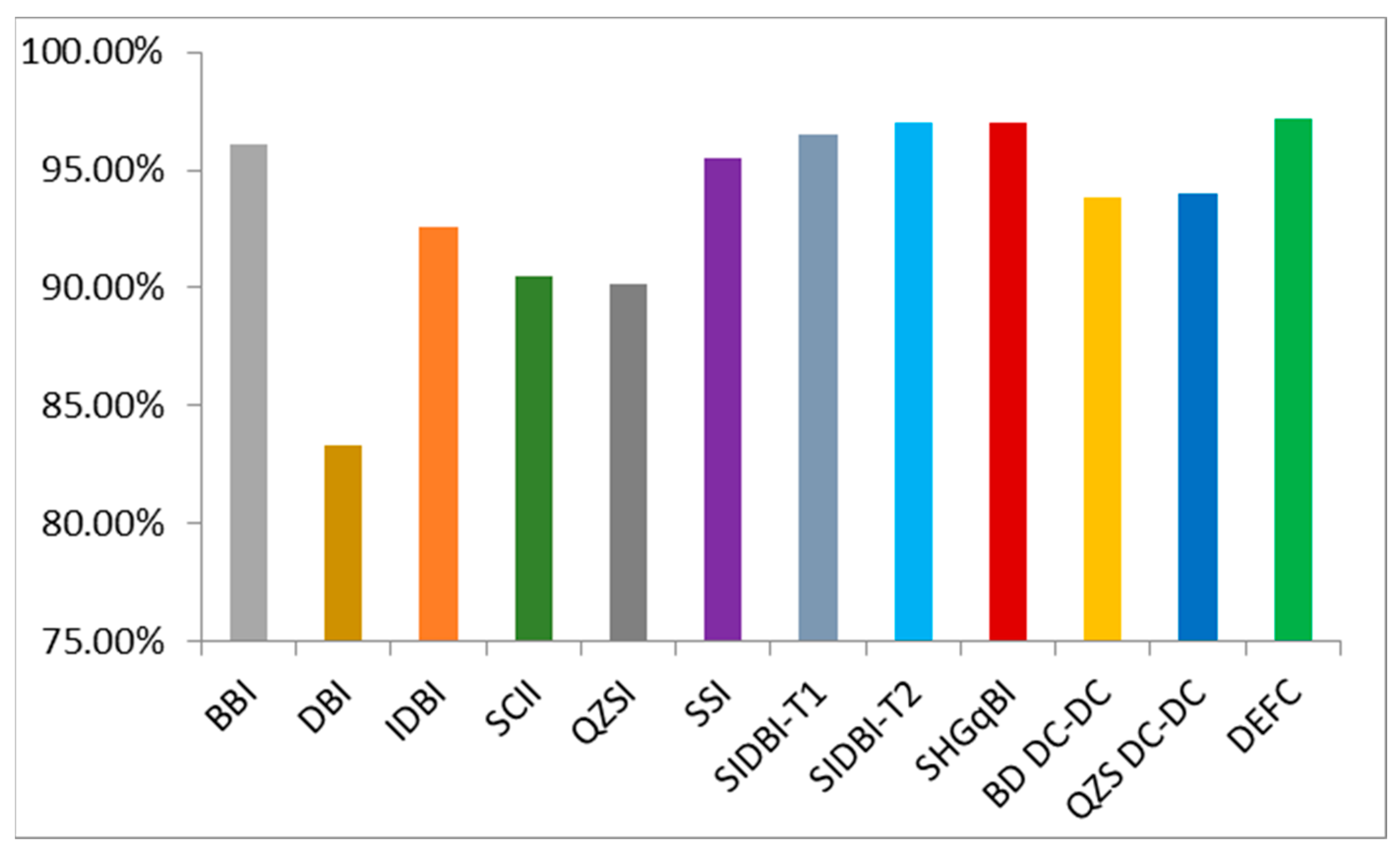
Further, the graphical illustration of the comparative assessment between the proposed and existing converting technique is given in Figure 13. The proposed DEFC is compared with other existing inverters, such as the Differential Boost Inverter (DBI) [24], Quasi Z-Source Inverter (QZSI) [25,26], Buck-Boost Inverter (BBI) [27], Switched-coupled inductor inverter (SCII) [28], Improved Differential Boost Inverter (IDBI) [29], Split-Inductor Differential Boost Inverters Type–I (SIDBI-T1) [30], Split-Source Inverter (SSI) [31], Split-Inductor Differential Boost Inverters Type–II (SIDBI-T2) [30] Simplified High Gain Quasi—Boost Inverter (SHGqBI) [32], Bi-directional DC-DC Converter (BD DC-DC) [11], and Quasi-Z-Source Boost DC-DC Converter (QZS-DC-DC) [21]. From the illustration, it is observed that the proposed DEFC converter attains a higher efficiency rate (more than 97%) and found to be greater than other conventional inverters.
After considering all the above discussion, it is evident that the proposed converter can be utilized in robotic applications and industrial needs as it enhances efficiency and ensures sustainable utilization. However, experimental data may be necessary to calculate the losses associated with motor loads and other parameters. Overall, the performance of the double-ended forward converter depends on several parameters, and proper selection and design of these parameters is critical to ensure efficient and reliable operation of the converter. By carefully considering factors such as capacitive voltage, MOSFET voltage and current, output voltage, and output current, the converter can be optimized for specific applications and provide reliable power conversion with high efficiency.
The proposed method in this study suggests a way to detect the position of permanent magnet stepper motors using only current feedback. By applying Lyapunov stability analysis to micro stepping, the study shows that the measured currents can be interpolated to estimate the approximate position. To analyse the position estimation error during constant velocity, the study examines the position tracking error of micro stepping and proposes a new compensation filter to minimize the error caused by mechanical dynamics. The Heydemann correction and gradient searching methods are used to calibrate the current signals, and 16 phase-shifted sinusoids are employed for current interpolation. Experimental validation confirms the effectiveness of the proposed method. Using the modified double-ended forward converter (DEFC) adapted in this proposed work provides several notable contributions in robotic applications. Some of these contributions include:
  • High Efficiency: The DEFC has high conversion efficiency due to its bi-directional power flow capability and low conduction losses. This makes it an attractive option for powering stepper motors in robotic systems, where energy efficiency is critical;
  • Low Output Ripple: The DEFC has low output ripple due to its transformer-based design, which reduces the effects of parasitic elements such as capacitance and inductance. This feature is important in robotic systems that require precise control of the motor speed and position;
  • Compact Size: The DEFC has a compact size due to its transformer-based design, which reduces the number of components needed for power conversion. This feature is important in robotic systems where space is limited;
  • Improved Control Techniques: The DEFC has led to the development of new control techniques for stepper motor control in robotic systems. In addition, the use of a proportional-integral (PI) control scheme for DEFC-based stepper motor control, which improved the torque control and position accuracy of the system.
Overall, this modified DEFC has made significant contributions to the field of robotic systems by providing an efficient, low-ripple, bi-directional power flow option for controlling stepper motors. Its compact size and improved control techniques make it an attractive option for future robotic applications.

5. Conclusions

In conclusion, the modified double-ended forward converter was modelled in MATLAB platform and the module was implemented for hardware demonstration to evaluate the performance of the proposed converting approach. From the observed results, it was noted that the proposed approach offered high efficient power conversion that can deliver stable and reliable power to a wide range of motor loads. It had an ability to regulate output voltage and current as well as its capability to handle capacitive voltage, make it a popular choice in various applications, including robotic applications for advance industrial needs. The efficiency of the converter was largely dependent on the load parameters, including the load resistance and the switching frequency. Furthermore, the output voltage and current of the converter could be controlled by adjusting the duty cycle and transformer turns ratio, allowing for versatile performance in different needs of motor operation for robotic movements. The input voltage, switching voltage, and output parameters were analysed meticulously, and they ensured the effective operation of the converter for stepper motor load. The stepper motor speed of 450 rad/s was achieved in open-loop with a speed distortion of 10 rad/s. The speed distortions in the motor would cause vibration in robotic arms; a closed-loop PI controller was used to eliminate the speed distortions. From the simulation work, a prototype model of the similar system is done. Overall, the double-ended forward converter is a versatile and efficient power converter that can provide stable and reliable power to a variety of loads, making it a popular choice in modern power electronics.

Author Contributions

Conceptualization, S.N. and R.K.; methodology, S.N. and R.K.; software, S.N.; validation, M.H.A. and F.A.; formal analysis, F.A.; investigation, M.H.A.; writing—original draft preparation, S.N. and R.K.; writing—review and editing, M.H.A. and F.A.; project administration, M.H.A.; funding acquisition, F.A. All authors have read and agreed to the published version of the manuscript.

Funding

This research received no external funding.

Data Availability Statement

No new data were created or analyzed in this study. Data sharing is not applicable to this article.

Acknowledgments

This work was supported by the Researchers Supporting Project (RSPD2023R646), King Saud University, Riyadh, Saudi Arabia.

Conflicts of Interest

The authors declare no conflict of interest.

References

  1. Soltani, S.; Farzanehfard, A.H.; Sabahi, M. Bi-Directional DC-DC Converter for Driving Stepper Motors in Robotics. IEEE Trans. Power Electron. 2016, 31, 3913–3922. [Google Scholar]
  2. Kim, H.; Kwon, Y.; Jung, H.; Lee, J. High-Voltage DC-DC Converter for Driving Large Stepper Motors in Industrial Robotic Applications. IEEE Trans. Ind. Electron. 2017, 64, 548–555. [Google Scholar]
  3. Soltani, S.; Sabahi, M.; Farzanehfard, A.H. A Novel Current-Mode DC-DC Converter for Driving Stepper Motors in Robotics. IEEE Trans. Power Electron. 2017, 32, 6777–6785. [Google Scholar]
  4. Al-Haddad, S.; Ahmad, A.; Dambhare, S. Optimized Double-Ended Forward Converter for Micro-Stepping Motor in Robotic Applications. IEEE Trans. Ind. Electron. 2018, 65, 334–342. [Google Scholar]
  5. Chen, Y.N.; Liang, T.J.; Chen, W.L. Design and Implementation of a Bidirectional Double-Ended Forward Converter for High-Torque Stepper Motors in Robotic Gripper Applications. IEEE Trans. Power Electron. 2019, 34, 626–636. [Google Scholar]
  6. Li, C.; Li, Y.; Li, X.; Gao, J. A double-ended forward converter with primary-side double-pulse modulation and secondary-side synchronous rectification. IEEE Trans. Power Electron. 2021, 36, 799–809. [Google Scholar]
  7. Han, S.; Seo, H.; Cho, B. Soft-switching-based double-ended forward converter with extended duty cycle for high efficiency in light load condition. IEEE Trans. Power Electron. 2021, 36, 5275–5286. [Google Scholar]
  8. Yin, L.; Chen, J.; Liu, Y.; Chen, H. A modified double-ended forward converter with voltage multiplier for low voltage high current applications. IEEE Trans. Power Electron. 2021, 36, 844–856. [Google Scholar]
  9. Zhou, H.; Song, Y.; Cheng, M. A novel dual active bridge converter with improved soft-switching for wide voltage conversion range. IEEE Trans. Ind. Electron. 2020, 67, 10450–10460. [Google Scholar]
  10. Li, B.; Li, X.; Li, H.; Qian, Z. Design and analysis of a wide-output-range high-power-density dual active bridge converter. IEEE Trans. Power Electron. 2021, 36, 7761–7775. [Google Scholar]
  11. Premkumar, M.; Ramakrishnan, C.; Kumar, C.; Sowmya, R.; Sumithira, T.R.; Jangir, P. An Improved Quasi-Z-Source Boost DC-DC Converter Using Single-Stage Switched-Inductor Boosting Technique. Machines 2022, 10, 669. [Google Scholar] [CrossRef]
  12. Yang, Y.; Liu, J.; Chen, Z.; Chen, J. Dual-output double-ended forward converter with LLC resonant tank for renewable energy systems. Int. J. Electr. Power Energy Syst. 2021, 132, 106954. [Google Scholar]
  13. Li, Y.; Li, B.; Li, H.; Li, C.; Li, Y. Dual-output double-ended forward converter with sliding mode control. IET Power Electron. 2021, 14, 511–518. [Google Scholar]
  14. Cho, C.; Cho, H.; Jung, K.; Kim, H. Double-ended forward converter with active clamp reset. IET Power Electron. 2021, 14, 488–497. [Google Scholar]
  15. Zhou, Q.; Xu, Y.; Rasol, J.; Hui, T.; Yuan, C.; Li, F. Reliable Design and Control Implementation of Parallel DC/DC Converter for High Power Charging System. Machines 2022, 10, 1162. [Google Scholar] [CrossRef]
  16. Li, S.; Li, Y.; Li, H.; Li, B. Design of a high-power density double-ended forward converter with current-transformer-assisted active-clamp circuit. IEEE Trans. Power Electron. 2020, 36, 12506–12516. [Google Scholar]
  17. Zhang, Z.; Li, Y.; Li, B.; Li, H.; Li, Y. A novel dual-output double-ended forward converter based on digital control. IEEE Trans. Power Electron. 2020, 35, 8095–8107. [Google Scholar]
  18. Li, Y.; Li, B.; Li, H.; Li, C.; Li, Y. A high-efficiency double-ended forward converter with a novel synchronous rectifier circuit. IEEE Trans. Power Electron. 2020, 35, 12098–12108. [Google Scholar]
  19. Jeong, J.; Kwak, S.; Choi, S. Degradation-Sensitive Control Algorithm Based on Phase Optimization for Interleaved DC–DC Converters. Machines 2023, 11, 624. [Google Scholar] [CrossRef]
  20. Singh, S.; Kumar, A.; Singh, A.K.; Kumar, S. Design and analysis of double-ended forward converter for renewable energy applications. Int. J. Renew. Energy Res. 2019, 9, 667–676. [Google Scholar]
  21. Kumar, K.S.R.; Pandian, A.; Sastry, V.V.; Raveendhra, D. Capacitor Clamped Coupled Inductor Bi-Directional DC-DC Converter with Smooth Starting. Machines 2022, 10, 47. [Google Scholar] [CrossRef]
  22. Alam, M.M.; Salam, M.A. Performance analysis of double-ended forward converter using different magnetics. In Proceedings of the 2019 7th International Conference on the Development of Renewable Energy Technology (ICDRET), Paris, France, 24–26 April 2019; pp. 1–6. [Google Scholar]
  23. Mirzaei, M.; Sabahi, M. Design and simulation of a double-ended forward converter for high-power applications. In Proceedings of the 2019 4th International Conference on Power, Control and Optimization, Ho Chi Minh, Vietnam, 10–13 December 2019; pp. 289–294. [Google Scholar]
  24. Caceres, R.O.; Barbi, I. A boost dc-ac converter: Analysis, design, and experimentation. IEEE Trans. Power Electron. 1999, 14, 134–141. [Google Scholar] [CrossRef]
  25. Anderson, J.; Peng, F.Z. Four quasi-Z-source inverters. In Proceedings of the IEEE Power Electronics Specialists Conference, Rhodes, Greece, 15–19 June 2008; pp. 2743–2749. [Google Scholar]
  26. Nguyen, M.-K.; Lim, Y.-C.; Park, S.-J. A comparison between singlephase quasi-Z-source and quasi-switched boost inverters. IEEE Trans. Ind. Electron. 2015, 62, 6336–6344. [Google Scholar] [CrossRef]
  27. Khan, A.A.; Cha, H. Dual-buck-structured high-reliability and efficiency single-stage buck-boost inverters. IEEE Trans. Ind. Electron. 2018, 65, 3176–3187. [Google Scholar] [CrossRef]
  28. Kim, K.; Cha, H.; Kim, H.-G. A new single-phase switched-coupled inductor DC-AC inverter for photovoltaic systems. IEEE Trans. Power Electron. 2017, 32, 5016–5022. [Google Scholar] [CrossRef]
  29. Tang, Y.; Bai, Y.; Kan, J.; Xu, F. Improved dual boost inverter with half cycle modulation. IEEE Trans. Power Electron. 2017, 32, 7543–7552. [Google Scholar] [CrossRef]
  30. Abdelhakim, A.; Mattavelli, P.; Davari, P.; Blaabjerg, F. Performance Evaluation of the Single-Phase Split-Source Inverter Using an Alternative DC-AC Configuration. IEEE Trans. Ind. Electron. 2018, 65, 363–373. [Google Scholar] [CrossRef] [Green Version]
  31. Khan, A.A.; Lu, Y.W.; Eberle, W.; Wang, L.; Khan, U.A.; Cha, H. Single-Phase Split-Inductor Differential Boost Inverters. IEEE Trans. Power Electron. 2020, 35, 107–120. [Google Scholar] [CrossRef]
  32. Rajalakshmi, M.; Chandramohan, S.; Kannadasan, R.; Alsharif, M.H.; Kim, M.K.; Nebhen, J. Design and Validation of BAT Algorithm-Based Photovoltaic System Using Simplified High Gain Quasi Boost Inverter. Energies 2021, 14, 1086. [Google Scholar] [CrossRef]
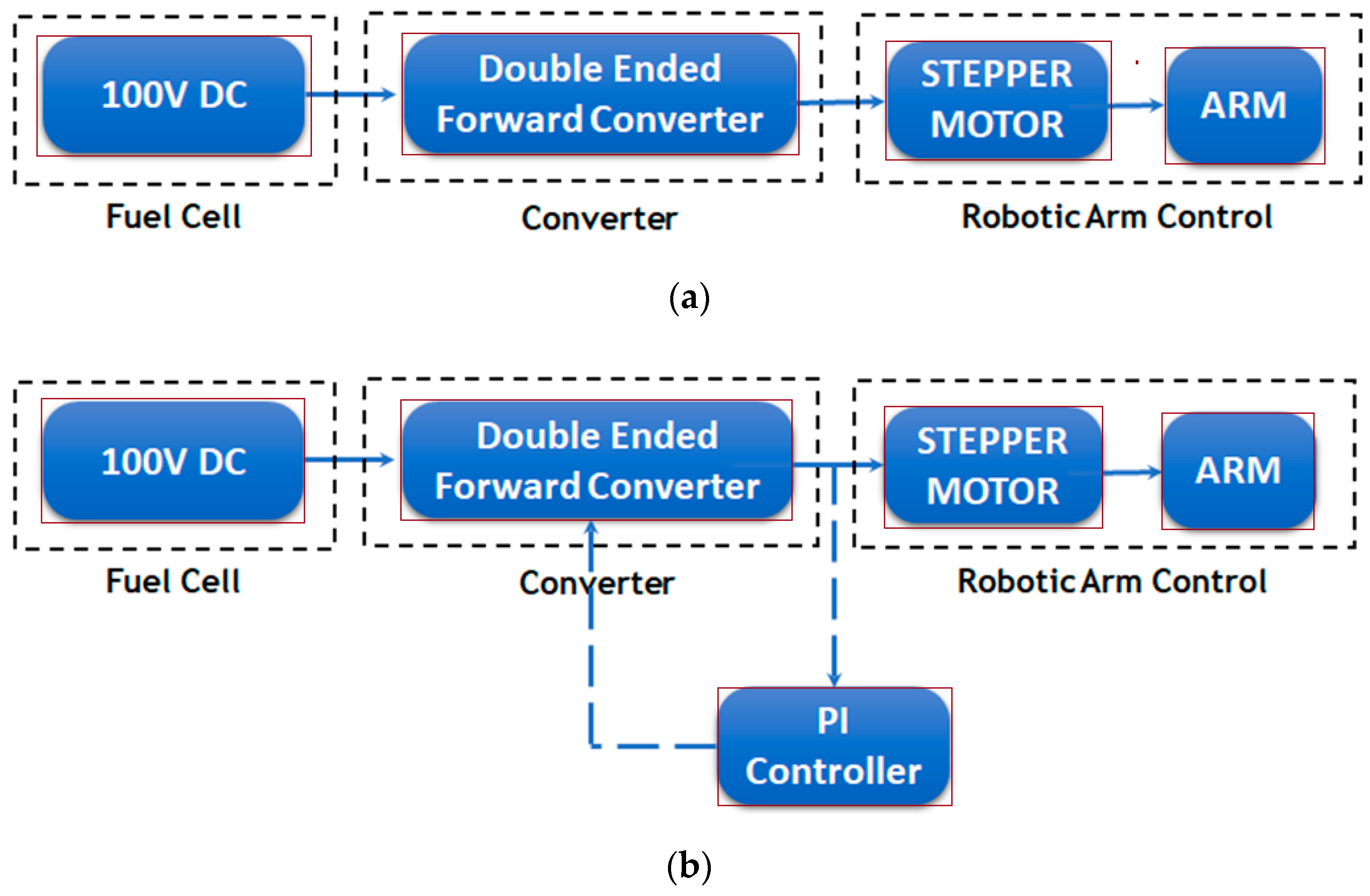
Figure 1. Block Diagram of the Proposed System. (a) Open-loop. (b) Closed-loop.
Machines 11 00777 g001
Figure 2. Proposed model—A Simulink illustration for closed-loop.
Machines 11 00777 g002
Figure 3. Circuit Diagram of the Proposed Method.
Machines 11 00777 g003
Figure 4. Waveform of the converter.
Machines 11 00777 g004
Figure 5. Input voltage and Current for the converter topology. (a) Voltage. (b) Current.
Machines 11 00777 g005
Figure 6. Mutual inductance parameters. (a) Voltage. (b) Current.
Machines 11 00777 g006
Figure 7. MOSFET parameters. (a) Voltage. (b) Current.
Machines 11 00777 g007
Figure 8. Output parameters of the proposed converter. (a) Voltage. (b) Current.
Machines 11 00777 g008aMachines 11 00777 g008b
Figure 9. Stepper motor parameters. (a) Voltage. (b) Current. (c) Torque. (d) Speed.
Machines 11 00777 g009aMachines 11 00777 g009b
Figure 10. Block diagram of the proposed converter.
Machines 11 00777 g010
Figure 11. Hardware prototype.
Machines 11 00777 g011
Figure 12. Hardware results. (a) Input. (b) Output.
Machines 11 00777 g012
Figure 13. Comparison of Converter configurations.
Machines 11 00777 g013
Table 1. Literature Review relating the converter topologies.
TerminologyAdvantagesDisadvantagesAttained OutcomesResearch GapsRef.
Double-Ended Forward Converter with Primary-Side Double-Pulse Modulation and Secondary-Side Synchronous Rectification.Provides isolation between input and output, high efficiency, good for high power applications.More complex circuitry than Flyback converter, output voltage ripple is higher.High power density reduced switching losses, good transient response with 95.5% peak efficiency.Further improvement in efficiency and output voltage regulation under different load conditions.[6]
Soft-Switching-Based Double-Ended Forward Converter with Extended Duty Cycle.It offers high efficiency in light load conditions.It has a more complex circuitry compared to other converters.High efficiency in light load condition with 91.7% peak efficiency.Further research on optimizing the performance under different load conditions.[7]
Modified Double-Ended Forward Converter with Voltage Multiplier.It achieves high efficiency in low voltage high current applications.More complex circuitry than Flyback converter, output voltage ripple is higher.Low voltage high current application with 95.5% peak efficiency.Further optimization of the voltage multiplier circuit for better efficiency and reduced voltage ripple.[8]
Dual Active Bridge ConverterHigh efficiency, high power density, low output ripple voltageComplex control scheme, limited range of output voltageHigh power density, reduced switching losses, good transient responseFurther development of control techniques to achieve higher efficiency at light loads[9,10]
Quasi-Z-Source Boost DC-DC ConverterIt provides an extra voltage gain compared to the traditional
QZS DC-DC converter
Additional capacitor and diode circuit are required.High efficiency with 94.0% peak efficiency.Further research on improving efficiency for motoring load[11]
Double-Ended Forward Converter with LLC Resonant TankProvides isolation between input and output, high efficiency, low voltage ripple, good for high power applicationsMore complex circuitry than other converters, higher costHigh efficiency with 98% peak efficiency, reduced voltage ripple, improved transient responseFurther research on improving efficiency under different load conditions and reducing cost[12]
Dual-Output Double-Ended Forward Converter with Sliding Mode ControlIt offers dual output capability for increased versatility.More complex circuitry than other converters, higher cost, increased number of componentsHigh efficiency with 94.5% peak efficiency, improved transient response, dual output capabilityFurther research on improving the efficiency under light load conditions and reducing cost and complexity[13]
Double-Ended Forward Converter with Active Clamp ResetIt reduces voltage stress for improved efficiency.More complex circuitry than other converters, increased number of componentsHigh efficiency with 97.8% peak efficiency, reduced voltage stress, improved transient responseFurther research on improving the efficiency under different load conditions and reducing cost and complexity[14]
Parallel
DC/DC Converter
It improves the reliability of the charging systemFPGA-based
control techniques are provided which is more complex
No discussion on efficiency enhancement of the proposed systemFurther research on improving efficiency with reduced control strategy required.[15]
Design of a High-Power Density Double-Ended Forward Converter with Current-Transformer-Assisted Active-Clamp CircuitHigh efficiency, high power density, reduced size and weightMore complex circuitry than other converters, increased number of componentsHigh efficiency with 95.8% peak efficiency, high power density of 96.4 W/in3, reduced size and weightFurther research on improving the efficiency under different load conditions and reducing cost and complexity[16]
A Novel Dual-Output Double-Ended Forward Converter Based on Digital ControlIt offers enhanced performance through digital control capabilities.More complex circuitry than other converters, increased number of componentsHigh efficiency with 95.8% peak efficiency, improved transient response, dual output capabilityFurther research on improving the efficiency under light load conditions and reducing cost and complexity[17]
A High-Efficiency Double-Ended Forward Converter with a Novel Synchronous Rectifier CircuitHigh efficiency, reduced voltage stress, good for high power applicationsMore complex circuitry than other converters, increased number of componentsHigh efficiency with 97% peak efficiency, reduced voltage stress, improved transient responseFurther research on improving efficiency under different load conditions and reducing cost[18]
Interleaved DC–DC ConvertersIt reduces the converter’s
output capacitor RMS current
Transistor
degradation imbalance causes an increase in the capacitor RMS current
No discussion on efficiency enhancement of the proposed systemFurther research on improving the efficiency under light load conditions and reducing cost and complexity[19]
Double-Ended Forward Converter for Renewable Energy ApplicationsIt is specifically designed for renewable energy systems, ensuring optimal performance in such applications.More complex circuitry than other converters, increased number of componentsHigh efficiency with 94.6% peak efficiency, improved transient response, good for renewable energy applicationsFurther research on improving efficiency under different load conditions and reducing cost and complexity[20]
Bi-Directional DC-DC
Converter
The clamping capacitor helps in reducing the
ripples in output voltage
More complex circuitry than other converters, increased number of componentsProposed converter achieved efficiency of
93.8%.
Further research on improving efficiency under different load conditions and reducing cost and complexity[21]
Performance Analysis of Double-Ended Forward Converter using Different MagneticsIt achieves high efficiency and reduced voltage stress.More complex circuitry than other converters, increased number of componentsHigh efficiency with 95.4% peak efficiency, reduced voltage stress, good for high power applicationsFurther research on improving efficiency under different load conditions and reducing cost and complexity[22]
Design and Simulation of a Double-Ended Forward Converter for High-Power ApplicationsProvides isolation between input and output, high efficiency, good for high power applicationsMore complex circuitry than other converters, increased number of componentsHigh efficiency with 96.8% peak efficiency, improved transient response, good for high power applicationsFurther research on improving efficiency under different load conditions and reducing cost and complexity[23]
Table 2. Components of the hardware module and their applications.
ComponentsApplications
Power supplyThe power supply provides the input voltage to the converter. It can be a DC power supply or an AC power supply followed by a rectifier and filter.
MOSFETsThe MOSFETs are used as switches in the converter circuit. They are controlled by a driver circuit to switch on and off at a specific frequency and duty cycle.
TransformerThe transformer is used to step down the input voltage to a lower voltage that is suitable for the output load. It consists of a primary winding and one or more secondary windings, and the windings are wound around a magnetic core.
DiodesThe diodes are used to rectify the AC voltage induced in the secondary winding of the transformer, and convert it to a DC voltage that can be used by the output load.
CapacitorsThe capacitors are used to filter the DC voltage and reduce any ripple or noise present in the output.
Output loadThe output load can be any device that requires a regulated DC voltage, such as a motor, LED, or microcontroller. In this work, a stepper motor is considered as the load for robotic applications.
Disclaimer/Publisher’s Note: The statements, opinions and data contained in all publications are solely those of the individual author(s) and contributor(s) and not of MDPI and/or the editor(s). MDPI and/or the editor(s) disclaim responsibility for any injury to people or property resulting from any ideas, methods, instructions or products referred to in the content.