Abstract
Due to their exceptional operational versatility, doubly fed induction machines (DFIM) are widely employed in power systems comprising variable renewable energy-based electrical generation sources, such as wind farms and pumped-storage hydropower plants. However, their starting and grid synchronization methods require numerous maneuvers or additional components, making the process challenging. In this paper, a soft start method for DFIM, inspired by the traditional synchronization method of synchronous machines, is proposed. This method involves matching the frequencies, voltages, and phase angles on both sides of the main circuit breaker, by adjusting the excitation through the controlled power converter at standstill conditions. Once synchronization is achieved, the frequency is gradually reduced to the rated operational levels. This straightforward starting method effectively suppresses large inrush currents and voltage sags. The proposed method has been validated through computer simulations and experimental tests, yielding satisfactory results.
1. Introduction
Addressing environmental challenges is one of the foremost issues in today’s world. They are inherently tied to the adoption of cleaner energy sources for electrical power generation [1,2]. In this regard, wind power and hydropower generation are among the most extensively adopted renewable energy sources worldwide, due to their abundant availability, scalability, and relatively low environmental impact.
In the realm of wind power generation [3,4], doubly fed induction machines (DFIM) technology remains the most widely implemented, as part of the notably known Type-III wind energy conversion systems. Similarly, DFIMs are also predominantly utilized in pumped storage hydropower plants [5,6,7,8,9,10,11,12], where water is pumped or turbined based on demand requirements.
DFIMs play a crucial role in integrating variable renewable energy into the grid [13,14,15], ensuring voltage and frequency controls under varying primary energy inputs, according to applicable regulations. Designed for adjustable speed operation, DFIM systems offer numerous operational advantages, including high energy yield, reduced mechanical stress, low power output fluctuations, and precise control over both active and reactive power.
Typically, DFIM systems are directly grid-connected, featuring a reduced-power converter [16] connected to the rotor that operates at variable frequency. This configuration facilitates the straightforward adjustment of the DFIM’s operating point, to accommodate varying primary energy inputs.
Despite the aforementioned benefits, DFIMs also present certain drawbacks [17,18,19]: being directly grid-connected, they exhibit high sensitivity to external grid faults or disturbances. Additionally, they require regular maintenance due to the wear and tear of slip rings and brushes, and in the case of wind turbines, gearbox maintenance also becomes necessary.
Another significant limitation of DFIMs is their start-up process, extensively addressed in the literature [20,21,22,23,24,25,26,27,28,29,30,31,32,33,34,35,36,37,38,39]. Most of the proposed approaches involve additional elements such as auxiliary power converters and switches to adjust DFIM conditions to the grid, necessitating multiple maneuvers during the start-up process. Consequently, this complexity not only challenges the start-up procedure but also increases the overall cost of electric generation units.
This paper proposes a soft start-up method for DFIMs, based on the synchronization with the power system at standstill conditions. This approach simplifies DFIM starting and eliminates the need for additional components. Analogous to the paralleling of synchronous generators, this technique primarily involves aligning DFIM conditions with those of the grid, and, once achieved, synchronizing with the grid by closing the main circuit breaker (CB) at standstill conditions. Subsequently, using the rotor’s power converter for voltage and frequency control, the machine accelerates to operating speed. This procedure mitigates inrush currents and voltage sags while reducing the complexity of maneuvers and devices required during the start-up process.
This paper is structured as follows: Section 2 provides a brief overview of DFIM start-up procedures. Section 3 describes the proposed start-up method in detail. Section 4 presents computer simulation results for a DFIM start-up using the proposed method. Section 5 reports experimental test results under the same conditions as the simulations, with a discussion of the obtained results. Finally, Section 6 concludes the paper by summarizing its main ideas and contributions.
2. State of the Art
The approaches to DFIM start-up have been classified into four main groups. The main advantages and drawbacks of each of them are summarized in Table 1. In the following, the categories are described based on Figure 1.

Table 1.
DFIM start-up methods: state of the art sum-up.
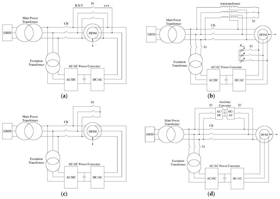
Figure 1.
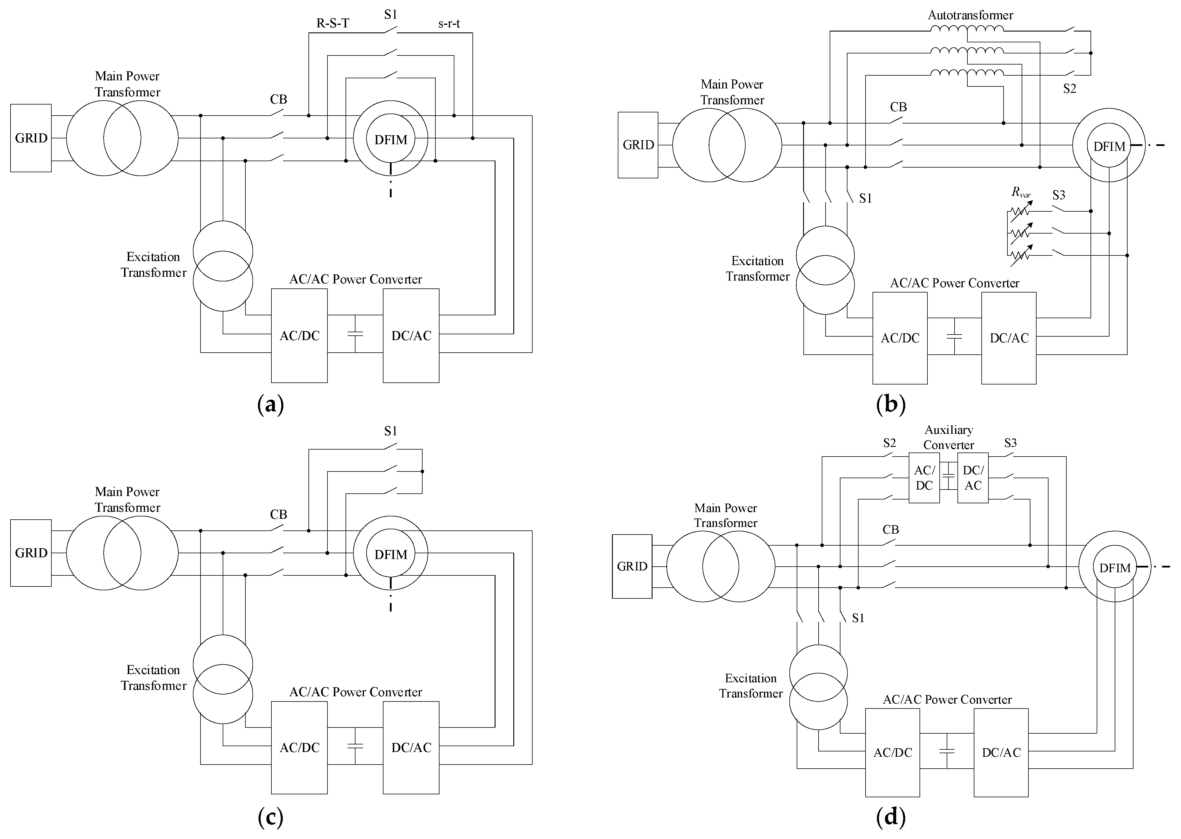
Schemes for DFIM start-up: (a) Opposite phase sequence; (b) Autotransformer and variable resistors; (c) Stator short-circuit; (d) Auxiliary converter.
2.1. Opposite Phase Sequence-Based Start-Up Methods
In these methods, the excitation power converter placed in the rotor of the DFIM and an additional switch (S1, initially closed) is utilized, as illustrated in Figure 1a. The start-up procedure involves feeding both the stator and the rotor of the DFIM through the power converter, with two phases swapped at the connection between the stator and the rotor using S1. Under these conditions, the machine is driven to its rated speed. Then, S1 is opened and the CB connecting the DFIM stator to the power system is closed.
The main advantage of this method is its short starting time [20]. However, the dead time during the commutation between S1 and the CB can induce pulsed torques that may severely damage the machine shaft if synchronization is not achieved shortly after the opening of S1. In [20], these pulsed torques are examined and compared with other methods.
2.2. Reduced Voltage-Based Start-Up Methods
There are various methods to perform a DFIM start-up at low voltage. One approach uses an autotransformer (AT) connected to the stator terminals and a variable resistor (Rvar) in the rotor terminals [21], as shown in Figure 1b. Consequently, two additional switches (S2 and S3, initially closed) are needed to connect and disconnect these elements. The variable resistor enables a progressive start-up. When the motor reaches approximately 95% of its rated speed [22], S2 is disconnected. At this point, the AT functions as a current limiter. Simultaneously, S3 is opened, and S1 is closed, feeding the rotor through the power converter. Finally, the CB is connected, bypassing the AT.
Other techniques rely on the converter to control the variable speed drive, to achieve reduced voltage-based start-up without the need of the AT and the variable resistor [23]. One of the techniques for starting a DFIM at low voltage involves short-circuiting the stator winding [24,25,26,27,28,29,30,31,32,33,34]. This technique is most commonly used for large generator units due to its low pulsed torques and currents. Figure 1c shows the electrical circuit for a stator short-circuit start-up. Only one additional switch (S1, initially closed) is required to perform the short-circuit. First, the rotor converter increases the rotor frequency (fr) up to the rated frequency. Once the DFIM reaches its rated speed, S1 is opened, and after meeting the synchronization conditions, the CB is closed. With this start-up method, the power converter must supply the rotor with a voltage proportional to fr and reduce the voltage as the frequency decreases (constant V/Hz ratio) [24,25]. This ensures that the air gap flux remains constant [24,25,26].
Additionally, the stator short-circuit approach requires fast switching between S1 and the CB, e.g., in [28] this process occurs in 40 ms. Otherwise, the machine and grid conditions may differ significantly, leading to an abrupt grid connection. Several variants of stator short-circuit start-ups exist: using Field Oriented Control (FOC) to accelerate the machine [28,29,30,31,32], applying maximum torque start-up [33], or implementing power loss reduction techniques [34,35]. The dynamic behavior of this approach under converter and sensor faults has also been addressed in previous works [36].
Similarly, the short-circuit can be applied to the rotor winding [23]. In this case, the power converter feeds the stator through an additional switch. The start-up is conducted as if the machine were an ordinary squirrel-cage induction machine-based variable frequency drive. Once synchronization with the grid is achieved, the power converter is disconnected from the stator, which is then fed directly from the grid, and subsequently connected to the rotor [26]. Improvements such as FOC can also be applied in this case [37].
2.3. Auxiliary Converter-Based Start-Up Methods
Auxiliary converter-based start-up methods are softer than the previously presented alternatives, but they require additional electronic devices [32,38,39].
In [38], an auxiliary power converter is installed at the stator terminals to initiate the DFIM operation. The electrical scheme is shown in Figure 1d. Initially, S1, S2, and S3 are closed, allowing the auxiliary converter to feed the stator at the rated frequency. The converter also supplies the rotor to achieve the required rotor speed. Once the operational point is set, the CB is closed under proper synchronization conditions of voltage, frequency, and phase, while the auxiliary power converter remains bypassed. At this point, S2 and S3 are opened, concluding the start-up process. Meanwhile, in [32], the DC bus of the rotor power converter feeds with an additional inverter the machine in the stator and rotor at the same time.
The use of DC/DC converters in the main rotor power converter is another option for synchronizing the machine [39]. When both sides of the DC bus have the same voltage, the DC bus is closed, connecting the grid side converter (GSC) with the rotor side converter (RSC).
2.4. Proposed Start-Up Methods
It is worth noting that all the previously discussed methods require additional elements, such as switches, resistors, or power electronic devices, making their implementation more complex and costlier.
The method proposed in this work solves these issues through a simple synchronization-based approach that reduces complexity and costs. One of the main advantages of this method is that only the main CB is needed for the start-up. Additionally, it retains the benefits of other soft start-up methods, such as avoiding high inrush currents and pulsing torques.
3. Description of the Proposed Soft Start-Up Method
This section describes the theoretical background of the proposed soft start-up method and outlines the steps to implement it (Section 3.1). To this end, the dynamic equations of the DFIM are presented (Section 3.2). Since the present method is based on synchronization to the power system, the conditions on both sides of the switch/CB must be equal in terms of phase sequence, voltage amplitude, frequency, and phase angle. Initially, the DFIM does not rotate unless it is driven by an external torque, because the stator windings are open before synchronization by the time the DFIM is energized through the rotor. This synchronization at standstill conditions is analyzed (Section 3.3). Finally, using the rotor’s power converter voltage/frequency control, the machine is accelerated, which is addressed at the end of this section (Section 3.4).
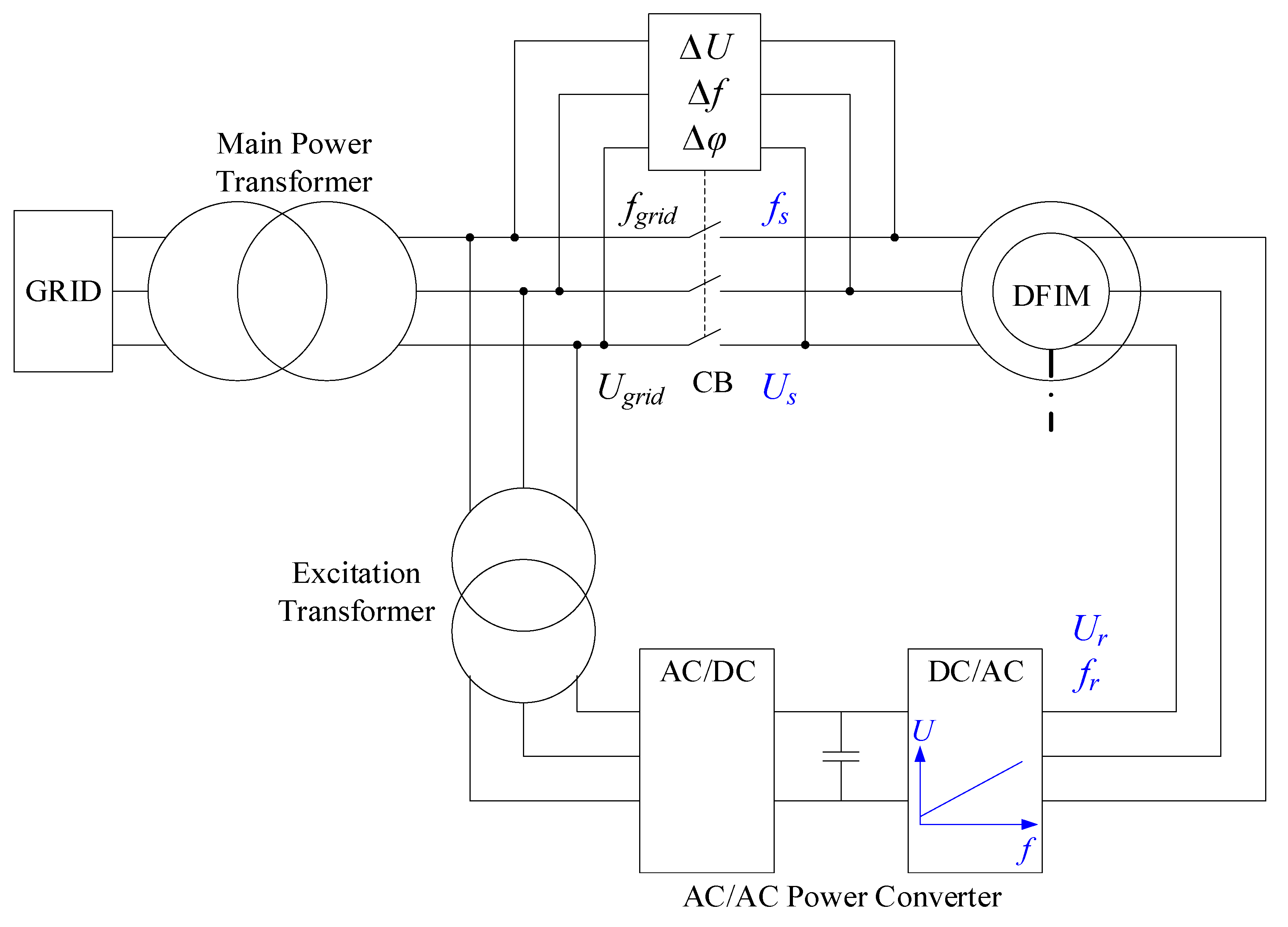
The electrical scheme required for the implementation of the proposed method in pumped storage hydropower plants is shown in Figure 2.
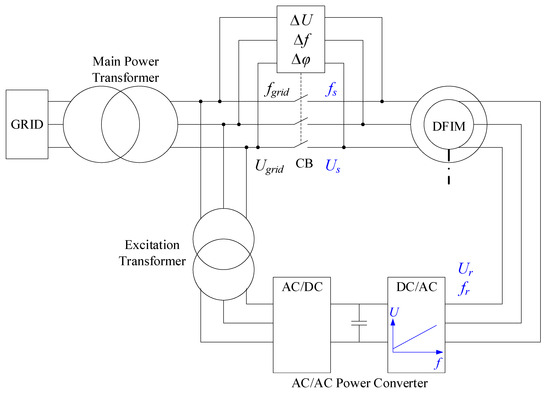
Figure 2.
Electrical scheme for the proposed start-up method [Ugrid: grid voltage; fgrid: grid frequency; Us: stator voltage; fs: stator frequency; Ur: rotor voltage; fr: rotor frequency; ΔU = |Ugrid|−|Us|; Δf = fgrid−fs; Δφ: phase difference between Ugrid and Us phasors].
As shown in Figure 2, the stator of the DFIM is connected to the system through the main power transformer and the main CB, which is equipped with an automatic synchronizing relay. The rotor winding is supplied via two back-to-back converters (grid side and rotor side converters, interfaced by a DC link), powered through an excitation transformer. The shaft is mechanically coupled to the hydro turbine.
3.1. Method Overview
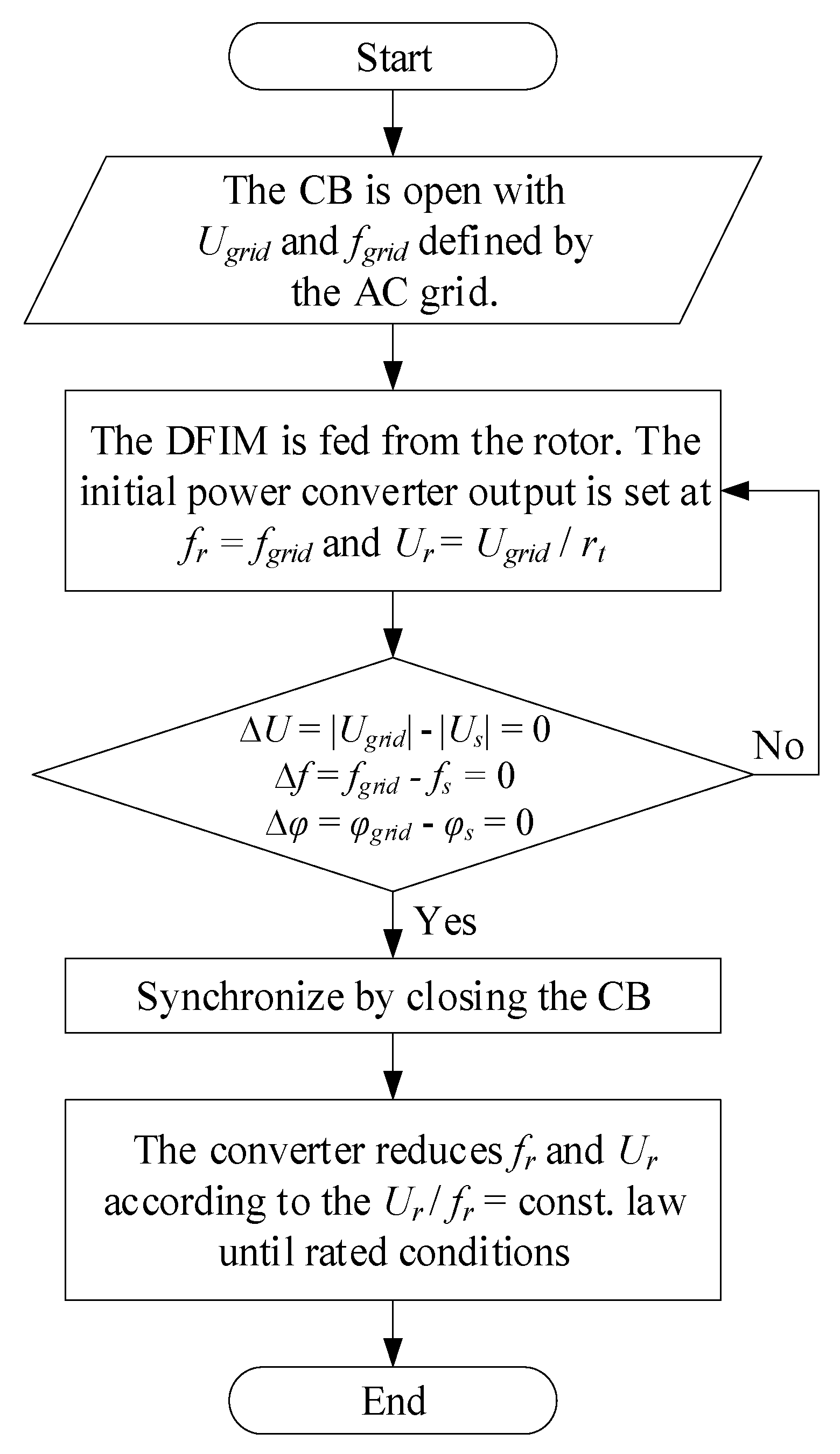
The algorithm that summarizes the start-up process is presented in Figure 3. At the initial conditions, the DFIM is at standstill conditions (zero mechanical speed, ωmec = 0), with the main CB in an open state, i.e., isolated from the grid. In this scenario, grid synchronization conditions must be met.
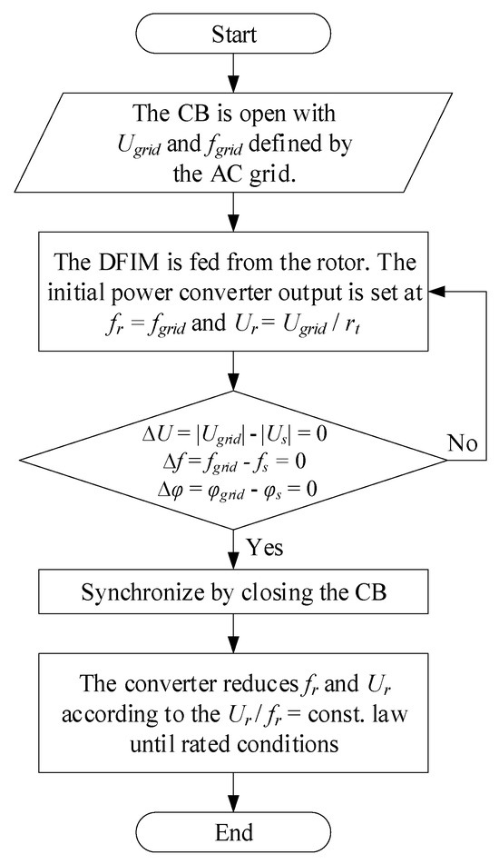
Figure 3.
Conceptual algorithm of the proposed DFIM start-up method.
To achieve the synchronization conditions (voltage amplitude, frequency, and phase angle), the rotor’s power converter must control the voltage frequency and amplitude at its terminals. The frequency of the rotor’s currents should be defined according to Equation (1):
where p is the number of pole pairs of the DFIM, fs is the stator frequency and fr is the rotor frequency.
From Equation (1), it follows that for a start-up from ωmec = 0, the electrical frequency of the rotor (fr) imposed at the terminals of the power converter must be equal to the stator frequency (fs), which is also the grid frequency (fgrid). Furthermore, for a start-up from zero ωmec, which is a common scenario for motor start-ups, the imposed voltage at the power converter terminals must be the rotor rated voltage (Ur) for fr = fs. This ensures that the induced stator voltage (Us) matches the grid voltage (Ugrid) prior to synchronization (Ur = Ugrid/rt, with rt being the rotor/stator voltage ratio). The imposed voltage at the power converter terminals should be controlled under a constant flux strategy. It must be noticed that in the case of turbine start-up mode, i.e., the shaft can be already rotating, fr should be the difference between shaft frequency and fgrid to impose fs = fgrid and then perform the CB closure. The following explanations describe the motor start-up mode, as it is more critical than the turbine one due to the counter torque present in this mode of operation.
Provided that the phase sequence is identical on both sides of the CB, once the converter control has matched the voltage and frequency values with those of the grid (ΔU = |Ugrid|−|Us| = 0 and Δf = fgrid−fs = 0), the breaker (CB) is closed when the phase shift is null (Δφ = 0). The machine is thus synchronized to the grid at standstill conditions. Since the rotor’s frequency is the same as the stator’s, their fluxes are synchronized, preventing the generation of a torque. Consequently, the shaft remains at ωmec = 0 after synchronization.
After synchronization, the power converter gradually reduces its output frequency, causing the shaft to start rotating according to (1). The rotor voltage (Ur) should also be proportionally reduced to maintain the DFIM flux (constant Ur/fr). The starting process concludes once the power converter reaches the rated fr. During this process, the DFIM accelerates from a unitary slip (s) value to the rated s value in a downward ramp progression.
The main advantage of this method over the methods analyzed in Section 2 is that it does not require additional elements such as switches, breakers, autotransformers, variable resistances, or auxiliary converters. Only the main CB is needed. Moreover, the method is characterized by its simplicity and safety, as it avoids any short-circuit conditions. Additionally, inrush currents and voltage sags during start-up are eliminated.
However, despite the benefit of using only the main CB, synchronization conditions must be carefully observed in the stator. Consequently, the high-frequency pulses generated by the power converter, due to pulse width modulation (PWM), will flow through the DFIM during the start-up process. This results in increased electrical insulation stress. Finally, it is important to note that the lower the frequency variation in the power converter, the smoother the start-up will be.
3.2. Dynamic Equations of the DFIM
In order to set up the dynamic equations of a DFIM [40], it is assumed that there is a sinusoidal field distribution along the periphery of the airgap, no zero-sequence currents, and constant saturation throughout the process. In the per unit (p.u.) system, the phasor equations for the stator and rotor are given in the excitation or stator-flux reference frame by Equations (2) and (3), respectively:
where Ψs is the stator flux, Ψr is the rotor flux, ω0 is the angular speed, Rs is the stator resistance, Rr is the rotor resistance, and Is and Ir are the stator and rotor currents, respectively.
The stator and rotor currents and fluxes are related by Equations (4) and (5) as follows:
where Xs is the stator leakage reactance, Xm is the magnetizing reactance and Xr is the rotor leakage reactance of the DFIM.
Substituting Equations (4) and (5) into Equations (2) and (3), the following Equations (6) and (7) are obtained:
Additionally, the mechanical characteristics are expressed by Equations (8) and (9):
where Tm is the mechanical torque, Tr is the mechanical counter-torque in the shaft of the DFIM and H is the rotor inertia constant.
These equations completely define the transient evolution of the machine state variables.
3.3. Stator Synchronization Analysis
The power converter should provide the magnetizing current during the process and should impose the synchronization voltage. Consequently, Is should be zero when closing the CB. According to Equations (6) and (7), Equations (10) and (11) are derived, respectively, as the time derivatives should be null and fr = fs:
This implies that the converter should impose a voltage slightly larger than the rated one. As this is usually not possible, the strategy should be adjusted: Ur will be set at its rated value and its phase angle (φ) should be such that the stator voltage phase angle coincides with Ugrid phase angle (zero phase shift condition). Taking Ugrid as a reference, then, from Equation (6) just before closing the CB:
Introducing Equation (12) into Equation (7), and assuming that Ur = 1 p.u. (with unknown phase angle, φr):
Therefore, the Ir amplitude and the phasor difference between Ugrid and the stator voltage at the synchronization instant are given by Equations (14) and (15), respectively:
Due to the typical values of DFIM parameters, this voltage difference is very small. Thus, the closing transient Is will be also small and lower than its rated value. The initial (just after closing CB) time derivative of Is is expressed by Equation (16):
3.4. DFIM Acceleration
Once the DFIM is synchronized with the grid, it should be accelerated by reducing the magnetizing current provided by the power converter. As a consequence, the power consumption from the grid increases to compensate for this reduction.
To better analyze this process, starting electromagnetic transients shall be neglected. This can be safely completed because the starting is designed to be smooth, i.e., electrical variables will change slowly, and their time (t) decay is fast. So, time derivatives in Equations (6) and (7) will be assumed null. Additionally, to keep the magnetic flux constant, the ratio between Ur and fr will also be constant (Ur/fr = 1 p.u.). Under these assumptions, Ir can be calculated as in Equation (17):
Therefore, Is follows Equation (18):
These equations, along with Equations (8) and (9), allow calculating the machine’s starting dynamics. The acceleration process finalizes when the power converter reaches the rated rotor’s frequency, i.e., the machine slip is reduced from the unitary value to the rated value.
4. Computer Simulations
To validate the proposed method, numerous computer simulations have been performed using Matlab-Simulink® (R2023a). For these simulations, a conventional 0.52-kW DFIM model was considered. In this section, the simulation model and the results of the proposed start-up technique are described.
4.1. Simulation Model
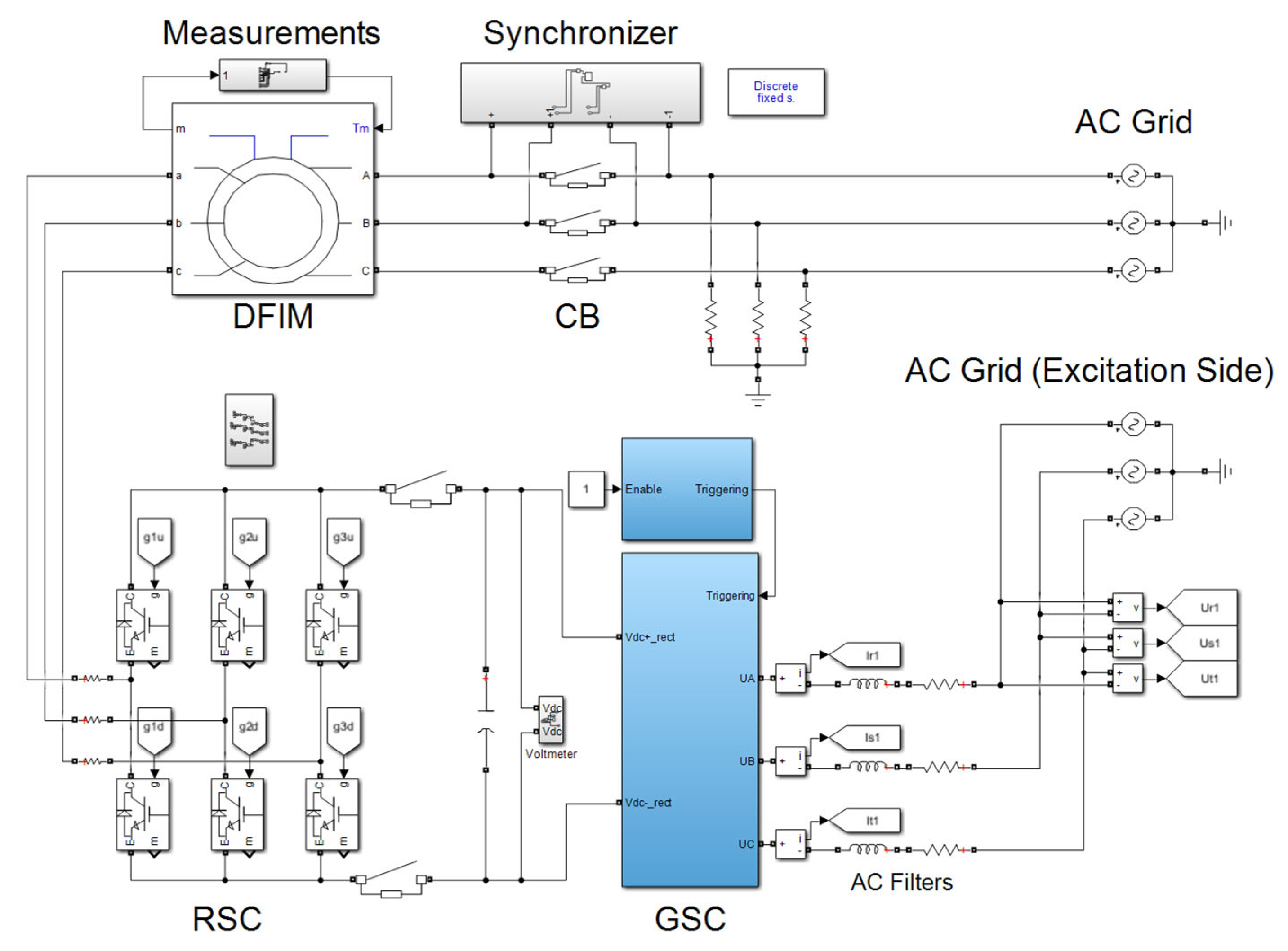
In Figure 4 the simulation model method is shown. Table 2 lists the rated values of the DFIM’s most significant parameters.
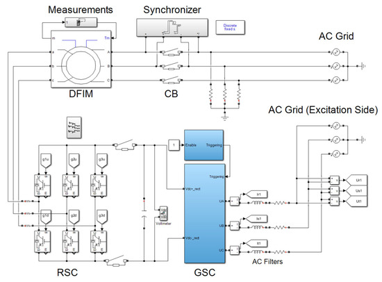
Figure 4.
Simulation model for the stator synchronization-based start-up method.
Table 2.
Simulated DFIM’s main rated parameters.
In this simulation model, the 0.52-kW DFIM is connected to a 400-V, 50-Hz three-phase grid through a CB equipped with a synchronizer. Additionally, high-value resistances have been connected in parallel to the DFIM grid terminals in order to avoid convergence errors during the simulation.
In the rotor circuit, the power converter (fed by a 120-V three-phase grid) is connected in series with a 1-mH choke inductance (equivalent to the secondary of the excitation transformer seen in Figure 2). The grid-side converter is controlled to maintain the voltage at the DC bus (UDC), which employs a 1600-μF capacitor. The setpoint of UDC depends on fr.
On the machine side of the power converter, the inverter generates a PWM signal to obtain the required voltage and frequency at each instant. When starting the machine at standstill conditions, the frequency through the windings is about 49.95 Hz, a value close to the grid’s frequency, allowing for soft synchronization. Once the machine is synchronized, assuming the conditions for voltage, frequency, and phase angle are met, this frequency decreases to about 2 Hz as a downward ramp function. The total acceleration t has been set at 5 s to achieve a soft start-up. If the ramp is too steep, there is a risk of overcurrent due to the DFIM’s moment of inertia (J).
4.2. Results
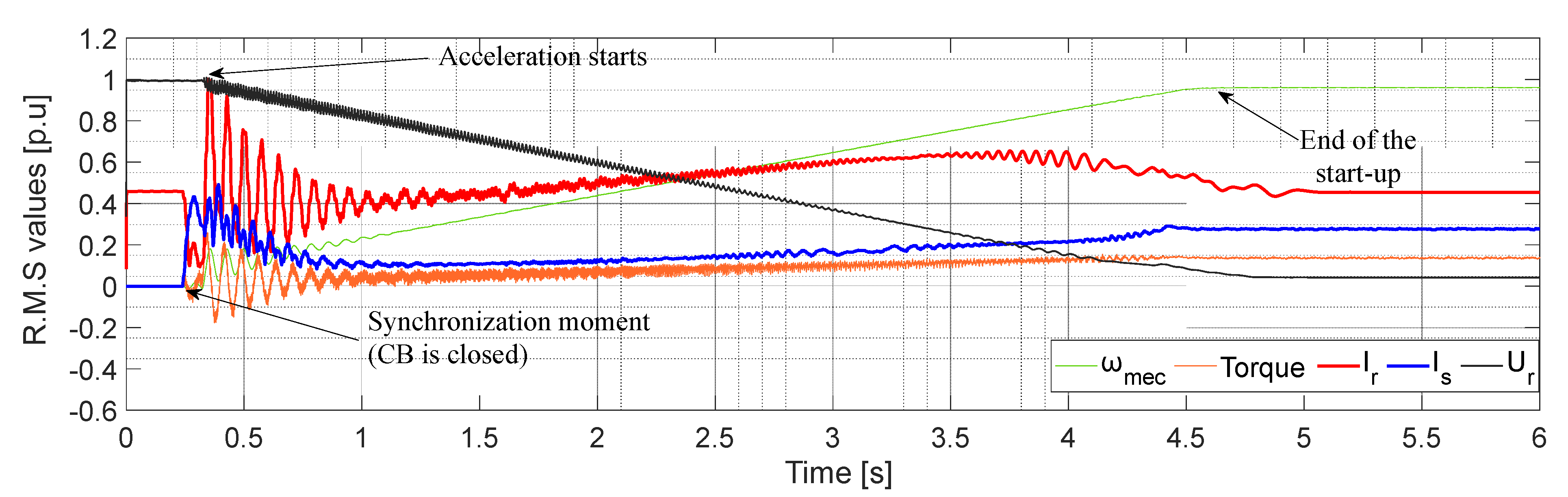
Figure 5 shows the simulation results for the main parameters (ωmec, Tm, Ir, Is, and Ur). All variables are in per unit (p.u.) using DFIM rated values as bases.
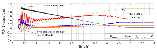
Figure 5.
Simulation results for a stator synchronization start-up [Mechanical rotor speed (ωmec); torque (Tm); RMS values of rotor and stator currents (Ir and Is, respectively); rotor voltage (Ur), in p.u].
In Figure 5, synchronization was achieved at t = 0.242 s. Initially, while the rotor’s current maintained a constant value of 0.45 p.u. to magnetize the DFIM, the stator’s current was zero because the machine was not yet coupled to the grid. On the other hand, Ur was set to obtain Us = Ugrid = 1 p.u on both sides of the CB before synchronization. Once the voltage, frequency, and phase angle conditions were optimal, synchronization was performed.
As shown in Figure 5, after closing the CB, a transient occurred in Is and Ir, while the machine’s shaft remained nearly stationary with negligible torque. The frequency downward ramp was applied at t = 0.3 s. When the frequency slope started at 0.3 s, a larger transient appeared in currents, and consequently in torque, during the first 0.7 s of evolution (up to t = 1 s), as the result of overcoming DFIM inertia. After these transients, the currents and the torque returned to their soft starting state. In this case, both rotor’s and stator’s currents did not exceed 0.5 p.u., except in the initial transient where Ir reached 1 p.u. Once the DFIM was accelerated for approximately 5 s under the constant flux condition, the magnetizing current was proportionally divided into the stator’s and rotor’s currents according to the machine’s impedances. Furthermore, at the beginning Ur and UDC experienced a transient decrease of around 15% and the torque initially pulsed following the current behavior. The acceleration process ends when Ur is brought down to its rated value. Therefore, the DFIM attains its rated speed.
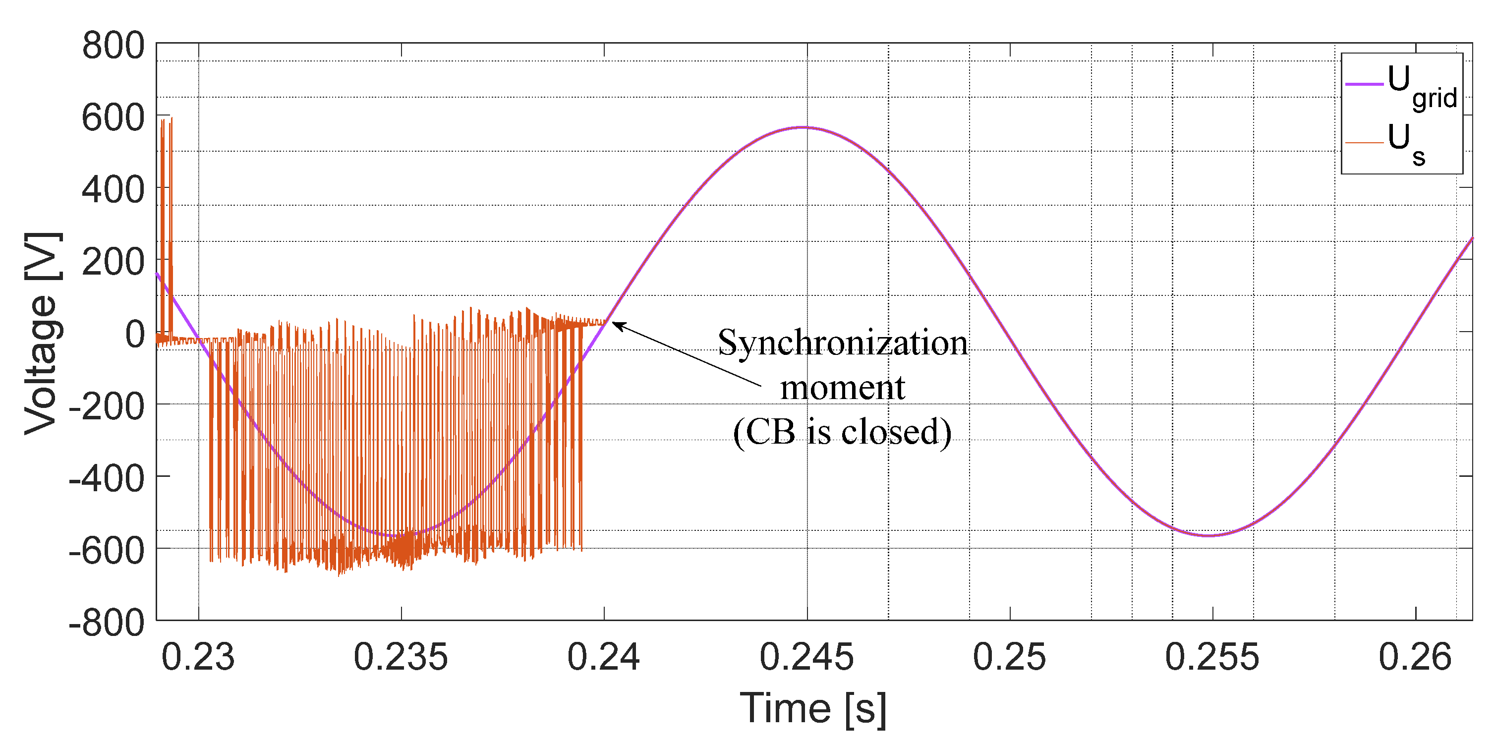
Finally, in Figure 6 the grid and stator voltages are shown. The voltage on both sides of the CB during the synchronization process is plotted. Before the CB was closed, the stator voltage pulsed due to the PWM converter feeding the rotor of the machine. After closing the CB, Ugrid was imposed.
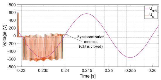
Figure 6.
Grid and stator voltages during synchronization using the proposed DFIM start-up method.
5. Experimental Tests
Obtaining a deeper understanding of the behavior of the previous parameters involved in the start-up process requires thoroughly performed experimental tests. In this section, the experimental setup and the results are described.
5.1. Experimental Setup
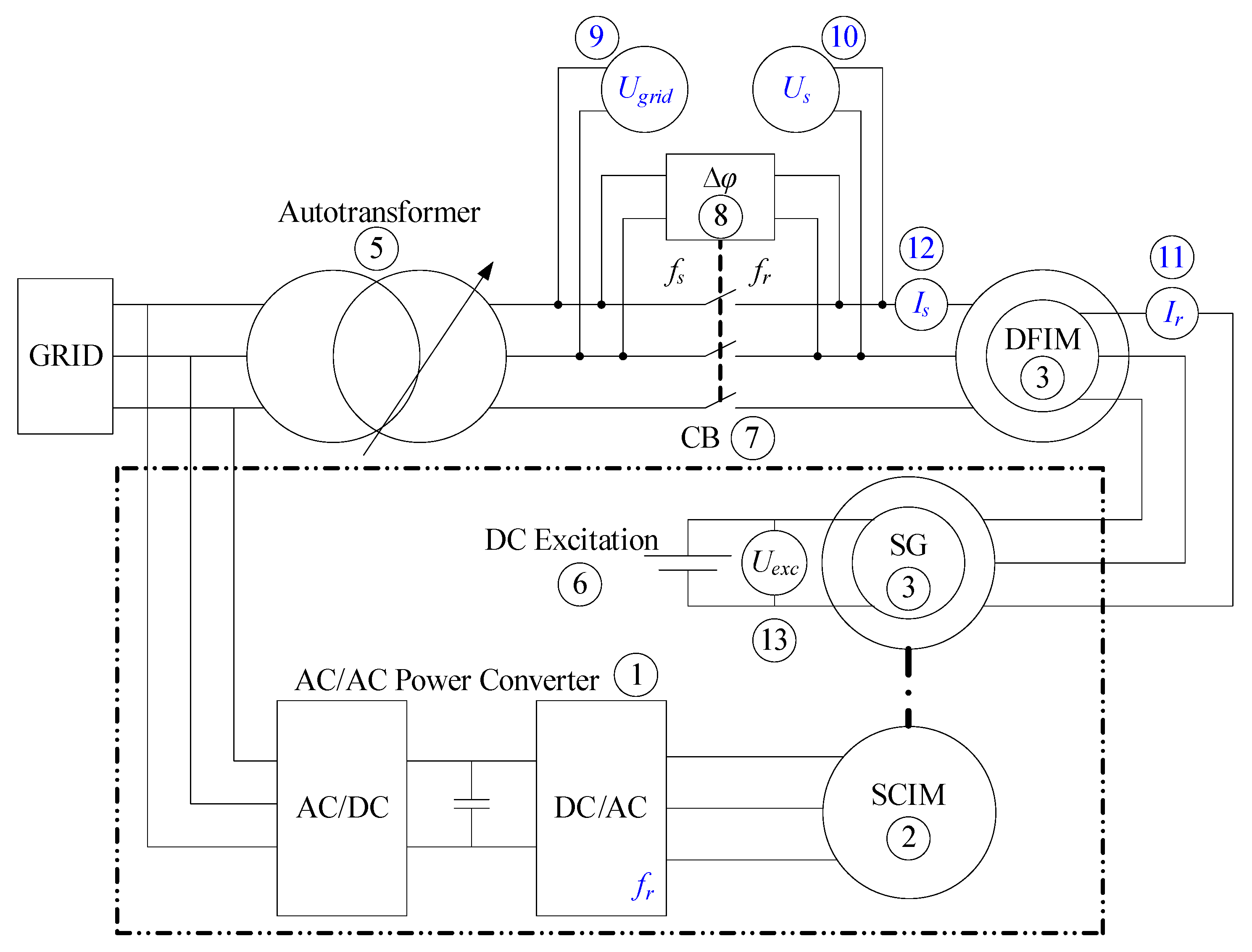
The experimental setup implemented in the laboratory is shown in Figure 7 and Figure 8. It consists of a variable frequency drive (VFD) (1) with a squirrel cage induction machine (SCIM) (2) that drives a synchronous generator (SG) (3). The SG feeds the rotor of a 0.52-kW DFIM (4) with the frequency governed by the SCIM speed and the voltage level controlled by the DC excitation system (6) of the SG. The SG is used to provide constant U/f control for the DFIM rotor’s excitation. However, a controlled power converter could be used instead for rotor feeding in this setup. The DFIM’s nameplate parameters are listed in Table 3 and its equivalent circuit parameters correspond to the ones shown in Table 2.
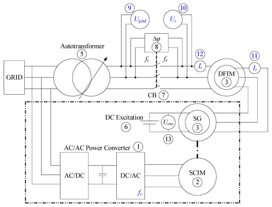
Figure 7.
Experimental setup: electrical scheme [Uexc = Excitation voltage of the SG].
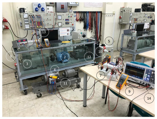
Figure 8.
Experimental setup: overview [(1): VFD; (2): SCIM; (3): SG; (4): DFIM; (5): Autotransformer; (6): DC excitation system; (7): main CB; (8): Synchronoscope; (9) and (10): Voltmeter; (11): Ir measurement; (12): Is measurement; (13): Voltmeter; (14): Oscilloscope].
Table 3.
Tested DFIM’s nameplate parameters.
Therefore, the conditions of fs = fgrid and Us = Ugrid can be easily imposed on the DFIM stator before the closure of the main CB (7). In addition, the voltages can be adjusted using the autotransformer (5) included on the grid side of the CB. With the help of a synchronoscope (8) and two voltmeters (9, 10), the CB is closed when adequate conditions are met.
Furthermore, the rotor and stator currents (11, 12) and voltages are recorded using a 4-channel oscilloscope (14). An additional voltmeter (13) is used to monitor the SG excitation voltage as a safety measure. Once synchronized, the variable speed drive is controlled to decrease the frequency from 50 Hz to 8 Hz and the SG operates under Ur/fr = constant control.
5.2. Results
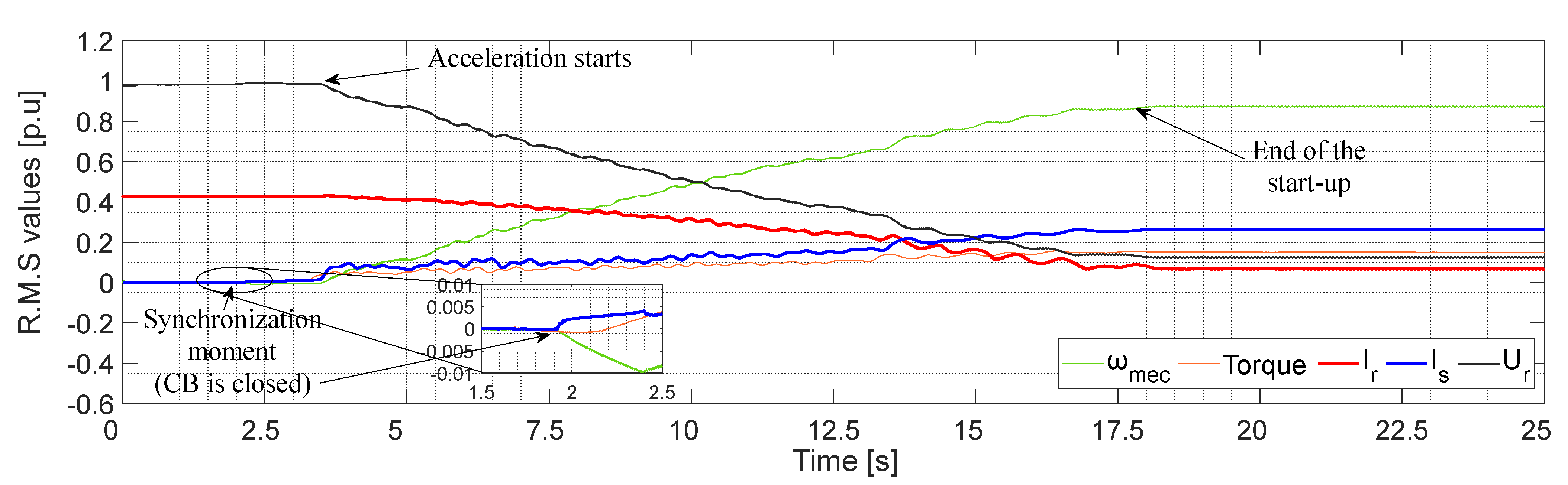
Figure 9 shows the values recorded during a start-up process, which lasts 15 s. The synchronization was performed using two sinusoidal voltage signals because the rotor was fed from an SG.
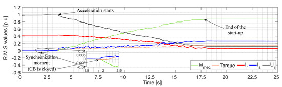
Figure 9.
Experimental results for a stator synchronization start-up [Mechanical rotor speed (ωmec); torque (Tm); RMS values of rotor and stator currents (Ir and Is, respectively); rotor voltage (Ur), in p.u].
As shown in Figure 8, the magnetizing current is provided by the rotor’s feeding at an initial constant value of 0.44 p.u. Once synchronization is performed at t = 2 s, the stator inrush current does not contribute to the DFIM’s magnetization. At t = 3.5, the fr is made to change and the shaft begins its rotational motion. At this point, while the machine is accelerated under the constant flux condition for 14.5 s, the proportion of magnetizing current supported by the stator and rotor varies, as the fr shifts linearly downward from 50 Hz (standstill initial condition) to 8 Hz (final operating point). This causes Ir to decrease and Is to increase.
As the simulation results have also shown, the inrush currents are negligible, and the final currents do not exceed 0.4 p.u. However, the start-up is smoother than in the computer simulations, as the initial transient observed from t = 0.3 to t = 1 s in Figure 5 does not appear in Figure 9. The results shown in Figure 9 suggest that the transient is caused by a simulation discontinuity rather than by a physical phenomenon. Additionally, the torque depicted in Figure 9 does not exhibit the oscillations shown in Figure 5. Thus, the experimental results are consistent with the simulations: before and after synchronization, and throughout the controlled acceleration.
If the start-up current is compared with other techniques found in the literature, it can be observed that it presents one of the lowest values. As the RSC only has to provide the magnetizing current (around 0.4 p.u.), this is the higher reachable value at the start. Meanwhile, opposite phase sequence-based techniques reach around 5–6 times the rated Is [20]. Reduced voltage-based techniques, using autotransformers, reduce up to around 0.8 p.u. the inrush current [21].
Using stator short circuits and, then, performing the synchronization allows obtaining Is = 0.6–1.5 p.u. [25,26,28,29,30,31,32,33,34,35,36], while rotor short circuits reach Is = 1 p.u. during the DFIM start-ups [37]. Finally, the use of auxiliary power converter techniques obtain Is = 0.5 p.u. [39], a value that is in the actual range of the proposed method, and it is an indicator of its viability.
6. Conclusions
This paper proposes a soft start method for DFIM applications. The method feeds the rotor with a frequency equal to the grid frequency, at a standstill and isolated machine conditions, producing the required stator voltage for grid synchronization. Synchronization occurs at standstill conditions through the main CB closure, keeping the rotor still as stator and rotor fluxes are identical, hence no electromotive forces are produced. After synchronization, the rotor frequency and voltage decrease maintaining a constant DFIM flux, gradually increasing the rotor mechanical speed. This enables soft frequency reduction until the desired speed, avoiding high torque transients.
The proposed method stands out from the state-of-the-art because no additional elements are required (switches or breakers, autotransformers, variable resistances, or auxiliary converters, among others). The start-up is achieved using only the main CB and simple converter control. This approach ensures safety by avoiding short-circuit conditions, and it eliminates inrush currents and voltage sags during start-ups.
Computer simulations and experimental tests were conducted for this work. The experimental results are not only consistent with the computer simulations but also demonstrate significant improvements, as some transients observed in the simulations were not present in the experimental measurements. Furthermore, the required currents are substantially lower compared to other start-up methods.
The DFIM start-up method has been validated under free shaft conditions, typical for variable speed hydro reversible generators. However, the main limitation of the method is related to the excitation power converter capacity, because it must be able to introduce the magnetizing current into the rotor up to the synchronization is completed and the rotor frequency starts to decrease. Future works shall aim to adapt the method for loaded start-ups, and also, to overcome this previous limitation by studying alternative DFIM synchronization methodologies that will not utilize the rotor converter to provide the magnetizing current.
Author Contributions
Conceptualization, J.M.G., K.M. and C.A.P.; methodology, J.M.G., I.A., J.G.-C. and C.A.P.; software, J.M.G. and K.M.; validation, J.M.G., K.M. and J.A.S.; formal analysis, K.M. and J.A.S.; investigation, K.M. and C.A.P.; resources, J.M.G. and C.A.P.; data curation, J.M.G. and K.M.; writing—original draft preparation, J.M.G. and K.M.; writing—review and editing, I.A., J.G.-C., J.A.S. and C.A.P.; visualization, J.M.G. and K.M.; supervision, C.A.P.; project administration, C.A.P.; funding acquisition, C.A.P. All authors have read and agreed to the published version of the manuscript.
Funding
This research received no external funding.
Data Availability Statement
Datasets are available on request from the authors.
Conflicts of Interest
The authors declare no conflicts of interest.
Nomenclature and Abbreviations
| fgrid | Grid frequency (in Hz) |
| fr | Rotor frequency (in Hz) |
| fs | Stator frequency (in Hz) |
| H | Rotor inertia constant (in s) |
| Ir | Rotor current (in A) |
| Is | Stator current (in A) |
| J | Moment of inertia (in kg·m2) |
| p | Number of pole pairs |
| Rr | Rotor resistance (in Ω) |
| Rs | Stator resistance (in Ω) |
| rt | Stator/Rotor voltage ratio |
| Rvar | Variable resistance (in Ω) |
| s | Slip |
| Tm | Mechanical torque (in N·m) |
| Tr | Mechanical counter-torque (in N·m) |
| t | Time (in s) |
| UDC | DC bus voltage (in V) |
| Ugrid | Grid voltage (in V) |
| Ur | Rotor voltage (in V) |
| Us | Stator voltage (in V) |
| Xm | Magnetizing reactance (in Ω) |
| Xr | Rotor leakage reactance (in Ω) |
| Xs | Stator leakage reactance (in Ω) |
| φ | Phase angle (in rad) |
| Ψr | Rotor flux (in Wb) |
| Ψs | Stator flux (in Wb) |
| ω0 | Angular speed (in rad/s) |
| ωmec | Mechanical rotor speed (in rad/s) |
| AC | Alternative Current |
| AT | Autotransformer |
| CB | Circuit Breaker |
| DC | Direct Current |
| DFIM | Doubly Fed Induction Machine |
| FOC | Field Oriented Control |
| GSC | Grid Side Converter |
| PWM | Pulse Width Modulation |
| RMS | Root Mean Square |
| RSC | Rotor Side Converter |
| SCIM | Squirrel Cage Induction Machine |
| SG | Synchronous Generator |
| VFD | Variable Frequency Drive |
References
- Khalid, M. Smart Grids and Renewable Energy Systems: Perspectives and Grid Integration Challenges. Energy Strategy Rev. 2024, 51, 101299. [Google Scholar] [CrossRef]
- Wang, X.; Bamisile, O.; Chen, S.; Xu, X.; Luo, S.; Huang, Q.; Hu, W. Decarbonization of China’s Electricity Systems with Hydropower Penetration and Pumped-Hydro Storage: Comparing the Policies with a Techno-Economic Analysis. Renew. Energy 2022, 196, 65–83. [Google Scholar] [CrossRef]
- Bekiroglu, E.; Yazar, M.D. MPPT Control of Grid Connected DFIG at Variable Wind Speed. Energies 2022, 15, 3146. [Google Scholar] [CrossRef]
- Abouloifa, A.; Noussi, K.; Elbouchikhi, E.; Katir, H.; Lachkar, I.; El Aroudi, A. High-Gain Observer-Based Advanced Nonlinear Control of a Grid-Connected Wind Energy Conversion System with Sensorless Maximum Power Point Tracking. Machines 2022, 10, 1074. [Google Scholar] [CrossRef]
- Guo, X.; Yuan, X.; Zhu, D.; Zou, X.; Hu, J. Evaluation and Optimization of DFIG-Based WTs for Constant Inertia as Synchronous Generators. IEEE Trans. Power Electron. 2024, 39, 10453–10464. [Google Scholar] [CrossRef]
- Du, C.; Du, X.; Tong, C.; Li, Y.; Zhou, P. Stability Analysis for DFIG-Based Wind Farm Grid-Connected System Under All Wind Speed Conditions. IEEE Trans. Ind. Appl. 2023, 59, 2430–2445. [Google Scholar] [CrossRef]
- Gao, X.; Xie, Z.; Li, M.; Yang, S.; Zhang, X. Analysis and Mitigation of Electromechanical Oscillations in Drivetrain for Hybrid Synchronization Control of DFIG-Based Wind Turbines. IEEE Trans. Power Electron. 2024, 39, 3002–3013. [Google Scholar] [CrossRef]
- Bidgoli, M.A.; Yang, W.-J.; Ahmadian, A. DFIM versus Synchronous Machine for Variable Speed Pumped Storage Hydropower Plants: A Comparative Evaluation of Technical Performance. Renew. Energy 2020, 159, 72–86. [Google Scholar] [CrossRef]
- Mohale, V.; Chelliah, T.R.; Hote, Y.V. Analysis and Damping of Sub-Synchronous Oscillations in a 250 MW DFIM Hydro Unit Connected to Series Compensated 765 kV Transmission Lines. IEEE Trans. Ind. Appl. 2023, 59, 2234–2245. [Google Scholar] [CrossRef]
- Valavi, M.; Nysveen, A. Variable-Speed Operation of Hydropower Plants: A Look at the Past, Present, and Future. IEEE Ind. Appl. Mag. 2018, 24, 18–27. [Google Scholar] [CrossRef]
- Yang, W.-J.; Yang, J.-D. Advantage of Variable-Speed Pumped Storage Plants for Mitigating Wind Power Variations: Integrated Modelling and Performance Assessment. Appl. Energy 2019, 237, 720–732. [Google Scholar] [CrossRef]
- Lung, J.-K.; Lu, Y.; Hung, W.-L.; Kao, W.-S. Modeling and Dynamic Simulations of Doubly Fed Adjustable-Speed Pumped Storage Units. IEEE Trans. Energy Convers. 2007, 22, 250–258. [Google Scholar] [CrossRef]
- Morfín, O.; Delgado, D.; Campos, A.; Murillo, M.; Hernández, J.I.; Esquivel, P. Fault-Tolerant Controller Applied to a Wind System Using a Doubly Fed Induction Generator. Wind 2024, 4, 90–110. [Google Scholar] [CrossRef]
- Amaro Pinazo, M.; Antara Arias, R.; Mirez Tarrillo, J. Comparison of primary frequency control methods for wind turbines based on the doubly fed induction generator. Wind Eng. 2022, 46, 1923–1947. [Google Scholar] [CrossRef]
- Bahia, K.; Abdelmadjid, B. Stability analysis and study between classical sliding mode control (SMC) and super twisting algorithm (STA) for doubly fed induction generator (DFIG) under wind turbine. Energy 2021, 214, 118871. [Google Scholar]
- Hussain, H.A.; Loncarski, J.; Ristic, L.B.; Bellini, A. DFIG-Based WECS With Partial-Scale Converter: Efficiency, Cost, and Volume Comparison of SiC-Based and IGBT-Based Converter Solutions. IEEE Access 2024, 12, 89908–89920. [Google Scholar] [CrossRef]
- Nnachi, G.U.; Mosetlhe, C.T.; Hamam, Y. A Comparative Power Quality Study of DFIG and PMSG Renewable Energy Conversion Systems. In Proceedings of the 2020 5th International Conference on Renewable Energies for Developing Countries (REDEC), Marrakech, Morocco, 29–30 June 2020; pp. 1–6. [Google Scholar]
- Omodara, P.; Saavalainen, S.; Pitkäaho, E.; Pongrácz, E.; Keiski, R.L. Sustainability Assessment of Products—Case Study of Wind Turbine Generator Types. Environ. Impact Assess. Rev. 2023, 98, 106943. [Google Scholar] [CrossRef]
- Ntuli, W.K.; Kabeya, M.; Moloi, K. Review of Low Voltage Ride-Through Capabilities in Wind Energy Conversion System. Energies 2024, 17, 5321. [Google Scholar] [CrossRef]
- Hamouda, R.M.; Alolah, A.I.; Badr, M.A.; Abdel-Halim, M.A. A Comparative Study on the Starting Methods of Three Phase Wound-Rotor Induction Motors. I. IEEE Trans. Energy Convers. 1999, 14, 918–922. [Google Scholar] [CrossRef]
- Zhang, Y.; Ooi, B.T. Adapting DFIGs for Doubly-Fed Induction Motors Operation. In Proceedings of the 2012 IEEE Power and Energy Society General Meeting, San Diego, CA, USA, 22–26 July 2012; pp. 1–8. [Google Scholar]
- IEEE Std 1010-2022 (Revision of IEEE Std 1010-2006); IEEE Guide for Control of Hydroelectric Power Plants. IEEE: New York, NY, USA, 2023; pp. 1–95.
- Yuan, X.; Chai, J.; Li, Y. A Converter-Based Starting Method and Speed Control of Doubly Fed Induction Machine With Centrifugal Loads. IEEE Trans. Ind. Appl. 2011, 47, 1409–1418. [Google Scholar] [CrossRef]
- Joseph, A.; Selvaraj, R.; Chelliah, T.R.; Sarma, S.V.A. Starting and Braking of a Large Variable Speed Hydrogenerating Unit Subjected to Converter and Sensor Faults. IEEE Trans. Ind. Appl. 2018, 54, 3372–3382. [Google Scholar] [CrossRef]
- Joseph, A.; Desingu, K.; Semwal, R.R.; Chelliah, T.R.; Khare, D. Dynamic Performance of Pumping Mode of 250 MW Variable Speed Hydro-Generating Unit Subjected to Power and Control Circuit Faults. IEEE Trans. Energy Convers. 2018, 33, 430–441. [Google Scholar] [CrossRef]
- Saiju, R.; Koutnik, J.; Krueger, K. Dynamic Analysis of Start-Up Strategies of AC Excited Double Fed Induction Machine for Pumped Storage Power Plant. In Proceedings of the 2009 13th European Conference on Power Electronics and Applications, Barcelona, Spain, 8–10 September 2009; pp. 1–8. [Google Scholar]
- Gong, G.; Lv, J.; Jiang, X.; Sun, X. Grid-Connection Control of Doubly Fed Variable Speed Pumped Storage Unit. In Proceedings of the 2021 5th International Conference on Green Energy and Applications (ICGEA), Singapore, 6–8 March 2021; pp. 52–57. [Google Scholar]
- Rauth, S.S.; Kastha, D.; Bajpai, P.A. Sensorless control strategy for automatic start-up and grid-synchronization of doubly fed induction generator in wind energy conversion system. Int. J. Circ. Theor. Appl. 2024, 52, 1733–1753. [Google Scholar] [CrossRef]
- Pannatier, Y.; Kawkabani, B.; Nicolet, C.; Schwery, A.; Simond, J.-J. Optimization of the Start-Up Time of a Variable Speed Pump-Turbine Unit in Pumping Mode. In Proceedings of the 2012 XXth International Conference on Electrical Machines, Marseille, France, 2–5 September 2012; pp. 2126–2132. [Google Scholar]
- Pannatier, Y.; Kawkabani, B.; Nicolet, C.; Schwery, A.; Simond, J.-J. Start-Up and Synchronization of a Variable Speed Pump-Turbine Unit in Pumping Mode. In Proceedings of the XIX International Conference on Electrical Machines—ICEM 2010, Rome, Italy, 6–8 September 2010; pp. 1–6. [Google Scholar]
- Li, D.; Gong, G.; Lv, J.; Jiang, X.; He, R. An Overall Control of Doubly Fed Variable Speed Pumped Storage Unit in Pumping Mode. In Proceedings of the 2020 IEEE 4th Conference on Energy Internet and Energy System Integration, Wuhan, China, 30 October–1 November 2020; pp. 3709–3714. [Google Scholar]
- Malathy, N.; Sukhi, Y. Improved Start-Up Strategy for a Doubly Fed Induction Machine Fed Large Rated Variable Speed Pumped Storage Unit in Pumping Mode Operation. Electr. Eng. 2023, 106, 615–629. [Google Scholar] [CrossRef]
- Maendly, T.; Hodder, A.; Kawkabani, B. Start-Up of a Varspeed Group in Pump Mode: Practical Implementations and Tests. In Proceedings of the 2016 XXII International Conference on Electrical Machines (ICEM), Lausanne, Switzerland, 4–7 September 2016; pp. 1201–1207. [Google Scholar]
- Singh, R.R.; Baranidharan, M.; Subramaniam, U.; Bhaskar, M.S.; Rangarajan, S.S.; Abdelsalam, H.A.; Collins, E.R.; Senjyu, T. An Energy-Efficient Start-Up Strategy for Large Variable Speed Hydro Pump Turbine Equipped with Doubly Fed Asynchronous Machine. Energies 2022, 15, 3138. [Google Scholar] [CrossRef]
- Singh, R.R.; Chelliah, T.R. Energy Saving Start-Up Strategy of Pumped Storage Power Plant Equipped with Doubly-Fed Asynchronous Machine. In Proceedings of the 2016 IEEE 1st International Conference on Power Electronics, Intelligent Control and Energy Systems (ICPEICES), Delhi, India, 4–6 July 2016; pp. 1–6. [Google Scholar]
- Anto, J.; Chelliah, T.R. Starting Performance of Doubly Fed Induction Machine Drive Serving Pumped Storage Plants Subjected to Faults in Power and Control Circuits. In Proceedings of the 2016 IEEE 1st International Conference on Power Electronics, Intelligent Control and Energy Systems (ICPEICES), Delhi, India, 4–6 July 2016; pp. 1–7. [Google Scholar]
- Narayanasamy, M.; Sukhi, Y. Rotor Short-Circuited Start-Up Strategy for a Doubly Fed Induction Machine-Fed Large-Rated Variable-Speed Pumped Storage Unit Operating in Pumping Mode. J. Power Electron. 2023, 23, 1733–1744. [Google Scholar] [CrossRef]
- Pérez-Díaz, J.I.; Cavazzini, G.; Blázquez, F.; Platero, C.; Fraile-Ardanuy, J.; Sánchez, J.A.; Chazarra, M. Technological Developments for Pumped-Hydro Energy Storage; Technical Report, Mechanical Storage Subprogramme, Joint Programme on Energy Storage; European Energy Research Alliance: Brussels, Belgium, 2014; Available online: https://www.eera-energystorage.eu/ (accessed on 21 November 2024).
- Ghodbane-Cherif, M.; Skander-Mustapha, S.; Slama-Belkhodja, I. Start-Up System Design for Small Scale Autonomous DFIG Wind Turbine. Wind Eng. 2021, 45, 753–768. [Google Scholar] [CrossRef]
- Kovács, P.K. Transient Phenomena in Electrical Machines; Studies in Electrical and Electronic Engineering; Elsevier: Amsterdam, The Netherlands, 1984. [Google Scholar]

Disclaimer/Publisher’s Note: The statements, opinions and data contained in all publications are solely those of the individual author(s) and contributor(s) and not of MDPI and/or the editor(s). MDPI and/or the editor(s) disclaim responsibility for any injury to people or property resulting from any ideas, methods, instructions or products referred to in the content. |
© 2024 by the authors. Licensee MDPI, Basel, Switzerland. This article is an open access article distributed under the terms and conditions of the Creative Commons Attribution (CC BY) license (https://creativecommons.org/licenses/by/4.0/).