Abstract
Milling parts with low rigidity (thin-walled parts) are increasingly attracting the interest of the academic and industrial environment, due to the applicability of these components in industrial sectors of strategic interest at the international level in the aerospace industry, nuclear industry, defense industry, automotive industry, etc. Their low rigidity and constantly changing strength during machining lead on the one hand to instability of the cutting process and on the other hand to part deformation. Solving both types of problems (dynamic and static) must be preceded by prediction of cutting forces as accurately as possible, as they have a significant meaning for machining condition identification and process performance evaluation. Since there are plenty of papers dealing with this topic in the literature, the current research attempts to summarize the models used for prediction of force in milling of thin-walled parts and to identify which are the trends in addressing this issue from the perspective of intelligent production systems.
1. Introduction
Parts with low rigidity (flexible parts) obtained by milling are components with a compact structure and low weight due to the removal by the machining process of a significant amount of the workpiece’s material (up to 95%) [1], obtaining a “buy-to-fly” ratio (i.e., the ratio between the weight of the workpiece and the weight of the finished part) up to 30:1 (Figure 1) [2,3]. A more common expression used to define them is the ratio between the height (H) of the workpiece’s wall and the wall thickness (t), according to which the optimal machining strategy is chosen. This ratio can be small (H:t < 15:1), medium (15:1 < H:t < 30:1), and high (H:t > 30:1) [4,5]. Generally, parts whose thickness varies between 1 and 2.5 mm are considered parts with low rigidity [6].

Figure 1.
Types of parts with low rigidity. (a) rib; (b) T parts; (c) impeller and (d) blisk [2,3]; (e) sealing cover and (f) fuselage panel [2].
In recent years, the growing interest in machining flexible parts, both in academic and industrial environments (Figure 2), has been linked to their large applicability in various industrial sectors, especially in the aerospace and automotive industries [7,8], being generally made from advanced materials specifically developed for these industries, such as aluminum and titanium alloys (both separately and in combination, e.g., titanium aluminides TiAl) [9,10], nickel-based alloys (e.g., Inconel 718 [11,12], Inconel 625 [13]), various stainless steels (e.g., austenitic stainless steel [14,15], martensitic stainless steel [16]) etc. The special properties of these materials (i.e., high specific strength, low weight, corrosion resistance, etc.) make it possible to reduce the amount of material needed to obtain the desired components, offering a good weight-to-strength ratio [17].
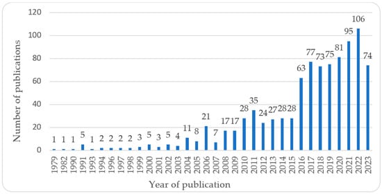
Figure 2.
Publications in the Web of Science database addressing milling of parts with low rigidity (of which 710 are articles and 223 are proceeding papers; search performed by using “thin-wall milling” keywords on 24 November 2023).
However, milling of flexible parts is quite problematic because they have low rigidity (the thickness of the parts is at least six times smaller than the other two dimensions) and consequently are very easily deformed during the machining process. This leads to increased geometric errors, making it quite difficult to ensure the machining quality of these components [18,19]. Induced residual stresses can also change their final geometry such that different strategies need to be implemented to control [20,21] or compensate their effect on part deformation [22,23]. In addition, due to the low rigidity, forced and self-induced vibrations (“chatter” phenomenon) occur during machining [24,25], leading to changes at the tool–workpiece interface. This causes modifications to chip width, which in turn affects the cutting forces. Such instability leads on the one hand to the appearance of unevenness on the workpiece’s surface and implicitly to an increase in the roughness of the machined surface, adversely affecting the quality of the finished part, and on the other hand to significant wear of tools and even of machine-tool components [26,27]. Moreover, a continuous change in material properties may occur during machining [28,29], which is very difficult to predict or anticipate and therefore to control.
Thus, when milling flexible parts, their low rigidity and constantly changing strength lead on the one hand to the instability of the machining process, and on the other hand to part deformation, which inherently limits production quality and efficiency. Accurate prediction of cutting force is necessary before solving both dynamic and static problems [30] (Figure 3).

Figure 3.
Specific problems when milling parts with low rigidity.
Since there are plenty of papers dealing with this topic in the specialty literature, the current research attempts to summarize the models used for force prediction in milling of thin-walled parts and identify the trends in addressing this issue from the perspective of intelligent production systems. The findings of this research can serve as a background for new theoretical and experimental studies that bring advanced knowledge and solve specific industrial challenges in the field of machining thin-walled components.
2. Models for Cutting Force Prediction When Milling Parts with Low Rigidity
Cutting force directly affects parts’ deformation and integrity of the machined surfaces, as it is influenced by various parameters such as tool geometry and material, workpiece material, milling method, and machining regime (e.g., cutting depth, cutting speed, feed rate, lubrication mode) [31,32]. Therefore, cutting force prediction plays an important role in choosing process parameters and tool geometry to obtain an appropriate quality of the finished part and high productivity, which in turn results in lower production costs.
However, machining prediction is like weather forecasting, as a scientist once said [33]: there is always a certain degree of uncertainty because the models are only abstractions of reality, and they will never be able to fully imitate reality. From this perspective, two ways of addressing the issue of force prediction when milling parts with low rigidity can be identified in the specialty literature: the “traditional” approach, where the basic idea is that known inputs plus an accurate model lead to the desired outputs, and the “modern” approach, where the “uncertain/ignored” reality (the gap between model prediction and the real behavior of the system) is treated from data (known inputs) and manipulated by artificial intelligence in real time, improving the model capability for making faster and more accurate predictions (e.g., digital and hybrid twin systems).
2.1. The Traditional Approach of Force Prediction
Different models have been proposed by researchers for the estimation of cutting force in milling parts with low rigidity, with varying degrees of finesse concerning their accuracy and applicability, as a result of an industrial necessity but also as a scientific challenge [34]. They can be broadly divided into three generic categories: empirical models, mechanistic models, and numerical models.
2.1.1. Empirical Models
Empirical models constitute the traditional experimental approach for estimating and relating the machining performance to different influencing process variables for each individual machining operation [35,36]. In the particular case of milling force prediction, empirical models are expressed as polynomial regression equations, where the cutting force is calculated as a function of the main process parameters (e.g., Equation (1), Table 1), such as cutting speed, feed rate, and cutting depth [37], as well as tool geometry (tool diameter, number of flutes on the milling cutter, etc.) [38,39]:
where νc is the milling speed, fz represents the feed rate, ap is the axial cutting depth, ae is the radial cutting depth, d stands for tool diameter, z denotes the number of flutes on the milling cutter, C, kf, x1 − xn represent coefficients or exponents that are specific to each tool–workpiece material combination, and consequently, a significant number of experimental tests are necessary to determine them and enhance the accuracy of the fitting model [6,37,40].

Table 1.
Empirical models for cutting force prediction in milling parts with low rigidity.
As can be seen, the empirical models ignore the real cutting mechanism and the material removal process. Besides, as already mentioned in the previous section, when machining parts with low rigidity, deformation of the part occurs, which influences the cutting force. Empirical force prediction models do not take this interaction into account. They do not consider vibration (chatter) that occurs during machining either, which is why more complex models have been necessary with higher accuracy in estimating the cutting force. However, despite these drawbacks and the fact that they have a low degree of predictability, empirical models are very well suited for creating optimization strategies for low-rigidity part milling parameters to make the milling process more efficient.
2.1.2. Mechanistic Models
Unlike the empirical models, the mechanistic approach for cutting force prediction is based on real cutting mechanics, so it takes into account not only machining parameters but also chip formation [44], tool–workpiece contact [45,46], cutting tool geometry (e.g., different helix angles [47], different serrated shapes of the cutting edge [48], helical inserted cutters [49,50]), tool and workpiece materials [4,51], system deflection [23,24,52,53] and vibration [54,55], tool runout [56,57,58], tool wear [59] and so on. The mechanistic force models are the most widely used in the analysis of the milling process of parts with low rigidity.
In the modeling process, the cutting edge of a tool is treated as both integral and discretized. As the ball-end milling cutters are usually used for machining parts with low rigidity [60,61,62], many models address the cutting behavior of a ball-end mill whose cutting edge is discretized into a finite number of elements along the axial direction. The differential cutting forces acting on each elemental cutting edge are then calculated based on the oblique cutting mechanism according to the methodology developed in [50,63] (Figure 4). The approach assumes that the instantaneous cutting forces are proportional to the uncut chip area through different empirical coefficients that capture, separately, the effect of the two fundamental mechanisms of cutting process: rubbing or ploughing at the cutting edge (the interference of the tool flank with the machined workpiece surface) and cutting due to shearing at the shear zone and friction at the rake face (Equation (2)):
where , and are the elemental tangential, radial, and axial cutting forces acting on flute j of an ideal system (i.e., with a rigid cutter and zero eccentricity in the cutter axis of rotation), , and are the edge force coefficients, , , and represent the cutting force coefficients, is the instantaneous uncut chip thickness ( is the feed rate per tooth and is the instantaneous immersion or orientation angle of the reference flute j), denotes the thickness of each discrete element, and is the length of each discrete element along the cutting edge.
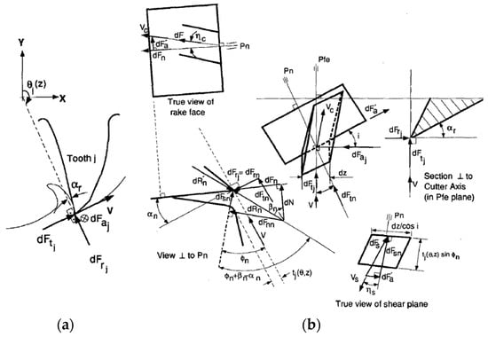
Figure 4.
Modeling of milling forces: (a) The elemental cutting forces acting on flute j of an ideal system; (b) oblique cutting model for a milling tooth element [63].
By integrating the above relations along the in-cut portion of a flute j, the instantaneous cutting forces acting on the flute in feed (x), normal (y), and axial (z) directions can be calculated [64] (Equation (3)):
where and are the lower and upper axial engagement limits of the in-cut portion of the flute.
As more than one flute is simultaneously engaged in cutting during milling, the contribution of all flutes is considered to calculate the total instantaneous forces on the cutter at immersion θ [50,63,64,65] (Equation (4)):
where z is the number of flutes on the milling cutter. Obviously, if a flute j is out of the immersion zone, its contribution to the total forces is null.
Finally, the instantaneous resultant cutting force acting on the milling cutter can be calculated as [64] (Equation (5)):
The prediction accuracy of cutting forces depends largely on the reliability of cutting force coefficients (CFCs) determination. The specialty literature depicts two approaches to addressing this issue. One of them is the unified mechanism approach, which relies on experimentally established orthogonal cutting databases, and the process-dependent CFCs are analytically obtained by applying the classical oblique transformation model [50,63,66,67] (Equation (6)):
where τ is the workpiece’s material shear stress, , , and i are the tool’s normal rake angle, friction angle at the rake face and helix angle, respectively, and are the normal shear and friction angles in oblique cutting, respectively, and and are the chip length ratio and chip flow angle in the rake face, respectively.
Similarly, the edge force coefficients , and can be determined from the orthogonal cutting database values for the appropriate tool–workpiece pair and cutting conditions. In view of this, a comprehensive set of orthogonal cutting tests at different cutting depths, rake angles, and cutting speeds needs to be performed and measuring the force components along and perpendicular to the cutting speed direction as well as the chip length ratio or chip thickness ratio [63].
The other option for CFC calculation is the direct calibration approach, which uses measured milling forces and determines average or instantaneous cutting force coefficients as a function of the uncut average chip thickness [68,69] or instantaneous uncut chip thickness at the tool–workpiece interface, respectively [51,67,70,71,72]. The former models, known as “lumped-mechanism force models,” combine the effects of the shearing mechanism on the tool’s rake face and the ploughing mechanism on the tool’s flank face into one specific force coefficient for each cutting force component along the tangential, radial, and axial directions [73,74]. These coefficients are treated as constants [75,76,77] or function of the average uncut chip thickness [78]. However, even if the average uncut chip thickness is unchanged, the instantaneous uncut chip thickness varies frequently and significantly during the milling process due to part and tool geometry, runout parameters, cutter deflection, etc. [79,80], so some prediction accuracy is lost. Consequently, later models, known as “dual mechanism force models,” consider CFCs as varying parameters depending upon the instantaneous uncut chip thickness and use two coefficients to characterize independently the effect of shearing and ploughing mechanisms (i.e., specific cutting and edge force coefficients). These coefficients can either be predicted from the mechanics theory of general oblique cutting, based on an orthogonal database for given tool–work material pairs, or experimentally determined from cutting tests, when the orthogonal database is not available or the tool has complex geometry [61,75,81,82]. The cutting force coefficients defined by the instantaneous uncut chip thickness allow for a significantly more accurate prediction of cutting forces than those based on the average chip thickness [83,84].
To sum up, the determination of cutting forces using mechanistic models involves the steps presented in Figure 5.
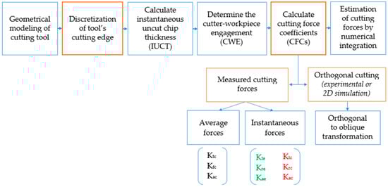
Figure 5.
Mechanistic model stages for cutting force determination.
In the thin-walled milling process, due to parts’ low rigidity, deformation is an unavoidable phenomenon under the action of cutting force [85,86] that leads to low machining accuracy (i.e., serious surface-dimensional errors [87]), repeated machining, and even scrap parts that negatively impact the production efficiency [88]. Therefore, to establish a cutting force model that fits the actual machining, the deformation–cutting force relationship has to be taken into consideration [89,90]. This implies including in the force model the instantaneous immersion boundaries of the tool–workpiece contact zone [28,90,91]. However, this is quite a complicated issue because the cutting forces in machining thin-walled parts depend on the instantaneous uncut chip thickness, which is a function of the tool immersion angle [92]. The immersion angle of the tool is in turn a function of part deflection [93], which itself depends on the cutting forces. Therefore, to solve this complex dependency, an interactive approach needs to be applied that links force prediction with part deflection modeling [73,94]. The algorithm’s accuracy and efficiency can be further improved by considering not only mechanically induced workpiece deformation but even thermal deformation, especially in the case of milling difficult-to-cut materials characterized by high strength and low thermal conductivity [59].
When milling thin-walled parts, not only the parts deform under the machining load but also the cutting tool. As such, a cantilever beam theory is usually used to calculate tool deflection, which is then incorporated into force predictive models separately [79,86,87,95,96,97] or simultaneously with workpiece deflection and immersion angle variation for calculating the instantaneous uncut chip thickness and cutting force coefficients [89,91,92,93]. In such approaches, some authors have treated the tool–workpiece deformation as static [98,99], while others proposed dynamic models, which also considered the relative tool–workpiece displacement when computing the instantaneous chip thickness [52,55,100] (Equation (7)):
where is the quasi-static deformation related to the rigid body motions between tool and workpiece and is the dynamic component associated with the relative vibrations between tool and workpiece.
Besides tool and workpiece deflections, tool runout (mainly caused by the misalignment of tool-holder assembly and spindle axes) also affects cutting force [57,101]. Since in ball-end milling, the tool’s diameter is usually small, only the radial runout has a significant influence on cutting force in that it results in a periodic changing of instantaneous uncut chip thickness [102,103]. The presence of tool runout redistributes the instantaneous uncut chip thickness as well as the cutting forces [104,105]. Therefore, consideration of tool runout should be a must when developing force prediction models, since it exists in practice and the assumption of no runout may not provide an accurate model [106,107]. In fact, it was shown that tool radial runout has a significant influence on cutting forces, both in quantitative and qualitative terms [108,109], and good agreement of the predicted cutting forces with the values from the validation experiments is obtained when it is part of the model [72,86,93,110,111].
To get even closer to real machining conditions and increase the practical application value of force prediction models, tool wear is another critical issue that needs to be considered [112,113]. In industrial practice, exploring the relationship between tool wear propagation and cutting force variation is an indirect method for tool wear monitoring in real-time applications [114,115]. Knowing this dependency in the case of milling thin-walled parts is very important, as tool wear has severe effects on the quality and efficiency of the machining process, especially for hard-to-cut materials [116,117]. According to published literature, under the condition of tool wear, additional cutting loads have a significant influence on the tool–workpiece interaction [118]. Also, it has been shown that cutting forces are very sensitive with increased flank wear [119,120], and there is a direct correlation between the increase in cutting force components and the flank wear width [58,121,122]. Low deviations between the measured and calculated cutting forces (e.g., within the range of 5% to 14% for a worn tool and 2% to 7% for a sharp tool [59]) demonstrate the reliability and robustness of the prediction models that include tool wear as a parameter.
For complex parts such as turbine blades, integral impellers, blisks, etc., five-axis end milling has become widely used owing to its capacity to avoid interference between tools and workpieces and to achieve higher precision and efficiency [123,124]. Providing two additional degrees of freedom compared with traditional three-axis milling, five-axis milling machines offer many advantages, including better tool accessibility, a faster material removal rate, and an improved surface finish [19,39,125,126].
However, the prediction of cutting force in five-axis milling of thin-walled parts has become complicated and is still a challenge because of difficulties in determining the undeformed chip thickness and the geometric complexity [127,128,129]. To solve these issues, the influence of curvatures of the in-process workpiece surface and the real tool’s motion analysis (i.e., continuous variations of tool axis orientation [130], tool path curvature and torsion [131,132], varying feed rate [133], and cutting speed [134]) on chip formation needs to be incorporated into the cutting force prediction models [130,135]. The undeformed chip thickness must be calculated according to the real kinematic trajectory of the tool under a continuous change in tool axis orientation [136,137]. Variation in part geometry and tool orientation along the tool path leads to changes in the tool–workpiece engagement boundaries [138,139] that in turn change the chip distribution. Cutting forces are greatly affected by the distribution of chip thickness along the cutting edge, which is in contact with the workpiece [140,141]. It was shown that neglecting the effect of the geometrical shape of the workpiece surface (WS) around the cutting region on the tool–workpiece engagement (CWE) can lead to an error of up to 50% in the prediction of resultant cutting force acting on the tool [142]. Therefore, recent studies in the literature proposed different approaches for predicting cutting forces in five-axis milling of thin-walled components accurately and efficiently, which essentially consist of the following stages: first, describe the tool spatial motion considering all geometrical features of the WS, then calculate the instantaneous uncut chip thickness and determine CWE boundaries, and finally, based on CFCs experimentally determined, predict the cutting forces and validate the model [143,144,145].
2.1.3. Numerical Models
Numerical models are an alternative to the costly, tedious, and time-consuming experimental approach of the thin-walled part-machining process. Reviewed literature revealed that among simulation techniques, the finite element method (FEM) is mostly used to solve process-specific issues such as prediction of force and force-induced deformations [146,147], study of residual stresses and their effect on part accuracy [148,149,150], optimization of the workpiece clamping system [21,151,152], and study of cutting temperature and its effect on part integrity [153], etc.
In terms of cutting force prediction, few research articles dedicated explicitly to this topic have been reported in the literature, and they are mainly focused on studying the effects of machining parameters, tool geometry, tool deflection and workpiece material on cutting forces, but also on stress distribution, cutting temperature, part deflection, and chip morphology [154,155]. In addition, a numerical model was developed in [156] to obtain the specific force coefficients for a mechanistic model as an alternative to the experimental tests (Table 2).
Some other works studied cutting force as a source of in-process deflection and deformation [157,158,159], residual stress state [160,161], and vibrations of parts with low rigidity [162,163].
To be effective, numerical models need to be accurate and fast—the two main engineering objectives of all time. However, these two words are not very compatible in reality: accuracy achievement is extensively time-consuming because of the huge computation burden, and on the other hand, when a very fast process is needed, the model should be simplified, which in principle means lower accuracy. Consequently, depending on the targeted objective, some of the proposed models are simpler, based on idealized part geometries (e.g., cantilever beam), a simple representation of the cutting tool (e.g., a cylinder), and many simplifying assumptions (e.g., simulating the milling of a single tool tooth, rigid cutting tool, workpiece stable elastic deformation, etc.), while others try to be more realistic representations of the thin-wall milling physical process, considering real tool shape, tool–workpiece deflection, tool–workpiece dynamic interaction, etc. In the case of the latter models, in order to reduce the simulation time, different solutions have been implemented, such as adapted meshing technology (i.e., refined mesh at the tool–workpiece interface and a larger mesh for the rest of the model) [164,165], stiffness matrix reduction [166], or the use of alternative simulation methods (e.g., finite cell method, FCM), which can preserve accurate physical domain information without requiring a dense mesh and a huge accompanying global stiffness matrix (reduced the computing time by nearly 19 times [167]). Even so, numerical models are limited in reproducing the actual cutting conditions while ensuring accurate real-time results.
Table 2.
Numerical models for cutting force prediction in milling parts with low rigidity.
Table 2.
Numerical models for cutting force prediction in milling parts with low rigidity.
| Reference | Method | Software | Main Work | Material/Constitutive Model | Element Types |
|---|---|---|---|---|---|
| The effects of process parameters on cutting forces | |||||
| [39] | FEM | ABAQUS | Effects of n, fz, ap, ae, d, γ, λ, z on cutting forces and deformations | TC4 (DIN3.7164/5)/ Johnson–Cook | T: solid carbide rigid body WP: linear explicit elements |
| [156] | FEM | AdvantEdge | Determination of specific cutting force coefficients | AISI 4340 steel/ N/S | T and WP: N/S |
| [164] | FEM | ABAQUS | Study of stress field, temperature field, cutting force, and workpiece deformation by considering coupling effect of strain hardening rate and temperature | Ti-6Al-4V alloy/ modified Johnson–Cook + VUMAT subroutine | T and WP: C3D4T four node thermal coupling tetrahedral elements |
| [168] | FEM | ABAQUS | Effects of tool’s helix angle on cutting forces and deformations | 2024-T351 alloy/ Johnson–Cook | T: solid carbide rigid body WP: C3D8R brick elements |
| [169] | FEM | N/S | Effect of clamping system on cutting forces and part deformation | Al6061 alloy/ Johnson–Cook | T: cemented carbide rigid body; WP: N/S |
| [170] | FEM | DEFORM-3D | Effects of tool’s inclination angle on cutting forces and chip formation morphologies | Ti-6Al-4V alloy/ Johnson–Cook | T: cemented carbide rigid body; WP: tetrahedral elements, adaptive mesh |
| [171] | FEM | AdvantEdge | Effects of tool’s inclination angle on cutting forces | Al7075 alloy/ Johnson–Cook | T: cemented carbide YG8 rigid body; WP: N/S |
| [172] | FEM | ABAQUS | Effects of process parameters on cutting forces, stress distribution, cutting temperature, part deflection and chip morphology | 2024-T351 alloy/ Johnson–Cook | T: solid carbide rigid body WP: C3D8R brick elements |
| [173] | FEM | DEFORM-3D | Study of cutting forces, cutting temperature, thermal stress field | Cr12MoV multi-hardened steel/ Johnson–Cook | T: solid carbide ball-end mill rigid body; WP: plastic body, adaptive mesh |
| The effect of cutting forces on deformation/residual stress/vibration of parts | |||||
| [23] | FEM | ABAQUS/3D model | Effect of milling strategy on part distortion Identification of precontrol compensation techniques by considering MIRS and IBRS | 7050-T74 alloy 7050-T7451 alloy/ N/S | T: N/S WP: C3D8R brick elements, adaptive mesh |
| [148] | FEM | AdvantEdge | Influence of cutting force on residual stresses | Al 7050-T451 alloy/ N/S | T: horniness alloy; WP: N/S |
| [160] | FEM | ABAQUS | Influence of cutting force and heat on residual stress generation | Al2024 alloy/ Johnson–Cook | N/S |
| [161] | FEM | ABAQUS | Prediction of surface residual stress | Ti-6Al-4V alloy/ Johnson–Cook | T: solid carbide ball-end mill rigid body WP: C3D4T 4-node thermal coupling tetrahedral elements, adaptive mesh |
| [165] | FEM | SolidWorks Plug-ins | Influence of cutting force on stress distribution and stress variation trends | Ti-6Al-4V alloy/ N/S | T: N/S; WP: 4-node 3D solid mesh, adaptive mesh |
| [166] | FEM | N/S | Cutting force-induced error prediction using stiffness matrix reduction | 6061 alloy/ N/S | T: cantilevered elastic beam WP: 3 mesh densities. |
| [167] | FCM | MATLAB/ FCMLab | Prediction of deformation errors | 6061 alloy/ Voxel model | T: solid carbide ball-end mill, rigid body WP: cells mesh |
| [174] | FEM | LS-DYNA | Cutting force-induced error prediction | 2A12 aluminum alloy N/S | T: cantilevered elastic beam, tetrahedral elements WP: hexahedral elements. |
| [175] | FEM | ABAQUS | Effect of geometry constraints on parts’ deformation and deflection | 2024-T351 alloy/ Johnson–Cook | T: R3D4 elements, rigid body; WP: C3D8R solid elements, adaptive mesh |
| [176] | FEM | N/S | Prediction of parts’ deflection | Ti-6Al-4V alloy/ N/S | T: tetrahedron solid element rigid body; WP: tetrahedron solid element, adaptive mesh |
| [177] | FEM | ANSYS | Prediction of parts’ deflection and elastic–plastic deformations | Al-7075 alloy/ N/S | T: rigid body; WP: 8-nodes thermal SOLID-70 and structural SOLID-45 brick elements, adaptive mesh. |
T—tool; WP—workpiece; γ—tool’s rake angle; λ—tilt angle, respectively; MIRS/IBRS—machining-induced/initial bulk residual stresses, respectively; N/S—not specified.
2.2. The Modern Approach of Force Prediction
To sum up, the traditional approach to force prediction when milling parts with low rigidity operated first with mathematical models that are representations of the process reality by using equations, from simpler (e.g., empirical models) to complex, with many more parameters considered (e.g., mechanistic models). When these nominal physics-based models, with their associated nominal loads and calibration data, became too complex, to solve them accurately and quickly, the switch was made to the use of simulation (i.e., numerical models) and based on the computer-identified solutions, the prediction of performance was evaluated.
However, the extensive physical testing that provided the confidence needed to assure the models’ reliability has become increasingly expensive to perform (in terms of time, labor, and material consumption). On the other hand, numerical models have limited predictive capability because they only produce responses that have previously been observed experimentally and then programmed for future assessments. Meanwhile, the milling process is inherently nonlinear and time-varying, even under normal operating conditions. Especially in low-rigidity part machining, the workpiece geometry and stiffness continue to change throughout the process, and as was shown in the previous sections, variations in cutting force are often unavoidable. Therefore, considering this changeable operating environment and finding ways to counteract its consequences on process performance in real time has become an imperative and a focus of many research studies.
2.2.1. Adaptive Control Techniques
Various control strategies have been proposed to maintain constant cutting force during low-rigidity part machining. Adaptive control technology has been widely used for online machining monitoring and instantaneous intervention in the process. An important part of most adaptive control schemes is the online parameter identifier, or adaptive law, which generates estimates of the unknown parameters to be used for calculating or updating the controller parameter in real time [178]. Thus, adaptive control can estimate the process model online and adjust the control parameters accordingly to meet the desired system performance. In terms of the milling process, this means that it can adapt to time-varying machining conditions and adjust the machining parameters (e.g., feed rate, spindle speed) to maintain a constant level of the cutting force.
Early studies implemented different schemes of identifier-based adaptive control, such as indirect [179,180] and direct adaptive control [123,181,182] and model reference adaptive control (MRAC) [183,184,185], but due to their dependence on a certain machine setup, they found limited applicability in real industrial environments characterized by changeable machining conditions (i.e., different tools, different workpieces, different lubricants, etc.). Therefore, some robust adaptive control solutions, which involve using tiny feedback around the adaptive law’s pure integrator, were proposed to maintain a constant cutting force in the presence of parametric uncertainty for a time-varying process [184,186]. However, the applicability of these controllers has also been limited because they assume that the process uncertainties and parameter variations are a priori known, which is not always the case in the actual milling process.
2.2.2. Artificial Intelligence-Based Techniques
Artificial intelligence (AI) has come into serious consideration to develop more adequate control schemes that can identify the variations in the cutting process and adapt themselves in a more reliable and stable manner [187,188]. Techniques such as neural networks (Table 3), neuro-fuzzy [189,190], fuzzy [191,192,193], or multilevel fuzzy controllers (MLFC) [194] and genetic algorithms [195,196,197] were applied to capture the process dynamics qualitatively by mimicking the human way of thinking rather than using analytical models. Despite their benefits (e.g., reduced computational burden, improved machining quality and efficiency), all these techniques need historical data (experimentally obtained or generated from a mechanistic force model) and their prediction performance depends on the accuracy and reliability of these inputs. Besides, the thin-wall machining process is accompanied by very complex physical state changes with the removal of workpiece material, which lead to different, often unexpected, cutting conditions that cannot be anticipated by the AI-based models. This lack of data causes inaccuracies in model predictions.
Table 3.
Neural networks for cutting force prediction in milling parts with low rigidity.
2.2.3. Digital Twin Systems
To overcome the previous techniques’ drawbacks, a novel optimal control method for the thin-wall milling process was proposed by incorporating digital twin (DT) technology. As it was defined at its “incubation” stage [203] by the National Aeronautics and Space Administration (NASA), referring to their future vehicles’ generation, a digital twin is a “multiphysics, multiscale, probabilistic, ultra-realistic simulation of an as-built vehicle or system that uses the best available physical models, sensor updates, fleet history, etc., to mirror the life of its corresponding flying twin” [204]. In terms of the manufacturing area, a digital twin is a “virtual representation of a production system that can run on different simulation disciplines that are characterized by the synchronization between the virtual and real system, based on the sensed data and connected smart devices, mathematical models, and real-time data elaboration” [205]. Thus, the key function of a DT model is to reproduce the state of its physical entity, display and analyze it, and make decisions through real-time interaction between virtual and real space [206]. In the meaning of this new paradigm, things are a little bit different: instead of treating a nominal model (as is the case with the traditional approach), a real system at time t of the present, for which there are data, is considered. Assuming nominal loads is not necessary because the entire load history before time t is already known. With this information about the real system and its real history, it is possible to predict the future of the system. Hence, the goal is to learn from the system during its life and to monitor it (i.e., diagnosis) in order to anticipate its evolution (i.e., prognosis), and these must be done accurately and fast. Since we are in the era of data and artificial intelligence, there is the possibility to proceed in a fully data-driven fashion. The problem is that both physics- and data-based models need to work in real time, which is not very easy to achieve, because on the one hand, physics in general needs time to solve very complex models, and on the other hand, DT must provide instant replay of machining sequences for analysis. Therefore, to integrate a digital twin system into a real industrial environment, it is necessary to speed up simulations based on the models of physics and to speed up the construction and application of models based on data and manipulated by AI. Suggestions and decisions on manufacturing must be made in a timely manner based on the evaluated data from the digital twin system [207,208].
Transposing these aspects to the manufacturing process of thin-walled parts, digital twin technology emerges as a feasible solution to reduce the trial machining time, improve the machining and implicitly the parts’ quality, and make better decisions throughout the process by equipping it with powerful real-time perception, optimization, and control capabilities [205,209].
The cutting force model is the most important model in the virtual milling space for the identification of milling parameters. The real-time milling force data can be collected directly, via different force sensors [210,211], or can be inferred from previously generated data (e.g., feed rate, spindle speed, spindle power, depth of cut, real-time torque of the motor, motor current, tool frame image, etc.) [186,202,207,212,213]. Then, by applying different adaptive control strategies and predictive simulations driven by a digital twin, cutting force can be maintained at a desired level through cyber–physical fusion, which results in higher productivity, improved part quality, and increased tool protection.
However, in the case of complex part geometries and toolpaths, the simulation of cutting force models in real time is still challenging, as the calculation of tool–workpiece engagements requires a significant computational load. Besides, since process data have dynamic changes during machining and their state evolution affects the cutting force, the system needs to fuse and analyze all the real-time machining process data collected. This means that DT must pass this information back to the cutting force models so that the cutting force can be accurately determined. In addition, possible synergistic effects of different variables should be captured [202,214,215]. At the same time, DT can enrich the information through iterative analysis in the machining process [216]. An efficient computing approach can contribute to the synchronization between cyberspace and physical space. The prediction time cost needs to be cheap to satisfy the requirements of reflecting the real machining process promptly in a virtual environment.
Therefore, to improve the self-diagnosis and self-adaptation abilities of a thin-wall milling system in a more effective and efficient way, its digital twin should provide real-time perception, high-fidelity and low-latency simulations, and online optimal control capacities [209,214,217].
3. Discussion and Conclusions
From the analysis of the published scientific literature on force prediction models in milling parts with low rigidity, two approaches can be highlighted (Figure 6). The first is the traditional approach, which is based on mathematical modeling, and—with the advent of computerized computing techniques—on numerical modeling (simulation), which has been experimentally validated. The second approach is specific to intelligent manufacturing systems, which ensures the convergence of techniques used in modern data science and artificial intelligence to create processes that can overcome the weaknesses of the traditional approach and increase the production efficiency.

Figure 6.
Models for cutting force prediction in milling parts with low rigidity.
Traditional approaches resort to statistical processing based on rich prior experience, which requires extensive trial-and-error experiments or long-term production expertise. These methods form the basis of modern methods, which allow real-time feedback of the system or simulations on virtual models without associated risks to actual part machining. The modern approach involves higher research and implementation costs, but they are going to decrease as new programmable automatic controllers and numerical controls have incorporated tools for the use of adaptive control, artificial intelligence techniques (genetic algorithms, fuzzy control, neural networks, etc. and various combinations of them), and simulation of the manufacturing process (digital twin). However, AI leads to good results if there are big data on the machining process. Simple adaptive methods adapt to the existing situation and make instant decisions in relation to the required optimization function.
The use of one or the other of the approaches to keep cutting forces under control and consequently increase the performance of the thin-wall milling process is directly dependent on the type of existing production (Table 4).
Table 4.
Analysis of approaches from a production perspective.
However, current trends are converging towards combining the two approaches so that production planning and parts’ manufacturing under the required quality conditions can be achieved with minimum financial and timing costs.
The challenges in this respect are moving towards the large-scale digitization of production, equipping machines with plenty of sensors to obtain as many data as possible, which can then be used by artificial intelligence to make very fast and accurate predictions of the machining conditions. This data collection involves additional expenditure on data storage, which implies building a storage system for big data, which in turn—unlike traditional data storage methods—involves very high transfer speeds, massive storage volumes, and a huge variety of data. The modern approach also requires additional costs for purchasing modern machines or upgrading the existing ones.
As already mentioned above, the cutting force model is the most important “component” in the virtual milling space for the identification of milling parameters. The mechanistic models of force prediction are the most widely used models, both in traditional production systems and in digital twin-driven intelligent systems, due to their ability to take into account the large number of interrelated process parameters that influence the cutting forces (e.g., physical and chemical characteristics of the machined part, tool geometry, tool material, static and dynamic deflections of the workpiece and tool, tool wear, tool runout, etc.). These models have been researched for more than half a century and have been validated as sufficiently mature by the scientific world. The challenge is to integrate them with artificial intelligence and numerical simulation techniques within digital twin systems to provide real-time data to run the physical process efficiently and qualitatively.
The literature survey revealed that the solutions already implemented, i.e., digital twin-driven cutting force adaptive control systems, use the average force as the controlled object, which can be satisfactory when the cutting conditions are steady, but for dynamic tool–workpiece interaction, which is the case in the actual thin-wall milling process, it is not appropriate. Therefore, instantaneous cutting force should be considered to improve the outputs’ accuracy. However, this would take considerable computational time and effort and would not meet the real-time solution constraints so necessary in dynamic data-driven control systems. In view of this, implementation of advanced model order reduction techniques [218,219,220] as an ingredient of the so-called “hybrid twin” paradigm [206] could be a possible way to reduce the computational burden without affecting the model solution accuracy.
Another observation from the specialty literature survey is that in most cases, the considered lubrication conditions were either dry milling or classic lubrication (with cutting fluid). In this context, as a future research direction, cutting force prediction models, especially those whose CFCs are determined from measured milling forces, should capture the effect of other lubrication methods, such as minimum/nanofluid/electrostatic minimum quantity lubrication (MQL/NMQL/EMQL) [221] and cryogenic milling (a method still in its early stages of application [222]), depending on the tool and workpiece material, ensuring in the meantime production sustainability.
We also found out that few studies have included the influence of residual stresses in the force prediction models, and those models were either empirical [32] or analytical [223]. A recent model [224] related the maximum residual stress and undeformed chip volume in the case of milling curved, thin-walled parts. Therefore, since cutting force is an important factor that affects the magnitude and distribution of residual stresses, which in turn significantly influence the accuracy of thin-walled parts, it would be opportune to introduce this factor in the force prediction models to replicate as accurately as possible the phenomena associated with the real machining process. In a recent study [160], it was shown that the influence of milling force accounts for 53% to 78% of the surface residual stress generation.
To broadly sum up the points presented in this paper on the models used for force prediction in milling parts with low rigidity (thin-walled parts), we can conclude:
- Empirical models, despite their low prediction ability, represent a viable solution for optimizing process parameters in order to keep cutting forces under control.
- Dual mechanism force models and numerical models have been intensively used in the traditional approach for cutting force prediction and continue to be a ubiquitous “ingredient” of the digital/hybrid twin-driven cutting force control systems. The challenge to be addressed is finding appropriate methodologies to simplify model complexity without compromising prediction accuracy to ensure the computational efficiency of cyber-systems.
- Intelligent production technologies (i.e., digital or hybrid capabilities) evolve as an emergent solution to increase efficiency and eliminate the weaknesses of the traditional approach. Their full integration in the industrial environment requires finding solutions for ensuring the operational synchronization of the two twins—physical and cybernetic. Although important steps have been taken at the international level in the direction of production digitization, things are still in their infancy, and the development and implementation of intelligent production systems require significant changes both in terms of technological and economic capabilities of companies and especially in terms of human resources, i.e., the identification or training of specialists possessing digital skills and know-how required by technological progress. This will be one of the biggest challenges of the near future.
- From this perspective, research is particularly important for the modern approach to thin-walled part machining, first by digitizing the process with the help of the machining system digital twin and then by using this facility to increase the process performance.
Author Contributions
Conceptualization, C.S. and P.R.; methodology, C.S. and P.R.; investigation, P.R.; resources, P.R.; writing—original draft preparation, P.R.; writing—review and editing, C.S.; visualization, P.R.; supervision, C.S. All authors have read and agreed to the published version of the manuscript.
Funding
This research received no external funding.
Data Availability Statement
Not applicable.
Conflicts of Interest
The authors declare no conflicts of interest.
References
- Herranz, S.; Campa, F.J.; De Lacalle, L.N.L.; Rivero, A.; Lamikiz, A.; Ukar, E.; Sánchez, J.A.; Bravo, U. The Milling of Airframe Components with Low Rigidity: A General Approach to Avoid Static and Dynamic Problems. Proc. Inst. Mech. Eng. Part B J. Eng. Manuf. 2005, 219, 789–801. [Google Scholar] [CrossRef]
- Del Sol, I.; Rivero, A.; López de Lacalle, L.N.; Gamez, A.J. Thin-Wall Machining of Light Alloys: A Review of Models and Industrial Approaches. Materials 2019, 12, 2012. [Google Scholar] [CrossRef]
- Fu, Y.; Gao, H.; Wang, X.; Guo, D. Machining the Integral Impeller and Blisk of Aero-Engines: A Review of Surface Finishing and Strengthening Technologies. Chin. J. Mech. Eng. 2017, 30, 528–543. [Google Scholar] [CrossRef]
- Zawada-Michałowska, M.; Kuczmaszewski, J.; Legutko, S.; Pieśko, P. Techniques for Thin-Walled Element Milling with Respect to Minimising Post-Machining Deformations. Materials 2020, 13, 4723. [Google Scholar] [CrossRef]
- Ratchev, S.; Liu, S.; Becker, A.A. Error Compensation Strategy in Milling Flexible Thin-Wall Parts. J. Mater. Process. Technol. 2005, 162–163, 673–681. [Google Scholar] [CrossRef]
- Bolar, G.; Das, A.; Joshi, S.N. Measurement and Analysis of Cutting Force and Product Surface Quality during End-Milling of Thin-Wall Components. Measurement 2018, 121, 190–204. [Google Scholar] [CrossRef]
- de Lacalle, L.L.; Pérez, J.; Llorente, J.I.; Sánchez, J.A. Advanced Cutting Conditions for the Milling of Aeronautical Alloys. J. Mater. Process. Technol. 2000, 100, 1–11. [Google Scholar] [CrossRef]
- Li, X.; Huang, T.; Zhao, H.; Zhang, X.; Yan, S.; Dai, X.; Ding, H. A Review of Recent Advances in Machining Techniques of Complex Surfaces. Sci. China Technol. Sci. 2022, 65, 1915–1939. [Google Scholar] [CrossRef]
- Radu, P.; Schnakovszky, C.; Herghelegiu, E.; Garcia-Martinez, E.; Miguel, V. Study on the Current State of Research in the Field of Titanium Aluminides Milling Processes. Key Eng. Mater. 2023, 955, 3–13. [Google Scholar] [CrossRef]
- Beranoagirre, A.; Olvera, D.; López de Lacalle, L.N. Milling of Gamma Titanium–Aluminum Alloys. Int. J. Adv. Manuf. Technol. 2012, 62, 83–88. [Google Scholar] [CrossRef]
- Ng, E.-G.; Lee, D.W.; Sharman, A.R.C.; Dewes, R.C.; Aspinwall, D.K.; Vigneau, J. High Speed Ball Nose End Milling of Inconel 718. CIRP Ann. 2000, 49, 41–46. [Google Scholar] [CrossRef]
- Çelik, A.; Sert Alağaç, M.; Turan, S.; Kara, A.; Kara, F. Wear Behavior of Solid SiAlON Milling Tools during High Speed Milling of Inconel 718. Wear 2017, 378–379, 58–67. [Google Scholar] [CrossRef]
- Kawasaki, K. High-Speed Milling of Inconel 625 Alloy Using Carbide Ball End Mills. J. Mech. Sci. Technol. 2022, 36, 6239–6245. [Google Scholar] [CrossRef]
- Xie, X.Z.; Yao, Y.P.; Zhao, R.Z.; Jin, W.Y. Cutting Force Prediction of Stainless Steel in High-Speed Milling. Adv. Mater. Res. 2012, 538–541, 1369–1372. [Google Scholar] [CrossRef]
- Malekan, M.; Bloch-Jensen, C.D.; Zolbin, M.A.; Ørskov, K.B.; Jensen, H.M.; Aghababaei, R. Cutting Edge Wear in High-Speed Stainless Steel End Milling. Int. J. Adv. Manuf. Technol. 2021, 114, 2911–2928. [Google Scholar] [CrossRef]
- Liu, G.-J.; Zhou, Z.-C.; Qian, X.; Pang, W.-H.; Li, G.-H.; Tan, G.-Y. Wear Mechanism of Cemented Carbide Tool in High Speed Milling of Stainless Steel. Chin. J. Mech. Eng. 2018, 31, 98. [Google Scholar] [CrossRef]
- Mantle, A.L.; Aspinwall, D.K. Cutting Force Evaluation When High Speed End Milling a Gamma Titanium Aluminide Intermetallic Alloy. In Intermetallics and Superalloys; Morris, D.G., Naka, S., Caron, P., Eds.; Wiley: Hoboken, NJ, USA, 2000; pp. 209–215. [Google Scholar]
- Aijun, T.; Zhanqiang, L. Deformations of Thin-Walled Plate Due to Static End Milling Force. J. Mater. Process. Technol. 2008, 206, 345–351. [Google Scholar] [CrossRef]
- Jiang, X.; Lu, W.; Zhang, Z. An Approach for Improving the Machining Efficiency and Quality of Aerospace Curved Thin-Walled Parts during Five-Axis NC Machining. Int. J. Adv. Manuf. Technol. 2018, 97, 2477–2488. [Google Scholar] [CrossRef]
- Gao, H.; Zhang, Y.; Wu, Q.; Li, B. Investigation on Influences of Initial Residual Stress on Thin-Walled Part Machining Deformation Based on a Semi-Analytical Model. J. Mater. Process. Technol. 2018, 262, 437–448. [Google Scholar] [CrossRef]
- Zhang, Z.; Luo, M.; Tang, K.; Zhang, D. A New In-Processes Active Control Method for Reducing the Residual Stresses Induced Deformation of Thin-Walled Parts. J. Manuf. Process. 2020, 59, 316–325. [Google Scholar] [CrossRef]
- Li, B.; Deng, H.; Hui, D.; Hu, Z.; Zhang, W. A Semi-Analytical Model for Predicting the Machining Deformation of Thin-Walled Parts Considering Machining-Induced and Blank Initial Residual Stress. Int. J. Adv. Manuf. Technol. 2020, 110, 139–161. [Google Scholar] [CrossRef]
- Weber, D.; Kirsch, B.; Jonsson, J.E.; D’Elia, C.R.; Linke, B.S.; Hill, M.R.; Aurich, J.C. Simulation Based Compensation Techniques to Minimize Distortion of Thin-Walled Monolithic Aluminum Parts Due to Residual Stresses. CIRP J. Manuf. Sci. Technol. 2022, 38, 427–441. [Google Scholar] [CrossRef]
- Munoa, J.; Sanz-Calle, M.; Dombovari, Z.; Iglesias, A.; Pena-Barrio, J.; Stepan, G. Tuneable Clamping Table for Chatter Avoidance in Thin-Walled Part Milling. CIRP Ann. 2020, 69, 313–316. [Google Scholar] [CrossRef]
- Tehranizadeh, F.; Berenji, K.R.; Yıldız, S.; Budak, E. Chatter Stability of Thin-Walled Part Machining Using Special End Mills. CIRP Ann. 2022, 71, 365–368. [Google Scholar] [CrossRef]
- Wu, G.; Li, G.; Pan, W.; Raja, I.; Wang, X.; Ding, S. A State-of-Art Review on Chatter and Geometric Errors in Thin-Wall Machining Processes. J. Manuf. Process. 2021, 68, 454–480. [Google Scholar] [CrossRef]
- Zhu, L.; Liu, C. Recent Progress of Chatter Prediction, Detection and Suppression in Milling. Mech. Syst. Signal Process. 2020, 143, 106840. [Google Scholar] [CrossRef]
- Chen, Y.; Ma, S.; Kong, J.; Huang, W. Study on the Surface Grain State, Residual Stress and Their Influence on the Deformation of Thin-Walled Parts under Ultra-Precision Cutting. Int. J. Mod. Phys. B 2020, 34, 2050272. [Google Scholar] [CrossRef]
- Wang, B.; Liu, Z.; Cai, Y.; Luo, X.; Ma, H.; Song, Q.; Xiong, Z. Advancements in Material Removal Mechanism and Surface Integrity of High Speed Metal Cutting: A Review. Int. J. Mach. Tools Manuf. 2021, 166, 103744. [Google Scholar] [CrossRef]
- Sulitka, M.; Falta, J.; Stejskal, M.; Kociánová, B. Integrated Force Interaction Simulation Model for Milling Strategy Optimization of Thin-Walled Blisk Blade Machining. Procedia CIRP 2021, 102, 174–179. [Google Scholar] [CrossRef]
- Duan, Z.; Li, C.; Ding, W.; Zhang, Y.; Yang, M.; Gao, T.; Cao, H.; Xu, X.; Wang, D.; Mao, C.; et al. Milling Force Model for Aviation Aluminum Alloy: Academic Insight and Perspective Analysis. Chin. J. Mech. Eng. 2021, 34, 18. [Google Scholar] [CrossRef]
- Fuh, K.-H.; Hwang, R.-M. A Predicted Milling Force Model for High-Speed End Milling Operation. Int. J. Mach. Tools Manuf. 1997, 37, 969–979. [Google Scholar] [CrossRef]
- Wright, P.K.; Trent, E.M. Metal Cutting, 4th ed.; Butterworth–Heinemann: Oxford, UK, 2000; ISBN 9780750670692. [Google Scholar]
- van Luttervelt, C.A.; Childs, T.H.C.; Jawahir, I.S.; Klocke, F.; Venuvinod, P.K.; Altintas, Y.; Armarego, E.; Dornfeld, D.; Grabec, I.; Leopold, J.; et al. Present Situation and Future Trends in Modelling of Machining Operations Progress Report of the CIRP Working Group ‘Modelling of Machining Operations’. CIRP Ann. 1998, 47, 587–626. [Google Scholar] [CrossRef]
- Merchant, M.E. Twentieth Century Evolution of Machining in the United States—An Interpretative Review. Sadhana 2003, 28, 867–874. [Google Scholar] [CrossRef]
- Astakhov, V.P. An Opening Historical Note. Int. J. Mach. Mach. Mater. 2006, 1, 3. [Google Scholar] [CrossRef]
- Yu, Y.; Huang, L.X.; Wang, D.D. Cutter Force Experiment and Chips Analysis of End Milling Cutter in Milling Aluminium Alloy. Tool Eng. 2015, 2, 20–23. [Google Scholar]
- Armarego, E.J.A.; Wang, J. Prediction of Forces, Torque and Power in Face Milling Operations. In Advanced Manufacturing Systems and Technology. International Centre for Mechanical Sciences; Kuljanic, E., Ed.; Springer: Berlin/Heidelberg, Germany, 1996; pp. 97–105. ISBN 978-3-211-82808-3. [Google Scholar]
- Tang, J.; Deng, C.; Chen, X.; Zhai, H. Analysis and Optimization of Milling Deformations of TC4 Alloy Thin-Walled Parts Based on Finite Element Simulations. Machines 2023, 11, 628. [Google Scholar] [CrossRef]
- Dikshit, M.K.; Puri, A.B.; Maity, A. Experimental Study of Cutting Forces in Ball End Milling of Al2014-T6 Using Response Surface Methodology. Procedia Mater. Sci. 2014, 6, 612–622. [Google Scholar] [CrossRef]
- Hailong, M.; Aijun, T.; Shubo, X.; Tong, L. Finite Element Simulation of Bending Thin-Walled Parts and Optimization of Cutting Parameters. Metals 2023, 13, 115. [Google Scholar] [CrossRef]
- Tang, K.Y.; Zhou, L.H.; Song, L. Investigation of the Milling Performance about 7050-T7451 Aluminum Alloy Based on Orthogonal Experiment. Appl. Mech. Mater. 2011, 121–126, 1431–1435. [Google Scholar] [CrossRef]
- Wojciechowski, S.; Maruda, R.W.; Krolczyk, G.M.; Niesłony, P. Application of Signal to Noise Ratio and Grey Relational Analysis to Minimize Forces and Vibrations during Precise Ball End Milling. Precis. Eng. 2018, 51, 582–596. [Google Scholar] [CrossRef]
- Abele, E.; Dietz, S.; Schiffler, A. Analysis of Cutting Force during Milling with Regards to the Dependency on the Penetration Angle. Prod. Eng. 2009, 3, 483–487. [Google Scholar] [CrossRef]
- Feng, H.-Y.; Su, N. A Mechanistic Cutting Force Model for 3D Ball-End Milling. J. Manuf. Sci. Eng. 2001, 123, 23–29. [Google Scholar] [CrossRef]
- Cao, Q.; Xue, D.; Zhao, J.; Li, Y. A Cutting Force Model Considering Influence of Radius of Curvature for Sculptured Surface Machining. Int. J. Adv. Manuf. Technol. 2011, 54, 821–835. [Google Scholar] [CrossRef]
- Ozturk, E.; Ozkirimli, O.; Gibbons, T.; Saibi, M.; Turner, S. Prediction of Effect of Helix Angle on Cutting Force Coefficients for Design of New Tools. CIRP Ann. 2016, 65, 125–128. [Google Scholar] [CrossRef]
- Burek, J.; Plodzien, M.; Zylka, L.; Sulkowicz, P. High-Performance End Milling of Aluminum Alloy: Influence of Different Serrated Cutting Edge Tool Shapes on the Cutting Force. Adv. Prod. Eng. Manag. 2019, 14, 494–506. [Google Scholar] [CrossRef]
- Altintas, Y.; Engin, S. Generalized Modeling of Mechanics and Dynamics of Milling Cutters. CIRP Ann. 2001, 50, 25–30. [Google Scholar] [CrossRef]
- Engin, S.; Altintas, Y. Mechanics and Dynamics of General Milling Cutters. Int. J. Mach. Tools Manuf. 2001, 41, 2213–2231. [Google Scholar] [CrossRef]
- Li, C.; Duan, C.; Chang, B. Instantaneous Cutting Force Model Considering the Material Structural Characteristics and Dynamic Variations in the Entry and Exit Angles during End Milling of the Aluminum Honeycomb Core. Mech. Syst. Signal Process. 2022, 181, 109456. [Google Scholar] [CrossRef]
- Eksioglu, M.C. Mechanics and Dynamics of Thin Wall Machining. Master’s Thesis, University of British Columbia, Vancouver, BC, Canada, 2011. [Google Scholar]
- Kiran, K.; Kayacan, M.C. Cutting Force Modeling and Accurate Measurement in Milling of Flexible Workpieces. Mech. Syst. Signal Process. 2019, 133, 106284. [Google Scholar] [CrossRef]
- Mann, B.P.; Edes, B.T.; Easley, S.J.; Young, K.A.; Ma, K. Chatter Vibration and Surface Location Error Prediction for Helical End Mills. Int. J. Mach. Tools Manuf. 2008, 48, 350–361. [Google Scholar] [CrossRef]
- Eksioglu, C.; Kilic, Z.M.; Altintas, Y. Discrete-Time Prediction of Chatter Stability, Cutting Forces, and Surface Location Errors in Flexible Milling Systems. J. Manuf. Sci. Eng. 2012, 134, 061006. [Google Scholar] [CrossRef]
- Yang, Y.; Zhang, W.-H.; Wan, M. Effect of Cutter Runout on Process Geometry and Forces in Peripheral Milling of Curved Surfaces with Variable Curvature. Int. J. Mach. Tools Manuf. 2011, 51, 420–427. [Google Scholar] [CrossRef]
- Wang, S.B.; Geng, L.; Zhang, Y.F.; Liu, K.; Ng, T.E. Cutting Force Prediction for Five-Axis Ball-End Milling Considering Cutter Vibrations and Run-Out. Int. J. Mech. Sci. 2015, 96–97, 206–215. [Google Scholar] [CrossRef]
- Matsumura, T.; Tamura, S. Cutting Force Model in Milling with Cutter Runout. Procedia CIRP 2017, 58, 566–571. [Google Scholar] [CrossRef]
- Wu, G.; Li, G.; Pan, W.; Wang, X.; Ding, S. A Prediction Model for the Milling of Thin-Wall Parts Considering Thermal-Mechanical Coupling and Tool Wear. Int. J. Adv. Manuf. Technol. 2020, 107, 4645–4659. [Google Scholar] [CrossRef]
- Lim, E.M.; Menq, C.-H. The Prediction of Dimensional Error for Sculptured Surface Productions Using the Ball-End Milling Process. Part 2: Surface Generation Model and Experimental Verification. Int. J. Mach. Tools Manuf. 1995, 35, 1171–1185. [Google Scholar] [CrossRef]
- Azeem, A.; Feng, H.-Y.; Wang, L. Simplified and Efficient Calibration of a Mechanistic Cutting Force Model for Ball-End Milling. Int. J. Mach. Tools Manuf. 2004, 44, 291–298. [Google Scholar] [CrossRef]
- Lamikiz, A.; López de Lacalle, L.N.; Sánchez, J.A.; Salgado, M.A. Cutting Force Estimation in Sculptured Surface Milling. Int. J. Mach. Tools Manuf. 2004, 44, 1511–1526. [Google Scholar] [CrossRef]
- Budak, E.; Altintas¸, Y.; Armarego, E.J.A. Prediction of Milling Force Coefficients from Orthogonal Cutting Data. J. Manuf. Sci. Eng. 1996, 118, 216–224. [Google Scholar] [CrossRef]
- Altintas, Y. Manufacturing Automation, 2nd ed.; Cambridge University Press: Cambridge, UK, 2012; ISBN 9781107001480. [Google Scholar]
- Budak, E. Analytical Models for High Performance Milling. Part I: Cutting Forces, Structural Deformations and Tolerance Integrity. Int. J. Mach. Tools Manuf. 2006, 46, 1478–1488. [Google Scholar] [CrossRef]
- Lee, P.; Altintaş, Y. Prediction of Ball-End Milling Forces from Orthogonal Cutting Data. Int. J. Mach. Tools Manuf. 1996, 36, 1059–1072. [Google Scholar] [CrossRef]
- Altintaş, Y.; Lee, P. A General Mechanics and Dynamics Model for Helical End Mills. CIRP Ann. 1996, 45, 59–64. [Google Scholar] [CrossRef]
- Zheng, C.M.; Junz Wang, J.-J. Estimation of In-Process Cutting Constants in Ball-End Milling. Proc. Inst. Mech. Eng. Part B J. Eng. Manuf. 2003, 217, 45–56. [Google Scholar] [CrossRef]
- Dikshit, M.K.; Puri, A.B.; Maity, A. Analysis of Cutting Force Coefficients in High-Speed Ball End Milling at Varying Rotational Speeds. Mach. Sci. Technol. 2017, 21, 416–435. [Google Scholar] [CrossRef]
- Lazoglu, I.; Liang, S.Y. Modeling of Ball-End Milling Forces with Cutter Axis Inclination. J. Manuf. Sci. Eng. 2000, 122, 3–11. [Google Scholar] [CrossRef]
- Lai, W.-H. Modeling of Cutting Forces in End Milling Operations. Tamkang J. Sci. Eng. 2000, 3, 15–22. [Google Scholar]
- Wan, M.; Zhang, W.H.; Tan, G.; Qin, G.H. An In-Depth Analysis of the Synchronization between the Measured and Predicted Cutting Forces for Developing Instantaneous Milling Force Model. Int. J. Mach. Tools Manuf. 2007, 47, 2018–2030. [Google Scholar] [CrossRef]
- Ratchev, S.; Liu, S.; Huang, W.; Becker, A.A. A Flexible Force Model for End Milling of Low-Rigidity Parts. J. Mater. Process. Technol. 2004, 153–154, 134–138. [Google Scholar] [CrossRef]
- Altintas, Y. Modeling Approaches and Software for Predicting the Performance of Milling Operations at MAL-UBC. Mach. Sci. Technol. 2000, 4, 445–478. [Google Scholar] [CrossRef]
- Tsai, M.Y.; Chang, S.Y.; Hung, J.P.; Wang, C.C. Investigation of Milling Cutting Forces and Cutting Coefficient for Aluminum 6060-T6. Comput. Electr. Eng. 2016, 51, 320–330. [Google Scholar] [CrossRef]
- Yun, W.-S.; Cho, D.-W. An Improved Method for the Determination of 3D Cutting Force Coefficients and Runout Parameters in End Milling. Int. J. Adv. Manuf. Technol. 2000, 16, 851–858. [Google Scholar] [CrossRef]
- Wang, M.; Gao, L.; Zheng, Y. An Examination of the Fundamental Mechanics of Cutting Force Coefficients. Int. J. Mach. Tools Manuf. 2014, 78, 1–7. [Google Scholar] [CrossRef]
- Wang, J.-J.J.; Zheng, C.M. Identification of Shearing and Ploughing Cutting Constants from Average Forces in Ball-End Milling. Int. J. Mach. Tools Manuf. 2002, 42, 695–705. [Google Scholar] [CrossRef]
- Hoon Ko, J.; Cho, D.-W. 3D Ball-End Milling Force Model Using Instantaneous Cutting Force Coefficients. J. Manuf. Sci. Eng. 2005, 127, 1–12. [Google Scholar] [CrossRef]
- Kline, W.A.; DeVor, R.E. The Effect of Runout on Cutting Geometry and Forces in End Milling. Int. J. Mach. Tool Des. Res. 1983, 23, 123–140. [Google Scholar] [CrossRef]
- Gradišek, J.; Kalveram, M.; Weinert, K. Mechanistic Identification of Specific Force Coefficients for a General End Mill. Int. J. Mach. Tools Manuf. 2004, 44, 401–414. [Google Scholar] [CrossRef]
- Wan, M.; Ma, Y.C.; Feng, J.; Zhang, W.H. Study of Static and Dynamic Ploughing Mechanisms by Establishing Generalized Model with Static Milling Forces. Int. J. Mech. Sci. 2016, 114, 120–131. [Google Scholar] [CrossRef]
- Shin, Y.C.; Waters, A.J. A New Procedure to Determine Instantaneous Cutting Force Coefficients for Machining Force Prediction. Int. J. Mach. Tools Manuf. 1997, 37, 1337–1351. [Google Scholar] [CrossRef]
- Rubeo, M.A.; Schmitz, T.L. Mechanistic Force Model Coefficients: A Comparison of Linear Regression and Nonlinear Optimization. Precis. Eng. 2016, 45, 311–321. [Google Scholar] [CrossRef]
- Elbestawi, M.A.; Sagherian, R. Dynamic Modeling for the Prediction of Surface Errors in the Milling of Thin-Walled Sections. J. Mater. Process. Technol. 1991, 25, 215–228. [Google Scholar] [CrossRef]
- Wan, M.; Zhang, W.H.; Qin, G.H.; Wang, Z.P. Strategies for Error Prediction and Error Control in Peripheral Milling of Thin-Walled Workpiece. Int. J. Mach. Tools Manuf. 2008, 48, 1366–1374. [Google Scholar] [CrossRef]
- Dotcheva, M.; Millward, H.; Lewis, A. The Evaluation of Cutting-Force Coefficients Using Surface Error Measurements. J. Mater. Process. Technol. 2008, 196, 42–51. [Google Scholar] [CrossRef]
- Gang, L. Study on Deformation of Titanium Thin-Walled Part in Milling Process. J. Mater. Process. Technol. 2009, 209, 2788–2793. [Google Scholar] [CrossRef]
- Budak, E.; Altintas, Y. Modeling and Avoidance of Static Form Errors in Peripheral Milling of Plates. Int. J. Mach. Tools Manuf. 1995, 35, 459–476. [Google Scholar] [CrossRef]
- Tsai, J.-S.; Liao, C.-L. Finite-Element Modeling of Static Surface Errors in the Peripheral Milling of Thin-Walled Workpieces. J. Mater. Process. Technol. 1999, 94, 235–246. [Google Scholar] [CrossRef]
- Li, W.; Wang, L.; Yu, G. Force-Induced Deformation Prediction and Flexible Error Compensation Strategy in Flank Milling of Thin-Walled Parts. J. Mater. Process. Technol. 2021, 297, 117258. [Google Scholar] [CrossRef]
- Wan, M.; Zhang, W.H. Calculations of Chip Thickness and Cutting Forces in Flexible End Milling. Int. J. Adv. Manuf. Technol. 2006, 29, 637–647. [Google Scholar] [CrossRef]
- Li, Z.L.; Tuysuz, O.; Zhu, L.M.; Altintas, Y. Surface Form Error Prediction in Five-Axis Flank Milling of Thin-Walled Parts. Int. J. Mach. Tools Manuf. 2018, 128, 21–32. [Google Scholar] [CrossRef]
- Dun, Y.; Zhu, L.; Wang, S. Investigation on Milling Force of Thin-Walled Workpiece Considering Dynamic Characteristics of Workpiece. J. Mech. Sci. Technol. 2019, 33, 4061–4079. [Google Scholar] [CrossRef]
- Fussell, B.K.; Jerard, R.B.; Hemmett, J.G. Robust Feedrate Selection for 3-Axis NC Machining Using Discrete Models. J. Manuf. Sci. Eng. 2001, 123, 214–224. [Google Scholar] [CrossRef]
- Kim, G.M.; Kim, B.H.; Chu, C.N. Estimation of Cutter Deflection and Form Error in Ball-End Milling Processes. Int. J. Mach. Tools Manuf. 2003, 43, 917–924. [Google Scholar] [CrossRef]
- Yang, C.; Yu, R.; Jiang, S. A Cyclic Calibration Method of Milling Force Coefficients Considering Elastic Tool Deformation. Machines 2023, 11, 821. [Google Scholar] [CrossRef]
- Wan, M.; Zhang, W.H.; Tan, G.; Qin, G.H. Systematic Simulation Procedure of Peripheral Milling Process of Thin-Walled Workpiece. J. Mater. Process. Technol. 2008, 197, 122–131. [Google Scholar] [CrossRef]
- Qi, H.; Tian, Y.; Zhang, D. Machining Forces Prediction for Peripheral Milling of Low-Rigidity Component with Curved Geometry. Int. J. Adv. Manuf. Technol. 2013, 64, 1599–1610. [Google Scholar] [CrossRef]
- Li, J.; Kilic, Z.M.; Altintas, Y. General Cutting Dynamics Model for Five-Axis Ball-End Milling Operations. J. Manuf. Sci. Eng. 2020, 142, 121003. [Google Scholar] [CrossRef]
- Fontaine, M.; Moufki, A.; Devillez, A.; Dudzinski, D. Modelling of Cutting Forces in Ball-End Milling with Tool-Surface Inclination. Part I: Predictive Force Model and Experimental Validation. J. Mater. Process. Technol. 2007, 189, 73–84. [Google Scholar] [CrossRef]
- Fontaine, M.; Devillez, A.; Moufki, A.; Dudzinski, D. Modelling of Cutting Forces in Ball-End Milling with Tool-Surface Inclination. Part II. Influence of Cutting Conditions, Run-out, Ploughing and Inclination Angle. J. Mater. Process. Technol. 2007, 189, 85–96. [Google Scholar] [CrossRef]
- Bhattacharyya, A.; Schueller, J.K.; Mann, B.P.; Ziegert, J.C.; Schmitz, T.L.; Taylor, F.J.; Fitz-Coy, N.G. A Closed Form Mechanistic Cutting Force Model for Helical Peripheral Milling of Ductile Metallic Alloys. Int. J. Mach. Tools Manuf. 2010, 50, 538–551. [Google Scholar] [CrossRef]
- Feng, H.-Y.; Menq, C.-H. The Prediction of Cutting Forces in the Ball-End Milling Process—I. Model Formulation and Model Building Procedure. Int. J. Mach. Tools Manuf. 1994, 34, 697–710. [Google Scholar] [CrossRef]
- Feng, H.-Y.; Menq, C.-H. The Prediction of Cutting Forces in the Ball-End Milling Process—II. Cut Geometry Analysis and Model Verification. Int. J. Mach. Tools Manuf. 1994, 34, 711–719. [Google Scholar] [CrossRef]
- Tai, C.-C.; Fuh, K.-H. A Predictive Force Model in Ball-End Milling Including Eccentricity Effects. Int. J. Mach. Tools Manuf. 1994, 34, 959–979. [Google Scholar] [CrossRef]
- Wan, M.; Zhang, W.H.; Dang, J.W.; Yang, Y. New Procedures for Calibration of Instantaneous Cutting Force Coefficients and Cutter Runout Parameters in Peripheral Milling. Int. J. Mach. Tools Manuf. 2009, 49, 1144–1151. [Google Scholar] [CrossRef]
- Wojciechowski, S. The Estimation of Cutting Forces and Specific Force Coefficients during Finishing Ball End Milling of Inclined Surfaces. Int. J. Mach. Tools Manuf. 2015, 89, 110–123. [Google Scholar] [CrossRef]
- Chen, D.; Zhang, X.; Xie, Y.; Ding, H. Precise Estimation of Cutting Force Coefficients and Cutter Runout in Milling Using Differential Evolution Algorithm. Procedia CIRP 2018, 77, 283–286. [Google Scholar] [CrossRef]
- Xie, M.; Yu, X.; Bao, W.; Liu, C.; Xia, M. Side-Milling-Force Model Considering Tool Runout and Workpiece Deformation. Electronics 2023, 12, 968. [Google Scholar] [CrossRef]
- Lazoglu, I. Sculpture Surface Machining: A Generalized Model of Ball-End Milling Force System. Int. J. Mach. Tools Manuf. 2003, 43, 453–462. [Google Scholar] [CrossRef]
- Teti, R.; Jemielniak, K.; O’Donnell, G.; Dornfeld, D. Advanced Monitoring of Machining Operations. CIRP Ann. Manuf. Technol. 2010, 59, 717–739. [Google Scholar] [CrossRef]
- Nouri, M.; Fussell, B.K. Real-Time Peak Force Control in CNC Milling. In Proceedings of the 2016 International Symposium on Flexible Automation (ISFA), Cleveland, OH, USA, 1–3 August 2016; IEEE: Piscataway, NJ, USA; pp. 255–262. [Google Scholar]
- Altintas, Y. In-Process Detection of Tool Breakages Using Time Series Monitoring of Cutting Forces. Int. J. Mach. Tools Manuf. 1988, 28, 157–172. [Google Scholar] [CrossRef]
- Altintas, Y.; Yellowley, I. In-Process Detection of Tool Failure in Milling Using Cutting Force Models. J. Eng. Ind. 1989, 111, 149–157. [Google Scholar] [CrossRef]
- Wang, J.; Li, Y.; Zhao, R.; Gao, R.X. Physics Guided Neural Network for Machining Tool Wear Prediction. J. Manuf. Syst. 2020, 57, 298–310. [Google Scholar] [CrossRef]
- Liu, D.; Luo, M.; Urbikain Pelayo, G.; Trejo, D.O.; Zhang, D. Position-Oriented Process Monitoring in Milling of Thin-Walled Parts. J. Manuf. Syst. 2021, 60, 360–372. [Google Scholar] [CrossRef]
- Pittalà, G.M.; Rizzuti, S. An Investigation of the Effect of Tool Wear on Cutting Force Coefficients for Solid End Mills. Procedia CIRP 2023, 117, 444–449. [Google Scholar] [CrossRef]
- Sun, Y.; Sun, J.; Li, J.; Li, W.; Feng, B. Modeling of Cutting Force under the Tool Flank Wear Effect in End Milling Ti6Al4V with Solid Carbide Tool. Int. J. Adv. Manuf. Technol. 2013, 69, 2545–2553. [Google Scholar] [CrossRef]
- Teitenberg, T.M.; Bayoumi, A.E.; Yucesan, G. Tool Wear Modeling through an Analytic Mechanistic Model of Milling Processes. Wear 1992, 154, 287–304. [Google Scholar] [CrossRef]
- Zhang, S.; Li, J.F.; Wang, Y.W. Tool Life and Cutting Forces in End Milling Inconel 718 under Dry and Minimum Quantity Cooling Lubrication Cutting Conditions. J. Clean. Prod. 2012, 32, 81–87. [Google Scholar] [CrossRef]
- Li, H.Z.; Zeng, H.; Chen, X.Q. An Experimental Study of Tool Wear and Cutting Force Variation in the End Milling of Inconel 718 with Coated Carbide Inserts. J. Mater. Process. Technol. 2006, 180, 296–304. [Google Scholar] [CrossRef]
- Budak, E. Improving Productivity and Part Quality in Milling of Titanium Based Impellers by Chatter Suppression and Force Control. CIRP Ann. 2000, 49, 31–36. [Google Scholar] [CrossRef]
- Dongming, G.; Fei, R.; Yuwen, S. An Approach to Modeling Cutting Forces in Five-Axis Ball-End Milling of Curved Geometries Based on Tool Motion Analysis. J. Manuf. Sci. Eng. 2010, 132, 0410041–0410048. [Google Scholar] [CrossRef]
- Tuysuz, O.; Altintas, Y.; Feng, H.-Y. Prediction of Cutting Forces in Three and Five-Axis Ball-End Milling with Tool Indentation Effect. Int. J. Mach. Tools Manuf. 2013, 66, 66–81. [Google Scholar] [CrossRef]
- Ferry, W.B.; Altintas, Y. Virtual Five-Axis Flank Milling of Jet Engine Impellers—Part I: Mechanics of Five-Axis Flank Milling. J. Manuf. Sci. Eng. 2008, 130, 011005. [Google Scholar] [CrossRef]
- Lazoglu, I.; Boz, Y.; Erdim, H. Five-Axis Milling Mechanics for Complex Free Form Surfaces. CIRP Ann. 2011, 60, 117–120. [Google Scholar] [CrossRef]
- Ma, H.; Liu, W.; Zhou, X.; Niu, Q.; Kong, C. High Efficiency Calculation of Cutter-Workpiece Engagement in Five-Axis Milling Using Distance Fields and Envelope Theory. J. Manuf. Process. 2021, 68, 1430–1447. [Google Scholar] [CrossRef]
- Huang, T.; Zhang, X.-M.; Ding, H. Tool Orientation Optimization for Reduction of Vibration and Deformation in Ball-End Milling of Thin-Walled Impeller Blades. Procedia CIRP 2017, 58, 210–215. [Google Scholar] [CrossRef]
- Habibi, M.; Tuysuz, O.; Altintas, Y. Modification of Tool Orientation and Position to Compensate Tool and Part Deflections in Five-Axis Ball End Milling Operations. J. Manuf. Sci. Eng. 2019, 141, 031004. [Google Scholar] [CrossRef]
- Wang, D.; Ren, J.; Tian, W. A Method for the Prediction of Cutting Force for 5-Axis Ball-End Milling of Workpieces with Curved Surfaces. Int. J. Adv. Manuf. Technol. 2020, 107, 2023–2039. [Google Scholar] [CrossRef]
- Song, Q.; Liu, Z.; Ju, G.; Wan, Y. A Generalized Cutting Force Model for Five-Axis Milling Processes. Proc. Inst. Mech. Eng. Part B J. Eng. Manuf. 2019, 233, 3–17. [Google Scholar] [CrossRef]
- Duan, X.; Peng, F.; Zhu, Z.; Jiang, G. Cutting Edge Element Modeling-Based Cutter-Workpiece Engagement Determination and Cutting Force Prediction in Five-Axis Milling. Int. J. Adv. Manuf. Technol. 2019, 102, 421–430. [Google Scholar] [CrossRef]
- Li, X.; Gong, Y.; Zhao, J. Surface Profile and Milling Force Prediction for Milling Thin-Walled Workpiece Based on Equivalent 3D Undeformed Chip Thickness Model. Int. J. Adv. Manuf. Technol. 2022, 122, 977–991. [Google Scholar] [CrossRef]
- WANG, L.; SI, H.; GU, L. Prediction of Cutting Forces in Flank Milling of Parts with Non-Developable Ruled Surfaces. Chin. J. Aeronaut. 2019, 32, 1788–1796. [Google Scholar] [CrossRef]
- Zhu, Z.; Yan, R.; Peng, F.; Duan, X.; Zhou, L.; Song, K.; Guo, C. Parametric Chip Thickness Model Based Cutting Forces Estimation Considering Cutter Runout of Five-Axis General End Milling. Int. J. Mach. Tools Manuf. 2016, 101, 35–51. [Google Scholar] [CrossRef]
- Sun, C.; Altintas, Y. Chatter Free Tool Orientations in 5-Axis Ball-End Milling. Int. J. Mach. Tools Manuf. 2016, 106, 89–97. [Google Scholar] [CrossRef]
- Klocke, F.; Kratz, S.; Veselovac, D. Position-Oriented Process Monitoring in Freeform Milling. CIRP J. Manuf. Sci. Technol. 2008, 1, 103–107. [Google Scholar] [CrossRef]
- Li, Z.L.; Wang, X.Z.; Zhu, L.M. Arc-Surface Intersection Method to Calculate Cutter-Workpiece Engagements for Generic Cutter in Five-Axis Milling. Comput. -Aided Des. 2016, 73, 1–10. [Google Scholar] [CrossRef]
- Altintas, Y. Virtual High Performance Machining. Procedia CIRP 2016, 46, 372–378. [Google Scholar] [CrossRef]
- Habibi, M.; Kilic, Z.M.; Altintas, Y. Minimizing Flute Engagement to Adjust Tool Orientation for Reducing Surface Errors in Five-Axis Ball End Milling Operations. J. Manuf. Sci. Eng. 2021, 143, 021009. [Google Scholar] [CrossRef]
- Ghorbani, M.; Movahhedy, M.R. An Analytical Model for Cutter-Workpiece Engagement Calculation in Ball-End Finish Milling of Doubly Curved Surfaces. Int. J. Adv. Manuf. Technol. 2019, 102, 1635–1657. [Google Scholar] [CrossRef]
- Li, Z.L.; Niu, J.B.; Wang, X.Z.; Zhu, L.M. Mechanistic Modeling of Five-Axis Machining with a General End Mill Considering Cutter Runout. Int. J. Mach. Tools Manuf. 2015, 96, 67–79. [Google Scholar] [CrossRef]
- Zhu, Z.; Wu, J.; Yan, R.; Peng, F.; Tang, X. Cutting Force Prediction Considering Tool Path Curvature and Torsion Based on Screw Theory. Int. J. Adv. Manuf. Technol. 2021, 114, 1601–1621. [Google Scholar] [CrossRef]
- Zhu, R.; Kapoor, S.G.; DeVor, R.E. Mechanistic Modeling of the Ball End Milling Process for Multi-Axis Machining of Free-Form Surfaces. J. Manuf. Sci. Eng. 2001, 123, 369–379. [Google Scholar] [CrossRef]
- Ratchev, S.; Liu, S.; Huang, W.; Becker, A.A. An Advanced FEA Based Force Induced Error Compensation Strategy in Milling. Int. J. Mach. Tools Manuf. 2006, 46, 542–551. [Google Scholar] [CrossRef]
- Ratchev, S.; Huang, W.; Liu, S.; Becker, A.A. Modelling and Simulation Environment for Machining of Low-Rigidity Components. J. Mater. Process. Technol. 2004, 153–154, 67–73. [Google Scholar] [CrossRef]
- Li, B.Z.; Jiang, X.H.; Jing, H.J.; Zuo, X.Y. High-Speed Milling Characteristics and the Residual Stresses Control Methods Analysis of Thin-Walled Parts. Adv. Mater. Res. 2011, 223, 456–463. [Google Scholar] [CrossRef]
- Huang, X.; Sun, J.; Li, J. Finite Element Simulation and Experimental Investigation on the Residual Stress-Related Monolithic Component Deformation. Int. J. Adv. Manuf. Technol. 2015, 77, 1035–1041. [Google Scholar] [CrossRef]
- Zhang, Z.; Zhang, Z.; Zhang, D.; Luo, M. Milling Distortion Prediction for Thin-Walled Component Based on the Average MIRS in Specimen Machining. Int. J. Adv. Manuf. Technol. 2020, 111, 3379–3392. [Google Scholar] [CrossRef]
- Delport, L.D.; Conradie, P.J.T.; Oosthuizen, G.A. Suitable Clamping Method for Milling of Thin-Walled Ti6Al4V Components. Procedia Manuf. 2017, 8, 338–344. [Google Scholar] [CrossRef]
- Ge, M.J.; Sun, J.; Li, J.F. Study on Processing Property of Thin-Walled Titanium Alloy Component with Paraffin Reinforcement. Adv. Mater. Res. 2011, 325, 321–326. [Google Scholar] [CrossRef]
- Bi, Y.B.; Cheng, Q.L.; Dong, H.Y.; Ke, Y.L. Machining Distortion Prediction of Aerospace Monolithic Components. J. Zhejiang Univ. Sci. A 2009, 10, 661–668. [Google Scholar] [CrossRef]
- Armarego, E.J.A.; Deshpande, N.P. Computerized End-Milling Force Predictions with Cutting Models Allowing for Eccentricity and Cutter Deflections. CIRP Ann. 1991, 40, 25–29. [Google Scholar] [CrossRef]
- Larue, A.; Altintas, Y. Simulation of Flank Milling Processes. Int. J. Mach. Tools Manuf. 2005, 45, 549–559. [Google Scholar] [CrossRef]
- Gonzalo, O.; Jauregi, H.; Uriarte, L.G.; López De Lacalle, L.N. Prediction of Specific Force Coefficients from a FEM Cutting Model. Int. J. Adv. Manuf. Technol. 2009, 43, 348–356. [Google Scholar] [CrossRef]
- Ratchev, S.; Govender, E.; Nikov, S.; Phuah, K.; Tsiklos, G. Force and Deflection Modelling in Milling of Low-Rigidity Complex Parts. J. Mater. Process. Technol. 2003, 143–144, 796–801. [Google Scholar] [CrossRef]
- Yan, Q.; Luo, M.; Tang, K. Multi-Axis Variable Depth-of-Cut Machining of Thin-Walled Workpieces Based on the Workpiece Deflection Constraint. Comput. -Aided Des. 2018, 100, 14–29. [Google Scholar] [CrossRef]
- Huang, Y.; Zhang, X.; Xiong, Y. Finite Element Analysis of Machining Thin-Wall Parts: Error Prediction and Stability Analysis. In Finite Element Analysis-Applications in Mechanical Engineering; InTech Open: London, UK, 2012. [Google Scholar]
- Jiang, X.; Kong, X.; He, S.; Wu, K. Modeling the Superposition of Residual Stresses Induced by Cutting Force and Heat during the Milling of Thin-Walled Parts. J. Manuf. Process. 2021, 68, 356–370. [Google Scholar] [CrossRef]
- Wang, Z.; Zhou, J.; Ren, J.; Shu, A. Predicting Surface Residual Stress for Multi-Axis Milling of Ti-6Al-4V Titanium Alloy in Combined Simulation and Experiments. Materials 2022, 15, 6471. [Google Scholar] [CrossRef] [PubMed]
- Arnaud, L.; Gonzalo, O.; Seguy, S.; Jauregi, H.; Peigné, G. Simulation of Low Rigidity Part Machining Applied to Thin-Walled Structures. Int. J. Adv. Manuf. Technol. 2011, 54, 479–488. [Google Scholar] [CrossRef]
- Kersting, P.; Biermann, D. Simulation Concept for Predicting Workpiece Vibrations in Five-Axis Milling. Mach. Sci. Technol. 2009, 13, 196–209. [Google Scholar] [CrossRef]
- Yue, C.; Li, M.; Zhang, M.; Liu, X.; Liang, S.Y. The Modified Constitutive Model Considering Strain-Temperature Coupling and Dynamic Recrystallization Effective for FEM Simulation of Milling Process. Int. J. Adv. Manuf. Technol. 2022, 119, 1217–1232. [Google Scholar] [CrossRef]
- Tan, Z.; Wang, Y.; Xu, K. Stress Deformation Simulation for Optimizing Milling Thin-Walled Ti-6Al-4 V Titanium Alloy Parts. Int. J. Interact. Des. Manuf. 2023, 18, 265–273. [Google Scholar] [CrossRef]
- Ge, G.; Du, Z.; Yang, J. Rapid Prediction and Compensation Method of Cutting Force-Induced Error for Thin-Walled Workpiece. Int. J. Adv. Manuf. Technol. 2020, 106, 5453–5462. [Google Scholar] [CrossRef]
- Wang, J.; Quan, L.; Tang, K. A Prediction Method Based on the Voxel Model and the Finite Cell Method for Cutting Force-Induced Deformation in the Five-Axis Milling Process. Comput. Methods Appl. Mech. Eng. 2020, 367, 113110. [Google Scholar] [CrossRef]
- Bolar, G. 3D Finite Element Method Simulations on the Influence of Tool Helix Angle in Thin-Wall Milling Process. Jordan J. Mech. Ind. Eng. 2022, 16, 283–289. [Google Scholar]
- Liu, H.; Wang, C.; Han, L.; Wang, S.; Liu, K.; Wang, Y. The Influence of Ice-Based Fixture on Suppressing Machining-Induced Deformation of Cantilever Thin-Walled Parts: A Novel and Green Fixture. Int. J. Adv. Manuf. Technol. 2021, 117, 329–341. [Google Scholar] [CrossRef]
- Liu, G.; Dang, J.; Li, C.; Chen, M. Parametric Study on the Tool Inclination Angle for Side Milling Thin-Walled Workpiece Edges Based on Finite Element Simulation. Proc. Inst. Mech. Eng. Part B J. Eng. Manuf. 2020, 234, 439–452. [Google Scholar] [CrossRef]
- Wang, L.-Y.; Huang, H.-H.; West, R.W.; Li, H.-J.; Du, J.-T. A Model of Deformation of Thin-Wall Surface Parts during Milling Machining Process. J. Central South Univ. 2018, 25, 1107–1115. [Google Scholar] [CrossRef]
- Bolar, G.; Joshi, S.N. Three-Dimensional Numerical Modeling, Simulation and Experimental Validation of Milling of a Thin-Wall Component. Proc. Inst. Mech. Eng. Part B J. Eng. Manuf. 2017, 231, 792–804. [Google Scholar] [CrossRef]
- Zhang, W.; He, F.; Wu, T.; Du, C.; Liu, H. 3D Numerical Simulation on Thermal-Stress Distribution of Hardened Steels Workpiece Assembled with Different Hardness. Int. J. Interact. Des. Manuf. 2017, 11, 559–568. [Google Scholar] [CrossRef]
- Si-meng, L.; Xiao-dong, S.; Xiao-Bo, G.; Dou, W. Simulation of the Deformation Caused by the Machining Cutting Force on Thin-Walled Deep Cavity Parts. Int. J. Adv. Manuf. Technol. 2017, 92, 3503–3517. [Google Scholar] [CrossRef]
- Joshi, S.N.; Bolar, G. Three-Dimensional Finite Element Based Numerical Simulation of Machining of Thin-Wall Components with Varying Wall Constraints. J. Inst. Eng. (India) Ser. C 2017, 98, 343–352. [Google Scholar] [CrossRef]
- Izamshah, R.A.R.; Mo, J.P.T.; Ding, S. Finite Element Analysis of Machining Thin-Wall Parts. Key Eng. Mater. 2011, 458, 283–288. [Google Scholar] [CrossRef]
- Rai, J.K.; Xirouchakis, P. Finite Element Method Based Machining Simulation Environment for Analyzing Part Errors Induced during Milling of Thin-Walled Components. Int. J. Mach. Tools Manuf. 2008, 48, 629–643. [Google Scholar] [CrossRef]
- Ioannou, P.; Baldi, S. Robust Adaptive Control. In The Control Systems Handbook; Levine, W., Ed.; CRC Press: Boca Raton, FL, USA, 2018; pp. 370–382. [Google Scholar]
- Denkena, B.; Flöter, F. Adaptive Cutting Force Control on a Milling Machine with Hybrid Axis Configuration. Procedia CIRP 2012, 4, 109–114. [Google Scholar] [CrossRef][Green Version]
- Richards, N.D.; Fussell, B.K.; Jerard, R.B. Efficient NC Machining Using Off-Line Optimized Feedrates and On-Line Adaptive Control. In Proceedings of the ASME 2002 International Mechanical Engineering Congress and Exposition, New Orleans, LA, USA, 17–22 November 2002; Manufacturing Engineering. ASMEDC: Washington, DC, USA; pp. 181–191. [Google Scholar]
- Ma, C.C.H.; Altintas, Y. Direct Adaptive Cutting Force Control of Milling Processes. Automatica 1990, 26, 899–902. [Google Scholar] [CrossRef]
- Altintaş, Y. Direct Adaptive Control of End Milling Process. Int. J. Mach. Tools Manuf. 1994, 34, 461–472. [Google Scholar] [CrossRef]
- Fussell, B.K.; Srinivasan, K. Model Reference Adaptive Control of Force in End Milling Operations. In Proceedings of the 1988 American Control Conference, Atlanta, GA, USA, 17 June 1988; IEEE: Piscataway, NJ, USA; Volume 88 Pt 1–3, pp. 1189–1194. [Google Scholar]
- Rober, S.J.; Shin, Y.C.; Nwokah, O.D.I. A Digital Robust Controller for Cutting Force Control in the End Milling Process. J. Dyn. Syst. Meas. Control. 1997, 119, 146–152. [Google Scholar] [CrossRef]
- Rober, S.J.; Shin, Y.C. Control of Cutting Force for End Milling Processes Using an Extended Model Reference Adaptive Control Scheme. J. Manuf. Sci. Eng. 1996, 118, 339–347. [Google Scholar] [CrossRef]
- Altintas, Y.; Aslan, D. Integration of Virtual and On-Line Machining Process Control and Monitoring. CIRP Ann. 2017, 66, 349–352. [Google Scholar] [CrossRef]
- Kim, M.K.; Cho, M.W.; Kim, K. Application of the Fuzzy Control Strategy to Adaptive Force Control of Non-Minimum Phase End Milling Operations. Int. J. Mach. Tools Manuf. 1994, 34, 677–696. [Google Scholar] [CrossRef]
- Savkovik, B.; Kovac, P.; Dudic, B.; Gregus, M.; Rodic, D.; Strbac, B.; Ducic, N. Comparative Characteristics of Ductile Iron and Austempered Ductile Iron Modeled by Neural Network. Materials 2019, 12, 2864. [Google Scholar] [CrossRef]
- Tarng, Y.S.; Hwang, S.T. Adaptive Learning Control of Milling Operations. Mechatronics 1995, 5, 937–948. [Google Scholar] [CrossRef]
- Zuperl, U.; Cus, F.; Reibenschuh, M. Modeling and Adaptive Force Control of Milling by Using Artificial Techniques. J. Intell. Manuf. 2012, 23, 1805–1815. [Google Scholar] [CrossRef]
- Haber, R.; Alique, J.; Ros, S.; Peres, C.R. Fuzzy Supervisory Control of End Milling Process. Inf. Sci. 1996, 89, 95–106. [Google Scholar] [CrossRef]
- Phan, K.B.; Ha, H.T.; Hoang, S.V. Eliminating the Effect of Uncertainties of Cutting Forces by Fuzzy Controller for Robots in Milling Process. Appl. Sci. 2020, 10, 1685. [Google Scholar] [CrossRef]
- Haber, R.E.; Haber, R.H.; Alique, A.; Ros, S. Hierarchical Fuzzy Control of the Milling Process with a Self-Tuning Algorithm. In Proceedings of the 2000 IEEE International Symposium on Intelligent Control; Held Jointly with the 8th IEEE Mediterranean Conference on Control and Automation, Rio Patras, Greece, 17–19 July 2000; pp. 115–120. [Google Scholar]
- Xu, C.; Shin, Y.C. An Adaptive Fuzzy Controller for Constant Cutting Force in End-Milling Processes. J. Manuf. Sci. Eng. 2008, 130, 0310011–03100110. [Google Scholar] [CrossRef]
- Milfelner, M.; Kopac, J.; Cus, F.; Zuperl, U. Genetic Equation for the Cutting Force in Ball-End Milling. J. Mater. Process. Technol. 2005, 164–165, 1554–1560. [Google Scholar] [CrossRef]
- Palanisamy, P.; Rajendran, I.; Shanmugasundaram, S. Optimization of Machining Parameters Using Genetic Algorithm and Experimental Validation for End-Milling Operations. Int. J. Adv. Manuf. Technol. 2007, 32, 644–655. [Google Scholar] [CrossRef]
- Dikshit, M.K.; Puri, A.B.; Maity, A.; Banerjee, A.J. Analysis of Cutting Forces and Optimization of Cutting Parameters in High Speed Ball-End Milling Using Response Surface Methodology and Genetic Algorithm. Procedia Mater. Sci. 2014, 5, 1623–1632. [Google Scholar] [CrossRef]
- Tandon, V.; El-Mounayri, H. A novel artificial neural networks force model for end milling. Int. J. Adv. Manuf. Technol. 2002, 18, 693–700. [Google Scholar] [CrossRef]
- Zuperl, U.; Cus, F. Tool Cutting Force Modeling in Ball-End Milling Using Multilevel Perceptron. J. Mater. Process. Technol. 2004, 153–154, 268–275. [Google Scholar] [CrossRef]
- Zuperl, U.; Cus, F.; Reibenschuh, M. Neural Control Strategy of Constant Cutting Force System in End Milling. Robot. Comput. Integr. Manuf. 2011, 27, 485–493. [Google Scholar] [CrossRef]
- Vaishnav, S.; Agarwal, A.; Desai, K.A. Machine Learning-Based Instantaneous Cutting Force Model for End Milling Operation. J. Intell. Manuf. 2020, 31, 1353–1366. [Google Scholar] [CrossRef]
- Su, S.; Zhao, G.; Xiao, W.; Yang, Y.; Cao, X. An Image-Based Approach to Predict Instantaneous Cutting Forces Using Convolutional Neural Networks in End Milling Operation. Int. J. Adv. Manuf. Technol. 2021, 115, 1657–1669. [Google Scholar] [CrossRef]
- Tao, F.; Zhang, H.; Liu, A.; Nee, A.Y.C. Digital Twin in Industry: State-of-the-Art. IEEE Trans. Ind. Inform. 2019, 15, 2405–2415. [Google Scholar] [CrossRef]
- Glaessgen, E.H.; Stargel, D.S. The Digital Twin Paradigm for Future NASA and U.S. Air Force Vehicles. In Proceedings of the Collection of Technical Papers—53rd AIAA/ASME/ASCE/AHS/ASC Structures, Structural Dynamics and Materials Conference, Honolulu, HI, USA, 23–26 April 2012. [Google Scholar]
- Zhu, Z.; Xi, X.; Xu, X.; Cai, Y. Digital Twin-Driven Machining Process for Thin-Walled Part Manufacturing. J. Manuf. Syst. 2021, 59, 453–466. [Google Scholar] [CrossRef]
- Grieves, M. Digital Twin: Manufacturing Excellence through Virtual Factory Replication. Available online: https://www.3ds.com/fileadmin/PRODUCTS-SERVICES/DELMIA/PDF/Whitepaper/DELMIA-APRISO-Digital-Twin-Whitepaper.pdf (accessed on 7 April 2023).
- Tong, X.; Liu, Q.; Pi, S.; Xiao, Y. Real-Time Machining Data Application and Service Based on IMT Digital Twin. J. Intell. Manuf. 2020, 31, 1113–1132. [Google Scholar] [CrossRef]
- Chinesta, F. Manufacturing Empowered by Physics-Aware Digital Twins. Available online: https://www.mesic2023.es/static/upload/ow138/events/ev469/Site/files/Plenary-Lecture%233.pdf (accessed on 30 July 2023).
- Zhang, C.; Zhou, G.; Xu, Q.; Wei, Z.; Han, C.; Wang, Z. A Digital Twin Defined Autonomous Milling Process towards the Online Optimal Control of Milling Deformation for Thin-Walled Parts. Int. J. Adv. Manuf. Technol. 2023, 124, 2847–2861. [Google Scholar] [CrossRef]
- Zheng, C.M.; Zhang, L.; Kang, Y.-H.; Zhan, Y.; Xu, Y. In-Process Identification of Milling Parameters Based on Digital Twin Driven Intelligent Algorithm. Int. J. Adv. Manuf. Technol. 2022, 121, 6021–6033. [Google Scholar] [CrossRef]
- Schwenzer, M.; Stemmler, S.; Ay, M.; Rüppel, A.K.; Bergs, T.; Abel, D. Model Predictive Force Control in Milling Based on an Ensemble Kalman Filter. J. Intell. Manuf. 2022, 33, 1907–1919. [Google Scholar] [CrossRef]
- Hänel, A.; Schnellhardt, T.; Wenkler, E.; Nestler, A.; Brosius, A.; Corinth, C.; Fay, A.; Ihlenfeldt, S. The Development of a Digital Twin for Machining Processes for the Application in Aerospace Industry. Procedia CIRP 2020, 93, 1399–1404. [Google Scholar] [CrossRef]
- Tong, X.; Liu, Q.; Zhou, Y.; Sun, P. A Digital Twin-Driven Cutting Force Adaptive Control Approach for Milling Process. J. Intell. Manuf. 2023. [Google Scholar] [CrossRef]
- Möhring, H.-C.; Wiederkehr, P.; Erkorkmaz, K.; Kakinuma, Y. Self-Optimizing Machining Systems. CIRP Ann. 2020, 69, 740–763. [Google Scholar] [CrossRef]
- Ward, R.; Sun, C.; Dominguez-Caballero, J.; Ojo, S.; Ayvar-Soberanis, S.; Curtis, D.; Ozturk, E. Machining Digital Twin Using Real-Time Model-Based Simulations and Lookahead Function for Closed Loop Machining Control. Int. J. Adv. Manuf. Technol. 2021, 117, 3615–3629. [Google Scholar] [CrossRef]
- Liu, S.; Bao, J.; Zheng, P. A Review of Digital Twin-Driven Machining: From Digitization to Intellectualization. J. Manuf. Syst. 2023, 67, 361–378. [Google Scholar] [CrossRef]
- Abed, M.; Gameros, A.; Mohammad, A.; Axinte, D. Swift Feedback and Immediate Error Control Using a Lightweight Simulation Approach—A Case Study of the Digital-Twin-in-the-Loop for Machining Thin-Wall Structures. J. Manuf. Syst. 2023, 71, 309–322. [Google Scholar] [CrossRef]
- Rozza, G. Fundamentals of Reduced Basis Method for Problems Governed by Parametrized PDEs and Applications. In CISM International Centre for Mechanical Sciences, Courses and Lectures; Springer International Publishing: Manhattan, NY, USA, 2014; Volume 554, pp. 153–227. [Google Scholar]
- Benner, P.; Gugercin, S.; Willcox, K. A Survey of Projection-Based Model Reduction Methods for Parametric Dynamical Systems. SIAM Rev. 2015, 57, 483–531. [Google Scholar] [CrossRef]
- Chinesta, F.; Huerta, A.; Rozza, G.; Willcox, K. Model Reduction Methods. In Encyclopedia of Computational Mechanics, 2nd ed.; Wiley: Hoboken, NJ, USA, 2017; pp. 1–36. [Google Scholar]
- De Bartolomeis, A.; Newman, S.T.; Shokrani, A. High-Speed Milling Inconel 718 Using Electrostatic Minimum Quantity Lubrication (EMQL). Procedia CIRP 2021, 101, 354–357. [Google Scholar] [CrossRef]
- Wang, F.; Wang, Y. Effect of Cryogenic Cooling on Deformation of Milled Thin-Walled Titanium Alloy Parts. Int. J. Adv. Manuf. Technol. 2022, 122, 3683–3692. [Google Scholar] [CrossRef]
- Su, J.-C.; Young, K.A.; Ma, K.; Srivatsa, S.; Morehouse, J.B.; Liang, S.Y. Modeling of Residual Stresses in Milling. Int. J. Adv. Manuf. Technol. 2013, 65, 717–733. [Google Scholar] [CrossRef]
- Jiang, X.; Kong, X.; Zhang, Z.; Wu, Z.; Ding, Z.; Guo, M. Modeling the Effects of Undeformed Chip Volume (UCV) on Residual Stresses during the Milling of Curved Thin-Walled Parts. Int. J. Mech. Sci. 2020, 167, 105162. [Google Scholar] [CrossRef]


Disclaimer/Publisher’s Note: The statements, opinions and data contained in all publications are solely those of the individual author(s) and contributor(s) and not of MDPI and/or the editor(s). MDPI and/or the editor(s) disclaim responsibility for any injury to people or property resulting from any ideas, methods, instructions or products referred to in the content. |
© 2024 by the authors. Licensee MDPI, Basel, Switzerland. This article is an open access article distributed under the terms and conditions of the Creative Commons Attribution (CC BY) license (https://creativecommons.org/licenses/by/4.0/).