Article

Manufacturing 4.0: Checking the Feasibility of a Work Cell Using Asset Administration Shell and Physics-Based Three-Dimensional Digital Twins

Université Paris-Saclay, CEA, List, F-91120 Palaiseau, France
*
Authors to whom correspondence should be addressed.
Machines 2024, 12(2), 95; https://doi.org/10.3390/machines12020095
Submission received: 25 December 2023 / Revised: 22 January 2024 / Accepted: 24 January 2024 / Published: 28 January 2024
(This article belongs to the Special Issue Advances in Digital Twins for Manufacturing)

Abstract

:
Feasibility checking is a step in manufacturing system engineering for verifying the normalization and effectiveness of a manufacturing system associated with a specific configuration of resources and processes. It enables factory operators to predict problems before operational time, thus preventing equipment and machinery accidents and reducing labor waste in physically organizing the shop floor. In Industry 4.0, feasibility checking becomes even more critical since emerging challenges, such as mass personalization, require reconfiguring work cells quickly and flexibly on demand. Regarding this need, digital twin technologies have emerged as an ideal candidate for practicing feasibility checking. Indeed, they are tools used to implement digital representations of manufacturing entities that can constitute a digital environment and context. Factory operators can test a manufacturing process within a digital environment in different contexts before the execution with physical resources. This approach currently receives significant attention from the manufacturing community; however, there is still a lack of sharing experiences to implement it. Thus, this paper contributes a methodology to engineer a digital environment and context for a manufacturing work cell using AAS digital twins and physics-based 3D digital twins technologies. Technically, this methodology is a specific case of N-DTs, a general methodology for engineering heterogeneous digital twins. The product assembly line case study, also presented in this paper, is a successful experiment applying the above contributions. The two methodologies and the case study can be helpful references for both public and private sectors to deploy their feasibility-checking frameworks and deal with heterogeneous digital twins in general.

1. Introduction

In the fourth industrial revolution (Industry 4.0) era, manufacturing flexibility has become more critical. Indeed, the shift from mass customization to mass personalization requires not only the participation of customers in the product design stage but also the capacity of a manufacturing system to satisfy individual on-demand requests during the production stage [1]. In other words, a manufacturing system needs to be able to quickly and flexibly change its configurations related to resources and processes to produce every customer’s newly designed product. The product, process, and resource are three fundamental entities of a manufacturing system, and these terms are from the product–process–resource (PPR) model [2,3]. In recap, a product is a final or intermediate merchandise resulting from a process; a process is a set of activities executed by resources for a given objective; a resource is a hardware or software entity at the disposal of the factory involved in a process to produce a product. Note that, in this sense, a manufacturing process comprises all processes in a manufacturing system. While implementing manufacturing flexibility was a challenge at the time that the mass personalization concept emerged in the 2010s [4], it is realizable today due to the positive impact of Industry 4.0 technological advances [5], such as the Internet of Things (IoT), autonomous robots, digital twins (DTs), three-dimensional (3D) virtual reality, and artificial intelligence (AI).
Feasibility checking is essential for manufacturing in general and particularly critical to flexible manufacturing. This step verifies the normalization and effectiveness of a manufacturing system with a specific configuration of resources and processes before operational time. Without feasibility checking, many problems may occur during operation, such as collisions between equipment, faulty products as output, or human and machinery accidents. Moreover, in some cases, physically adding, removing, and adjusting the position of heavy equipment are uneasy jobs that should be tested beforehand in a feasibility-checking framework. In flexible manufacturing, factory operators may need to check the feasibility of the manufacturing system quickly and more frequently according to the new configuration associated with every customer’s new command.
Regarding the inevitable role of feasibility checking, Plattform Industrie 4.0—the central network of public and private sectors in Germany, which shapes the digital transformation in manufacturing by promoting Industry 4.0—has clarified this step in its capability-based continuous engineering and operation (CCEO) methodology for flexible manufacturing [6]. Figure 1 illustrates the position of feasibility checking in the methodology. In detail, the three steps—capability checking, feasibility checking, and skill execution—are repeated respectively and continuously to engineer and operate a manufacturing process during the production stage. The feasibility checking step requires three inputs. The first input is a list of capabilities in which each capability describes the potential of a resource to act and achieve a specific effect. Second, models represent the abstraction of different aspects of manufacturing entities, for example, the functional and apparent aspects of a robot. Third, context is the additional information about the environment and the conditions needed to be met by a resource so that it can perform a task. The three inputs constitute a feasibility-checking framework inside which factory operators or an AI program can test a manufacturing process. Note that the capability checking and skill execution steps are out of this paper’s scope; however, the related terms, including capability, skill, and service, are important for clarifying the CCEO methodology and the contributions of this paper. These terms are from the capability–skill–service (CSS) model, also presented by Plattform Industrie 4.0. They extend and complete the PPR model in manufacturing 4.0 [7]. As presented earlier, while a capability has relations with resources and processes, a skill is an implementation of an operation deployed on a resource and is required to fulfill a part or the whole capability. A service offers a list of capabilities needed to produce a product.
The following example clarifies the feasibility-checking framework concept. An autonomous guided vehicle (AGV) can move on a table to transport an object from point A to point B. The manufacturing entities in this scenario include (1) two resources, the AGV and the table; (2) intermediate products, the transported objects; and (3) a transporting process composed of two subprocesses: the AGV carries an object from A to B, and the AGV returns from B to A. The AGV has only one capability, transporting, which is realized by three skills: going forward, waiting at B for 2 s for discharge, and turning backward. Supposing there is a feasibility-checking framework with four models: two 3D models for the AGV and the table, a model representing an abstract counter that increases the number of products when the AGV is at B to unload an object, and a model describing the transporting process. The first two models also represent two contexts of this scenario: the AGV must run on the table, and the distance between A and B is 2 m. The last model conveys the context that the AGV’s velocity is 0.2 m/s. From all the inputs above, factory operators can verify the transporting process and its related details, such as whether the counter increases by one each time the AGV unloads an object at B and whether the AGV finishes an instance of transporting after 22 s (10 s moving from A to B, 2 s for the discharge at B, and 10 s moving from B to A).
Digital twins (DTs) are promising technologies used to implement a feasibility-checking framework. Indeed, as “the digital representation of a target entity with data connections that enable convergence between the physical and digital states at an appropriate rate of synchronization” [8], DTs can be precise and real-time feasibility-checking models. Moreover, DTs built upon the asset administration shell (AAS) technology [9] support representing entities’ capabilities and other additional information in a standardized way. Motivated by this subject and faced with the lack of shared experiences in the feasibility-checking framework deployment, this paper proposes two contributions. The first is a general methodology used to engineer heterogeneous DTs called N-DTs. The second contribution is a specification of N-DTs with AAS DT and physics-based 3D DT technologies used to engineer a feasibility-checking framework. From now on, a DT built upon the AAS DT technology is called an AAS DT, and one built upon the physics-based 3D DT technology is called an 3D DT. Moreover, this paper also presents an experiment applying the methodology in a product assembly line (PAL). The experiment’s success proves that the methodology is realizable and practical. Note that this research is limited to the work cell scale, and the other larger scales in the manufacturing operation’s role-based equipment hierarchy—work center, area, and site [10]—are out of this paper’s scope.
The rest of this paper is organized as follows. Section 2 presents the literature about feasibility checking in manufacturing. Section 3 and Section 4 introduce, respectively, this research’s contributions: the N-DTs methodology and its specific case to engineering a feasibility-checking framework using AAS and 3D DTs. Section 5 focuses on the case study, which results from applying the latter methodology in resolving a PAL use case’s real problem. Next, Section 6 opens a discussion about the significance, advantages, and drawbacks of the contributions and results presented in the three previous sections. Finally, a brief conclusion sums up this paper and outlines future works.

2. Related Works

There are several research works regarding feasibility checking in manufacturing. Two methods are used to classify them: one regards the stage in manufacturing deployment they contribute to, and the other relies on the technologies behind their feasibility-checking frameworks. First, factory operators can perform feasibility-checking practices at design, pre-production, or production stages [11]. This paper groups the design and pre-production stages as the engineering stage, meaning that they are all before the production stage. While, in manufacturing 3.0, the feasibility-checking practices frequently occur at the engineering stage, manufacturing 4.0 demands checking the feasibility of resources at the production stage [6]. In other words, in manufacturing 4.0, factory operators can perform feasibility-checking practices on the fly while the manufacturing system is in business. Second, different technologies can support building a feasibility-checking framework, including graphical simulation, pattern matching, mathematical–physical calculation, and DT, in which graphical simulation virtually represents a physical environment and allows users to interact with such a virtual environment; pattern matching aims to check whether two sequences of parameters and values of two patterns reach a matching level; and mathematical–physical calculation considers physical laws and mathematical algorithms in computing. The choice of technology to use depends on the manufacturing type and the manufacturing system’s complexity. Moreover, they can be combined together to form more complex technologies, such as physical-based 3D simulations.
Table 1 presents eight research works contributing to feasibility checking in manufacturing. Note that they range from Industry 3.0 to Industry 4.0; thus, some works from Industry 3.0 are outdated but useful in showing the evolution of feasibility checking over time. The first column lists the evaluation factors extracted from the two above classification methods. The first row lists the research works in chronological order. The intersection between a row and a column can be one of the three values: nothing, a black circle, or a blank circle. The black circle means that a paper satisfies a factor, and nothing means the opposite. The blank circle means that it is unsure due to the lack of detail.
As one of the very early shared experiences applying virtual commissioning (VC) in manufacturing, [12] presents the VC’s basic requirements and concepts. VC is a technique used to test and validate a manufacturing system in a graphical simulation that uses “virtual computerized anticipation of the manufacturing plant, including its geometric, static, and dynamic properties”. In a sense, the terms VC and feasibility checking are interchangeable; however, VC focuses on programmable logic controller (PLC) or human–machine interface (HMI) control programs, and feasibility checking is concerned more with the validation of resources and processes’ configuration. In the mentioned research work, VC is performed at the engineering stage.
The research work [13] focuses on the DTs of products rather than resources. With the hypothesis of having a 3D simulation of a manufacturing plant, it proposes to link products and resources in the physical environment and their DTs in the virtual environment using a data-shared middleware called a unified repository. This approach allows factory operators to monitor products lined up in the manufacturing plant and manually detect possible problems from the virtual environment in near real time.
The paper [14] uses a physics-based engine to develop its graphical simulation for VC. Physics-based engines are very popular in the video game industry since they provide gamers with lively experiences similar to the real world. The technology behind this improvement is their integrated physical calculations. The advantage of this approach in VC is that it can detect collisions undetected with conventional simulation technologies.
Also using VC, [15] applied it both in the first commissioning of the engineering stage and after product changes in the production stage. This approach defines behavior models to describe the behaviors of each resource in the manufacturing system. Factory operators can use mathematical calculations to validate the data generated from the behavior models while running the graphical simulation.
The working paper [16] of Platfform Industrie 4.0 presents an approach used to practice plug-and-produce (PnP) in manufacturing. PnP is the capability to integrate new tools and devices into the manufacturing system on the fly. The feasibility checking in this circumstance is about checking the parameters of the new tool or device matching against the parameters from other components. This pattern matching retrieves the parameters of all components through their AAS DTs.
The research work [17] briefly presents three use cases using VC in the production stage. Especially the third one, their VC system becomes an environment of DTs. On the one hand, the role of DTs in this situation is rather a consequent result of the VC than an input contributing to forming the VC system. On the other hand, having these DTs can, inversely, help improve the precision of the VC system progressively.
The pattern matching proposed by [18] is to detect errors based on historical data. In detail, the authors have fault databases containing records about the errors associated with specific parameters and values. When factory operators retrieve new parameters and values generated from the production stage, they compare them with the fault records.
The research paper [19] follows the CCEO methodology and the standards proposed by Platfform Industrie 4.0. The authors propose practice feasibility checking for each skill of a resource. As in their previous publication [20], they seem to use an algorithm to calculate the feasibility based on parameters received from the resource and product. The feasibility checking occurs at the production stage.

3. Methodology for Engineering Heterogeneous Digital Twins: N-DTs

Heterogeneous DTs imply a circumstance where many DTs classified by different DT types collaborate. Many factors can be used to classify DTs, such as creation time, level of integration, level of maturity, or application [21]. Another possible factor is the features proposed by the DTs—they can classify DTs into, for example, functional DTs and visualized DTs—and the technologies behind the DTs—they can classify DTs into, for example, AAS DTs and 3D DTs. A heterogeneous DT system is a system that works in such a circumstance. Engineering this system may require the participation of different groups of experts from different domains, with the knowledge and competencies associated with a specific DT type. Traditional system development methodologies, such as waterfall [22] or scrum agile [23], disregard the diversity of a project’s members and their expertise domains.
N-DTs is a methodology used to engineer heterogeneous DTs and produce a united DTs system, called an N-DTs system, in which the total number of DTs equals N. Table 2 shows the formula used to calculate the number N.
The N-DTs methodology consists of many steps, possibly grouped into three main phases as illustrated in Figure 2. The first phase is the procedure used to produce N DTs, which can work independently. After the specification step, each group of DT experts related to a specific DT type must follow a chain of design, DT implementation, and DT validation steps to produce an individual DT. The practices of the three steps in different chains are different when the chains relate to different DT types. For example, the DT implementation step related to the AAS DT type differs from the DT implementation step related to the 3D DT one. The second phase is to aggregate DTs into groups and validate them by these groups. The grouping method depends on the development team and the use case; however, it should be flexible: one DT can join more than one group. The third phase combines and harmonizes all the DTs into the united N-DTs system. The validation of the system encloses the development.
The following clarifies the eight main steps of N-DTs. Note that they are abstract but not actual steps in developing a concrete system. For example, a concrete system with two DTs has two design steps, two DT implementation steps, and two DT validation steps. In this sense, its development has at least 11 steps instead of 8.
  • Specification: This is in the N-DTs’ first phase. The five jobs in this step are (1) collecting and analyzing all datasheets and documents related to the use case, (2) determining all entities that require DTs and their DT types, (3) preparing all historical data related to the defined entities, (4) browsing and retrieving all DT prototypes related to the target DTs, and (5) defining a list that includes both functional and non-functional requirements of the use case. The first two jobs intensely impact all the other steps in the methodology since they directly decide the quantity and type of DT instances to develop. Then, they indirectly impact the direction and cost of the project. The third job only influences the DT validation step, and the fourth job can help to reduce labor in the design step by reusing the existing works. The fifth job provides a checklist for the N-DTs validation step.
  • Design: This is in the N-DTs’ first phase. It is specified depending on the associated DT type and development experts. Generally, this step takes the information related to its target manufacturing entity in the specification step as input and produces a blueprint that models the entity as output. The developers can make the blueprint from scratch or design it from an existing DT prototype. The latter approach has more advantages in labor saving and error reduction. The encoding language used to make the blueprint varies based on the domain.
  • DT Implementation: This is in the N-DTs’ first phase. It is specified depending on the associated DT type and development experts. Generally, this step takes the blueprint in the design step as input and produces a DT as output. Technically speaking, a DT can be a program or an executable object in a program. The encoding language used to implement it varies based on the domain.
  • DT Validation: This is in the N-DTs’ first phase. It is specified depending on the associated DT type and development experts. Generally, this step tests the DT with the historical data collected in the specification step or directly with the physical twin. If the developers detect errors, they turn back to the design step.
  • Aggregation: This is in the N-DTs’ second phase. This step selects DTs and groups them into different abstract groups based on developers’ strategies. Furthermore, developers aggregate the DTs and run each group separately as a subsystem. For example, developers group all DTs associated with a manufacturing entity into group A and, in another case, group all DTs with the same type into group B. Note that a DT can belong to both groups.
  • Group Validation: This is in the N-DTs’ second phase. This step tests the subsystem corresponding to a group of DTs in the aggregation step with the DTs’ corresponding historical datasets or their physical twins. The validation of a group of DTs can detect errors at the use case level; then, developers must return to the specification step and make modifications. When errors relate only to a DT, the developers check only the design step related to the DT. The number of validations depends on the number of abstract groups in the aggregation step.
  • N-DTs Implementation: This is in the N-DTs’ third phase. Developers deploy all DTs as a united N-DTs system. The system must be the result expected by the use case.
  • N-DTs Validation: This is in the N-DTs’ third phase. Developers test the N-DTs system with historical data and the physical system. The N-DTs must satisfy functional and non-functional requirements defined in the specification phase. If developers detect errors, they return to the specification phase for adjustments.
It is worth mentioning that this methodology implies a strategy to regulate the time that an expert works independently or collaboratively with others. Indeed, the degree of the collaboration of experts increases by phase. In Phase 1, each DT expert group can work independently. In Phase 2, there is the collaboration between groups. Finally, Phase 3 requires the collaboration of all members in the project.

4. Methodology for Engineering Feasibility-Checking Framework

Besides N-DTs in Section 3, two other fundamental technologies constituting this methodology for engineering the feasibility-checking framework are AAS and physics-based 3D. Moreover, the two tools, Papyrus for Manufacturing (P4M) and eXtended Dynamics Engine (XDE) Physics, that implement the above technologies are worth mentioning since they strongly impact the deployment. Figure 3 illustrates the contributions of AAS with P4M and physics-based 3D with XDE Physics to the feasibility-checking model defined by Plattform Industrie 4.0. While XDE Physics produces 3D models of products and resources and their relations in the 3D environment, P4M can provide not only the AAS models of manufacturing entities but also capabilities and context information. Section 4.1 presents AAS and P4M, and Section 4.2 clarifies the concept of physics-based 3D and XDE Physics. The last subsection details this methodology.

4.1. AAS and Papyrus for Manufacturing

AAS is an industrial-grade standard maintained by the Industrial Digital Twin Association (IDTA) for building DTs of industrial assets. An asset is a “physical, digital, or intangible entity that has value to an individual, an organization, or a government” [9]. Since the definition of asset covers beyond the manufacturing entity concept, an AAS can legitimately model more than just products, processes, and resources in a manufacturing system. For example, an AAS can model a manufacturing system’s use case to represent its context information. An AAS model deployed on an AAS server becomes an AAS DT. An AAS server is an executable software artifact that hosts one or several AAS DTs, in which each AAS DT exchanges data, information, and commands with its asset via a network interface supported by the AAS server. The AAS DT of an asset can expose different aspects of the asset, such as its nameplate or technical properties. Each aspect is called a submodel. When an external application has access rights to the AAS server, it can read/write to the properties or call the operations of the submodel.
P4M is a model-driven engineering (MDE) toolset for modeling and automatically implementing AAS DTs [24]. About modeling, P4M is technically an extension of the Eclipse Papyrus modeling tool [25], then compatible with many widely used modeling languages, such as UML (Unified Modeling Language), SysML (Systems modeling language), and BPMN (Business Process Model and Notation). Moreover, P4M defines a new UML profile corresponding to the AAS specification, thus providing the vocabulary to design AAS models. Regarding implementation, P4M can generate an AAS server with many in-demand network protocols: OPC (Open Platform Communication) UA (Unified Architecture), MQTT (Message Queuing Telemetry Transport), ROS (Robot Operating System), WS (WebSocket), and HTTP (Hypertext Transfer Protocol) REST (REpresentational State Transfer). The current version of P4M supports all above network protocols for communication between AAS DTs and assets but supports only the HTTP REST for communication between AAS DTs and external applications. As the code used to generate an AAS server relies on the Eclipse BaSyx library (https://eclipse.dev/basyx/, accessed on 1 March 2023), the AAS DTs are reactive [26] and provide access and information changes with external applications through the API (Application Protocol Interface) proposed by Eclipse BaSyx. Figure 4 illustrates an AAS DT deployed on an AAS server generated by P4M.
As shown in Figure 3, AAS and P4M contribute to the feasibility-checking model in the three following points.
  • P4M can model and create AAS DTs representing all products, processes, and resources of a target manufacturing system. The AAS DTs can exchange data and commands with their assets and, even more, communicate with other DTs and external applications when necessary.
  • The capabilities of a resource can be modeled as the submodel elements of a submodel Capabilities. In other words, the AAS DT of a resource has a submodel Capabilities that includes the resource’s capabilities and related information.
  • Due to the AAS’ flexibility, it is possible to add context and additional information to any AAS DT as a submodel. Another solution is to define an AAS DT for a use case or a manufacturing system that contains all the context information.

4.2. Physics-Based 3D and XDE Physics

Physics-based 3D is the result of the physics-based modeling technique that adds physics rules and principles, such as forces, accelerations, and velocities, to improve the realism of 3D models. A 3D DT generated from physics-based 3D technology is a 3D model built upon the data and information of a physical twin. It should be able to communicate with the physical twin in real time if necessary. When the 3D DT interacts with other 3D DTs or virtual objects that are non-existent in reality, it must deal with the physical phenomena produced by the physical simulation. For example, a 3D DT of an AGV cannot run through a virtual wall in the physical simulation, even when the wall does not exist ahead of the physical AGV in reality.
The XDE Physics engine [27] is a C++ library dedicated to the simulation of rigid body dynamics and mechanical systems such as robotic arms, mobile robots, or virtual humans, allowing for the precise computation of distances and collisions between physical components based on their 3D geometry. It is associated to the Unity3D engine (https://unity.com/products/unity-engine, accessed on 1 March 2023) that provides tools for the importation and the display of 3D geometry on various supports (desktop, headsets…). The communication between the XDE Physics engine and Unity3D is realized using a custom server–client architecture based on Web Application Messaging Protocol (WAMP): the 3D representation (e.g., the Cartesian position of the bodies, the articular position of the joints, the collisions and forces exerted on the bodies…) of the platform is computed in the XDE engine, and is sent to Unity3D in real time.
The 3D model of a robot generally requires, as inputs, a computer-aided design (CAD) file for geometric data and a unified robot description format (URDF) file providing the physical metadata [28] (mass, inertia of the components…). Concerning the communication unit for manufacturing, XDE Physics proposes three network protocols: ROS, WS, and OPC UA. Figure 5 illustrates a 3D DT deployed on physical simulation generated by XDE Physics.
As shown in Figure 3, physics-based 3D technology and XDE Physics contribute to the feasibility-checking model in generating 3D DTs for products and resources. The 3D DTs visualized in the physical simulation can exchange data and commands directly with their corresponding products and resources or indirectly through a middle layer, such as an OPC UA server. Moreover, the physical simulation can represent some context information related to the geometry.

4.3. Engineering a Feasibility-Checking Framework Using AAS and 3D DTs

The methodology used to engineer the feasibility-checking framework is a specific case of the N-DTs methodology with AAS and 3D DT types. Regarding the formula presented in Table 2, the variable h in this case equals 2. Figure 6 illustrates this methodology.
Besides the unchanged principles compared to N-DTs, the methodology for engineering a feasibility-checking framework has some specific additions as follows.
  • After the specification step, there are only two chains of the design, DT implementation, and DT validation steps. One chain is for AAS DTs, and another is for 3D DTs. Each manufacturing entity should have one AAS DT and one 3D DT, except for processes that can only be represented by AAS DTs. Note that the nAAS DT is not necessarily equal to the n3D DT.
  • One recommendation in the aggregation step is to aggregate the two DTs addressing a manufacturing entity into a group. For example, an AAS DT and a 3D DT of an AGV can be in one group so that the validation between these two DTs with the physic AGV or with the historical data can be more manageable. Suppose that k is the number of manufacturing entities defined in the specification step; thus, the number of group validation steps should be between 1 and k. During a group validation, developers may add an object to the group; for example, 3D DT developers create a wall in front of the 3D DT of an AGV in the physical simulation. The object should be considered a part of the group validation but not a new group with the 3D DT.
  • In this case, the N-DTs implementation and N-DTs validation steps of N-DTs equal the feasibility-checking framework implementation and feasibility-checking framework validation steps. The output of the final step is a feasibility-checking framework ready for factory operators to operate feasibility-checking practices.

5. Production Assembly Line Case Study

In manufacturing, PAL is a specific case of a work cell in which intermediate products are “sequentially attached one-by-one to a unit by a series of workers to create a finished product” [29]. Workers work in workstations, and a PAL system must have at least two workstations. The PAL system of this case study illustrates a box manufacturing system used to assemble an uncovered box and a cover to produce a closed box. The system consists of two workstations: a storage workstation and assembly workstation. In the first workstation, a robotic arm picks a box cover from the storage and places it on a carrier. The carrier can be a conveyor bell or an AGV. The act is called a pick-and-place (PaP). At the second workstation, another worker picks the box cover from the carrier and assembles it with an uncovered box to produce the final product. In the original PAL system, the workers in the second workspace are humans. The case study in this paper relies on a demand for a new PAL system in which another robotic arm replaces these humans for the same job. The challenge is to fix the new robotic arm at an appropriate position in the second workstation with the conditions that there is no more change to the other manufacturing entities and no collisions between the new and existing resources. Figure 7 illustrates the original PAL system and the new requirement. A solution to the above question is to test the position of a digital robotic arm in a feasibility-checking framework before positioning the physical one in the work cell.
The motivation of the PAL case study is twofold. First, it relies on an actual need of LocalSEA, the robotic testbed for Industry 4.0 at CEA List, to have a framework to check the feasibility of its expected PAL system before installing and working with a new physical robot. Second, the case study is a technology showcase in CEA List Tech Days 2023 (https://list.cea.fr/fr/event/list-tech-day-2023/, accessed on 26 January 2024). In this event, the three neighboring laboratories—LSEA, LSI, and LSC—collaborate and present three flagship products: P4M, XDE Physics, and NEON. These products serve as tools used to deploy the case study. While P4M of LSEA presented in Section 4.1 and XDE Physics of LSI presented in Section 4.2 are essential parts of the methodology used to engineer the feasibility-checking framework, NEON of LSC plays a role in improving the performance of the case study. NEON is a software-defined networking solution to configure real-time network communications. Its newest version supports time-sensitive networking (TSN) [30], which provides real-time connectivity for components inside our PAL case study.

5.1. Architecture of the PAL System and the Feasibility-Checking Framework

Figure 8 illustrates the architecture containing major components involved in the PAL case study. This paper proposes to group them into five logical modules.
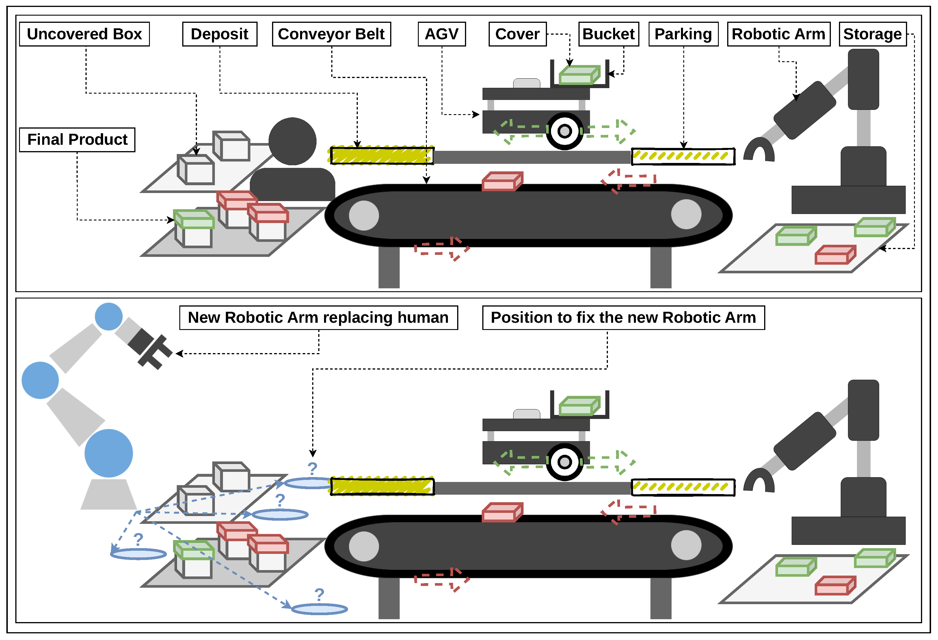
  • Module 1—Work Cell: This includes physical devices of the original PAL system as in Figure 7. Note that the new robotic arm is not yet in this PAL system.
  • Module 2—3D DTs: This includes 3D DTs running on the physical simulation generated by XDE Physics.
  • Module 3—AAS DTs: This includes AAS DTs running on an AAS server generated by P4M.
  • Module 4—Networking: This includes network hardware and software that guarantee the communication between Module 1, Module 2, and Module 3. Tag 4a in Figure 8 means that Module 1, Module 2, and Module 3 can connect and disconnect. For example, Module 1 can connect with Module 2, and they are disconnected when necessary. Tag 4b clarifies that the technologies behind Module 4 are OPC UA and TSN, and the infrastructures after them are an OPC UA server and TSN devices configured by NEON. In detail:
    OPC UA is a multipart standard for deploying industrial systems [31]. It has two contributions to the architecture. The first contribution is the OPC UA address space running on the OPC UA server that represents resources of the PAL system. Second, OPC UA network protocols in two messaging patterns, PubSub (Publish/Subscribe) and ReqRes (Request/Response), enable the physical devices and DTs to connect to the AAS werver directly and communicate between them indirectly. In detail, AAS and 3D DTs communicate with the OPC UA server based on OPC UA ReqRes, and the physical devices in the work cell communicate with the OPC UA server relying on OPC UA PubSub. Note that the robots in the work cell are not natively compatible with OPC UA but use a solution that bridges ROS 1, ROS 2, and OPC UA PubSub [32].
    TSN is a set of IEEE 802 standards that target low-latency and deterministic communications, especially for industrial systems [33]. In the architecture, TSN devices redistribute the bandwidth for communications between Module 1, Module 2, and Module 3. In other words, they can block/unblock or increase/decrease the bandwidth of any communication.
  • Module 5—Application: This includes software programs that monitor the system. They may run on different computers. First, a BPMN orchestrator developed upon the Node-RED framework (https://nodered.org/, accessed on 1 March 2023) monitors and controls AAS DTs on the AAS server. Second, UaExpert (https://unified-automation.com/products/development-tools/uaexpert.html, accessed on 1 March 2023) works as an OPC UA client that browses the OPC UA address space of the OPC UA server to observe variables and their related information associated with the PAL system’s resources. Third, as NEON fully supports the centralized model of the TSN standard IEEE 802.1Qcc, its tool, centralized user configuration (CUC), can monitor and dynamically configure the data flows exchanged between modules.
Note that Module 2 and Module 3 are the two main parts of the feasibility-checking framework, appearing only after the engineering presented in Section 5.2. Another note is that the new robotic arm has one AAS DT in Module 2 and one 3D DT in Module 3, but no physical one is in the work cell.
The architecture’s design implies some advantages that are helpful for feasibility-checking framework engineering, which are as follows.
  • AAS DTs in Module 3 can connect to their corresponding physical devices in Module 1 for AAS DT validation, independently from Module 2. This feature can help AAS DT experts to test their AAS DTs without the appearance of 3D DT experts.
  • 3D DTs in Module 2 can connect to their corresponding physical devices in Module 1 for 3D DT validation, independently from Module 3. This feature can help 3D DT experts test their 3D DTs without the appearance of AAS DT experts.
  • AAS DTs in Module 3 can connect to their corresponding 3D DTs in Module 2 for group validation, independently from Module 1. This feature enables the remote testing of AAS and 3D DTs: the DT experts do not need to be available at the testbed.
  • Module 1, Module 2, and Module 3 can collaborate simultaneously. It is practical for feasibility-checking framework validation.

5.2. Engineering the Feasibility-Checking Framework of the PAL Case Study

The feasibility-checking framework was developed in two months at CEA List. The development team includes six members from three laboratories, LSEA, LSI, and LSC, working in four domains: robotics, AAS DT, 3D DT, and networking. The engineering respects the principles of the methodology presented in Section 4.
In the specification step, a list of manufacturing entities was defined based on the state of the original PAL system. The major resources in this list include a Niryo Ned robotic arm (NNED) at the storage workstation, a conveyor belt between the two workstations (CBELT), and a TurtleBot3 Waffle Pi AGV (T3WP). Other resources, such as the storage plate at the storage workstation, the collector plate at the assembly workstation, and the table carrying the mentioned resources, are minor. Another major resource from the expected PAL system is the robotic arm UR3e. Thus, there are seven resources in total. Intermediate products transferred in this PAL system are plastic box covers. The color of a plastic box cover can be red, green, or blue. The manufacturing process is divided into three smaller processes: PaP at the storage workstation, transportation, and PaP at the assembly workstation. Among the mentioned manufacturing entities, each resource should have a 3D DT and an AAS DT, and each intermediate product should not have a 3D DT, but the total number of intermediate products should be represented by one AAS DT. The processes should be represented as submodels in AAS DTs. Also, in this step, the following inputs were prepared.
  • Datasheets of the four major resources were easily downloaded from the vendors’ websites. However, since no datasheets of the three minor resources were available, one member of the development team manually measured them and noted the measurements in a document. For example, the member measured the table’s length, width, and height with a ruler and then noted them down.
  • The historical dataset related to the original PAL system was retrieved from a database of the work cell’s OPC UA server. The dataset includes many data instances generated by the NNED, T3WP, and CBELT while operating the manufacturing process. In detail, the data of NNED are its six joints’ actual position and speed values, the data of T3WP are its two wheels’ actual position and speed values, and the data of CBELT are its speed values.
  • The AAS DT prototypes of robotic arms and AGVs in UML format were downloaded privately from an LSEA’s local server. Concerning the 3D DTs, the CAD prototypes in STEP (Standard for the Exchange of Product Data) or STL (Standard Triangle Language) format of NNED, T3WP, and UR3e were downloaded from the vendors’ websites. Their URDF files could also be found on the Internet.
  • The specification document, including the functional and non-functional requirements, was produced after the kickoff meeting. The document indicates that the privilege of the project is the functional objective. The non-functional factors, such as performance or productivity, are optional.
Then, all inputs were stored on the cloud and shared with the development team.
AAS DT experts in the development team engineered six AAS DTs. Five are for five resources: NNED, T3WP, CBELT, UR3e, and the storage plate. The final DT is an AAS DT representing the manufacturing process of the PAL system. In this case study, this manufacturing process is called a PAL process. Each AAS DT passed through three steps: design, DT implementation, and DT validation. This section only details the AAS T3WP and the AAS PAL Process since they are typical cases.
  • In the design steps, AAS DT models were designed in the P4M modeling environment using the modeling languages supported by this toolset. P4M especially proposes a new graphic modeling diagram called the AAS design diagram (ADD or add), which is compatible with the AAS specification version 3.0RC01 [34]. Figure 9 is a screenshot of the P4M modeling environment that allows users to input the information to fulfill an AAS model design. It is worth mentioning that the design content relies on the AAS DT experts’ experiences and the study at the specification step. In this case study, ADD and BPMN were used as follows.
    Figure 10 illustrates the AAS T3WP modeled in ADD. This AAS DT has five submodels: Nameplate and TechnicalProperties describe the basic information of the AGV; Bucket has the property Loaded which indicates if the bucket on top of T3WP is carrying a box cover or not; Capabilities includes the only capability of T3WP, which is Transporting; Skills lists the operations that T3WP can operate (moving forward to the deposit position, moving backward to the storage position, and turning on/off), and two properties Mission and OperationStatus indicate the robot’s current operation and the status of the last operation. The capability Transporting links to the BPMN process diagram Transporting as in Figure 11. This BPMN diagram includes a chain of service tasks representing the subprocesses needed to fulfill the capability Transporting. Each subprocess occurs when calling its associated skill. For example, the BPMN service task CALL moveToDeposit represents the process that the T3WP moves to the deposit, which happens when calling the operation moveToDeposit of AAS T3WP.
    Figure 12 illustrates the AAS PAL Process modeled in ADD. This AAS DT has three submodels: Configuration holds context information to set up the manufacturing process, which is the position of UR3e in this case; Counter contains a property that counts the number of delivered products; Service contains the BoxManufacturing service, which links to the BPMN process diagram Box Manufacturing as in Figure 13. This BPMN diagram includes a chain of three service tasks representing three capabilities required by the service BoxManufacturing. The required capability Transporting of AAS PAL Process matches with the offered capability Transporting of AAS T3WP, which means that the T3WP can work for this service.
  • In the DT Implementation steps, AAS DT experts used the P4M’s generation code feature to generate Java codes automatically from the ADD models from the design step. It is easy to trigger this feature in the P4M modeling environment with only a few clicks. Then, the experts further specified the codes with network configurations, such as the port used to listen to external applications, and compiled them to produce AAS DT running instances. The running AAS T3WP listened at port 2023 for HTTP REST requests from external applications. It communicated with the physical T3WP through the OPC UA server using OPC UA communication protocols. The running AAS PAL Process listened at port 2020 also for HTTP REST requests from external applications. The external application in this case study is the BPMN orchestrator. It was developed manually based on the BPMN diagrams in the design steps.
  • In the DT validation steps, networking experts temporarily disconnected Module 2, so the AAS DTs in Module 3 connected only with the physical devices in Module 1. AAS DT experts tested each property and operation of the AAS T3WP to verify if the response from the work cell is the same as the one in the AAS DT. For example, when calling the operation moveToDeposit, the physical T3WP must move to the deposit place; when the NNED drops a box cover into the bucket of T3WP, the property Loaded of AAS T3WP has a true value. The AAS PAL Process and other AAS DTs were tested with the same method.
Applying the above steps for every AAS DT, the output is the six AAS DTs running on the AAS server.
The 3D DT experts engineered seven 3D DTs corresponding to the seven resources: NNED, T3WP, CBELT, UR3e, the storage plate, the collector plate, and the table. Also, they created some box cover prototypes with different shapes (circle and square) and colors (red, green, and blue). Note that the DTs for box covers can be used as templates and duplicated in the physical simulation: in our demonstrator, multiple box cover instances were added. Each 3D DT passed through three steps: design, DT implementation, and DT validation. This section only details the AAS T3WP since it is a typical case.
  • In the design step, the CAD model and URDF file of T3WP are imported into XDE Physics via Unity3D. Figure 14 illustrates T3WP’s CAD model proposed by Robotis. This model has then been completed by adding a bucket onto the T3WP.
  • In the DT implementation step, additional high-level methods are added to allow for simulating the motion and behaviors of the 3D T3WP. The 3D T3WP is then integrated into the physical simulation of the complete scene. Figure 15 is a screenshot of the physical simulation.
  • In the DT validation step, the behavior of the 3D T3WP was first tested with historical data: the 3D T3WP consumed historical data corresponding to the desired position of the robot and moved adequately in the physical simulation. Second, it was validated with the real devices. Networking experts temporarily disconnected Module 3, so the 3D DTs in Module 2 are only connected with the physical devices in Module 1 in order to validate that the motion of the the real T3WP is mimicked in real time by the 3D T3WP in the physical simulation. The development members validated the 3D DT manually by eyes.
Applying the above steps for every 3D DT, the output is the seven 3D DTs running on the physical simulation generated by XDE Physics.
Next is the step taken to aggregate a manufacturing entity’s AAS DT and 3D DT into a group. There are five groups corresponding to NNED, T3WP, CBELT, UR3e, and the storage plate. The PAL process, the table, and the collector plate have either AAS DT or 3D DT; thus, they require no further aggregation validation.
In the group validation steps, networking experts temporarily disconnected Module 1, so the AAS DTs in Module 3 connected only with the 3D DTs in Module 2. Then, AAS DT experts worked together with 3D DT experts. They tested each property and operation of an AAS DT to verify if the response from the 3D DT in the same group was as expected. For example, in the group of T3WP, when calling the operation moveToDeposit from AAS T3WP, the 3D T3WP must move to the deposit place in the physical simulation; when a box cover drops into the bucket of 3D T3WP, the property Loaded of AAS T3WP has a true value.
In the feasibility-checking framework implementation step, the development team combined physical devices, AAS DTs, and 3D DTs into a united system. Most of the works are about configuring all the elements. The tools in Module 5 enable monitoring data flows passing Module 4 to detect problems while deploying the framework.
In the feasibility-checking framework validation step, Module 1, Module 2, and Module 3 were connected and run together. The BPMN orchestrator launched a manufacturing process so the development team could observe whether the physical devices in Module 1, the 3D DTs in Module 2, and the AAS DTs in Module 3 responded as expected. This test was repeated many times. The feasibility-checking framework was validated when the PAL system in the physical simulation worked nearly simultaneously with the PAL system in the work cell when operating the same manufacturing process.

5.3. Feasibility-Checking Practices and Results

Our development team installed the feasibility-checking framework on a display stand in the CEA List Tech Days 2023 on the 7th and 8th of June 2023. Figure 16 is a photo of the stand. Visitors could play as factory operators to set up the position of the 3D UR3e before runtime and turn on/off every 3D DT during runtime. Then, they could monitor the PAL system to detect errors.
To facilitate the practices of factory operators, the BPMN orchestrator had a user-friendly graphic user interface (GUI) with six predefined positions for 3D UR3e and buttons to turn on/off 3D NNED, 3D T3WP, and 3D CBELT. An example of a predefined position of 3D UR3e in the physical simulation is near the 3D DT of the collector plate; another example is a position near the 3D DT of the storage plate. It is worth noting that besides the six predefined positions, factory operators can choose every position to place the 3D UR3e in the physical simulation in real practice. Figure 17 is the screenshot of the GUI. Also, the PAL process can be reinitialized and started with only a few clicks.
With the six predefined positions of 3D UR3e, factory operators found that the PAL process worked as expected with only two positions. This result was verified manually by eyes. It was also the answer to our laboratory about the position for fixing a new physical UR3e in the testbed LocalSEA.

6. Discussion

The first point to discuss is about the methodology of N-DTs. It generally addresses heterogeneous DTs so that, in theory, it is promising to be practical in many domains other than manufacturing, such as smart building or healthcare. The advantage of this methodology is that it enables a team of multiple members from different domains to collaborate to produce a unified system. Since it is a general methodology, users can combine it with other methodologies or add details for their specific use case.
The second point to discuss is the methodology used to engineer a feasibility-checking framework. It responds to the community’s need for more shared experiences in this topic. As a specific case of N-DTs, this methodology enables AAS DT experts to work with 3D DT experts effectively. One disadvantage of this methodology is that the XDE Physics tool is closed-source; however, P4M is open-source under the Eclipse license.
Another doubt related to the second methodology is its scalability. Indeed, rendering a physical simulation with many 3D components and details may require a computer powerful enough in terms of memory and computing capabilities. Thus, it is certain that running a physical simulation of one work center composed of three work cells is more expensive than rendering and testing each work cell consecutively in the physical simulation. A way to prevent the computation of the whole system on a single computer would be to partition the work cell to distribute the workload on several computers.
Fourth, the experiment of the PAL case study can prove the concept. However, the feasibility-checking practices performed by factory operators are still manual and not precise enough. One possible approach for bridging the gap is to apply AI to verify the feasibility checking. For example, an AI engine can retrieve data from AAS DTs to calculate and conclude. This approach can also estimate non-functional requirements. For example, at position A, the UR3e may work faster than when it is at position B.

7. Conclusions and Future Works

Feasibility checking is always a critical demand in deploying and reconfiguring a manufacturing system, especially facing the growth of flexible manufacturing. This paper shares a methodology for engineering a feasibility-checking framework using AAS and 3D DTs. The framework enables factory operators to exercise feasibility-checking practices to verify a configuration with DTs before applying it to their physical work cell. One advantage of having such a framework is that the feasibility check can be processed remotely. This approach is appropriate to Industry 4.0’s vision of connected factories. The above methodology is a specific case of a more general methodology used to engineer a heterogeneous DTs system, which is not limited to manufacturing but can be applied to other domains, such as smart buildings or healthcare. The PAL case study, also presented in this paper, is not only a proof-of-concept experiment but also responds to a functional question related to the testbed LocalSEA at CEA List. However, the non-functional questions about scalability, robustness, and performance remain open and unanswered. The above contributions can be helpful to factory operators and developers searching for new technologies and methods to improve their manufacturing system.
The three laboratories participating in this project plan some improvements related to this case study. First, the P4M development team plans to implement a new module generating codes from BPMN designs. This improvement can speed up the DT implementation step. Concerning the fourth statement in the discussion section, the team is studying and searching for an effective AI approach that can predict collisions based on the geometric data retrieved from AAS DTs.
Second, the XDE Physics development team works on enhancing the performances of the physics engine, as well as handling more input formats, such as GLTF (Graphics Library Transmission Format). The platform’s new version will include a Python API that facilitates integration with deep learning algorithms and other frameworks, such as Gymnasium (https://gymnasium.farama.org/, accessed on 26 January 2024).
Third, a promising research direction for the connectivity aspect of this study is to develop a more self-configured and intelligent NEON controller. In this way, the controller can reconfigure the network when the physical system changes, such as when a device is joining/leaving the system or a network stream is starting/stopping. A machine-learning-based scheduler for the TSN network is under integration into the NEON controller, allowing this controller to schedule the TSN bridges automatically in response to the change in the physical system.

Author Contributions

Conceptualization, Q.-D.N., Y.H., and S.D.; methodology, Q.-D.N., Y.H., and S.D.; software, Q.-D.N., Y.H., F.K., C.L., and M.-T.T.; validation, Q.-D.N., Y.H., F.K., C.L., and M.-T.T.; writing—original draft preparation, Q.-D.N.; writing—review and editing, Q.-D.N., Y.H., F.K., C.L., M.-T.T., and S.D.; visualization, Q.-D.N., Y.H., C.L., and S.D.; supervision, S.D.; project administration, S.D.; funding acquisition, S.D. All authors have read and agreed to the published version of the manuscript.

Funding

This research received no external funding.

Institutional Review Board Statement

Not applicable.

Informed Consent Statement

Not applicable.

Data Availability Statement

The experiment in this paper reuses other libraries: the open-source code of the BaSyx library for P4M is available at https://github.com/eclipse-basyx/basyx-java-sdk (accessed on 1 March 2023); the open-source code of the Open62541 library for OPC UA is available at https://github.com/open62541/open62541 (accessed on 1 March 2023). The BaSyx AAS HTTP REST API for connecting to an AAS server is available at https://app.swaggerhub.com/apis/BaSyx/basyx_asset_administration_shell_http_rest_api/v1 (accessed on 1 March 2023). The CAD models of the robots are available online: the CAD model of T3WP proposed by Robotis is available at https://emanual.robotis.com/docs/en/platform/turtlebot3/features/ (accessed on 8 March 2023); the CAD model of NNED proposed by Niryo is available at https://niryo.com/download-center/ (accessed on 8 March 2023); the CAD model of UR3e proposed by Universal Robots is available at https://www.universal-robots.com/download/mechanical-e-series/ur3e/robot-step-file-ur3e-e-series/ (accessed on 8 March 2023).

Conflicts of Interest

The authors declare no conflicts of interest.

References

  1. Hu, S.J. Evolving Paradigms of Manufacturing: From Mass Production to Mass Customization and Personalization. Procedia CIRP 2013, 7, 3–8. [Google Scholar] [CrossRef]
  2. Cutting-Decelle, A.; Young, R.; Michel, J.; Grangel, R.; Le Cardinal, J.; Bourey, J. ISO 15531 MANDATE: A Product-process-resource based Approach for Managing Modularity in Production Management. Concurr. Eng. 2007, 15, 217–235. [Google Scholar] [CrossRef]
  3. Pfrommer, J.; Schleipen, M.; Beyerer, J. PPRS: Production skills and their relation to product, process, and resource. In Proceedings of the 2013 IEEE 18th Conference on Emerging Technologies & Factory Automation (ETFA), Cagliari, Italy, 10–13 September 2013; pp. 1–4. [Google Scholar] [CrossRef]
  4. Koren, Y. The Global Manufacturing Revolution: Product-Process-Business Integration and Reconfigurable Systems, 1st ed.; Wiley: Hoboken, NJ, USA, 2010. [Google Scholar] [CrossRef]
  5. Höse, K.; Amaral, A.; Götze, U.; Peças, P. Manufacturing Flexibility through Industry 4.0 Technological Concepts—Impact and Assessment. Glob. J. Flex. Syst. Manag. 2023, 24, 271–289. [Google Scholar] [CrossRef]
  6. Bayha, A.; Bock, J.; Boss, B.; Diedrich, C.; Malakuti, S. Describing Capabilities of Industrie 4.0 Components; White Paper, Plattfrom Industrie 4.0; BMWi: Berlin, Germany, 2020. [Google Scholar]
  7. Diedrich, C.; Belyaev, A.; Blumenfeld, R.; Bock, J.; Grimm, S.; Hermann, J.; Klausmann, T.; Köcher, A.; Maurmaier, M.; Meixner, K.; et al. Information Model for Capabilities, Skills & Services; Discussion Paper; Plattform Industrie 4.0; BMWi: Berlin, Germany, 2022. [Google Scholar]
  8. ISO/IEC 30173:2023-11; Digital twin—Concepts and Terminology. International Organization for Standardization: Geneva, Switzerland, 2023.
  9. Industrial Digital Twin Association. Asset Administration Shell Specification—Part 1: Metamodel Schema; Specification IDTA Number: 01001-3-0; Industrial Digital Twin Association: Frankfurt am Main, Germany, 2023. [Google Scholar]
  10. ANSI/ISA-95.00.01-2010; Enterprise-Control System Integration—Part 1: Models and Terminology. American National Standards Institute: Research Triangle Park, NC, USA, 2010.
  11. Huang, Y.; Dhouib, S.; Malenfant, J. An AAS Modeling Tool for Capability-Based Engineering of Flexible Production Lines. In Proceedings of the IECON 2021—47th Annual Conference of the IEEE Industrial Electronics Society, Toronto, ON, Canada, 13–16 October 2021; pp. 1–6. [Google Scholar] [CrossRef]
  12. Drath, R.; Weber, P.; Mauser, N. An evolutionary approach for the industrial introduction of virtual commissioning. In Proceedings of the 2008 IEEE International Conference on Emerging Technologies and Factory Automation, Hamburg, Germany, 15–18 September 2008; pp. 5–8. [Google Scholar] [CrossRef]
  13. Grieves, M. Digital Twin: Manufacturing Excellence through Virtual Factory Replication; White Paper; Dassault Systèmes: Vélizy-Villacoublay, France, 2014. [Google Scholar]
  14. Damrath, F.; Strahilov, A.; Bär, T.; Vielhaber, M. Establishing Energy Efficiency as Criterion for Virtual Commissioning of Automated Assembly Systems. Procedia CIRP 2014, 23, 137–142. [Google Scholar] [CrossRef]
  15. Sub, S.; Magnus, S.; Thron, M.; Zipper, H.; Odefey, U.; Fassler, V.; Strahilov, A.; Klodowski, A.; Bar, T.; Diedrich, C. Test methodology for virtual commissioning based on behaviour simulation of production systems. In Proceedings of the 2016 IEEE 21st International Conference on Emerging Technologies and Factory Automation (ETFA), Berlin, Germany, 6–9 September 2016; pp. 1–9. [Google Scholar] [CrossRef]
  16. Bedenbender, H.; Bentkus, A.; Epple, U.; Hadlich, T.; Heidel, R.; Hiller-meier, O.; Hoffmeister, M.; Huhle, H.; Kiele-Dunsche, M.; Koziolek, H.; et al. Industrie 4.0 Plug-and-Produce for Adaptable Factories: Example Use Case Definition, Models, and Implementation; Working Paper; Plattform Industrie 4.0; BMWi: Berlin, Germany, 2017. [Google Scholar]
  17. Lechler, T.; Fischer, E.; Metzner, M.; Mayr, A.; Franke, J. Virtual Commissioning – Scientific review and exploratory use cases in advanced production systems. Procedia CIRP 2019, 81, 1125–1130. [Google Scholar] [CrossRef]
  18. Li, W.; Gu, S.; Zhang, X.; Chen, T. Pattern Matching and Active Simulation Method for Process Fault Diagnosis. Ind. Eng. Chem. Res. 2020, 59, 12525–12535. [Google Scholar] [CrossRef]
  19. Wagner, A.; Lamoth, S.; Volkmann, M.; Hermann, J.; Ruskowski, M. Interaction between FeasibilityCheck, PreconditionCheck and SkillExecution in skill-based machining. In Proceedings of the 2023 IEEE 28th International Conference on Emerging Technologies and Factory Automation (ETFA), Sinaia, Romania, 12–15 September 2023; pp. 1–8. [Google Scholar] [CrossRef]
  20. Volkmann, M.; Sidorenko, A.; Wagner, A.; Hermann, J.; Legler, T.; Ruskowski, M. Integration of a feasibility and context check into an OPC UA skill. IFAC-Pap. 2021, 54, 276–281. [Google Scholar] [CrossRef]
  21. Singh, M.; Fuenmayor, E.; Hinchy, E.; Qiao, Y.; Murray, N.; Devine, D. Digital Twin: Origin to Future. Appl. Syst. Innov. 2021, 4, 36. [Google Scholar] [CrossRef]
  22. Muller, P.A.; Gaertner, N. Modélisation Objet Avec UML; Eyrolles: Paris, France, 2004. [Google Scholar]
  23. Srivastava, A.; Bhardwaj, S.; Saraswat, S. SCRUM model for agile methodology. In Proceedings of the 2017 International Conference on Computing, Communication and Automation (ICCCA), Greater Noida, 5–6 May 2017; pp. 864–869. [Google Scholar] [CrossRef]
  24. Dhouib, S.; Huang, Y.; Smaoui, A.; Bhanja, T.; Gezer, V. Papyrus4Manufacturing: A Model-Based Systems Engineering approach to AAS Digital Twins. In Proceedings of the 2023 IEEE 28th International Conference on Emerging Technologies and Factory Automation (ETFA), Sinaia, Romania, 12–15 September 2023; pp. 1–8. [Google Scholar] [CrossRef]
  25. Lanusse, A.; Tanguy, Y.; Espinoza, H.; Mraidha, C.; Gerard, S.; Tessier, P.; Schnekenburger, R.; Dubois, H.; Terrier, F. Papyrus UML: An open source toolset for MDA. In Proceedings of the ECMDA-FA ’09: Model Driven Architecture— Foundations and Applications: 5th European Conference, ECMDA-FA 2009, Enschede, The Netherlands, 23–26 June 2009; pp. 1–4. [Google Scholar]
  26. Platform Industrie 4.0. Details of the Asset Administration Shell—Part 2:— Interoperability at Runtime—Exchanging Information via Application Programming Interfaces; Specification Version 1.0RC02; BMWi: Berlin, Germany, 2021. [Google Scholar]
  27. Merlhiot, X.; Garrec, J.L.; Saupin, G.; Andriot, C. The XDE mechanical kernel: Efficient and robust simulation of multibody dynamics with intermittent nonsmooth contacts. In Proceedings of the 2nd Joint International Conference on Multibody System Dynamics, Stuttgart, Germany, 29 May–1 June 2012; p. 84. [Google Scholar]
  28. Weistroffer, V.; Keith, F.; Bisiaux, A.; Andriot, C.; Lasnier, A. Using Physics-Based Digital Twins and Extended Reality for the Safety and Ergonomics Evaluation of Cobotic Workstations. Front. Virtual Real. 2022, 3, 781830. [Google Scholar] [CrossRef]
  29. Thomopoulos, N.T. Assembly Line Planning and Control; Springer International Publishing: Cham, Switzerland, 2014. [Google Scholar] [CrossRef]
  30. Thi, M.T.; Ben Hadj Said, S.; Boc, M. SDN-Based Management Solution for Time Synchronization in TSN Networks. In Proceedings of the 2020 25th IEEE International Conference on Emerging Technologies and Factory Automation (ETFA), Vienna, Austria, 8–11 September 2020; Volume 1, pp. 361–368. [Google Scholar] [CrossRef]
  31. Industry Standard Specification OPC 10000-1 R1.05.2; OPC Unified Architecture—Part 1: Overview and Concepts. OPC Foundation: Scottsdale, AZ, USA, 2023.
  32. Nguyen, Q.D.; Dhouib, S.; Huang, Y.; Bellot, P. An Approach to Bridge ROS 1 and ROS 2 Devices into an OPC UA-based Testbed for Industry 4.0. In Proceedings of the 2022 IEEE 1st Industrial Electronics Society Annual On-Line Conference (ONCON), kharagpur, India, 9–11 December 2022; pp. 1–6. [Google Scholar] [CrossRef]
  33. IEEE Std 802.1Q-2011/Cor 2-2012 (Corrigendum to IEEE Std 802.1Q-2011); IEEE Standard for Local and Metropolitan Area Networks–Media Access Control (MAC) Bridges and Virtual Bridged Local Area Networks–Corrigendum 2: Technical and Editorial Corrections. IEEE: Piscataway, NJ, USA, 2012; pp. 1–96. [CrossRef]
  34. Plattform Industrie 4.0. Details of the Asset Administration Shell—Part 1:— The Exchange of Information between Partners in the Value Chain of Industrie 4.0; Specification Version 3.0RC01; BMWi: Berlin, Germany, 2021. [Google Scholar]
Figure 1. Feasibility checking in the CCEO methodology proposed by Plattform Industrie 4.0.
Machines 12 00095 g001
Figure 2. Methodology of N-DTs.
Machines 12 00095 g002
Figure 3. Contributions of P4M and XDE Physics to the feasibility-checking model.
Machines 12 00095 g003
Figure 4. AAS server with an AAS DT, generated by P4M.
Machines 12 00095 g004
Figure 5. Physical simulation with a 3D DT. The model is first defined in Unity using CAD and eventually a URDF file for the physical properties. Then, during the physical simulation, the simulated robot can communicate with the real platform via ROS, WS, or OPC UA.
Machines 12 00095 g005
Figure 6. Methodology used to engineering feasibility-checking framework of AAS and 3D DTs.
Machines 12 00095 g006
Figure 7. The original PAL system (up) and the expected one (down).
Machines 12 00095 g007
Figure 8. Major components involved in the PAL case study.
Machines 12 00095 g008
Figure 9. P4M modeling environment based on the integrated development environment (IDE) Eclipse. It also includes other practical features, such as drag-and-drop designing.
Machines 12 00095 g009
Figure 10. ADD of AAS T3WP. The submodel with template kind is a prototype, and the submodel with instance kind is a concrete object with details. While the underlined properties hold static values that are unchangeable at operation time, the non-underlined ones hold dynamic values.
Machines 12 00095 g010
Figure 11. BPMN of the subprocesses related to T3WP’s Transporting.
Machines 12 00095 g011
Figure 12. ADD of AAS PAL Process.
Machines 12 00095 g012
Figure 13. BPMN of the three processes related to the PAL process.
Machines 12 00095 g013
Figure 14. CAD model of a TurtleBot3 Waffle Pi proposed by Robotis.
Machines 12 00095 g014
Figure 15. 3D T3WP and other 3D DTs in the physical simulation generated by XDE Physics.
Machines 12 00095 g015
Figure 16. The display stand of the PAL case study at CEA List Tech Days 2023.
Machines 12 00095 g016
Figure 17. Screenshot of the BPMN orchestrator’s management dashboard. Each circle led in the window Monitor can have one of the three colors: green, red, and gray. Green means ON, red means OFF, and gray means no connection between the BPMN orchestrator and the AAS server.
Machines 12 00095 g017
Table 1. Research works contributing to feasibility checking in manufacturing.
[12][13][14][15][16][17][18][19]
Engineering Stage
Production Stage
Graphical Simulation
Pattern Matching
Mathematical–Physical Calculation
Digital Twin
Table 2. Formula used to calculate the total number of DTs in an N-DTs system.
N = i = 1 h n i
where
  • N: total number of DTs.
  • h: number of DT types in an N-DTs system, e.g., h = 3 means that there are three DT types.
  • ni: number of DTs having the DT type i.
Disclaimer/Publisher’s Note: The statements, opinions and data contained in all publications are solely those of the individual author(s) and contributor(s) and not of MDPI and/or the editor(s). MDPI and/or the editor(s) disclaim responsibility for any injury to people or property resulting from any ideas, methods, instructions or products referred to in the content.

