Article

Cutting Performance and Tool Wear of AlCrN- and TiAlN-Coated Carbide Tools during Milling of Tantalum–Tungsten Alloy

1
College of Mechanical Engineering, Zhejiang University of Technology, Hangzhou 310023, China
2
Southwest Technology and Engineering Research Institute, Chongqing 400039, China
*
Author to whom correspondence should be addressed.
Machines 2024, 12(3), 170; https://doi.org/10.3390/machines12030170
Submission received: 24 January 2024 / Revised: 22 February 2024 / Accepted: 28 February 2024 / Published: 1 March 2024
(This article belongs to the Section Material Processing Technology)

Abstract

:
Tantalum–tungsten alloys have been widely used in different industrial sectors—for example, in chemical, medical, aerospace, and military equipment. However, they are usually difficult to cut because of the large cutting force, rapid tool wear, and poor surface finish during machining. This paper presents the machining performance and cutting tool wear of AlCrN/TiAlN-coated carbide tools during the milling process of Ta-2.5W. The effects of cutting parameters on the cutting forces and surface roughness of AlCrN/TiAlN-coated carbide tools were obtained and analyzed. The results show that the wear resistance of AlCrN-coated tools is better than that of TiAlN-coated tools, and that the main wear mechanisms of both cutting tools are crater wear, adhesive wear, and diffusion wear. Compared to TiAlN-coated tools, AlCrN-coated tools reduced the cutting forces by 1% to 15% and decreased the surface roughness by 6% to 20%. A cutting speed within the range of 80–120 m/min can ensure a low cutting force while maintaining good surface roughness, which is more conducive to machining Ta-2.5W.

1. Introduction

With the development of manufacturing industries, tantalum–tungsten alloys have gained popularity due to their high strength, high melting point, good ductility, corrosion resistance, wear resistance, and high-temperature mechanical properties [1]. In recent years, they have been widely used in the field of electronics, the chemical industry, aerospace, national defense, the military industry, biomedicine, etc., as a material for parts such as aviation engines, gas turbines, weapons and equipment, and human sponge bones [2,3,4,5]. However, due to their good plasticity and high strain-hardening capacity, they cause problems such as large cutting forces, elevated temperatures, and poor chip breaking [6,7]. This problem can lead to various forms of tool wear, including chipping, notch wear, and adhesive wear [8]. Tool wear can lead to reduced processing stability, reduced workpiece dimensional accuracy and surface quality, and, in turn, reduced processing efficiency and tool life [9,10]. Therefore, studying the machinability of tantalum–tungsten alloys and their tool wear mechanism, and optimizing the cutting parameters to improve cutting efficiency and tool life is of great practical significance.
To investigate the machining difficulties of tantalum and its alloys, several scholars have analyzed the deformation behavior of tantalum–tungsten alloys. Gao et al. [11] used the quasi-static, SHPB, and Taylor impact experimental results of Ta-2.5W and Ta-10W to develop and validate an empirically based constitutive relation for flow stress. Gourdin et al. [12] observed that adding tungsten solutes to tantalum significantly reduced the strain rate sensitivity of the flow stress near the yield in tantalum, and work hardening increased with the rate of addition. Khan et al. [13] proposed a new constitutive model based on a series of stress–strain experiments on tantalum and its alloys (Ta-2.5W). Subsequently, Zhou et al. [14] experimentally validated this model, demonstrating its higher correlation with the published data on tantalum–tungsten alloys compared to other models. Furthermore, their work confirmed that the work-hardening behavior of tantalum and its alloys is a combined result of strain, strain rate, and temperature hardening. Davis et al. [7] examined the plastic flow kinetics of tantalum, applying Surface Adsorption (SA) media to the initial workpiece surface, which triggered Mechano-Chemical (MC) effects in the substantial strain deformation of metals, resulting in a reduction in cutting forces of over 70% and a tenfold improvement in surface finish. As can be seen, in order to improve the processing quality of tantalum–tungsten alloys, the influence of work hardening needs to be minimized as much as possible.
The cutting parameters play a crucial role in the wear of cutting tools and the quality of machining surfaces during the machining process. Appropriate cutting parameters can significantly improve machining quality and production efficiency. The cutting parameters of tantalum–tungsten alloys have been preliminary studied. Wang et al. [15], using tungsten carbide tools in the machining of pure tantalum with parameters set to v = 21 m/min, ap = 0.08 mm, and f = 0.08 mm/r, found that, compared to traditional machining, cryogenically enhanced machining improved the surface roughness by 200% and the tool life by 300%. Mizutani et al. [16] conducted ultra-precision machining experiments on pure tantalum using tools with rake angles of 23°, 28°, and 33°, respectively. Their results indicated that a rake angle of 28° minimized the cutting forces and surface roughness while extending tool life. Wang et al. [17], targeting tool life, optimized the cutting parameters through orthogonal experiments, concluding that the optimal parameters for Ta-2.5W under water-based cooling are a cutting speed of 120 m/min, cutting depth of 0.1 mm, and feed rate of 0.125 mm/r.
Furthermore, tool wear can increase cutting forces and temperatures, adversely affecting the surface quality and efficiency of machining [18]. Due to the characteristics of tantalum–tungsten alloys, traditional tools struggle with their machining. However, the combination of the superior wear and oxidation resistance of hard coatings, applied via Physical Vapor Deposition (PVD) technology, with tool materials significantly extends tool life [19,20]. Kumar et al. [21] compared the wear behaviors of uncoated and AlCrN- and AlTiN-coated tools in high-hardness steel cutting tests. The results showed that AlTiN-coated tools exhibited better oxidation, wear, and adhesion resistance, while AlCrN coatings performed better in high-speed cutting. Lazarus [22] found, in turning tests of Ta-2.5W, that adding an AlCrN coating to a TiAlN coating increased tool life by 15% to 20%.
However, there is currently very little research on the effects of different parameters on the machining of tantalum–tungsten alloys. Moreover, although studies indicate that coated cutting tools perform well in machining Ta-2.5W, they do not provide a suitable range of cutting parameters. This study aims to investigate the impact of cutting parameters on cutting forces and surface roughness during the machining of Ta-2.5W. Additionally, it presents the cutting performance of TiAlN/AlCrN-coated carbide tools and the mechanisms of cutting tool wear.

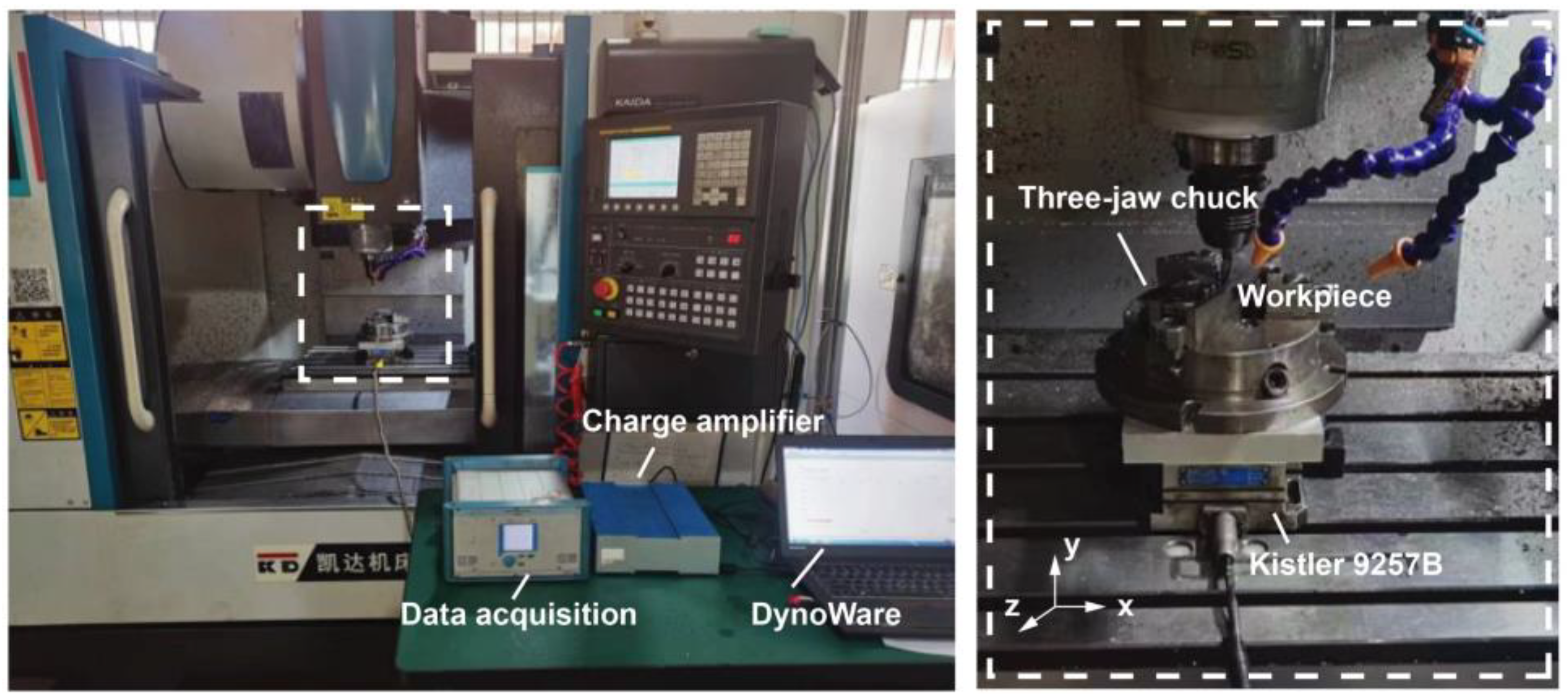
2. Materials and Methods

The workpiece used in this experiment was a Ta-2.5W round bar with dimensions of Φ65 mm × 150 mm. The main chemical composition of the Ta-2.5W is outlined in Table 1. The yield strength, measured through quasi-static compression testing, was determined to be 286 MPa, as illustrated in Figure 1. The cutting tools selected were TiAlN-coated and AlCrN-coated carbide tools, each with a diameter of 10 mm. These cutting tools had four flutes, a flute length of 25 mm, and a helix angle of 35°. Based on our summary of cutting experiments on tantalum and its alloys, a single-factor test was set up for cutting speed, and the cutting parameters are shown in Table 2.
Figure 2 illustrates the experimental setup of this study. All experiments were conducted on a KDVM800LH vertical machining center. A piezoelectric three-directional dynamometer (Kistler 9257B, Winterthur, Switzerland) collected real-time cutting force signals. The data were displayed on a laptop using DynoWare version 2.5.3.8, with the sampling rate set at 2 kHz. At the end of each set of experiments, the surface roughness of the workpiece was measured using a digital microscope (Keyence VHX-7100, Osaka, Japan). Measurements were taken at five random points for each set, and the average value was recorded. On the other hand, the cutting tool wear was analyzed using a scanning electron microscope (ZEISS Sigma 300, Berlin, Germany).

3. Results and Discussion
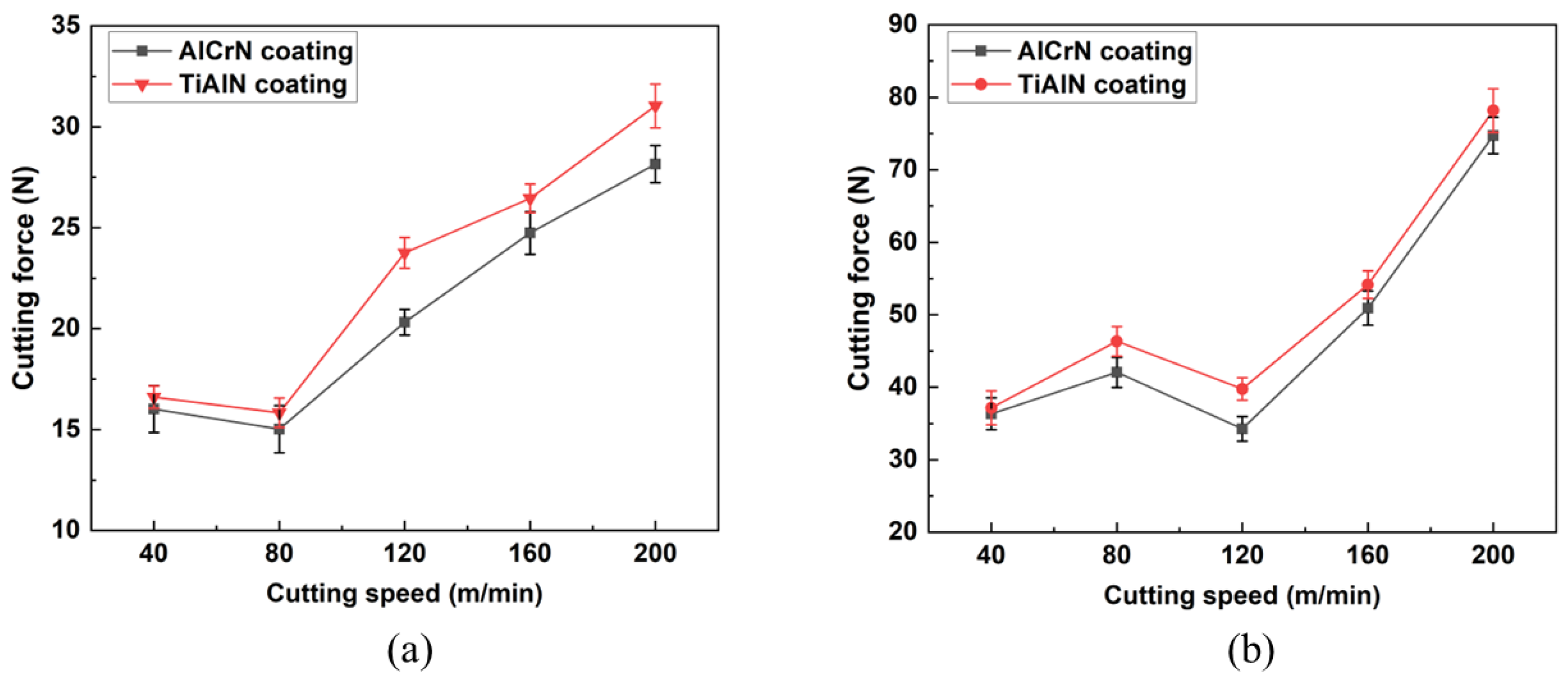
3.1. Cutting Forces

In this experiment, the maximum value of the cutting force signals in three directions (Fx, Fy, Fz) was exported using DynoWare universal data acquisition and analysis software. Excluding the peak force signals of individual extreme sudden changes, we measured the forces in three directions during the stable milling stage and utilized Formula (1) to calculate the cutting force for analysis.
F = (Fx2 + Fy2 + Fz2)1/2,
Figure 3 presents the resultant cutting forces for both AlCrN-coated and TiAlN-coated tools when machining Ta-2.5W under various cutting parameters. As Figure 3 illustrates, the cutting forces of the two coated tools are very similar, with nearly identical trends. Under the same cutting parameters, the cutting force of the AlCrN-coated tool is reduced by 1% to 15% compared to the TiAlN-coated tool. Figure 3a shows that when f = 0.1 mm/r, ap = 0.2 mm, and ae = 1 mm, the cutting forces for both coatings increase with an increase in cutting speed, with the TiAlN-coated tool being more affected by cutting speed. Figure 3b illustrates that, as f, ap, and ae increase, the cutting forces of both types of coated tools significantly rise. When the cutting speed is between 40 and 120 m/min, there is a trend of initial increase followed by a decrease in cutting force, with the smallest increase in cutting force at a speed of 120 m/min. This also corroborates the findings of researchers such as Wang [17] and Lazarus [22], who advocate for machining tantalum–tungsten alloys at 120 m/min to extend tool life. Additionally, it should be noted that the installation of a relatively heavy fixture on the dynamometer may result in damping, leading to a loss of cutting force, especially at higher cutting speeds. Therefore, there may be some error in the measured cutting force.
From the perspective of tool wear, the AlCrN and TiAlN coatings exhibit similar widths and forms of wear on the flank face. However, the wear on the rake face shows that the AlCrN-coated tool has less wear and better wear resistance, which can reduce friction between the tool and the workpiece. Therefore, the overall cutting forces of the two coatings are not significantly different, with the AlCrN-coated tool exhibiting a lower cutting force. Moreover, due to the strain hardening characteristic of Ta-2.5W, the cutting force significantly increases after the cutting speed reaches a certain level due to the work hardening of the material. The cutting speed significantly impacts the cutting force when machining tantalum–tungsten alloys. Additionally, other cutting parameters also play an important role. Therefore, to reduce the cutting force during the machining of tantalum–tungsten alloys, lower cutting speeds should be employed, and other cutting parameters should also be moderated.

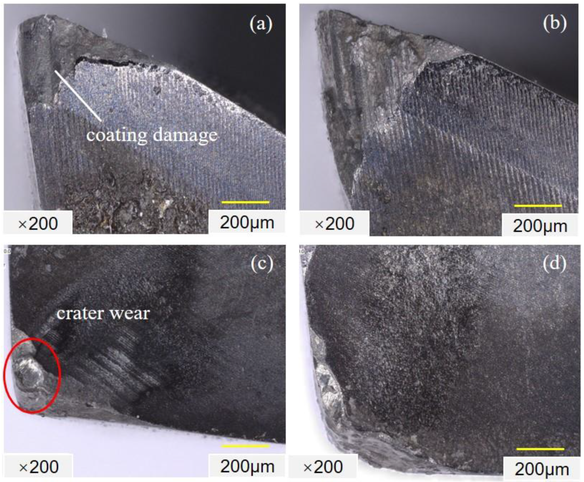
3.2. The Condition of the Tool’s Surface Wear

Figure 4 and Figure 5 show the surface wear of AlCrN- and TiAlN-coated carbide tools, respectively, under the parameters of v = 120 m/min, f = 0.2 mm/r, ap = 0.4 mm, and ae = 2 mm, during the dry milling of Ta-2.5W. Figure 4a and Figure 5a show that this is the area where the maximum wear occurs on the tool face. As the surface of the workpiece is susceptible to work hardening during milling, it becomes the area where the machined material is located. Consequently, the flank face is more prone to wear than other parts of the cutting edge, resulting in the formation of a V-shaped notch. This V-shaped notch is a typical characteristic of groove wear, which severely affects tool life [9]. Figure 5c reveals that the AlCrN-coated tool shows relatively minor wear on the rake face after 10 min of machining, but chipping occurs at the tool tip. This is attributed to the formation of a built-up edge (BUE) due to the high plasticity of the material and the high temperature and pressure in the cutting zone. The BUE, acting as a substitute for the tool edge in cutting, somewhat reduces tool wear. However, due to the continuous shedding and formation of these BUEs, the surface quality and dimensional accuracy of the machined surface will be affected. Additionally, BUE contributes to the blunting of the cutting edge. This dulling effect escalates the force required for cutting and the temperature during the process. It also impedes the efficient removal of chips, subsequently influencing the durability and performance of the cutting tool. Figure 4d indicates severe wear at the tool tip after 20 min of machining, accompanied by surface collapse and pitting. This is because a milling cutter with a complete cutting edge experiences the highest stress at the edge, while a milling cutter with a notched edge has its maximum stress near the notch, leading to stress concentration and accelerated tool wear. In Figure 5c, the TiAlN-coated tool shows significant rake face wear after 10 min of machining, with crescent-shaped wear at the tip and a surrounding collapse. After 20 min of machining, Figure 5d shows that the wear of the TiAlN-coated tool has greatly increased, with the cutting edge nearly disappearing, indicating tool failure.

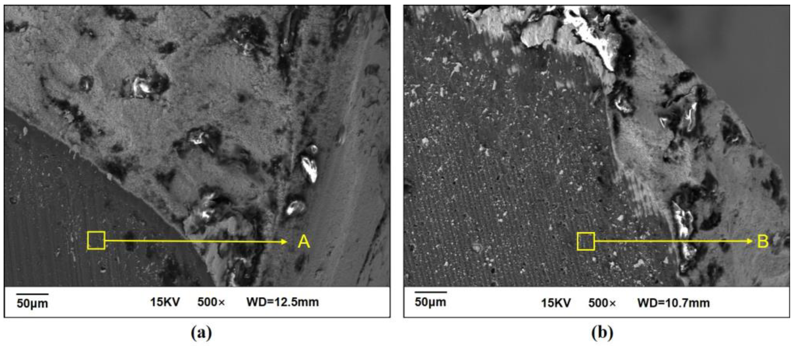
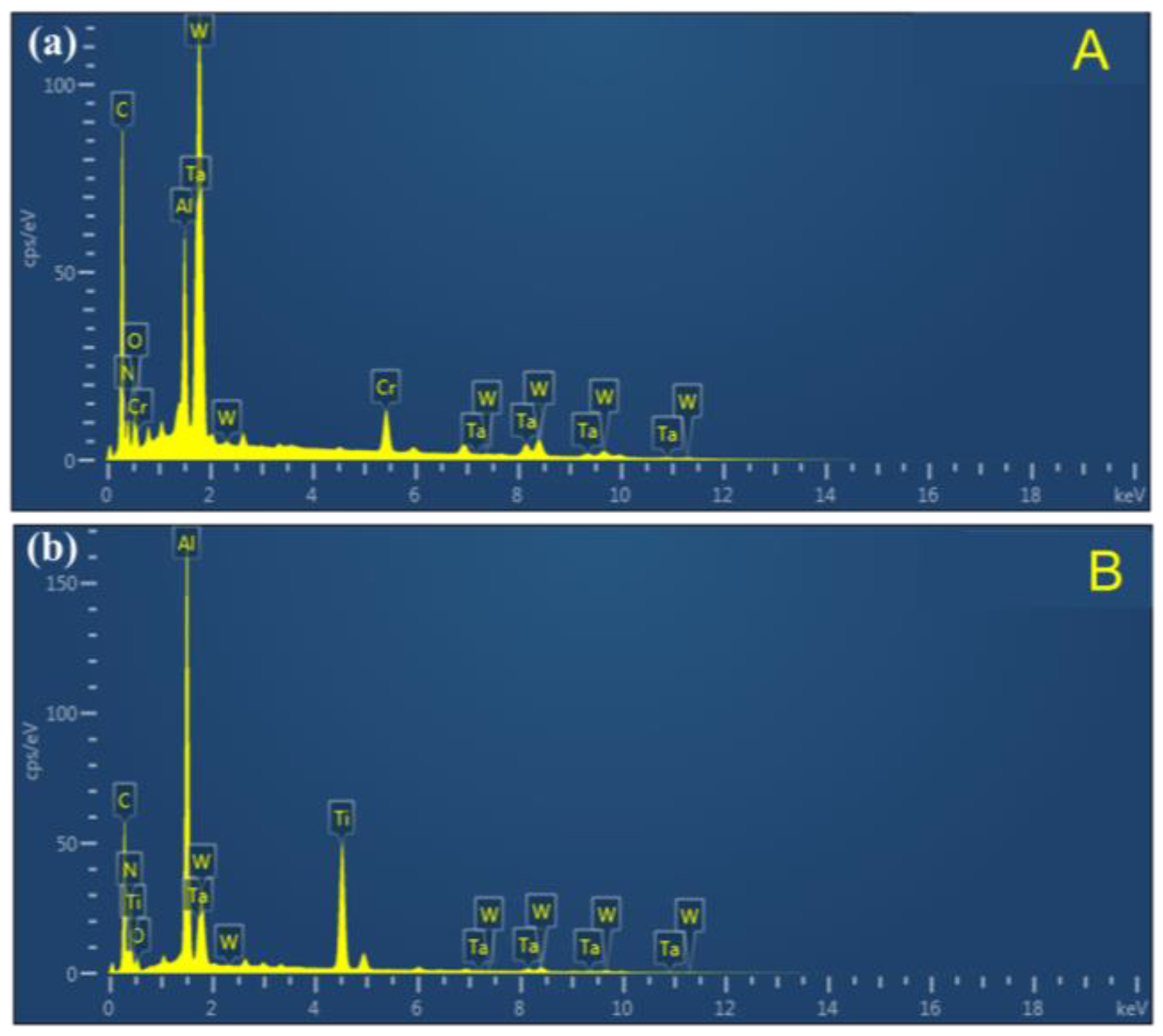
3.3. Tool Wear Behavior and Its Related Mechanism

Figure 6 presents the scanning electron microscope (SEM) micrographs of the rake faces of AlCrN- and TiAlN-coated tools after 20 min of machining under the conditions v = 120 m/min, f = 0.2 mm/r, ap = 0.4 mm, and ae = 2 mm. Due to the good plasticity of the tantalum–tungsten alloy, a built-up edge was prevalent during the machining experiments, which has also been observed in previous studies [8]. On the other hand, the surfaces of the coated tools have partially delaminated coatings, and there is a significant amount of adhered material in the wear area due to the generation of chips and chip fragments during milling. As a result, the friction between the cutting tool and the material generates significant heat, leading to elevated pressure and temperatures. This environment causes cutting chips and fragments to adhere to the workpiece surface. Due to the continuous relative movement between the workpiece and the tool, the adhesion point will break, and a little part of the tool material will be removed, causing adhesive wear.
Figure 7 shows the Energy Dispersive Spectroscopy (EDS) analysis of areas A and B, and the elemental compositions of AlCrN/TiAlN-coated carbide tools are shown in Table 3 and Table 4, respectively. Figure 7a and Table 3 show that, in area A, the mass percentages of Ta and W are 14.18% and 28.90%, respectively, which are much higher than those of Al (4.71%) and Cr (6.24%). This suggests that elements from the workpiece material have diffused into the tool. In contrast, Figure 7b and Table 4 show that, in area B, the proportions of Ta and W are relatively lower, at 5.25% and 8.60%, respectively, while those of Al and Ti are 16.81% and 20.60%, respectively. This indicates some degree of elemental diffusion in the TiAlN-coated tool, though not as severe as in the AlCrN-coated tool. The O content in area B of the TiAlN-coated tool was lower than that of the AlCrN-coated tool, implying lower oxidation wear, which can effectively improve tool service life [23]. However, the low percentages of O in areas A and B indicate that the oxidation reaction occurring in this region is not severe. In conclusion, under the same parameter conditions, the AlCrN coating exhibits better wear resistance than the TiAlN coating; furthermore, the primary forms of wear during the milling of Ta-2.5W with AlCrN- and TiAlN-coated tools are adhesive and diffusion wear.

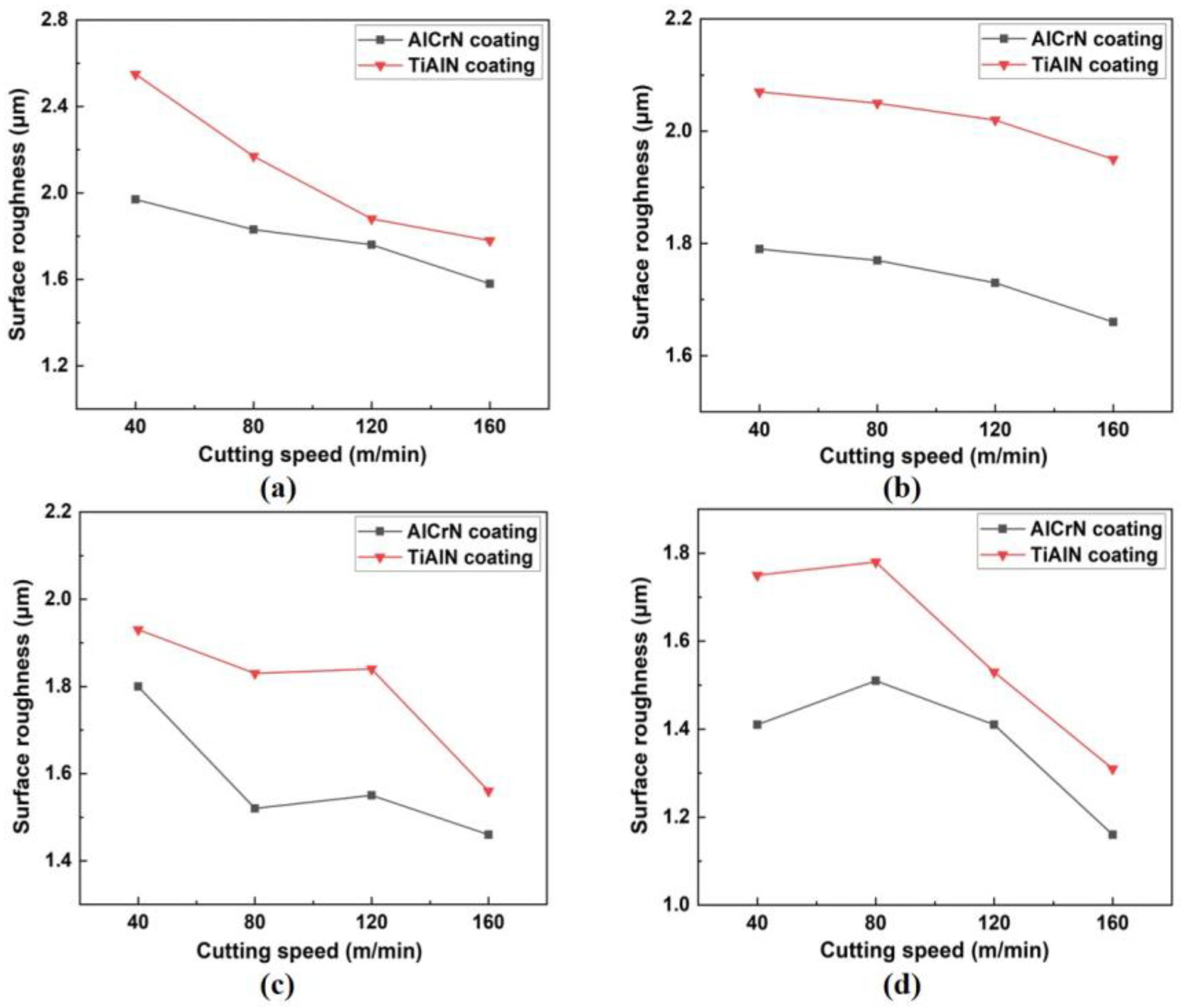
3.4. Surface Roughness

Figure 8 shows the machined surface roughness under different cutting parameters. It is observed that the surface roughness for both coated tools decreases with an increase in the cutting speed. This decrease is attributed to the high plasticity of the tantalum–tungsten alloy Ta-2.5W. At lower cutting speeds, chips adhere to the milling cutter’s teeth, forming large and unstable BUEs. BUEs alter the tool’s cutting angle, diminishing its milling performance and producing a poorer surface quality. As the cutting speed and feed rate increase, work hardening of the material occurs, resulting in increased strength and reduced plasticity, thereby gradually diminishing the BUEs and consequently lowering the surface roughness. By comparing the changes in surface roughness under four different cutting parameters, as seen in Figure 8, starting with initial conditions of ap = 0.2 mm, ae = 1 mm, and f = 0.1 mm/r, increases in cutting depth, cutting width, or feed rate each lead to varying degrees of surface roughness reduction. As seen in Figure 8b, when the cutting width is increased to 2 mm, the reduction in surface roughness is minimal, and this parameter exhibits the greatest stability in the 40~120 m/min speed range, roughness reduction within 0.2 μm. In Figure 8d, increasing the feed rate from 0.1 mm/r to 0.2 mm/r results in a 0.5 μm decrease in surface roughness, which reaches below 1.6 μm, indicating an optimal surface finish. Comparatively, the superior hardness and exceptional wear resistance of AlCrN coatings contribute to enhanced cutting edge stability, mitigating wear and thus preserving a sharper and more precise cutting edge throughout the machining process. This leads to smoother surfaces; under the same conditions, the surface roughness from AlCrN-coated tools decreases by 6% to 20% more than that for TiAlN-coated tools.

4. Conclusions

In this paper, the cutting performance and wear mechanism of TiAlN/AlCrN-coated tools during the machining of tantalum–tungsten alloys are studied. The machining process was studied in terms of two aspects: cutting force and surface roughness. According to the analyses provided, the following results were obtained:
(1).
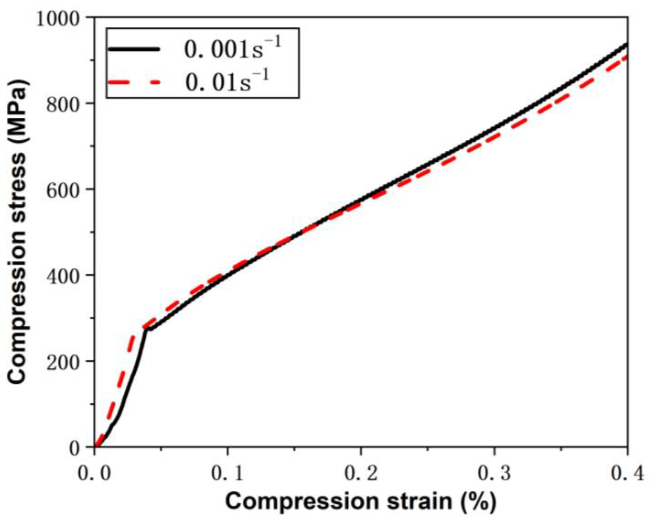
During the milling of tantalum–tungsten alloy Ta-2.5W at a low cutting speed, the high plasticity of the material frequently leads to the adherence of chips to the cutting tool, forming a BUE and deteriorating the surface roughness. As the cutting speed increases, the work-hardening effect intensifies, resulting in enhanced material strength and reduced plasticity, which in turn causes a rapid increase in the cutting forces and an improvement in surface roughness.
(2).
When machining tantalum–tungsten alloy Ta-2.5W, the superior hardness and exceptional wear resistance of AlCrN coatings stabilize the cutting edge more effectively than TiAlN-coated tools; this results in a reduction in cutting forces by 1% to 15% and a decrease in surface roughness by 6% to 20%.
(3).
Under dry milling conditions of Ta-2.5W at a cutting speed of 120 m/min, feed rate of 0.2 mm/r, cutting depth of 0.4 mm, and cutting width of 2 mm, the primary wear observed on both coatings was concentrated on the flank face, with similar wear magnitudes observed. However, at the rake face, AlCrN coatings demonstrated superior wear resistance. Furthermore, the main wear mechanisms of AlCrN-coated and TiAlN-coated tools were crater wear, adhesive wear, and diffusion wear.
Subsequent studies could further investigate the relationship between cutting parameters and tool life to better enhance the quality and efficiency of machining tantalum–tungsten alloys.

Author Contributions

Conceptualization, J.W.; methodology, J.W.; formal analysis, J.W. and Z.L.; investigation, J.W.; resources, D.S.; data curation, Z.L.; writing—original draft preparation, J.W. and Z.L.; writing—review and editing, Y.W. and Q.W.; visualization, Y.W. and Q.W.; supervision, Z.L., Y.W., Q.W. and D.S.; project administration, Z.L., Q.W. and D.S.; funding acquisition, Q.W. All authors have read and agreed to the published version of the manuscript.

Funding

This research received no external funding.

Data Availability Statement

Data will be made available upon request.

Conflicts of Interest

The authors declare that they have no known competing financial interests or personal relationships that could have appeared to influence the work reported in this paper.

References

  1. Ma, G.; Wei, Z.; Wu, G.; Mao, X. The microstructure and strength of a tantalum alloy: Influence of temperature. Mater. Sci. Eng. A 2023, 880, 145312. [Google Scholar] [CrossRef]
  2. Agrawal, M.; Jha, R.; Singh, K.K.; Singh, R. Optimization of Leaching Parameters for Recovery of Tantalum from Waste Tantalum Capacitors. In Springer Proceedings in Physics: Proceedings of the 3rd International Conference on Advances in Materials Processing: Challenges and Opportunities, Roorkee, India, 17–19 October 2023; Springer Nature Singapore: Singapore, 2023; Volume 293, pp. 213–218. [Google Scholar] [CrossRef]
  3. Stelmakh, V.; Rinnerbauer, V.; Chan, W.R.; Senkevich, J.J.; Joannopoulos, J.D.; Soljacic, M.; Celanovic, I. Tantalum-tungsten alloy photonic crystals for high-temperature energy conversion systems. Conf. Photonic Cryst. Mater. Devices 2014, 9127, 116–124. [Google Scholar] [CrossRef]
  4. Liu, G.; Gu, X.; Heng, F.; Men, J. Microstructure evolution and deformation mechanism with comparison of Ta-2.5 W and Cu under detonation load. Mater. Today Commun. 2024, 38, 107737. [Google Scholar] [CrossRef]
  5. Cheng, C.; Fu, Y.; Du, C.; Du, Z.; Jiang, Z.; Zhou, F.; Zhong, K.; Wang, X. Experimental and numerical study of tantalum-tungsten alloy rod penetrator impacting thick armor plate. Int. J. Refract. Met. Hard Mater. 2022, 107, 105873. [Google Scholar] [CrossRef]
  6. Chen, S.R.; Gray, G.T. Constitutive behavior of tantalum and tantalum-tungsten alloys. Metall. Mater. Trans. A-Phys. Metall. Mater. Sci. 1996, 27, 2994–3006. [Google Scholar] [CrossRef]
  7. Davis, J.M.; Saei, M.; Mohanty, D.P.; Udupa, A.; Sugihara, T.; Chandrasekar, S. Cutting of tantalum: Why it is so difficult and what can be done about it. Int. J. Mach. Tools Manuf. 2020, 157, 103607. [Google Scholar] [CrossRef]
  8. Burgess, J.W. Wear of Nanostructured Tool Coatings Bonded to Turning Inserts Dry Turning a Tantalum Tungsten Alloy; Purdue University: West Lafayette, IN, USA, 2009; p. 145. [Google Scholar]
  9. Li, W.J.; Zhou, B.W.; Xing, L.J.; He, H.; Ni, X.J.; Li, M.J.; Gong, Z.H. Influence of cutting parameters and tool nose radius on the wear behavior of coated carbide tool when turning austenitic stainless steel. Mater. Today Commun. 2023, 37, 107349. [Google Scholar] [CrossRef]
  10. Abukhshim, N.A.; Mativenga, P.T.; Sheikh, M.A. Heat generation and temperature prediction in metal cutting: A review and implications for high speed machining. Int. J. Mach. Tools Manuf. 2006, 46, 782–800. [Google Scholar] [CrossRef]
  11. Fei, G.; Zhang, X.; Ahmad, S.; Wang, M.Y.; Li, L.; Xiong, W.; Zhang, J. Dynamic Behavior and Constitutive Model for Two Tantalum-Tungsten Alloys under Elevated Strain Rates. Rare Met. Mater. Eng. 2017, 46, 2753–2762. [Google Scholar] [CrossRef]
  12. Gourdin, W.H.; Lassila, D.H.; Leblanc, M.M.; Shields, A.L. The influence of tungsten alloying on the mechanical-properties of tantalum. J. De Phys. LV 1994, 4, 207–212. [Google Scholar] [CrossRef]
  13. Khan, A.S.; Liang, R. Behaviors of Three BCC Metal Over a Wide Range of Strain Ratesand Temperatures Experiments and Modeling. Int. J. Plast. 1999, 15, 1089–1109. [Google Scholar] [CrossRef]
  14. Zhou, J.; Khan, A.S.; Cai, R.; Chen, L. Comparative study on constitutive modeling of tantalum and tantalum tungsten alloy. J. Iron Steel Res. Int. 2006, 13, 68–74. [Google Scholar] [CrossRef]
  15. Wang, Z.; Rajurkar, K.P.; Fan, J.; Petrescu, G. Cryogenic machining of tantalum. J. Manuf. Process. 2002, 4, 122–127. [Google Scholar] [CrossRef]
  16. Mizutani, M.; Naruse, T.; Kameyama, Y.; Koma, Y.; Ohmori, H.; Sasaki, C. Fabrication of cutting tools for ultraprecision machining of tantalum and their cutting characteristics. J. Vac. Sci. Technol. B 2009, 27, 1367–1369. [Google Scholar] [CrossRef]
  17. Wang, R.; Wang, X.; Yan, P.; Zhou, T.; Jiao, L.; Teng, L.; Zhao, B. The effects of cryogenic cooling on tool wear and chip morphology in turning of tantalum-tungsten alloys Ta-2.5W. J. Manuf. Process. 2023, 86, 152–162. [Google Scholar] [CrossRef]
  18. Umut, K.; Erhan, B. Investigating effects of milling conditions on cutting temperatures through analytical and experimental methods. J. Mater. Process. Technol. 2017, 262, 532–580. [Google Scholar] [CrossRef]
  19. He, H.B.; Li, H.Y.; Zhang, X.Y.; Yue, Q.B.; Zhang, J.; Ma, L.; Li, Y.M. Research on the Cutting Performances and Wear Mechanisms of TiAlCrN Coated Tools During Dry Turning. Int. J. Precis. Eng. Manuf. 2019, 20, 201–207. [Google Scholar] [CrossRef]
  20. Das, S.; Dhupal, D.; Kumar, A. Experimental investigation into machinability of hardened AISI 4140 steel using TiN coated ceramic tool. Measurement 2015, 62, 108–126. [Google Scholar] [CrossRef]
  21. Kumar, C.S.; Patel, S.K. Effect of chip sliding velocity and temperature on the wear behaviour of PVD AlCrN and AlTiN coated mixed alumina cutting tools during turning of hardened steel. Surf. Coat. Technol. 2018, 334, 509–525. [Google Scholar] [CrossRef]
  22. Lazarus, L.J. Topical report: Tantalum-2.5% tungsten machinability testing. Honeywell Fed. Manuf. Technol. 2009, 12–13. [Google Scholar] [CrossRef]
  23. Iram, S.; Cai, F.; Wang, J.; Zhang, J.; Liang, J.; Ahmad, F.; Zhang, S. Effect of Addition of Mo or V on the Structure and Cutting Performance of AlCrN-Based Coatings. Coatings 2020, 10, 298. [Google Scholar] [CrossRef]
Figure 1. Ta-2.5W quasi-static test.
Machines 12 00170 g001
Figure 2. CNC milling machine and experimental setup of this study.
Machines 12 00170 g002
Figure 3. Cutting force under different cutting parameters for AlCrN/TiAlN-coated carbide tools: (a) f = 0.1 mm/r, ap = 0.2 mm, ae = 1 mm; (b) f = 0.2 mm/r, ap = 0.4 mm, ae = 2 mm.
Machines 12 00170 g003
Figure 4. Tool wear of AlCrN-coated carbide tools: (a) 10 min flank wear; (b) 20 min flank wear; (c) 10 min rake wear; (d) 20 min rake wear.
Machines 12 00170 g004
Figure 5. Tool wear of TiAlN-coated carbide tools: (a) 10 min flank wear; (b) 20 min flank wear; (c) 10 min rake wear; (d) 20 min rake wear.
Machines 12 00170 g005
Figure 6. SEM results of the rake faces for (a) an AlCrN-coated carbide tool and (b) a TiAlN-coated carbide tool.
Machines 12 00170 g006
Figure 7. EDS results of wear regions for (a) region A and (b) region B, corresponding to the boxes in Figure 6.
Machines 12 00170 g007
Figure 8. Surface roughness under different cutting parameters and coating materials: (a) ap = 0.2 mm, ae = 1 mm, and f = 0.1 mm/r; (b) ap = 0.2 mm, ae = 2 mm, and f = 0.1 mm/r; (c) ap = 0.4 mm, ae = 1 mm, and f = 0.1 mm/r; (d) ap = 0.2 mm, ae = 1 mm, and f = 0.2 mm/r.
Machines 12 00170 g008
Table 1. Main chemical composition of Ta-2.5W.
ElementsWCNHOFeTiNbTa
Wt (%)2.750.010.010.00150.0150.010.010.5BAL
Table 2. Cutting parameters of tests.
FactorsLevel 1Level 2Level 3Level 4Level 5
Cutting speed (m/min)4080120160200
Feed per tooth (mm/r)0.10.2
Axial depth of cut (mm)0.20.4
Radial depth of cut (mm)12
Table 3. Elemental composition of AlCrN-coated tool.
ElementWeight Percentage (%)
C34.73
O4.14
Al4.71
Cr 6.24
Ta 14.18
W28.90
N7.09
Table 4. Elemental composition of TiAlN-coated tool.
ElementWeight Percentage (%)
C27.12
O3.00
Al16.81
Ti20.60
Ta5.25
W8.60
N18.62
Disclaimer/Publisher’s Note: The statements, opinions and data contained in all publications are solely those of the individual author(s) and contributor(s) and not of MDPI and/or the editor(s). MDPI and/or the editor(s) disclaim responsibility for any injury to people or property resulting from any ideas, methods, instructions or products referred to in the content.

