1. Introduction
Brushing with bonded abrasives is an industrial finishing process that is mostly used for deburring, edge rounding, and reducing the surface roughness of various materials [
1,
2,
3,
4,
5]. The brushing tools consist of flexible filaments, typically made of polyamide, which are filled with abrasive grains, most commonly silicon carbide, aluminum oxide, or polycrystalline diamond [
5,
6,
7,
8]. To achieve a high filament packing density, the abrasive filaments are usually joined with a cast brush body made of epoxy resin,
Figure 1 [
4,
9].
When rotated and brought into contact with a workpiece, the flexible filaments adapt to complex workpiece shapes, removing surface roughness peaks and increasing workpiece edge radii. Among the advantages of abrasive brushing processes are low contact forces and temperatures, relatively inexpensive tools, and the ability to utilize pre-existing machine systems, such as grinding or milling machines, as well as industrial robots [
1,
4,
9,
10].
However, the high flexibility of the abrasive filaments leads to complex motion, interaction, chipping, and wear mechanisms, thereby complicating the prediction of the work results. Hence, industrial brushing processes for the most part still rely on empirical knowledge, including trial-and-error approaches [
4,
9]. Previous technological investigations into brushing processes either targeted overall process forces and roughness parameters [
1,
3,
4,
9,
11,
12,
13] or small numbers of individual filaments [
4,
5,
9], placing little to no focus on the interactions between large numbers of filaments. For example, Sommerfeld [
4] investigated bundles of up to six filaments in contact with planar and round workpiece surfaces, determining elasticity, deflection, and contact forces. Most notably, contact and process forces are in direct relation with the roughness reduction rate and the material removal rate, as large forces lead to a deep penetration of the workpiece by the abrasive grains and therefore to high material removal rates.
Aside from technological investigations, computer simulations have been carried out to gain insights into motion behavior and the contact forces of individual filaments. First, Stango et al. [
14,
15,
16,
17,
18] devised a quasi-static method based on the large deflection elastic theory to simulate the behavior of single steel filaments. They later developed a refined approach by discretizing the filaments and using algebraic equation systems with constraints to account for dynamics. In contrast, Sommerfeld et al. [
4,
19,
20,
21] devised another dynamic method based on multi-body systems (MBS), which were derived from Lagrange mechanics and allowed for the free oscillation and interaction of several filaments. Vanegas Useche et al. [
22,
23,
24,
25,
26,
27,
28,
29] also investigated the large deflection elastic theory, discretization approaches, and later the finite element method (FEM) to simulate the elastic deformation of filament clusters in oscillatory street sweeping brushes. However, the computational complexity and precision of FEM systems allow only for small numbers of filaments, whereas industrial brushing tools have filament counts ranging in the tens of thousands. As of today, this makes the FEM unsuitable for the simulation of a multitude of interacting filaments, let alone entire brushing tools.
Similar, yet more applicable, is the discrete element method (DEM), which is based on Hertzian contact mechanics, specifically the elastic spring theory [
30]. It can be used to calculate the motion and interaction behavior of large numbers of particles. Similar to an MBS, this is achieved by discretizing the flexible filaments into comparably few rigid elements (or particles), which are joined by elastic springs and dampers. But similar to the FEM, a triangular mesh of displaceable nodes is applied to the workpiece to allow for high spatial resolutions. Recently, Nam et al. [
30] used the DEM to simulate toothbrushes with up to 42 bristles, which represented idealized tufts of 40 inseparable filaments each. Whereas these bristles were arranged in a pattern that is characteristic for toothbrushes, the other abovementioned research on brushing processes exclusively featured simulations with small filament numbers, arranged in square grid patterns.
Overall, previous research on brushing simulations concentrated only on small sections of idealized brushing tools. While all sources reported reasonable compliance between simulated and experimentally determined results, it is unclear whether the findings can be extrapolated onto entire brushing tools. Therefore, the aim of this article is the DEM simulation of oscillatory brushing processes using entire brushing tools with large filament numbers. Furthermore, the authors postulate that the established assumption of square grid patterns presents an oversimplification of the brushing tool which leads to a miscalculation of the filament interactions, the contact area, and the overall process forces. Thus, new methods need to be developed first to precisely determine the filament patterns on brushing tools—particularly for tools with cast epoxy brush bodies, whose quasi-random, yet homogenous filament patterns were not investigated before. The simulated results are validated based on technological investigations, particularly the mean process forces between brushing tool and workpiece as well as the contact surface.
2. Materials and Methods
2.1. Brushing Process
During the technological investigations, a 6-axis industrial robot, SMART NJ 370-2.7 manufactured by Comau S.p.A., Grugliasco, Italy, was utilized to position workpieces and sensor equipment relative to a stationary synchronous motor rotating the tools,
Figure 2a. The brushing tools used were round brushes with cast epoxy bodies by C.Hilzinger-Thum GmbH & Co.
KG, Tuttlingen, Germany. They had an outer diameter of d
b = 150 mm, a tool width of b
b = 20 mm, a filament length of l
f = 25 mm, and a filament diameter of d
f = 1.1 mm. The abrasive filaments consisted of polyamide 6.12 and contained silicon carbide abrasive medium with a grain size of d
g = 120 mesh. Based on the developed method using a laser line triangulation sensor (LLTS) and image processing, the number of filaments was determined to be N
f = 4094.
The used workpieces were plain ground 16MnCr5 steel plates with dimensions of 160 × 100 × 20 mm3, which were thinly masked with black spray paint prior to brushing. Where filament–workpiece contact occurred during brushing, the paint was removed by the abrasive grains, whereby the contact area Ac could later be automatically measured and analyzed using photos and the MATLAB R2022b software by The MathWorks Inc., Natick, MA, USA, specifically the Image Processing Toolbox, Version 11.6. The contact between workpiece and brushing tool was established in radial tool direction—i.e., normal workpiece direction—with a radial feed rate of vfr = 0.5 m/s, defined brushing velocities of vb = 10, 20, 30 m/s and infeeds of ae = 1, 2, 3 mm. The workpiece was brushed for a duration of tb = 1 s before the workpiece was retracted in radial direction. During processing, the normal force Fn and the tangential force Ft were measured with a four-component piezo dynamometer of type 9273 by Kistler Instrumente AG, Winterthur, Switzerland. By averaging the process forces over the brushing duration tb, the mean normal force Fn,µ and mean tangential force Ft,µ were obtained, respectively.
2.2. Experimental Filament Patterns
The analysis of the filament patterns involved several steps. Firstly, all filaments were cut off close to the brush body to reveal the clamp positions, necessary as input parameters for the simulation. Abrasive water injector jet cutting (AWIJC) was chosen for this task due to its ability to produce clean cuts without subjecting the tools to thermal damage. The AWIJC system used was a JETMax HRX 160L by Maximator
JET GmbH, Schweinfurt, Germany, operated with a pressure of p
s = 3800 bar, a feed rate of v
fs = 50 mm/min, and a mass flow of
= 300 g/min of abrasive garnet with a grain size of d
g = 80 mesh. To determine the filament clamp positions, an LLTS of type LJ-X8060,
Figure 2a, and a control unit of type LJ-X8000A by Keyence Deutschland GmbH, Neu-Isenburg, Germany, were employed at the maximum measuring frequency of f
m = 1 kHz. The depth resolution of the sensor was a
md = 0.4 µm, and the lateral resolution a
ml = 5 µm. Simultaneously rotating the AWIJC-prepared tools with a slow rotational speed of n
b = 2 rpm and aligning the LLTS accordingly provided heightmaps of the tool mantle, containing the heights of the circular filament clamps as well as the gaps in between,
Figure 2b. Because the tool width of b
b = 20 mm was larger than the laser line width of b
l = 16 mm, both tool halves were measured separately, providing two different heightmaps. These heightmaps were then stitched together after the extraction of the filament clamp positions.
The obtained heightmaps were interpreted as grayscale images and enhanced using fundamental image processing methods,
Figure 3. Initially, a raw image was horizontally trimmed based on a marker placed on the brush body during measurement, resulting in an image containing precisely the mantle of the brush body.
The trimmed image still exhibited tangential and axial trends in the measured height, indicated by dark regions caused by inaccuracies during AWIJC preparation or the experimental setup. These trends were eliminated by garbling the image—i.e., dividing it into square cells and calculating the median for each cell. The garbled image was then smoothed using Gaussian blur and subtracted from the initial trimmed image, yielding a differential image. Because the filament clamps protruding from the brush body were of approximately the same height, the differential image was then normalized by assigning a minimum value of −0.2 mm (black) and a maximum value of +0.2 mm (white). The image appears stretched in the vertical direction, which was due to the measuring frequency fm of the LLTS and the rotational speed nb of the brush being uncorrelated. To obtain circular filament clamps, the final pre-processing step was resizing the image to attain equal axes.
Subsequently, the image was binarized using an adaptive threshold. A circular Hough transform was then applied to detect the circular filament clamps and their center positions. Generally, the Hough transform method detects geometric shapes in images by transforming them into a parameter space, where curves or accumulation points represent the parameters of the shapes. The most probable shapes in the binary image are identified through intersections or strong accumulations in this space, allowing for reverse transformation [
31,
32]. Filament clamp detection was achieved by specifically searching for circles with a radius of r
ho ∈ [0.4 · d
f, 0.6 · d
f], with d
f being the filament diameter. To account for unevenly shaped filament clamps, the sensitivity factor of the algorithm was set to a value of s
h = 0.995 [
33]. In order to remove inevitable false positives, circle centers within a distance of d
th = 0.8 · d
f were discarded by repeatedly deciding for the circle with the higher metric value—i.e., the more orbiculate circle—ensuing that neighboring filament clamps could not penetrate each other.
Figure 4 depicts a representative section of the binarized heightmap and the filament clamps detected by the Hough transform. Using trigonometry, the resulting 2D pointset of clamp positions could then be transformed into a 3D point set containing the centers of gravity of all filaments on a brushing tool as well as the filament angle in regard to the brush body.
2.3. DEM Simulation
The DEM simulations were performed using the Ansys Rocky 2023 R1 software by Ansys, Inc., Canonsburg, PA, USA, with no additional modules involved, using a workstation with an RTX 4090 GPU by Nvidia Inc., Santa Clara, CA, USA, an i9-13900k CPU by Intel Inc., Santa Clara, CA, USA, and 32 GB of RAM. The simulation parameters included a time step of Δts = 84.9 ns, the hysteretic linear spring model to calculate normal forces, and the linear spring Coulomb limit model to calculate tangential forces. The required input parameters for the filaments—i.e., Young’s modulus Ef, Poisson ratio νf, friction coefficient µf, damping ratio ζf, density ρf, and filament diameter df—were determined experimentally, whereas the corresponding workpiece parameters were taken from respective literature.
In analogy to the technological investigations, the contact between workpieces and brushing tools was established in radial tool direction by applying a translational motion frame to the workpiece. However, the brushing time was decreased from tb = 1 s to tb = 0.114 s in order to decrease computation time yet allow for at least one full tool rotation regardless of the brushing velocity vb. Based on initial simulations, a number of particles per filament of nf = 20 was chosen as a compromise between low computation time and high accuracy. Similarly, a triangle size of st = 0.25 mm was selected for the workpiece.
The primary output parameter of the simulation was the normal force Fn per workpiece node, averaged over the brushing time tb. By adding up the normal forces Fn of all nodes, the mean normal force Fn,µ exerted onto the workpiece could be determined. Furthermore, the normal force Fn could be used to calculate the contact area Ac, which is equal to the area of all nodes where Fn > 0 N. To gain an even more detailed understanding of the interactions between filaments which consist of a number of particles per filament nf each, a differentiated analysis of the inter-particle collisions was also needed. Thus, the secondary output parameter of the simulation was the particle contact frequency fcp which could be displayed in 2D images by projecting the inter-particle collisions that occur in 3D cartesian space radially onto the workpiece. All of these parameters can be considered to prove the occurrence of filament interactions; specifically, when comparing the established square grid filament pattern with the actual filament clamp positions which are obtained from the newly developed method that is based on LLTS and image processing.
3. Results
3.1. Filament Recognition
The described method, based on LLTS and image processing, proved suitable for experimentally determining the filament patterns with a high precision of P
c = 98% and a high recall of R
c = 99%. However, the method needs to be tested on a variety of different brushing tools, especially those with small filament diameters d
f. Excluded from the scope of this article but investigated nonetheless, a brushing tool with a filament diameter of d
f = 0.6 mm was also analyzed. This resulted in an equally high precision of P
c = 97%, albeit with a lower recall of only R
c = 91%, meaning that 9% of filament clamps remained undetected. Both precision P
c and recall R
c were determined by visual comparison of heightmaps and identified filament clamps, while manually marking all false positives as well as false negatives. The corrected clamp positions of both brushing tools are provided as
Supplementary Materials to this article.
3.2. Process Forces
To validate the DEM simulations with experimentally determined filament patterns for different process parameter combinations, the mean normal forces F
n,µ from the technological investigations were compared with the simulated ones,
Figure 5. As can be seen, the simulated results generally reproduced the experimental results, showing an increased mean normal force F
n,µ with increased infeed a
e and less dependence of the mean normal force F
n,µ on the brushing velocity v
b. For example, at a brushing velocity of v
b = 30 m/s, the simulated values show relative differences of ∆F
n,µ = 1% to 11% for all infeeds a
e. Apparently, the minimum of the mean normal force F
n,µ at v
b = 20 m/s represents a dynamic parameter combination for the investigated brushing tool, distinguished by large filament deflections after initial contact, and thus, small contact areas and forces [
34].
Tendentially, the simulated normal forces Fn,µ are slightly overestimated except for the process with a brushing velocity of vb = 10 m/s and an infeed of ae = 1 mm. In this case, the simulated value shows a relative difference of ∆Fn,µ = −14% to the experimental value, exceeding the experimental standard deviation. This error might be attributed to inaccuracies during referencing—i.e., manually finding a reference position for the brushing tool and workpiece that is equivalent to an infeed of ae = 0 mm. Finding a distinct and reproducible reference position is made difficult by the fact that, after the manufacturing of a brushing tool, the filament lengths lf vary strongly, reaching differences of up to ∆lf = ±1 mm for large brushing tools. However, it remains to be investigated why this is not the case for brushing velocities higher than vb = 10 m/s.
It should be noted that in addition to the normal force Fn, the tangential force Ft was also investigated. However, both parameters are proportional in the simulation due to Coulomb’s law of friction, yielding no additional insights, whereas experimentally determined tangential forces Ft show a stronger dependence on the wear state of the brushing tool, which was deliberately omitted from the scope of this article.
3.3. Contact Surface
Besides the mean normal force F
n,µ, the DEM simulation can also be validated based on the contact surface—i.e., the area within the boundary encompassing all workpiece nodes with a normal force of F
n > 0 N. The qualitative comparison between experimentally determined and simulated contact surfaces is shown in
Figure 6 for processes with a brushing velocity of v
b = 30 m/s, although smaller brushing velocities v
b displayed similar concordance.
Obviously, the contact surface grows in size with an increased infeed ae, which is the result of a higher pressure exerted onto the brushing tool by the workpiece. With increased infeed ae, the contact surface also becomes bulgy in axial direction xa, until it is considerably wider than the tool width of bb = 20 mm. This signifies filament deflections in axial direction xa, and thus, filament interactions. For an infeed of ae = 1 mm, an asymmetrical and irregular exit of the filaments from the contact region can be observed for both the experimental and the simulated results. For the experimental surfaces, this can be attributed to the aforementioned variability in filament lengths lf, whose relative influence becomes larger for small infeeds ae. However, its occurrence is unclear in the case of the simulated surfaces because no variability of the filament lengths lf was considered in the simulations. Also, the majority of filament–workpiece contacts are constricted to a small, horizontally elongated region, which is markedly smaller than the contact surface itself. This is characteristic for striking filament motions, which are typically a result of high brushing velocities vb.
The contact surface can be quantified by calculating its size, the contact area A
c, which is shown in
Figure 7 for different infeeds a
e, and brushing velocities v
b. For the most part, the simulated contact areas A
c reflect the experimentally determined results. However, the simulated contact areas A
c tend to be slightly overestimated, which can be attributed to the more sensitive method of locating the simulated contact surface. Whereas nodes with normal forces close to F
n = 0 N are considered in the simulation, small forces do not necessarily cause the removal of the paint mask in the experiment and therefore remain undetected. With a relative difference of the contact area of ΔA
c = −27%, the largest error occurs at an infeed of a
e = 1 mm and a brushing velocity of v
b = 30 m/s. This is likely due to insufficient damping of the simulated filaments.
It can also be observed that the contact area A
c decreases with increased brushing velocity v
b, which is due to dynamic process behavior—i.e., more striking than sweeping filament motions, caused by higher impulse transmissions between filaments and the workpiece, larger filament deflections, and consequently, filaments exiting the contact area before they can regain contact with the workpiece [
35,
36].
3.4. Filament Interactions
Unlike for the mean normal force Fn,µ and the contact area Ac, no technological investigations could be carried out to validate the simulated filament interactions, characterized by the particle contact frequency fcp. It describes the total number of inter-particle collisions averaged over the duration of one second. However, no distinction is made whether several particles belong to the same filament or how long a single collision lasts. During the simulations, particle contact frequencies of up to fcp = 129 kHz could be observed for the entire brushing tool, although it was concluded that particle contacts occurred almost exclusively within a small region around the workpiece contact surface. This contradicts the intuition that, after exiting the contact region, the freely oscillating filaments would recollide and lead to further interactions.
Figure 8 compares the spatial distribution of the normal pressure p
n with the spatial distribution of the particle contact frequency f
cp for a low brushing velocity of v
b = 10 m/s and a large infeed of a
e = 3 mm, which represents a process parameter combination that leads to mostly sweeping filament motions [
35]. These are indicated by long vertical traces of relatively high normal pressure p
n. The normal pressure reaches p
n = 752 mN/mm
2 at the primary filament–workpiece contact region (B) and p
n = 273 mN/mm
2 when averaged over the entire contact surface.
When following the filaments through an engagement with the workpiece, the highest particle contact frequency fcp (A) occurs prior to the forceful collision with the workpiece (B), which is followed by another region of high particle contact frequency fcp (C) while the filaments are still sweeping over the workpiece. This means that after initial contact with the workpiece, the filaments are repelled and deflected in opposite brushing direction −xb, thus colliding with the trailing filaments. After detachment from the collision, the subsequent deflection in brushing direction xb causes further interactions with the leading filaments.
In direct contrast,
Figure 9 compares the spatial distribution of the particle contact frequency f
cp with that of the normal pressure p
n for a high brushing velocity of v
b = 30 m/s and a small infeed of a
e = 1 mm, which represents a process parameter combination that leads to mostly striking filament motions [
35]. The contact area shows no long vertical traces of relatively high normal pressure p
n, but several horizontally elongated regions, indicating that the filament tips skim across the workpiece and collide with it intermittently. The normal pressure reaches p
n = 1008 mN/mm
2 at the primary filament–workpiece contact region (B) and p
n = 227 mN/mm
2 when averaged over the entire contact surface. Compared to the parameter combination with sweeping filament motions,
Figure 8, this signifies an increase in the maximum normal pressure of Δp
n = 34% and a decrease in the overall normal pressure of Δp
n = −17%.
Again, the regions with the highest normal pressure p
n (A and B) do not coincide with the regions showing the highest particle contact frequency f
cp. In contrast to the parameter combination with sweeping filament motions,
Figure 8, the majority of inter-particle contacts occur noticeably later with striking filament motions because the filaments are unable to aggregate close to the initial workpiece contact region. Furthermore, disrupted vertical traces across the entire observed region (C) suggest that this parameter combination leads to the dynamic behavior of the tool. Particularly, inter-particle collisions are distributed across the entire brushing tool once filaments are excited by workpiece contacts. One contributing factor might be that the freely oscillating filaments are not fully dampened after one tool rotation, forming complex patterns as they oscillate in different directions and collide at seemingly random angles.
Additionally, a study with the projection surface orthogonal to the tool axis confirmed that most filament interactions occurred close to the filament tip (not shown). Moreover, investigations found that the durations of filament interactions were smaller for high brushing velocities vb, despite the potentially larger impulse transmissions between filaments and therefore larger elastic deformations. In this regard, a comparison of inter-particle and inter-filament collisions yielded that at high brushing velocities vb, the filaments collide with several particles simultaneously. In terms of the DEM simulation, this means that more elastic springs engage to absorb higher kinetic energy, thereby decreasing contact duration.
3.5. Modeling of Filament Patterns
Up to this point, all results shown were based on simulations with filament patterns that were obtained by experimentally measuring filament clamp positions on actual brushing tools. These patterns feature filaments that are interlocked with one another to naturally facilitate filament interactions, which was shown by analysis of the contact surface and the inter-particle collisions. However, measuring and analyzing actual brushing tools might not be feasible due to a variety of factors. Firstly, a destructive method is used by which the filaments are permanently removed from the brush body using AWIJC. Secondly, the method requires cost-intensive hardware, such as an AWIJC system, an LLTS, a device for workpiece and sensor handling, and a synchronous motor. This complicates the setup when analyzing brushing tools of different specifications—e.g., different tool diameters db, tool widths bb, or bore diameters dbo. Thirdly, extensive image processing is necessary which requires the fine-tuning of a large number of parameters and is therefore difficult to automate.
Thus, it is sensible to develop mathematical models that emulate the experimentally determined filament patterns. While a variety of different models are suitable for this task and were thoroughly investigated—e.g., hexagonal grids with random noise, uniformly distributed filaments with colliders, or Poisson disk sampling [
37]—all depend mostly on the tool diameter d
b, the tool width b
b, and the filament diameter d
f. Ensuring that the number of filaments N
f per mantle area A
b and the distribution of the distances between neighboring filaments coincide with those of the experimentally determined filament patterns, only minor differences could be observed regarding the output parameters of the DEM simulation.
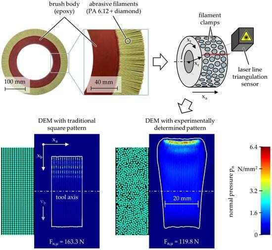
Nonetheless, to illustrate the relevance and benefit of accurately modeled filament patterns,
Figure 10 contrasts a square filament pattern—representing the state of the art prior to this article—with an interlocked pattern. The latter is modeled after the experimentally determined one in which the quasi-random arrangement of filaments encourages interactions.
Qualitatively, the square pattern yields vertical but separate filament traces without axial interactions. When compared to the interlocked pattern, axial interactions lead to the expected axial filament deflection shortly after the initial filament–workpiece contact as well as a subsequent homogenization of the filament traces. Quantitatively, the square pattern leads to a relative increase in the mean normal force of ∆Fn,µ = 36% and a relative decrease in the contact area of ∆Ac = 45% compared to the interlocked pattern. The identified differences are non-negligible deviations and emphasize that the established square pattern is not suitable for the DEM simulation of brushing processes.
4. Discussion
The described method, based on LLTS and image processing, proved suitable for experimentally determining the filament patterns of round brushes. Thereby, a high precision of Pc = 98% and a high recall of Rc = 99% could be achieved for brushing tools with a filament diameter of df = 1.1 mm. However, when tested on a brushing tool with a filament diameter of df = 0.6 mm, the recall Rc was notably lower, leaving 9% of filament clamps undetected. While higher recalls Rc could be achieved by fine-tuning the image processing parameters, the issue might be caused by the clamps of thin filaments being less circular, and thus, harder to detect regardless of the image processing. Hence, the cutting parameters of the AWIJC process need to be further investigated in order to obtain cleaner cuts.
Additionally, methods are currently being developed that do not rely on LLTS but on video cameras instead. This has the advantage of a simpler, less costly hardware setup but increases the pre-processing efforts because perspective, warp, and lighting need to be accounted for. It is also more robust towards an unwanted variability of the rotational speed of the motor, which complicates evaluation when using an LLTS because the circular filament clamps occasionally are distorted and become elliptical. Nonetheless, both methods provide the ability to track and count filaments, which is an essential improvement. Previously, the number of filaments Nf was approximated based on the total mass of filaments or extrapolated from filament counts in small sections of the brushing tools.
Subsequent DEM simulations using the experimentally determined filament patterns made it possible to calculate process forces, contact surface, and filament collisions. The mean normal force Fn,µ and the contact area Ac complied with the results from the technological investigations, thereby validating the DEM simulation. While the normal force Fn is an important parameter that can be directly linked to the work result—i.e., the material removal rate and the roughness reduction rate—the contact area Ac might also be relevant for the industrial process design. Especially, when surfaces are brushed in parallel paths, the contact area Ac would allow to calculate the ideal overlap of brushing paths required for homogeneous surfaces at maximum productivity. In addition, the simulation confirmed the expected results by demonstrating sweeping filament motions at low brushing velocity vb and high infeed ae, while also demonstrating striking filament motions at high brushing velocity vb and low infeed ae.
The DEM simulations suggested that at low brushing velocity vb, filament interactions occur shortly before initial workpiece contact, whereas at high brushing velocity vb, filament interactions occur after initial workpiece contact. Tendentially, filament interactions are limited to a small region around the contact surface but spread to the entire brushing tool at high brushing velocities vb. This dynamic behavior may potentially be undesired because it leads to inter-filament friction at high relative speeds, and consequently, the abrasion of the filaments. In practice, this problem is countered by using corrugated instead of straight filaments which are more likely to interlock. Therefore, simulations should also be carried out with corrugated filaments to determine the effects of this on filament interactions. In addition, simulations should be carried out involving industrial workpieces with complex shapes, such as gear wheels, roller bearings, and turbine blades.
As of yet, no experiments are achievable that could validate the simulated inter-filament collisions during brushing processes. One approach could be to utilize a high-speed camera to track filament motions, either on the front faces of the brushing tools or the filament tips by filming through a transparent workpiece. However, most filaments would remain occluded by other filaments. Another possible, although elaborate approach could be to analyze brushing experiments with computed tomography (CT). In particular, the abrasive grains that are bonded in the filaments could be detected with a CT scanner, tracked during brushing, and utilized to detect filament interactions. Unfortunately, both methods would yield only filament motions and collisions, but not any inter-filament forces.
While the description of mathematical filament pattern models was outside the scope of this article, it was shown that filament patterns can and should be modeled to reduce the efforts associated with AWIJC, LLTS, and image processing. Generally, different modeling approaches showed little effect on the simulated results as long as the filaments were sufficiently interlocked. In comparison, the square filament patterns that were used prior to this article led to large deviations of the mean normal force Fn,µ and the contact area Ac, making them unsuitable for the simulation of abrasive brushing processes.
5. Conclusions
In conclusion, the presented method, based on an innovative approach using LLTS and image processing, proved effective for experimentally determining the filament patterns of round brushes, offering high precision and recall for brushing tools with various filament diameters. DEM simulations, validated through compliance with technological investigations, provided insights into process forces, contact surface, and filament interactions, with implications for industrial process design. For example, costly technological investigations and prototypes could potentially be substituted by brushing simulations, especially if the DEM model were to be coupled with an experimental process model that correlates process forces with material removal rate and roughness reduction rate. Alternatively, the DEM model could be used to predict the dynamic behavior of the brushing tools, thereby reducing tool wear.
While challenges remain in validating simulated inter-filament collisions, ongoing developments in experimental techniques such as high-speed cameras and computed tomography offer promising directions for further research. Overall, modeling filament patterns is essential for reducing the complexities associated with abrasive brushing processes, with potential applications in various industrial sectors.


