Abstract
With the increasing demand for lightweight construction machinery, it is of great significance to study non-metallic materials that can replace steel plates to make hydraulic oil tanks (HOTs). To explore the feasibility of making HOTs with three materials—cross-linked polyethylene (XLPE), polypropylene (PP), and nylon (PA)—this paper takes 28 L and 115 L volumes commonly used in construction machinery, such as forklifts and loaders, as the design volume and obtains non-metal HOT products of good forming quality by regulating the process parameters. Based on the test methods and evaluation bases of the fuel tank in the national standard, the normal-temperature pressure test, high-temperature pressure test, and low-temperature impact test are designed according to the working conditions of the HOTs. Finally, the non-metallic HOT products are tested. The results show that the rotational molding of XLPE material is the easiest, and products of all sizes can be molded, but the mechanical properties and thermal stability of the products are poor. The low-temperature impact resistance of PP products is poor. PA material can be used to create small HOTs, and the product performance is excellent. This research serves as a valuable reference for the non-metallic and lightweight design of HOTs.
1. Introduction
The rapid development of construction machinery puts forward higher requirements for hydraulic technology. Lightweight development, miniaturization, integration, networking, and intelligence have become the main development trends of hydraulic components and systems [1]. The hydraulic oil tank (HOT) plays a crucial role in hydraulic systems by storing hydraulic fluid, separating gas and contaminants from the fluid, and regulating oil temperature. By weight, it is the largest component in hydraulic systems, accounting for over 40%, making it a key factor in system lightweight design [2]. Traditional HOTs are commonly made by welding steel or aluminum metal plates, but they suffer from drawbacks such as large volume, heavy weight, and low space utilization. Therefore, they are no longer preferred across various industries [1]. Compared to metals, non-metal materials have significant advantages in multiple aspects:
- (1)
- Low Density: Non-metal materials have a density of approximately 1/8 that of metal materials, resulting in significant reductions in weight and emissions for engineering machinery. This is conducive to the “dual carbon” strategy.
- (2)
- Corrosion Resistance: Engineering machinery often operates in harsh conditions. Compared to metal materials prone to rust and corrosion, non-metal materials exhibit highly corrosion-resistant properties, reducing the risk of component damage caused by corrosion [3].
- (3)
- Diversification: The integrated development of engineering machinery emphasizes high space utilization. Metal HOTs typically have rectangular shapes, reflecting the difficulty of shaping metal materials into diverse forms. Non-metal materials can easily be manufactured into containers of various shapes, greatly enhancing the spatial utilization of engineering machinery [4].
- (4)
- Simplified Process: Metal materials require multiple processes, such as stamping, welding, and rust prevention during the forming process, which can be complex. Non-metal materials, on the other hand, utilize simpler forming methods such as injection molding, rolling molding, and additive manufacturing, resulting in a much simpler process that is beneficial for cost reduction.
In recent years, some foreign companies, such as ARGO-HYTOS from Germany [5], MUNCIE from the United States, and FASSI from Italy, have developed non-metal HOT products. However, due to the protection of product competitiveness, there have been no reports on manufacturing processes, materials preparation, or tank performance. In China, there have been studies on miniaturizing HOTs [4,6], and some exploratory attempts have been made with non-metal HOTs [7]. However, there are no mature research cases yet. Nevertheless, there has been more in-depth exploration regarding non-metal fuel tanks, with demonstrative applications in areas such as automotive and engineering machinery [8,9]. It has shown excellent advantages in reducing costs, reducing weight, improving endurance, and in reverse design, which provides a reference for the development and exploration of non-metallic HOTs.
In the molding process, the fuel tank belongs to the liquid container, and the structure consists of only two parts: the inlet and the outlet. As hollow products, non-metallic fuel tanks are mostly produced by the blow molding or rotational molding process [10,11]. The HOT is also a hollow product but there is a need to install filters, air filters, level gauges, and other types of hydraulic accessories. Considering the flatness requirements and fastening requirements of the accessory installation, it is necessary to place metal inserts into the non-metallic HOT shell. Therefore, the trial production of non-metallic HOT molding has selected a rotational molding process that is more conducive to the molding of products with inserts.
In terms of materials, there are many kinds of plastics. The following two points should be considered when choosing which material to trial produce a non-metallic HOT:
- (1)
- Materials should be conducive to process molding. Powder materials must be used for rotational molding, among which polyethylene (PE) is the most studied and widely used material, accounting for 84 % of rotational molding materials. It is also the main material for making non-metallic fuel tanks. In addition, thermoplastic materials such as polypropylene (PP), nylon (PA), and polyvinyl chloride (PVC) also have many applications, accounting for 15% [12].
- (2)
- The material should meet the requirements of working conditions. The HOT is significantly different from the fuel tank. The internal medium of the HOT is constantly circulating, and the pressure loss of the hydraulic system during the working process is converted into heat energy and then brought back to the HOT through the circulating oil, resulting in a higher working temperature of the HOT, exceeding 80 °C [13]. At the same time, the HOT will also work under pressure; that is, it needs to bear a certain pressure, such as the closed HOT [14]. In addition, construction machinery also faces significant acceleration loads, such as sudden braking and vibration, which will affect the HOT.
Therefore, the selected non-metallic materials need to possess relatively good thermal stability, mechanical properties, and pressure resistance. Among numerous non-metallic materials, cross-linked polyethylene (XLPE), compared to ordinary polyethylene, has a unique cross-linked structure that provides higher thermal stability and mechanical strength, as well as better resistance to chemical corrosion and heat. PP has a density of approximately 0.90 g/cm3, making it one of the lightest general-purpose plastics while also exhibiting relatively excellent material strength and rigidity. PA materials can form hydrogen bonds between molecules, resulting in strong intermolecular forces, outstanding mechanical properties, and resistance to deformation. Therefore, the final selection consists of XLPE, PP, and PA for the trial production of non-metallic hydraulic oil tanks.
After the trial production is completed, the performance of the product needs to be verified. The working conditions of the HOT are complex, and non-metallic materials often exhibit lower mechanical and thermal properties compared to metals. Whether the non-metallic HOT products can meet the needs of use still needs to be tested. However, the survey found that there are no test schemes and test standards for HOTs in the current national and international standards.
In summary, based on the requirement of lightweight HOTs, this paper selects the commonly used 28 L and 115 L HOTs of construction machinery such as forklifts and loaders as the design volumes based on the rotational molding process, and three non-metallic materials, namely XLPE, PP, and PA, are chosen for the trial production of HOTs. The comparative analysis and research on the performance of the HOTs aim to provide technical support for the non-metallic HOTs, which is of great significance for the lightweight development, abnormality avoidance, and standardization of the HOTs.
2. Quality Analysis of Rotational Molding of the Non-Metallic HOT
2.1. Analysis of the Rotational Molding Process and Its Key Parameters
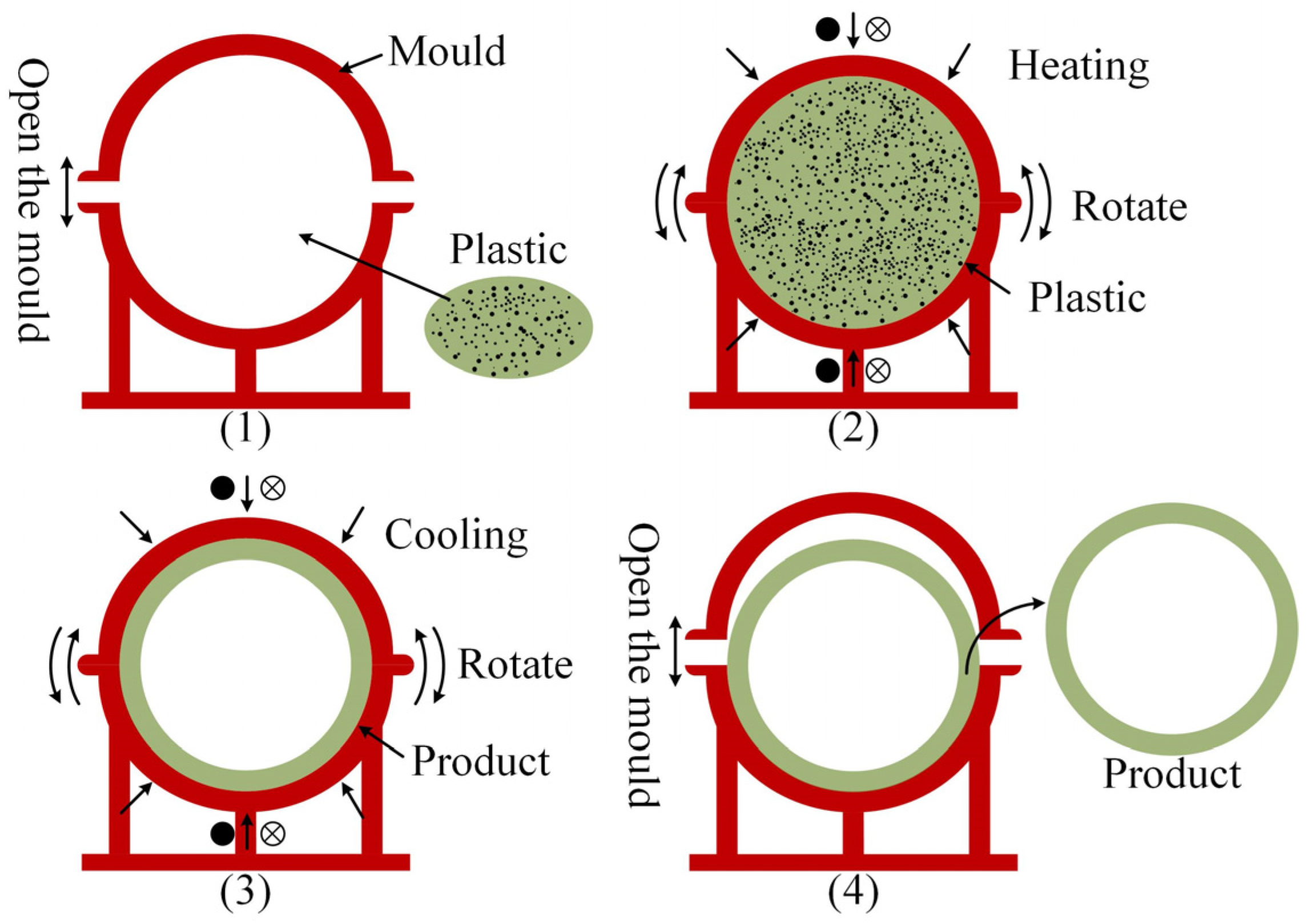
The rotational molding process involves adding powdered materials to the rotational molding mold so that the mold rotates around two axes while being heated. The internal materials are gradually melted and adhered to the mold due to heat and gravity. Finally, the mold is cooled and shaped, and the product is obtained after demolding [15,16]. The rotational molding process flow chart is shown in Figure 1.

Figure 1.
Rotational molding process flow chart.
The molding quality of rotational molding products is mainly affected by mold structure and process parameters. The structure of the mold depends on the structure of the product. Therefore, in the design of the HOT structure, not only the function of the HOT needs to be considered, but also the feasibility of the rotational mold and its process must be considered. The design part is not described in this paper due to space limitations.
Through the multi-component trial production test, it is found that the key process parameters affecting the molding quality of the HOT are as follows: spindle speed, auxiliary shaft speed [17], heating temperature, heating time [18], cooling method, and demolding temperature [19]. Among them, the main and auxiliary shaft speeds primarily affect the wall thickness uniformity of the product, with their parameter settings determined by the product’s structural size. The specific influence of other parameters varies. The following analysis is based on the trial production of large and small non-metallic HOTs. The following analysis is based on the trial production of two different non-metallic HOTs: one large and one small.
2.2. Analysis of the Rotational Molding Process and Its Key Parameters
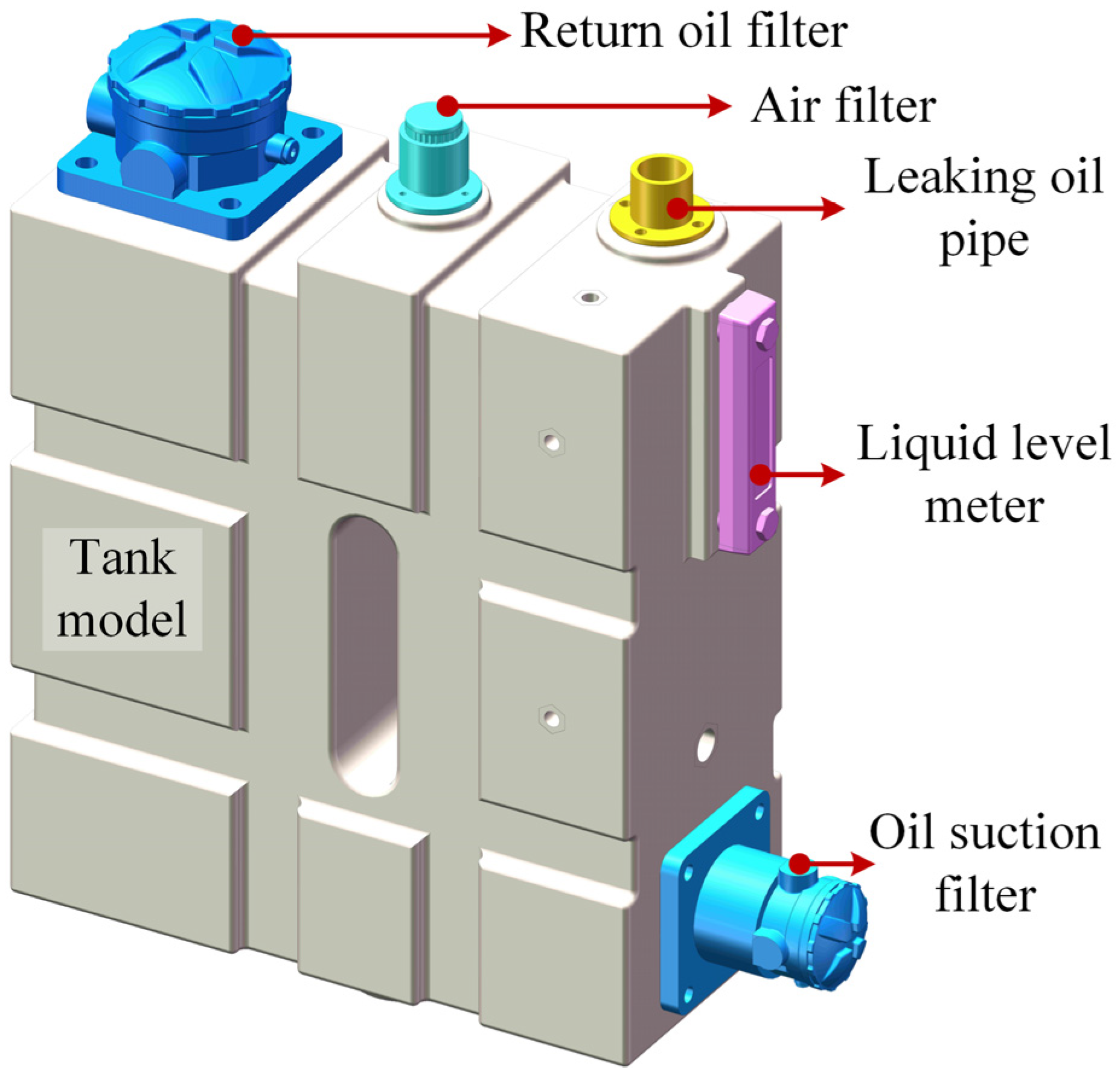
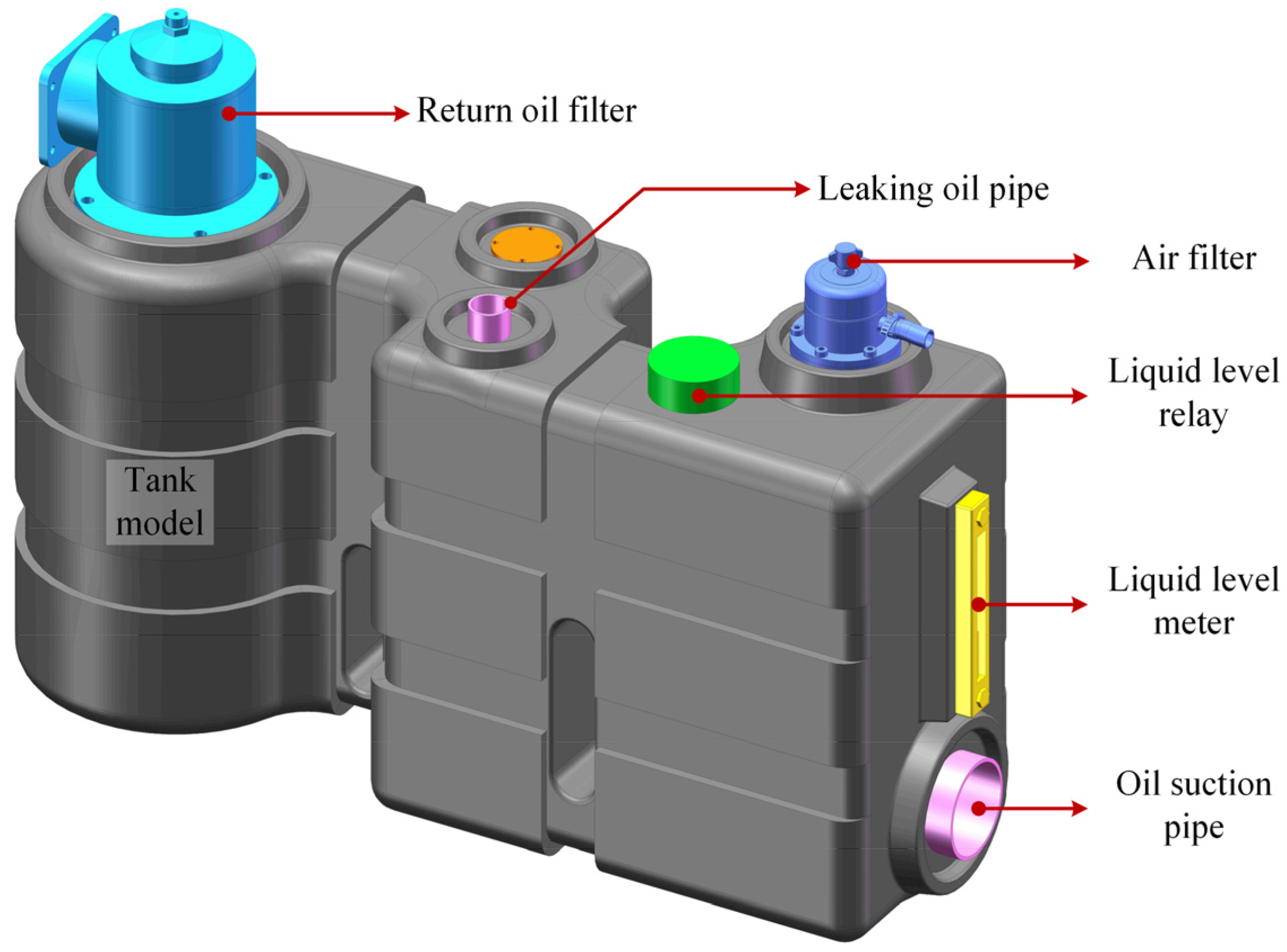
The non-metallic HOT with a volume of 28 L is designed to be 425 mm × 180 mm × 530 mm (length, width, and height), as depicted in Figure 2. Lightweight design principles necessitate minimizing the material used. By testing the tensile strength of each non-metallic material under various temperature conditions, the wall thickness is designed to be a minimum of 8 mm while still meeting the material’s yield strength requirements. Additionally, auxiliary parts such as an oil return filter, oil suction filter, air filter, level gauge, and leakage tubing are installed around the HOT.
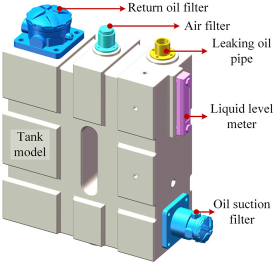
Figure 2.
The 28 L non-metallic HOT model.
The 28 L non-metallic HOT was trial-produced using XLPE, PP, and PA. The main parameters of each material are shown in Table 1. Comparing the three materials, it is observed that the density of PP is the smallest, resulting in relatively lighter HOT products under the same wall thickness. The tensile yield strength and flexural modulus of PA material are the largest, making it possess the best stiffness and strength properties. XLPE, on the other hand, offers the advantage of a low melting point, requiring less heat to convert the powder into a molten state. In addition, the Vicat softening points of all three materials are above the working temperature of the HOT, ensuring that the products will not soften during use. Based on the structure and size of the 28 L HOT, the spindle speed of the rotational mold is set to 9.0 r/min, with the auxiliary shaft speed set to 2.9 r/min. The forming process parameters and forming quality records of three kinds of materials under different process parameters are shown in Table 2, Table 3 and Table 4.

Table 1.
Material parameters.
Table 2.
Molding process parameters and quality of 8 mm thick 28 L XLPE HOT.
Table 3.
Molding process parameters and quality of 8 mm thick 28 L PP HOT.
Table 4.
Molding process parameters and quality of 8 mm thick 28 L PA HOT.
Heating time and temperature are process parameters that define the duration and temperature range from the start of heating in rotational molding until the plastic is completely melted. Cooling temperature and demolding temperature are process parameters that govern the material’s transition from the molten state to solid and then to demolding. Inadequate heating can result in incomplete melting of the powder, while excessive heating may cause the powder to overburn. Inadequate cooling can prevent proper molding of the products, while excessive cooling can make mold removal difficult. Hence, it is particularly crucial to determine the molding process window of the material, which refers to the range of process parameters within which the material can be effectively molded.
In addition, compared to air-cooled cooling, natural cooling has a slower cooling rate, resulting in a smaller temperature difference between the inside and outside of the product, thereby facilitating product molding. However, it takes longer to reduce the mold to the demolding temperature, thus extending the product’s molding cycle.
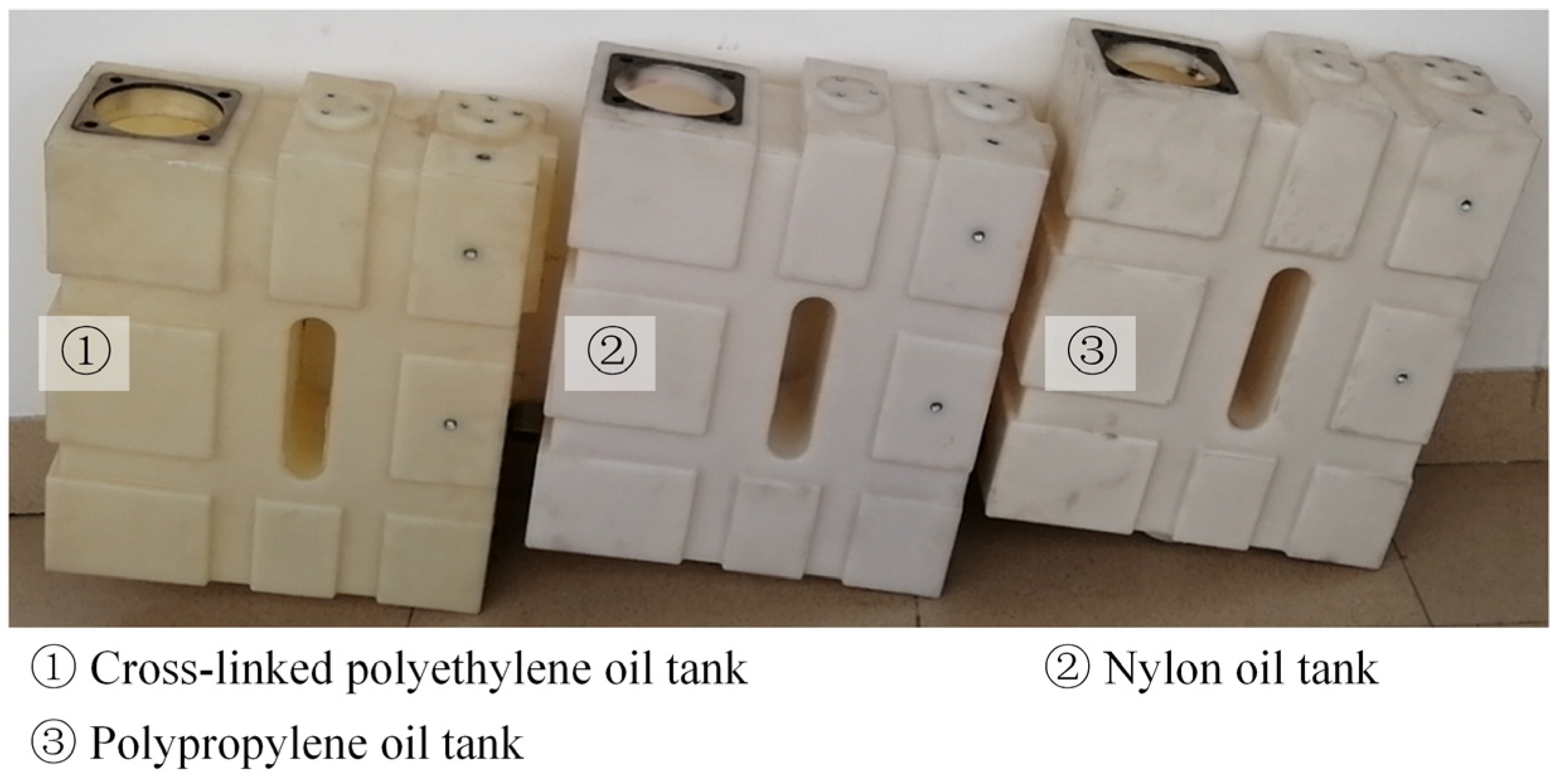
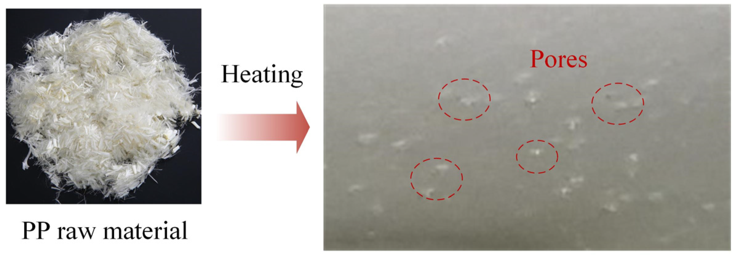
The 28 L non-metallic HOT products made of the three materials were successfully trial-produced, as depicted in Figure 3. However, there are still some pores present in the inner wall of the PP products that cannot be eliminated, as illustrated in Figure 4. The causes of pores in the products mainly include three points:
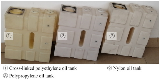
Figure 3.
The 28 L non-metallic HOT products.
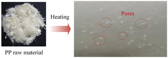
Figure 4.
The shape of PP raw material and the pore diagram inside the HOT product.
- (1)
- Incomplete heating of plastic powder;
- (2)
- Poor fluidity of plastic powder melt;
- (3)
- Plastic powder has a slender tail or hairy shape, and more air will be retained in the process of rotational molding [20].
Upon comparing the molding process parameters with the molding quality, it was found that during the second trial of PP products, overheating occurred, resulting in overburning. In the third trial production, the process parameters of the initial stage of the heating process were adjusted (prolonging the heating time by 1 min and reducing the heating temperature by 50 °C). However, despite these adjustments, pores were still observed in the products, indicating that the pores were not caused by incomplete heating of the plastic powder. On the other hand, the melt flow index of rotational molding materials is generally 2 to 10 g/10 min. Given the special shape of the selected PP raw material, a high melt flow index of 15 g/10 min, higher than the conventional PP raw material, was specifically chosen. Compared to other materials, this results in significantly higher melt flowability. Thus, reasons (1) and (2) are excluded. The PP powder used in this study has a filamentous shape, as shown in Figure 4. When heated, it causes a bridging phenomenon, trapping air. Therefore, it is concluded that the shape of the powder is an important factor causing pores on the inner walls of the PP HOT.
2.3. Analysis of the Rotational Molding Process and Its Key Parameters
The structure of the 115 L non-metallic HOT is depicted in Figure 5. It has overall dimensions of 1046 mm × 316 mm × 576 mm, with a wall thickness of 8 mm. Unlike the previous 28 L HOT, the 115 L non-metallic HOT has a larger volume and a more complex shape.
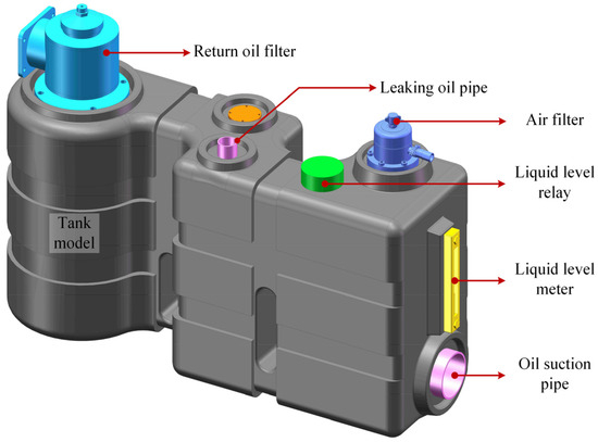
Figure 5.
The 115 L non-metallic HOT model.
Due to the high bubble rate and poor low-temperature impact resistance observed in the 28 L PP HOT (discussed below), the 115 L HOT was trial-produced using XLPE and PA materials, as listed in Table 1. The rotational speed of the main shaft is set at 6 r/min, while the rotational speed of the auxiliary shaft is 4.1 r/min for the rotational molding process. Additionally, considering the larger volume of the 115 L non-metallic HOT and the need to accommodate more powder, the heating time is appropriately extended, and the heating temperature is increased to ensure that the powder is fully heated. Hence, the heating stage is divided into three sections, with the addition of a preheating stage. The molding process parameters and molding quality records of the 115 L XLPE and PA HOT products are presented in Table 5 and Table 6.
Table 5.
Folding process parameters and quality of 115 L XLPE HOT with 8 mm thickness.
Table 6.
Molding process parameters and quality of 115 L PA HOT with 8 mm thickness.
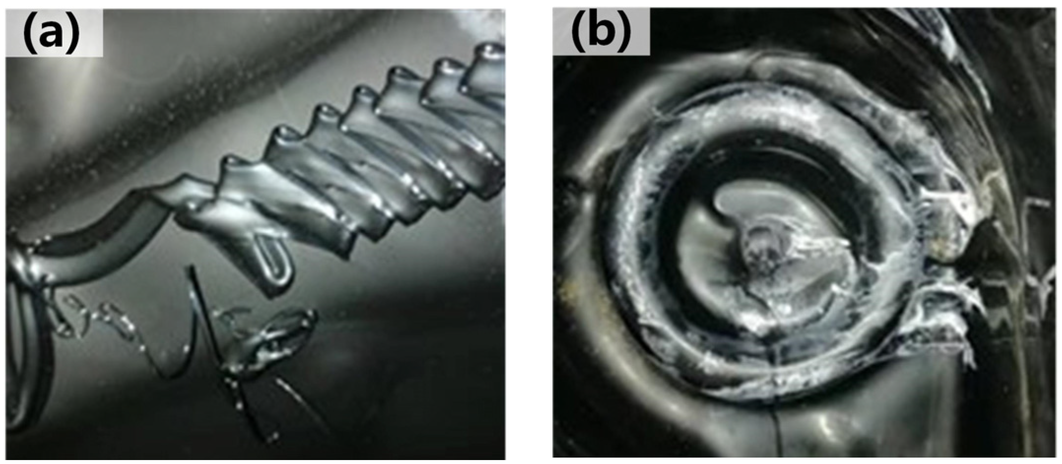
Through multiple process parameter controls, the molding quality of the 115 L XLPE HOT remains satisfactory, as depicted in Figure 6. However, the molding quality of the 115 L PA HOT did not meet the expected standard. The primary reason for this was the addition of PA powder, which resulted in a narrow molding window for the material and high fluidity in the molten state. When the outer side of the product has reached the demolding temperature, the material inside the product is not completely solidified, leading to the phenomenon of raw material stacking, as shown in Figure 7a. If the product is fully cooled, the PA material becomes hard and brittle, making the product prone to cracking upon mold removal. Additionally, the PA material is sensitive to process parameters during the heating stage. Excessive heating can result in white stripes on the inside of the product, as shown in Figure 7b. In summary, the process window of the XLPE material is wide, and the difficulty of rotational molding is the lowest. On the other hand, the PA material is challenging to shape, and improper setting of heating and cooling parameters can result in white stripes and stacking of products. The molding difficulty of the PP material falls between the two, and the shape of its powder results in pore defects on the inner wall of the product. Furthermore, when using a rotational molding process, the molding difficulty of the non-metallic HOT is significantly constrained by its volume. When the HOT is small, all three materials can be molded. However, for larger product volumes, the XLPE material can still be shaped effectively, whereas shaping the PA material becomes more challenging.
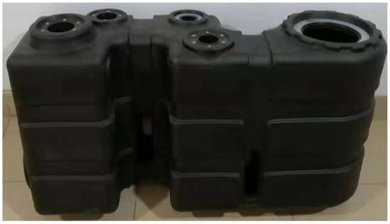
Figure 6.
The 115 L XLPE HOT products.

Figure 7.
Molding quality of 115 L PA HOT. (a) Stacking; (b) White stripe.
3. Performance Test Scheme of the Non-Metallic HOT
In the application process of HOTs, it is necessary to store and regulate high-temperature and high-pressure hydraulic oil, as well as withstand the vibrations and impacts of construction machinery under various working conditions. Hence, assessing the performance of a HOT made of non-metallic materials under typical working conditions is crucial for determining its qualification.
Currently, there are no specific test specifications for HOTs in national and international standards. However, the test standards for fuel tanks are relatively comprehensive. According to the different working conditions, they can be divided into GB 18296-2019 “Safety Performance Requirements and Test Methods for Automobile Fuel Tanks and Their Installations”, GB/T 25608-2017 “Performance Requirements for Non-metallic Fuel Tanks of Earthmoving Machinery”, GB 24930-2010 “Safety Performance Requirements and Test Methods for All-terrain Vehicle Fuel Tanks”, etc. Therefore, based on the national standard for fuel tanks and the working conditions of HOTs, this paper formulates the test scheme for non-metallic HOTs for the first time. This scheme includes normal-temperature pressure tests, high-temperature pressure tests, and low-temperature impact tests.
3.1. Equipment and Instruments
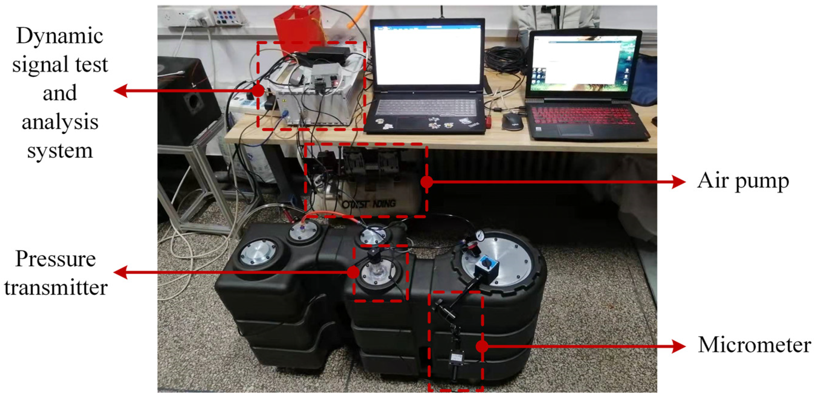
Data acquisition instruments include dynamic signal test and analysis systems (Model: DH5922D, measuring range: ±100 mV~±10 V multistage switching), pressure transmitter (Model PCM300, measuring range: 0~40 kPa, accuracy: 0.5% FS), temperature sensor (Model PCT300, measuring range: −50~150 °C, accuracy: 0.5% FS), percent micrometer (Model CW-141, measuring range: 0–50.8 mm, accuracy: 0.02 mm), air pump and pressure regulating valve.
3.2. Preparation of Test Plan
- (1)
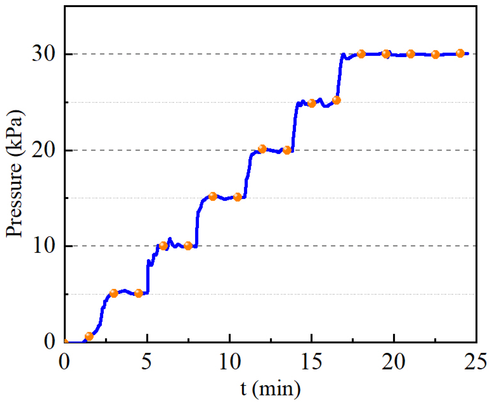
- Normal temperature pressure test method: The ambient temperature pressure test involves injecting water at 20 °C to 80% of the HOT’s volume. Once all inlets and outlets of the HOT are sealed, the HOT is filled with gas. The test device is depicted in Figure 8. The pressure is maintained in the range of 0–30 kPa, with a 2-min duration for each 5 kPa increment. Once the pressure reaches 30 kPa, it is held until the deformation stabilizes. The internal pressure gradient of the HOT is illustrated in Figure 9, with a pressure error of less than 0.3 kPa. Then, proceed to check and record any leakage as well as the maximum deformation of the HOT.
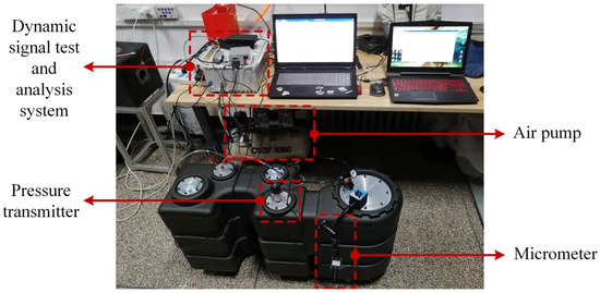 Figure 8. Pressure test devices.
 Figure 9. Internal pressure time curve of the HOT for pressure test.
 - (2)
- High-temperature pressure test method: At an ambient temperature of 20 °C, 80 % of the volume of water at 80 °C is injected into the HOT. All inlets and outlets of the HOT are sealed, and gas is then filled into the HOT. The test device is depicted in Figure 8, and the pressure gradient is shown in Figure 9. Proceed to check and record any leakage as well as the maximum deformation of the HOT.
- (3)
- Low-temperature impact test method: The empty HOT is placed in an environment with a temperature of −15 °C for 12 h. Subsequently, it is subjected to free fall, with air resistance ignored. The impact energy of the HOT is controlled to be 90 J. The calculation formula for the height between the impact point of the HOT and the impact plane is shown in Equation (1). Proceed to impact each corner of the HOT and then check and record any damage.
Here, h is the height from the impact point to the impact plane, W is the impact energy, m is the HOT quality, and g is the gravitational acceleration.
4. Comparison of Test Performance of the Non-Metallic HOT
4.1. Test Results of 28 L Non-Metallic HOT
The deformation time curve of the XLPE HOT for the pressure test is shown in Figure 10. As can be seen from Figure 9, when the internal pressure of the HOT remains unchanged, its deformation still increases gradually. To facilitate the comparison of deformation results among the HOT materials, deformation less than 0.1 mm within 5 min is considered the evaluation standard for achieving a stable state.
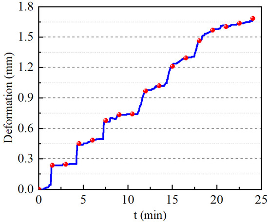
Figure 10.
Pressure test deformation time curve of XLPE HOT.
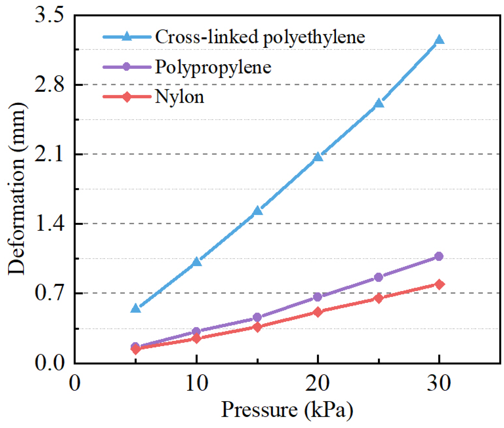
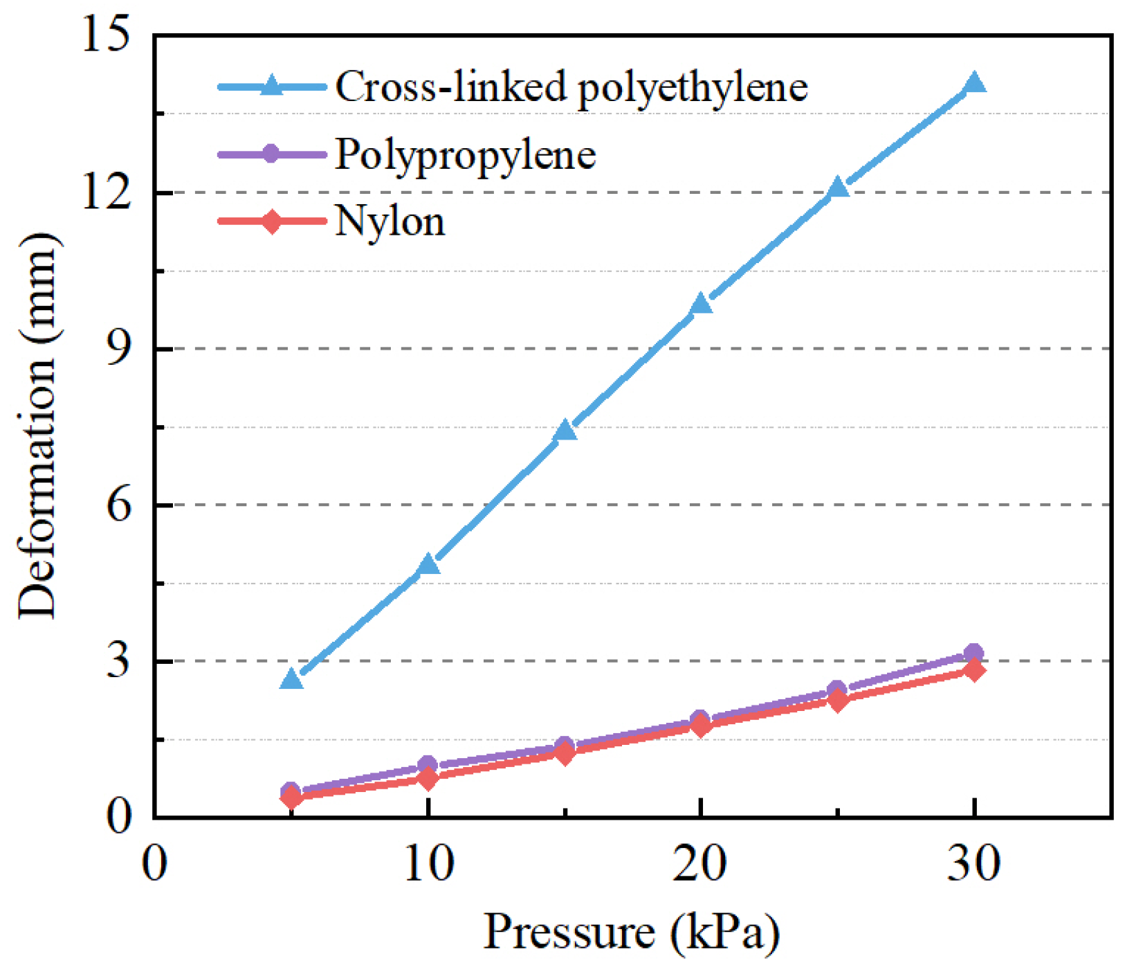
During the ambient temperature pressure test, none of the three types of non-metallic HOT products exhibited any leakage. The deformation data of the HOT under various pressure conditions were extracted and plotted to generate curves representing the results of the pressure resistance test at normal temperature, as depicted in Figure 11. At an internal pressure of 30 kPa, with stable deformation, the maximum deformations of the 8 mm thick XLPE, PP, and PA HOTs are 3.243 mm, 1.072 mm, and 0.794 mm, respectively. The results indicate that the ambient temperature pressure conditions and the pressure resistance of XLPE products are the poorest among the three, with the highest risk of leakage, followed by PP products. Due to the presence of polar amide groups in the repeating units of PA molecules, which can form intermolecular hydrogen bonds, the intermolecular interaction forces of PA products are relatively strong, resulting in the best mechanical properties and minimal compressive deformation [21].
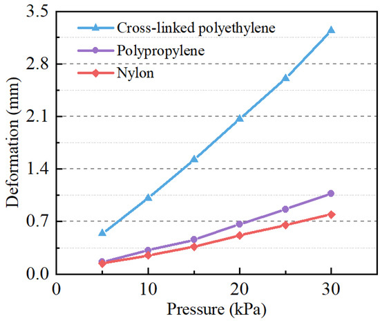
Figure 11.
Results of ambient temperature pressure test of 28 L non-metallic HOT.
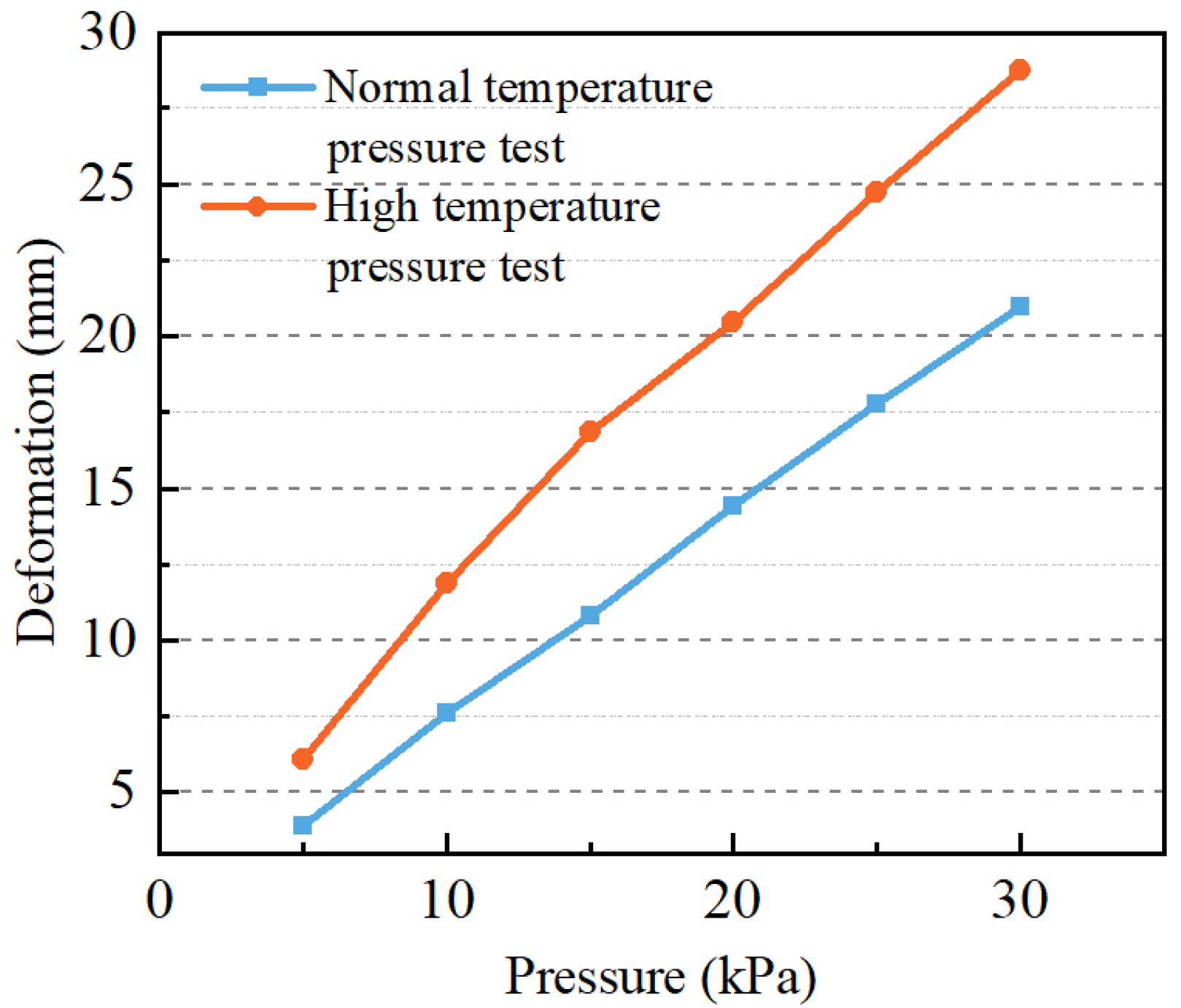
During the high-temperature pressure test, none of the non-metallic HOTs made of the three materials showed any leakage. The test results are depicted in Figure 12. At an internal pressure of 30 kPa and a stable product deformation at 80 °C, the maximum deformations of the 8 mm thick XLPE, PP, and PA HOTs are 14.061 mm, 2.831 mm, and 3.149 mm, respectively. The results indicate that under high-temperature conditions, the mechanical properties of cross-linked polyethylene products are the poorest. This is because the molecules of polyethylene material consist of linear molecular chains. As the temperature increases, the binding force (van der Waals force) between the linear molecular chains weakens, leading to the deformation of the entire molecular material, hence poor temperature resistance [22]. The mechanical properties of the PP products are closer to those of nylon products.

Figure 12.
High-temperature pressure test results of 28 L non-metallic HOT.
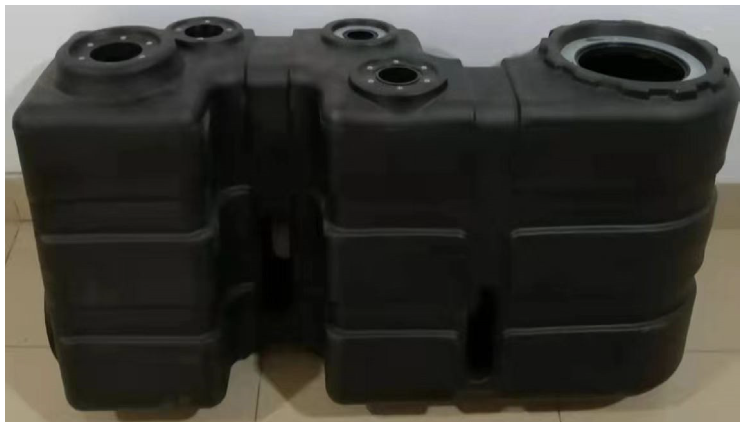
By comparing the results of the two tests, it is evident that the maximum deformation of the XLPE, PP, and PA products increased by 33 4%, 194 %, and 257 %, respectively. This indicates that the PP products exhibit the best thermal stability among the three materials when the temperature is between 20 °C and 80 °C, followed by PA materials, while XLPE products exhibit the worst thermal stability. The weights of the 8 mm thick XLPE, PP, and PA HOTs are 6.1 kg, 5.9 kg, and 6.6 kg, respectively. The height of the impact point of the low-temperature impact test can be calculated using Equation (1) as 1.51 m, 1.56 m, and 1.39 m, respectively. After the test, the HOT of the XLPE and PA materials did not show any obvious damage, while the PP HOT was smashed, as depicted in Figure 13. This is due to the relatively poor flexibility of the molecular chains of the PP material, which exhibits inferior low-temperature toughness compared to XLPE and PA materials, making the PP material-based HOT less resistant to low temperatures and unsuitable for use under such conditions [23].
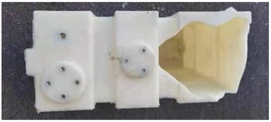
Figure 13.
Low-temperature impact test results of 28 L PP HOT.
4.2. 115 L XLPE HOT Test
A pressure resistance test at both ambient temperature and high temperature was conducted for 8 mm-thick 115 L XLPE HOT products. No leakage occurred during the test, and the maximum deformation result is shown in Figure 14. The maximum deformation of the HOT is 20.987 mm when the internal pressure of the withstand test at ambient temperature is 30 kPa, and the deformation is stable. When the internal pressure of the high-temperature pressure test is 30 kPa, and the deformation is stable, the maximum deformation of the HOT is 28.736 mm. The accumulated deformation on both sides of the HOT is close to 20 % of its width, indicating that using the XLPE material to manufacture a large volume of the HOT will pose a significant deformation problem. This not only increases the risk of leakage but also greatly impacts the arrangement of the pump, motor, and other hydraulic components.
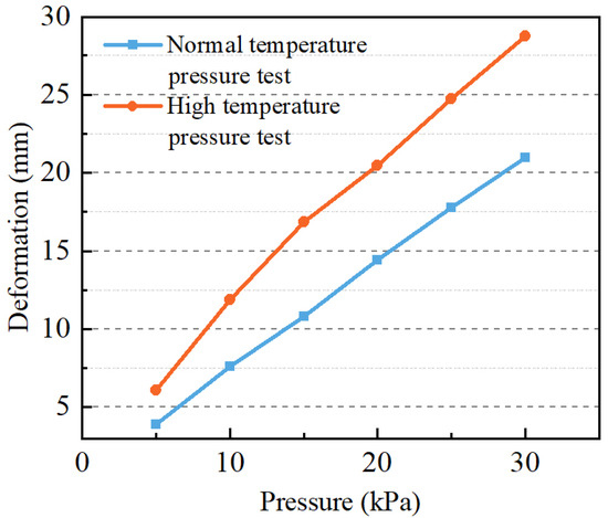
Figure 14.
Pressure test results of 115 L XLPE HOT.
The weight of the 115 L XLPE HOT with a thickness of 8 mm is 19.0 kg. According to Equation (1), the height from the impact point on the ground is 0.48 m. After the test, the product remains undamaged.
5. Comparison of Test Performance of Non-Metallic HOT
In this paper, a 28 L XLPE, PP, and PA HOT and a 115 L XLPE and PA HOT were trial-manufactured based on the rotational molding process. Based on relevant fuel tank standards, schemes for normal temperature pressure tests, high-temperature pressure tests, and low-temperature impact tests of non-metallic HOTs were designed. Subsequently, the tests were conducted. The summary of research findings and research recommendations for the industry is as follows:
- (1)
- The scheme for molding a non-metallic HOT using the rotational molding process is feasible. The molding quality of a non-metallic HOT is closely related to material properties and process parameters. While XLPE material is easy to mold, its poor mechanical properties necessitate caution to avoid difficulties during demolding or even product damage caused by excessive cooling. The PA material has a narrow forming window and excessively high flowability, making it challenging to mold large products. It is necessary to adjust the heating stage process parameters to reduce the temperature difference between the inner and outer sides of the material. The shape of PP powder makes it difficult to eliminate bubbles during the molding process, resulting in air holes on the inner wall of the molded products.
- (2)
- A test scheme for evaluating the performance of a non-metallic HOT is proposed. The test results indicate that the mechanical properties of PA material are the best, while those of XLPE material are the worst. The deformation of XLPE products in both the ambient temperature pressure test and the high-temperature pressure test is the largest, significantly surpassing that of the other two materials. In addition, comparing the results of the two experiments, it can be proven that the thermal stability of cross-linked polyethylene is also the poorest among the three. Ultimately, the PP products were crushed at a temperature of −15 °C under an impact energy of 90 J, confirming their poor low-temperature resistance and unsuitability for use in low-temperature environments.
Based on the research findings, scholars and researchers can choose suitable materials for non-metallic HOTs according to their application scenarios and specifications to avoid potential defects. In the future, we will continue to focus on the research of lightweight and miniaturized non-metallic HOTs, propose new methods for the structural and volumetric design of HOTs, and adapt to the trend of non-metallic development in hydraulic containers, making the application of non-metallic materials in this field more mature.
Author Contributions
Conceptualization, Z.H. and F.Z.; methodology, Z.H. and F.Z.; software, Z.H., C.T., X.C. and T.C.; validation, C.T. and T.C.; formal analysis, F.Z. and P.M.; investigation, X.C. and T.C.; resources, F.Z. and P.M.; data curation, Z.H., C.T., X.C. and T.C.; writing—original draft preparation, Z.H. and T.C.; writing—review and editing, Z.H. and F.Z.; visualization, C.T.; supervision, F.Z. and P.M.; project administration, F.Z.; funding acquisition, F.Z. and P.M. All authors have read and agreed to the published version of the manuscript.
Funding
This research was funded by the National Key R&D Program of China, grant number SQ2018YFB200029.
Data Availability Statement
Data are contained within the article.
Conflicts of Interest
The authors declare no conflicts of interest.
References
- Kong, X.; Zhu, Q.; Yao, J.; Shang, Y.; Zhu, Y. Basic theory and key technology of “new method for lightweight design and manufacturing of hydraulic components and systems”. Chin. J. Mech. Eng. 2021, 57, 4–12. [Google Scholar]
- Yang, H. Preface. Chin. J. Mech. Eng. 2021, 57, 1–3. [Google Scholar]
- Krawczyka, R.; Słaniaa, J.; Golańskia, G.; Nawrockib, J. Analysis of the reasons for crack in a tank of the hydraulic system. Eng. Fail. Anal. 2020, 116, 104716. [Google Scholar] [CrossRef]
- Yao, J.; Liu, X.; Li, M.; Kong, D.; Hu, J. Design and characteristic analysis of miniaturized labyrinth hydraulic reservoir. Chin. J. Mech. Eng. 2021, 57, 83–92. [Google Scholar]
- ARGO-HYTOS Hydraulic Fluid Solutions Home Page. Available online: https://www.argo-hytos.com/products/tank-solutions.html (accessed on 27 February 2024).
- Zhai, F.; Li, C.; Ye, Z.; Tan, C.; Chen, Y. Influence of built-in filter boundary on flow field in miniaturized hydraulic tank. Chin. J. Mech. Eng. 2021, 57, 114–122. [Google Scholar]
- Yin, J.; Quan, X.; Wu, D. Structure and Heat Dissipation Design of Carbon Fiber Hydraulic Tank. Electro-Mech. Eng. 2023, 39, 32–36. [Google Scholar]
- Bruak, U.; Sena, A.; Gokay, S.; Erdem, A.; Vedat, D.; Zahit, M.; Halti, T.; Serter, A. Static and dynamic analysis of plastic fuel tanks used in buses. Procedia Eng. 2015, 101, 509–517. [Google Scholar]
- Tan, M.; Lin, B.; Sun, P.; Liang, H. Research and development of rotational molding fuel tank for excavators. Constr. Mach. Equip. 2017, 48, 1–7. [Google Scholar]
- Shafigullin, L.; Sotnikov, A.; Romanova, N.; Shabaeva, E.; Sarimov, D. Development of a polymeric fuel tank with high barrier properties. IOP Conf. Ser.-Mater. Sci. Eng. 2019, 570, 1–7. [Google Scholar] [CrossRef]
- Azizeh-Mitra, Y.; Haile, A. Modeling of complex parison formation in extrusion blow molding: Effect of medium to large die heads and fuel tank geometry. Polym. Eng. Sci. 2009, 49, 229–239. [Google Scholar]
- Ogila, Y.; Shao, M.; Yang, W.; Tan, J. Rotational molding: A review of the models and materials. Express Polym. Lett. 2017, 11, 778–798. [Google Scholar] [CrossRef]
- Zhang, K.; Gu, Z.; Feng, K.; Quan, L. Modeling and simulation analysis of thermal balance of excavator hydraulic. Chin. Hydraul. Pneum. 2021, 45, 100–107. [Google Scholar]
- Zhao, D.; Jia, T.; Cui, Y. Design and constant pressure characteristics of a ship-borne pressure tank. J. Tsinghua Univ. (Sci. Technol.) 2019, 59, 306–313. [Google Scholar]
- Gupta, N.; Ramkumar, P.; Sangani, V. An approach toward augmenting materials, additives, process ability and parameterization in rotational molding: A review. Mater. Manuf. Process. 2020, 35, 1539–1556. [Google Scholar] [CrossRef]
- Lumirca Del Valle Espinoza, L.; Viviane Alves, E.; Leila Lea Yuan, V.; Julio Cesar, J.; Elen Beatriz Acordi Vasques, P. Rotomolding and polyethylene composites with rotomolded lignocellulosic materials: A review. J. Reinf. Plast. Compos. 2020, 39, 459–472. [Google Scholar]
- Mahsa, D.; Taher, A.; Mohamad, K.; Milad, M. Investigation of tensile properties of polymeric nanocomposite samples in the rotational molding process. Polym. Bull. 2021, 78, 2465–2481. [Google Scholar]
- Wang, X.; Wang, K.; Sun, X.; Chen, X.; Liang, W. Analyses on equivalence of time-temperature during heating cross-linked polyethylene in rotation molding. Plastics 2017, 32, 50–57. [Google Scholar]
- Chandran, V.G.; Waigaonkar, S.D. Rheological and dynamic mechanical characteristics of rotationally moldable linear low-density polyethylene fumed silica nanocomposites. Polym. Compos. 2016, 37, 2995–3002. [Google Scholar] [CrossRef]
- Xu, H.; Xu, Y.; He, J.; Xiao, D.; Zhao, H.; Wu, J.; Liu, S. Investigation and solution of defects on plastic products by rotational molding processing. Eng. Plast. Appl. 2017, 35, 40–44. [Google Scholar]
- Ali Reza, Z.; Shokoufeh, H.; Hamed, A. Rheological, mechanical and thermal properties of the PA/PVB blends and their nanocomposites: Structure-property relationships. Polym. Test. 2018, 66, 48–63. [Google Scholar]
- Reylina, T.; Mark, M.; Allysa, O. A review of the factors that influence aging and degradation in crosslinked polyethylene (XLPE) polyolefin. Mater. Today Proc. 2023, 10, 95. [Google Scholar]
- Wu, B.; Li, Y.; Yang, J.; Zhou, Y. Mechanism of low-temperature brittle–ductile transition of polypropylene/low-density polyethylene blend foam under compressive stress caused by cell stretching. Adv. Eng. Mater. 2023, 25, 2300533. [Google Scholar] [CrossRef]


Disclaimer/Publisher’s Note: The statements, opinions and data contained in all publications are solely those of the individual author(s) and contributor(s) and not of MDPI and/or the editor(s). MDPI and/or the editor(s) disclaim responsibility for any injury to people or property resulting from any ideas, methods, instructions or products referred to in the content. |
© 2024 by the authors. Licensee MDPI, Basel, Switzerland. This article is an open access article distributed under the terms and conditions of the Creative Commons Attribution (CC BY) license (https://creativecommons.org/licenses/by/4.0/).