Article

Design of Active Suspension Controller for Ride Comfort Enhancement and Motion Sickness Mitigation

Department of Mechanical and Automotive Engineering, Seoul National University of Science and Technology, 232 Gongneung-ro, Nowon-gu, Seoul 01811, Republic of Korea
*
Author to whom correspondence should be addressed.
Machines 2024, 12(4), 254; https://doi.org/10.3390/machines12040254
Submission received: 19 March 2024 / Revised: 3 April 2024 / Accepted: 10 April 2024 / Published: 11 April 2024
(This article belongs to the Special Issue Optimal Control of Autonomous Vehicles)

Abstract

:
This paper presents a method for designing an active suspension controller for ride comfort enhancement and motion sickness mitigation. For this, it is necessary to design an active suspension controller, which aims to reduce the vertical acceleration and pitch rate of a sprung mass in a vehicle. A half-car vehicle model was selected. For the controller design, a static output feedback (SOF) control was selected instead of a full-state feedback control because it is hard to measure all state variables in real vehicles. With the available signals, three types of SOF controller were proposed. To determine the gains of the SOF controllers, a linear quadratic optimal control methodology and a simulation-based optimization method were adopted. To validate the proposed method, a simulation was carried out using vehicle simulation software. The simulation results show that the proposed method is quite effective for ride comfort enhancement and motion sickness mitigation.

1. Introduction

Currently, there are two objectives in suspension design and control: ride comfort and road handling. The measures used to evaluate these objectives are heave acceleration, suspension stroke, and tire deflection [1]. Figure 1 shows the frequency weightings representing the sensitivity of the human body to vibration, specified in ISO2631-1 [2]. According to ISO2631-1, the frequency ranges that human bodies are considered to be most sensitive to are near 0.2 Hz for motion sickness and 4~10 Hz for vertical acceleration. For this reason, the heave acceleration of a sprung mass near 0.2~0.5 Hz and in the 4–10 Hz range should be reduced for motion sickness mitigation and ride comfort enhancement, respectively [3].
Over the last decade, autonomous driving has been intensively studied because it can prevent several types of traffic accidents, as well as improving road safety and traffic flow [4]. However, autonomous vehicles can cause severe motion sickness due to passengers being able to carry out non-driving tasks, such as reading a book [5]. Motion sickness is caused by mismatch between accelerations measured from visual sensing and vestibular systems. Without external visual sensing, motion sickness is caused by the sensory conflict between estimated and measured accelerations in a vestibular system. Figure 2 shows the effects of frequencies for several accelerations on motion sickness [6]. According to Figure 2, motion sickness is caused by a vibration with a maximum amplitude of 3.2 m/s2 in a frequency range of 0.2~0.5 Hz for the vertical, front, and aft directions from a car. More specifically, it was reported that the highest percentage of vomiting occurred at 0.167 Hz [7], obtained from 500 subjects seated with their heads against a backrest and their eyes open in an enclosed cabin that oscillated vertically. However, those results were obtained from a ship. Motion sickness caused by the vertical oscillation of a passenger car has rarely been investigated.
Recent studies on motion sickness for a passenger car showed that when reading in a car, there is significant risk of motion sickness caused by combined heave acceleration, pitch, and roll rates in the 0.8~8 Hz range [8,9]. This differs from the information given in Figure 1 and Figure 2, since this is mainly derived from vertical motion of a ship. Based on this fact, reducing the vertical vibration within the frequency band of 0.8~8 Hz was shown to be effective for mitigating motion sickness while reading a book or looking at a display device in a car. Among the heave, roll, and pitch motions of the sprung mass, it was shown that the roll rate had little effect on motion sickness [10]. For this reason, it is necessary to reduce the heave acceleration and pitch rate of the sprung mass in the 0.8~8 Hz range for ride comfort enhancement and motion sickness mitigation.
Several actuators have been proposed and developed for vehicle suspension control, such as active suspension, continuous damping control, magneto-rheological dampers and air springs, etc. In this paper, active suspension is adopted for the purpose of reducing the vertical and pitch vibrations within the frequency range of 0.8~8 Hz. There have been many studies on active suspension control for ride comfort and road handling [11,12]. In controller design, a quarter-car, half-car, and full-car linear model were selected [12]. In this paper, a half-car model is selected because it can be used to fully describe the heave acceleration and the pitch rate of a sprung mass. From a half-car model, a state–space equation is derived and used for the controller design.
For active suspension control, several methodologies, such as linear optimal, H, nonlinear, and adaptive control theories, have been proposed and applied [1,11,12,13]. Among them, linear quadratic control (LQR) has been widely selected as a controller design methodology. However, LQR is a full-state feedback controller, which requires all states to be measured or estimated. This is quite difficult in a real vehicle. To cope with this problem, static output feedback (SOF) control is adopted in this paper [14,15]. In a previous study, a full-car model, requiring 56 gain elements for LQR, was controlled by the LQ SOF controller with two gain elements [15]. In this way, an SOF controller can significantly reduce the number of gain elements needed for feedback controller. In this study, the heave velocity, pitch rate, and front/rear suspension velocity were selected as available outputs for SOF control. These variables can be obtained by integrating accelerometer signals measured at the front/rear corners of a sprung mass and wheel centers. With those signals, three types of controller structure for SOF control are proposed in this paper.
To find the optimum gain of the SOF controller, two methods are adopted in this study. The first uses linear quadratic optimal control (LQOC), which employs a state–space equation derived from a half-car model and an LQ objective function. Generally, a spring and a damper in a suspension system are nonlinear. If there is a nonlinear element in a vehicle model, LQOC cannot be applied to controller design. Instead of LQOC, the second method uses a simulation-based optimization method (SBOM) [16,17,18]. In an SBOM, a vehicle model with nonlinear elements is built in MATLAB/Simulink. From a simulation with the model over a period, several variables can be obtained and used to evaluate an objective function [18]. Both methods formulate the SOF controller design as an optimization problem. To solve the optimization problem, the heuristic optimization method, a covariance matrix adaptation evolution strategy (CMA-ES), is adopted [19].
The aim of this study is to design SOF active suspension controllers with LQOC and SBOM for ride comfort enhancement and motion sickness mitigation. For this purpose, three types of controller structure for SOF control were proposed and optimized by LQOC and SBOM. To validate the controllers designed by LQOC and SBOM, a simulation was conducted using the vehicle simulation software, CarSim. From the simulation results, the best controller for ride comfort enhancement and motion sickness mitigation was identified.
The contributions of this paper can be condensed as follows:
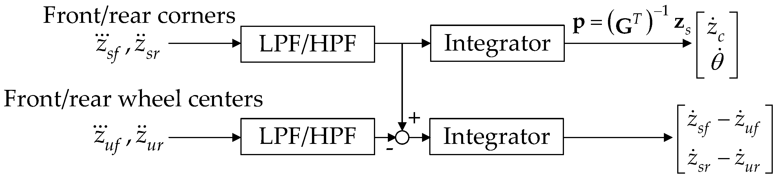
  • Three types of controller structures for SOF control are presented. As an available output for SOF control, the heave velocity, pitch rate and front/rear suspension velocity were selected.
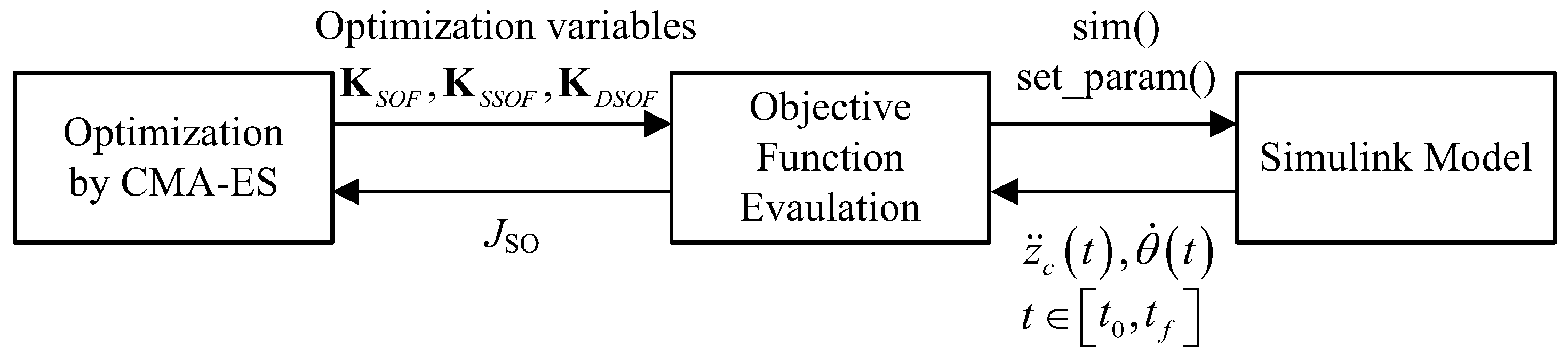
  • To find the optimum gain elements of the SOF controllers for nonlinear vehicle models, SBOM was adopted. A Simulink model for a nonlinear vehicle was built and used for SBOM.
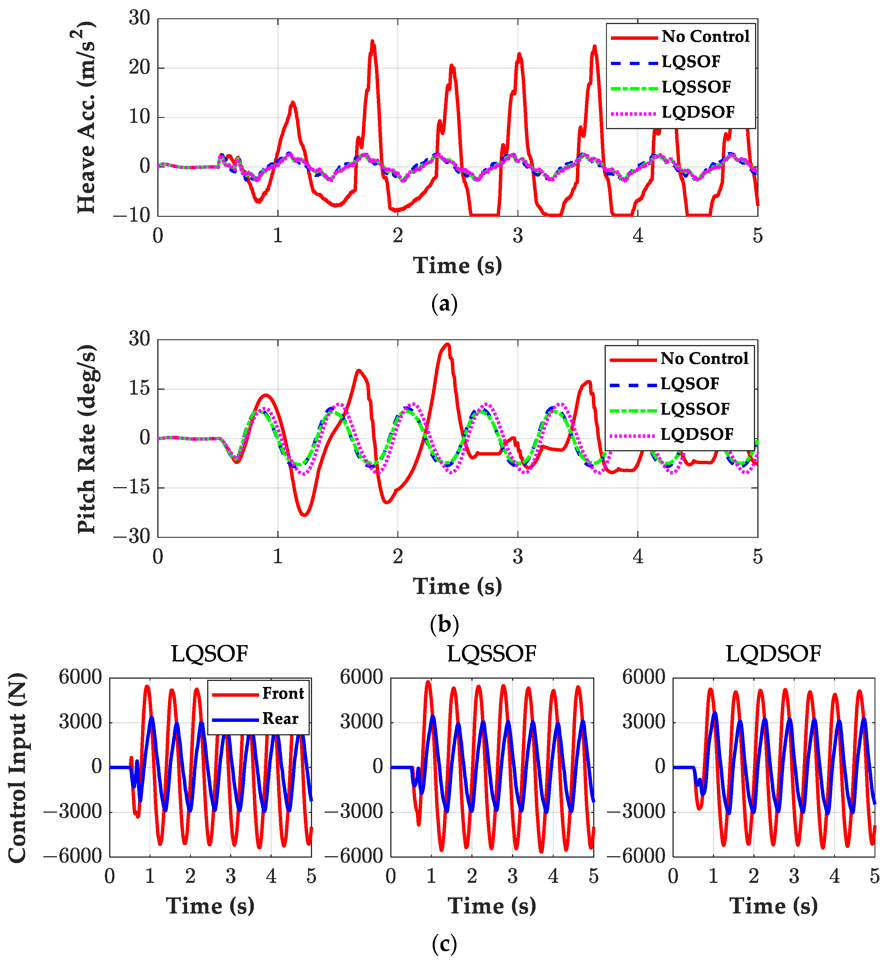
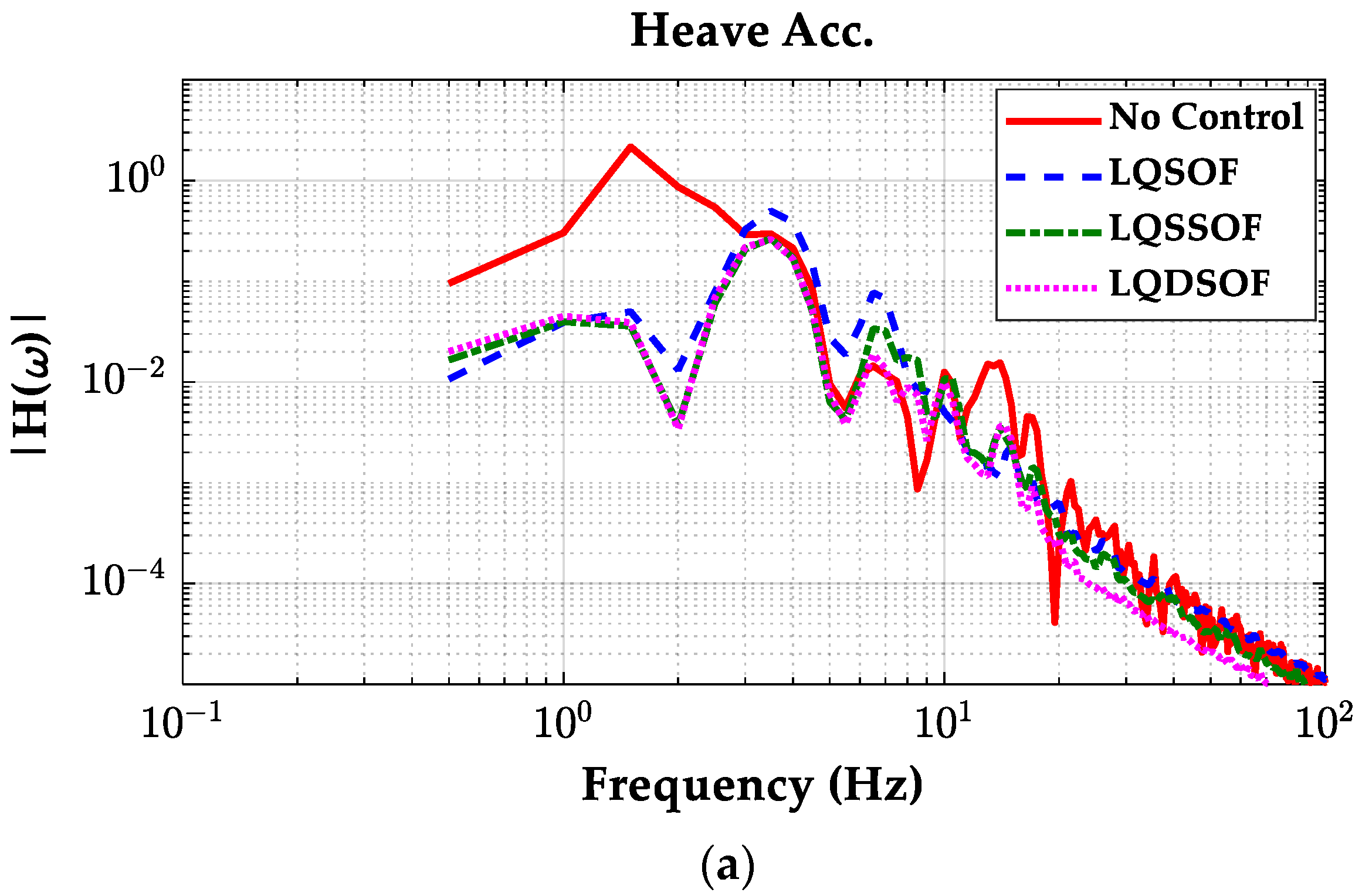
  • A Simulation was conducted on vehicle simulation software, CarSim. From the comparison results, the best SOF control structure for ride comfort enhancement and motion sickness mitigation was identified.
This paper consists of four sections. A design procedure for three SOF controllers is described in Section 2. A Simulation was conducted, and its results were discussed in terms of the performance measures described in Section 3. The conclusion is provided in Section 4.

2. Controller Design with Simulation-Based Optimization

In this study, a half-car model was adopted as a vehicle model for controller design. A state–space equation was derived from the model. Using the equation, the LQ objective function was defined. From the state–space model and LQ objective function, LQR was designed. Using the available signals in a real vehicle, SOF controllers were designed. To design the SOF controllers, LQOC and SBOM were applied.

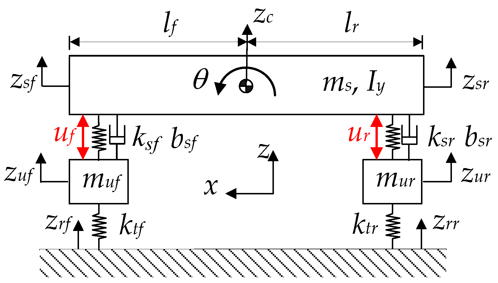
2.1. Half-Car Model for Controller Design

Generally, a half-car vehicle model is selected in order to describe the heave and pitch motions of a sprung mass. Figure 3 shows the free-body diagram of a half-car model. In Figure 3, the subscripts f and r represent the front and rear sides of the sprung mass, respectively. uf and ur are the active suspension forces generated by actuators at the front and rear suspensions. The forces acting on the front and rear suspensions are calculated as Equation (1). Using Equation (1), the equations of motions of the sprung and unsprung masses are given as Equation (2). Using the approximation, sinθθ, the vertical displacements at the front and rear corners of the sprung mass are calculated as Equation (3). From Equations (1)–(3), the state–space equation for the half-car model is derived using the procedure presented in previous studies [14,20,21].
f i = k s i z s i z u i b s i z ˙ s i z ˙ u i + u i , i = f , r
m s z ¨ c = f f + f r I y θ ¨ = l f f f + l r f f m u f z ¨ u f = f f k t f ( z u f z r f ) m u r z ¨ u r = f r k t r ( z u r z r r )
z s f = z c l f sin θ z c l f θ z s r = z c + l r sin θ z c + l r θ
New vectors are defined as Equation (4). In Equation (4), diag() represents the diagonal matrix with the elements in the parenthesis. With those definitions, the vector–matrix forms of the suspension forces, the equations of motions, and vertical displacements at both corners are obtained as Equations (5)–(7), respectively. By combining these equations, Equation (8) is derived. The vector–matrix form of Equation (8) is obtained as Equation (9). With those definitions on the matrices in Equation (9), the equations of motions in Equation (2) are converted into Equation (10).
p z c θ , z s z s f z s r , z u z u f z u r , w = z r z r f z r u , z p z u , x z z ˙ f f f f r , u u f u r , G 1 1 l f l r M s diag m s , I y , M u diag m u f , m u r K s diag k s f , k s r , B s diag b s f , b s r , K t diag k t f , k t r
f = K s z s z u B s z ˙ s z ˙ u + u
M s p ¨ = G f M u z ¨ u = f K t z u z r
z s = G T p
M s p ¨ = G K s G T p z u G B s G T p ˙ z ˙ u + G u M u z ¨ u = K s G T p z u + B s G T p ˙ z ˙ u u K t z u z r
M s 0 2 × 2 0 2 × 2 M u M p ¨ z ¨ u = G K s G T G K s K s G T K s K t K p z u + G B s G T G B s B s G T B s B p ˙ z ˙ u + G I 2 × 2 U u + 0 2 × 2 K t L z r
M z ¨ = K z ˙ + B z + U u + L w
New vectors z and x are defined in Equation (4). From Equations (10) and (4), the state–space equation of the half-car model is obtained as Equation (11) [14]. In Equation (11), the matrices A, B1 and B2 are defined as Equation (12).
x ˙ = A x + B 1 w + B 2 u
A 0 4 × 4 I 4 × 4 M 1 K M 1 B , B 1 0 4 × 2 M 1 L , B 2 0 4 × 2 M 1 U

2.2. Design of Linear Quadratic Regulator

LQ objective function with the half-car model is given as Equation (13). In Equation (13), the weights are set by Bryson’s rule, as given in Equation (14), where ξ is the maximum allowable value on the corresponding term [22]. For ride comfort enhancement, the weight ρ1 on the vertical acceleration should be set high. For motion sickness mitigation, the weights ρ1 and ρ3 on the heave acceleration and the pitch rate should be set high. The LQ objective function (13) is converted into a vector–matrix form, Equation (16). With the matrices A, B2, Q, N and R, LQR is easily designed as (16), where P is the solution of the Riccati equation.
J = 0 ρ 1 z ¨ c 2 + ρ 2 θ ¨ 2 + ρ 3 θ ˙ 2 + ρ 4 θ 2 + ρ 5 z s f z u f 2 + ρ 5 z s r z u r 2 + ρ 6 z u f z r f 2 + ρ 6 z u r z r r 2 + ρ 7 u f 2 + ρ 7 u r 2 d t
ρ i = 1 ξ i 2 , i = 1 , 2 , , 7
J = 0 x u T Q N N T R x u d t
u = K L Q R x = R 1 B 2 T P x

2.3. Design of Linear Quadratic Static Output Feedback Controller

Generally, in a real vehicle, it is hard to measure the state variables in x. For this reason, SOF control has been adopted instead of the full-state feedback. An SOF controller uses signals available in a real vehicle. In this paper, it is assumed that the heave velocity and the pitch rate of the sprung mass, and the suspension stroke rates of front and rear suspensions are available for SOF control.
To obtain these signals, two accelerometers should be installed on the front and rear corners of the sprung mass, and the other two sensors should be installed on the centers of front and rear wheels, as shown in Figure 4 [23,24]. These accelerometer signals are sequentially filtered by a low-pass filter (LPF) and high-pass filter (HPF) in order to reject noise and DC blocking, respectively. Then, those filtered signals are integrated by an integrator. The heave velocity and pitch rate are obtained from two vertical velocities of front and rear corners of the sprung mass with Equation (7).
The vector of four available outputs is defined from the state vector x as Equation (17). The control input of the SOF controller is obtained by Equation (18). As shown in Equation (18), there are three types of SOF controller, KSOF, KSSOF and KTSOF, where the second is called structured SOF or SSOF and the third is called derivative SOF or DSOF. The structured SOF, KSSOF, reflects the fact that there is symmetry between front and rear suspensions in terms of the pitch rate of the sprung mass. The derivative controller, KDSOF, controller uses only the heave velocity and pitch rate, which are identical to a derivative controller in PID control. Generally, a controller with a smaller number of gain elements is preferred for its simplicity if it has a satisfactory control performance. Moreover, DSOF only requires heave velocity and the pitch rate signals, which means that it is not necessary to measure heave accelerations at front and rear wheel centers. For this reason, DSOF is preferred to SOF or SSOF.
y = z ˙ c θ ˙ z ˙ s f z ˙ u f z ˙ s r z ˙ u r = C x = 0 0 0 0 1 0 0 0 0 0 0 0 0 1 0 0 0 0 0 0 1 l f 1 0 0 0 0 0 1 l r 0 1 x
u = K S O F y = k 11 k 12 k 13 k 14 k 21 k 22 k 23 k 24 y u = K S S O F y = k 1 k 2 k 3 k 4 k 1 k 2 k 3 k 4 y u = K D S O F y = k 1 k 2 0 0 k 1 k 2 0 0 y
The controller gain matrices, KSOF, KSSOF and KDSOF, that minimize J are called LQSOF, LQSSOF, and LQDSOF controllers, respectively. Currently, there are no methods to analytically calculate the controller gain matrix KSOF or KSSOF or KDSOF that minimizes J. Moreover, there are no systematic methods for finding a stabilizing initial condition. To find KSOF or KSSOF or KDSOF, which minimizes J, the optimization problem is formulated as Equation (19), which is non-convex [14,15]. In Equation (19), Ks is either KSOF or KSSOF or KDSOF. To solve this problem, the heuristic optimization method, CMA-ES, is adopted in this paper [19].
min K S trace P s s . t . P s = P s T > 0 max Re A + B 2 K S C < 0 A + B 2 K S C T P s + P s A + B 2 K S C + Q + C T K S T N T + N K S C + C T K S T R K S C = 0

2.4. Design of Static Output Feedback Controller with Simulation-Based Optimization

LQR, LQSOF, and LQSSOF controllers can be designed with the state–space equation derived from the linear system. Generally, a spring and a damper are nonlinear in a real vehicle. If a spring and a damper in the half-car model are nonlinear, LQR, LQSOF, and LQSSOF controllers cannot be designed with LQOC. To design SOF, SSOF, and DSOF controllers for a nonlinear model, a simulation-based optimization (SBOM) is adopted in this paper [16,17,18].
For this simulation-based optimization, a Simulink model is built from the equations of motions, Equation (2), and the controllers, Equation (18). With SBOM, it is necessary to find eight elements in KSOF or four elements in KSSOF or two elements in KDSOF that provide the minimum of an objective function. The objectives of the SBOM for ride comfort enhancement and motion sickness mitigation are calculated using the heave acceleration and pitch rate of the sprung mass. The objective function of the SBOM is calculated as Equation (20) by combining the values obtained from the simulation over the simulation horizon. In Equation (20), R2D is the constant from radian to degree, and α is a tuning parameter. In this paper, α is set to 0.1. For a particular gain matrix, KSOF or KSSOF or KDSOF, a simulation is conducted using the Simulink model. From the simulation results, a particular objective value of JSO is calculated. For optimization, heuristic optimization methods such as CMA-ES and fminsearch(), the built-in function in MATLAB, can be used. In this paper, CMA-ES is selected as an optimization method [19]. When applying CMA-Es, each element in the gain matrices is bounded between −100,000 and 100,000. The overall procedure of the SBOM is given in Figure 5.
J S O = max z ¨ c t + α · R 2 D · max θ ˙ t , t t 0 , t f
For the SBOM, a road profile should be selected. There are two typical road profiles used to evaluate a suspension control system: a single sine bump and a sine wave road. The single sine bump used for simulation has a height of 0.1m and width of 3.6 m, which is the Korean standard. Let this road profile be called SSB. The sine wave road has a wavelength of 12.2 m and amplitude of 0.05 m. Let this road profile be called SWR. These two road profiles are enough to excite the heave and pitch motions of the sprung mass within the range of 0.8~8 Hz. When using SWR for the SBOM, the vehicle speed is set to 20 m/s for the purpose of causing severe conditions. On the contrary, when using SSB, the vehicle speed is set to 10 m/s.
In simulation-based optimization, there are three controller structures, SOF, SSOF and DSOF, and two road profiles, SSB and SWR. Under these conditions, SOF, SSOF, and DSOF controllers can be designed on SSB and SWR. For this reason, six controllers are obtained from the combinations of (SOF, SSOF, DSOF) × (SSB, SWR). Let those controllers be called SOF.SSB, SSOF.SSB, DSOF.SSB, SOF.SWR, SSOF.SWR and DSOF.SWR, respectively. There are ten controllers in total, including LQR, LQSOF, LQSSOF, and LQDSOF.

3. Simulation

In this section, nine controllers except LQR are simulated in a co-simulation environment of MATLAB/Simulink and CarSim [25]. LQR is hard to simulate in CarSim because the state variables are not easy to obtain. Those controllers are compared in terms of the heave acceleration and pitch rate of the sprung mass for ride comfort enhancement and motion sickness mitigation.

3.1. Simulation Environment

The parameters of the half-car model are derived from the E-Class sedan model given in CarSim [25]. Table 1 shows the parameters of the half-car model. The weights in the LQ objective function are given in Table 2. As shown in Table 2, the weights on the heave acceleration and pitch rate are set high for ride comfort enhancement and motion sickness mitigation. Using the data given in Table 1 and Table 2, LQR, LQSOF, LQSOF and LQDSOF controllers are designed with LQOC.
In the Simulink model built for the SBOM, nonlinear spring and damper data are given in Figure 6. These data are also derived from the E-Class sedan model given in CarSim. In the simulation, it was assumed that there are no limits on suspension travel distance.

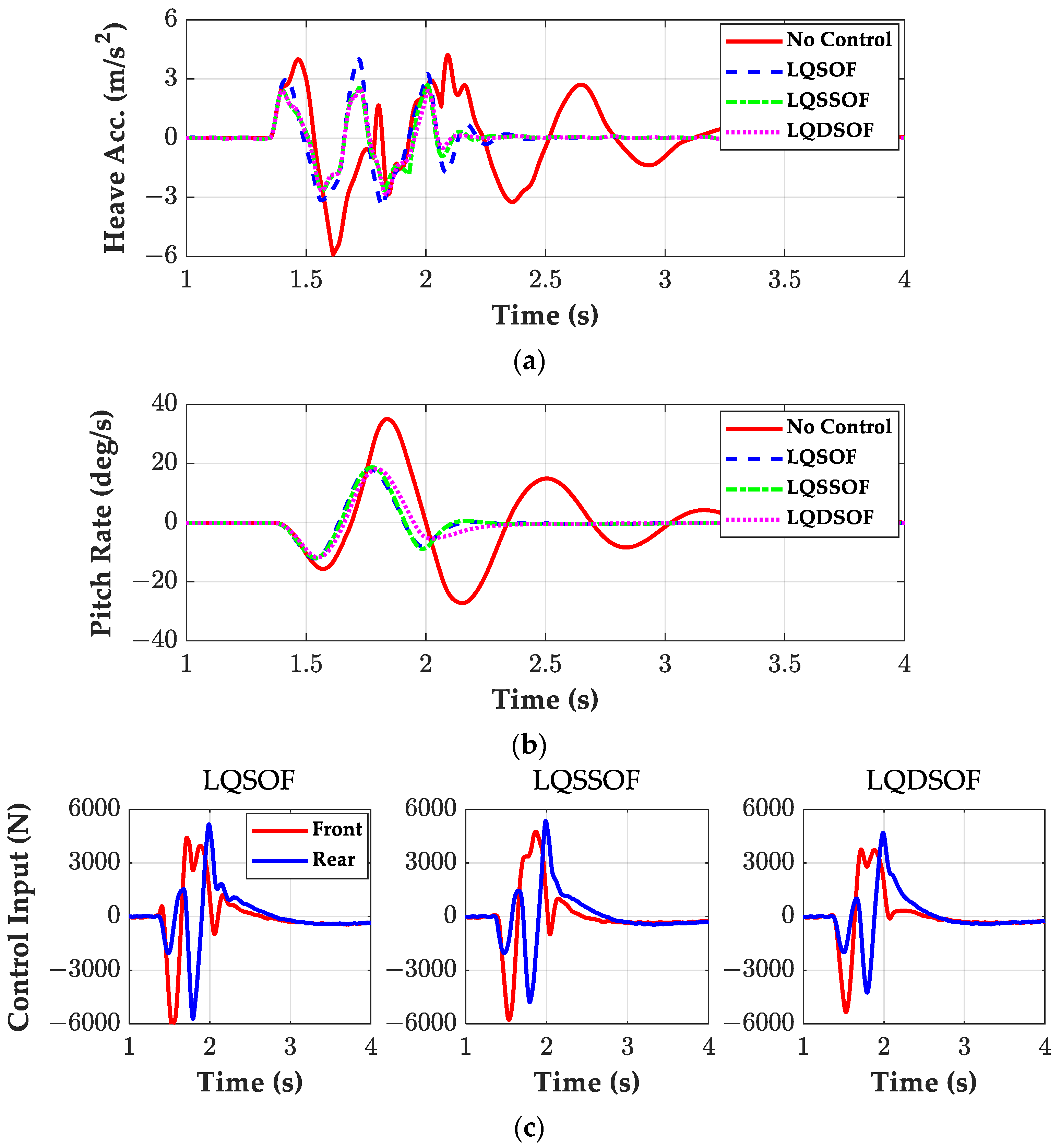
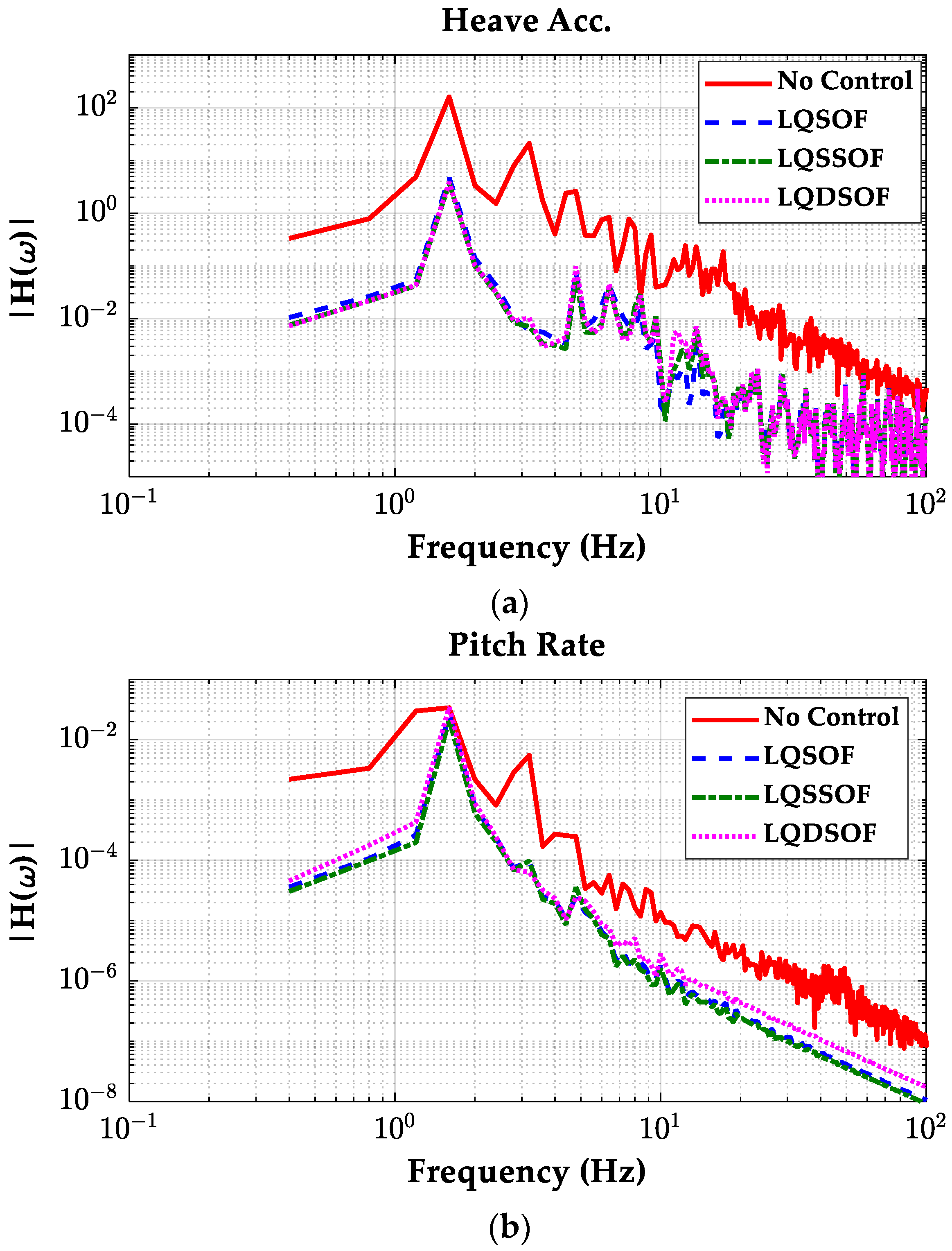
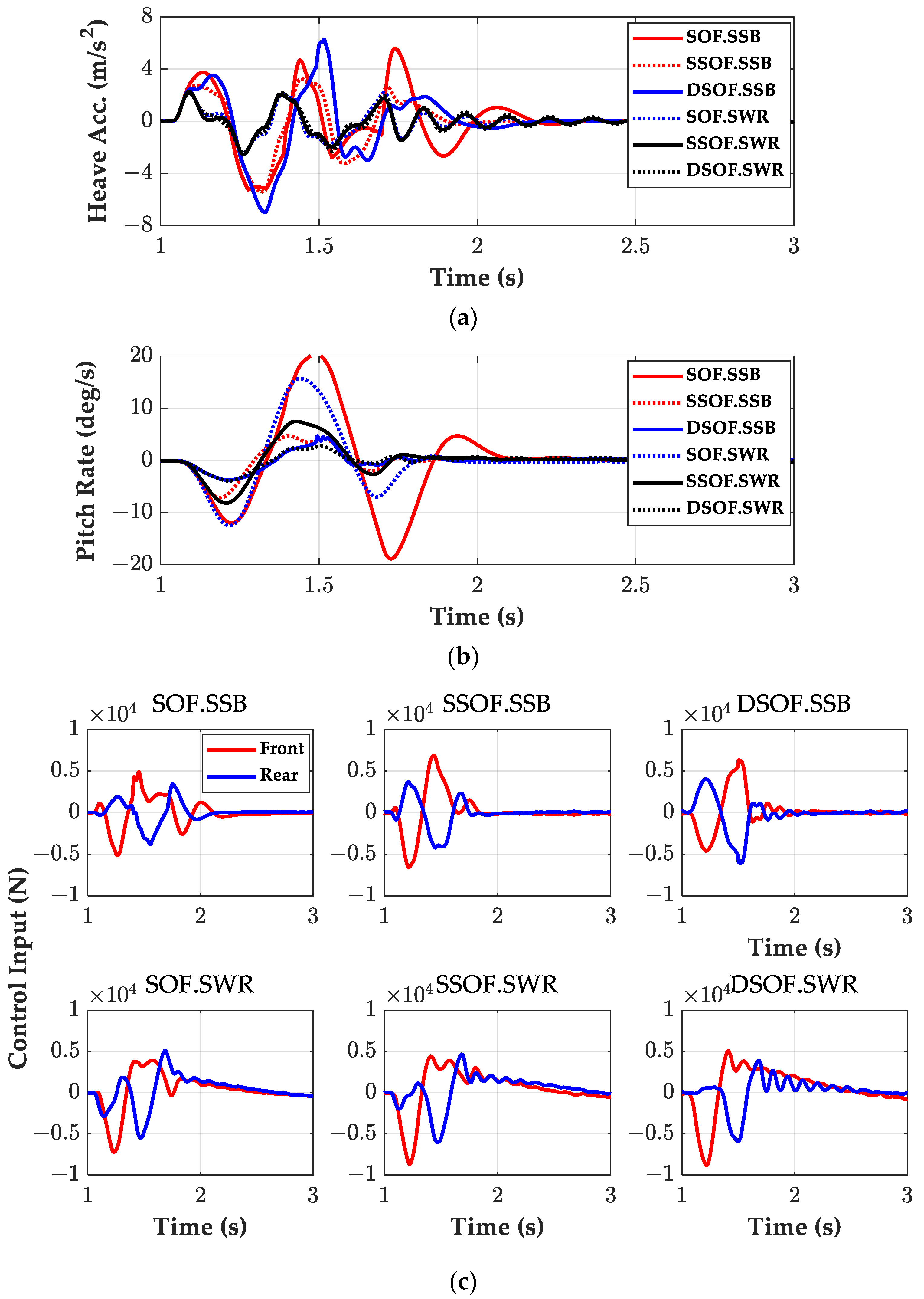
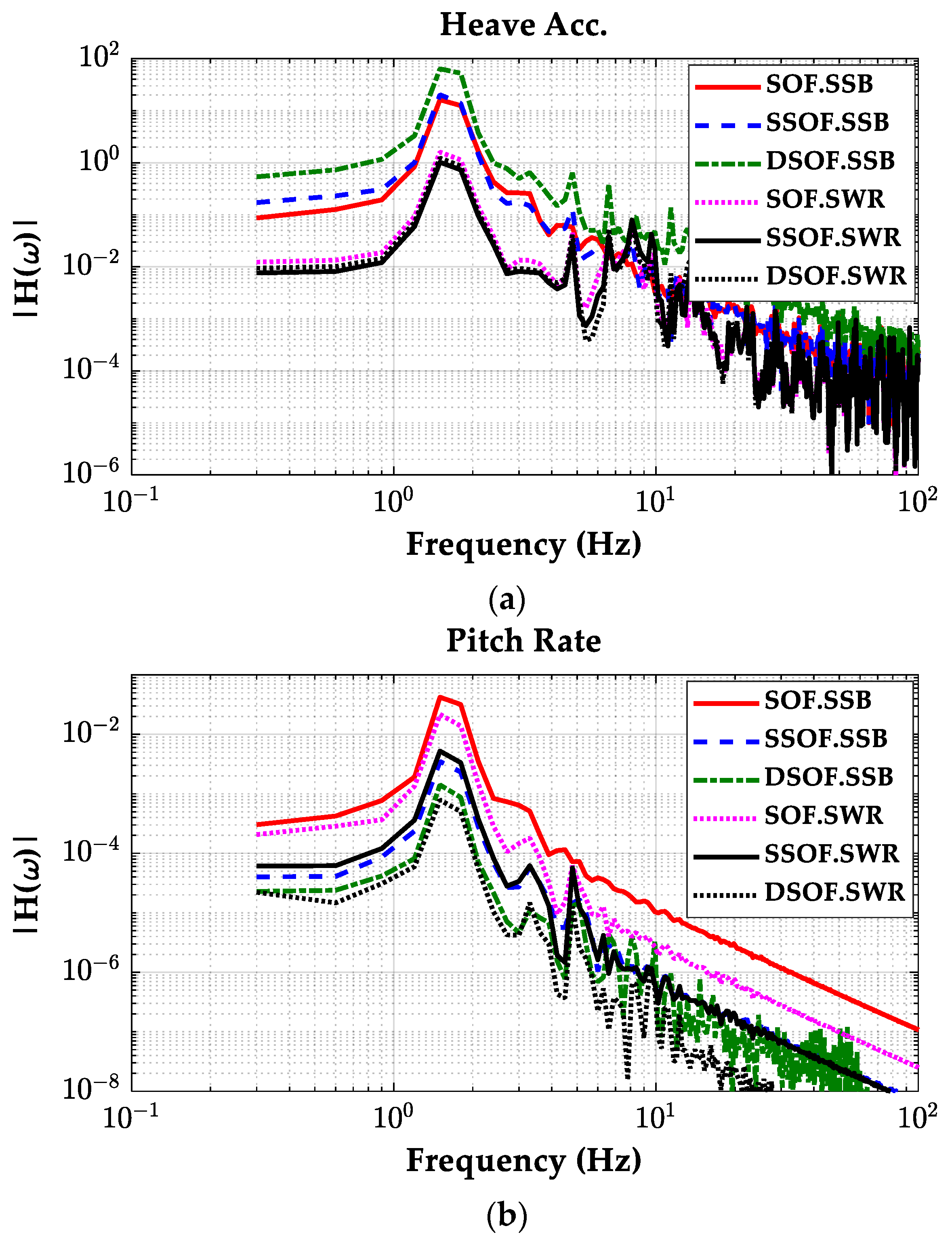
3.2. Comparison of Controllers on CarSim

In a CarSim simulation environment, the E-class sedan, built-in in CarSim, was selected as a vehicle model. In the simulation, two sets of controllers are simulated and compared. The first set consists of LQR, LQSOF, and LQSSOF. The second set consists of SOF.SSB, SSOF.SSB, DSOF.SSB, SOF.SWR, SSOF.SWR and DSOF.SWR. All controllers are implemented in MATLAB/Simulink, connected with CarSim. The single sine bump and the sine wave road are selected as a road profile for simulation. The actuator was modeled as a first-order system with a bandwidth of 20 Hz, and it has no limitations of force. When carrying out a simulation on SSB and SWR, vehicle speeds are set to 10 m/s and 20 m/s, respectively. The filtered and integrated signals obtained in Figure 4 are used as outputs in y for the SOF controllers.
Figure 7 and Figure 8 show the simulation results for the LQSOF, LQSSOF, and LQDSOF controllers on two road profiles. Figure 9 and Figure 10 show the frequency responses of those controllers obtained from the simulation results in SSB and SWR. Table 3 summarizes these simulation results.
As shown in Figure 7 and Figure 8, the three controllers show good performance in terms of the heave acceleration of the sprung mass. This is achieved by setting the weight ρ1 very high. A notable feature is that these controllers show identical performance to one another in view of the heave acceleration and pitch rate of the sprung mass on SSB and SWR. Another feature is that these controllers have relatively poor performance in controlling the pitch rate. If one wants to reduce the pitch rate, then the weight ρ4 should be set higher. However, as a result, the heave acceleration will increase. This is a well-known tradeoff among the terms in the LQ objective function. As shown in Figure 7c, the control inputs converge slowly to zero because the controllers are just derivative and do not use displacement signals. To remove this phenomenon, an integral control can be included in those controllers.
The frequency responses given in Figure 9 and Figure 10 means that three controllers can effectively attenuate the effect of the road profile on the heave acceleration and the pitch rate of the sprung mass below 3 Hz. This value can be increased if an actuator with higher bandwidth is used. Moreover, on both road profiles, there are slight differences among those controllers. As shown in Figure 10b, the pitch rate was not reduced close to 2 Hz.
As shown in Equation (18), LQDSOF has only two gain elements, the simplest form among the three controllers. This is quite desirable when implementing the controller on a real vehicle. Moreover, it is easier to apply the SBOM to find the optimum gain of the LQDSOF controller. As mentioned earlier, there are small differences between the three controllers in terms of performance. For this reason, LQDSOF is recommended as an active suspension controller for ride comfort enhancement and motion sickness mitigation.
Figure 11 and Figure 12 show the simulation results for six controllers, SOF.SSB, SSOF.SSB, DSOF.SSB, SOF.SWR, SSOF.SWR, and DSOF.SWR, on two road profiles. Figure 13 and Figure 14 show the frequency responses of those controllers obtained from the simulation results in SSB and SWR. Table 4 summarizes these simulation results.
As shown in Figure 11 and Figure 12, SOF.SWR, SSOF.SWR, and DSOF.SWR, designed using a simulation-based optimization on the sine wave road, have good performance for the corresponding road profile. On the contrary, SOF.SSB, SSOF.SSB, and DSOF.SSB have relatively poor performance in reducing the heave acceleration of the sprung mass. In terms of the pitch rate, SSOF and DSOF show good performance. Among them, DSOF.SWR is the best controller in terms of the heave acceleration and the pitch rate of the sprung mass on both road profiles. In particular, the pitch rate can be reduced to 10% of the passive case by DSOF.SWR. From these results, it can be concluded that SBOM is superior to LQOC for SOF controller design.
The frequency responses given in Figure 13 and Figure 14 show that those six controllers can reduce the effects of the road profiles on the heave acceleration and the pitch rate of the sprung mass below 4 Hz. This value can be also increased if an actuator with a higher bandwidth is used. Different from Figure 10b, the pitch rates were reduced by the controllers designed using SBOM over the entire frequency range. This is the main difference between the SOF controllers designed by LQOC and SBOM. For this reason, SBOM is preferred to LQOC.
The above results mean that DSOF.SWR requires only two signals, i.e., heave velocity and pitch rate, for ride comfort enhancement and motion sickness mitigation. Moreover, DSOF.SWR is a simple derivative controller, which increases damping along the heave and pitch motions.

4. Conclusions

This paper presents a method for designing an active suspension controller for ride comfort enhancement and motion sickness mitigation. Three types of controller structure were proposed and designed for SOF control using a linear quadratic optimal control and simulation-based optimization method. In simulation-based optimization, a single sine bump and a sine wave road were used as road profiles. Six controllers, the combinations of three SOF controllers and two road profiles, were designed and simulated using CarSim. For SOF controllers, this paper presented a method for deriving the heave velocity, the pitch rate and the front/rear suspension velocity from four accelerometer signals. From the simulation results, it was shown that SBOM is superior to LQOC, and that the simplest controller, the DSOF controller, designed on the sine wave road with SBOM, showed the best performance in terms of ride comfort enhancement and motion sickness mitigation. This is meaningful in that only two signals, the heave velocity and the pitch rate of the sprung mass, are needed for the DSOF controller and that it is easy to implement the DSOF controller on a real vehicle. Moreover, in experiments on real vehicles, the controller gain of DSOF.SWR, obtained using SBOM, can be used as a starting point, which can significantly reduce efforts to tune the gain. In further research, a semi-active actuator such as continuous damping control and a magnetorheological damper can be used for suspension control.

Author Contributions

Conceptualization, Y.J. and S.Y.; methodology, S.Y.; software, Y.J.; validation, Y.J. and S.Y.; formal analysis, S.Y.; investigation, Y.J. and S.Y.; resources, S.Y.; data curation, S.Y.; writing—original draft preparation, S.Y.; writing—review and editing, Y.J.; visualization, S.Y.; supervision, S.Y.; funding acquisition, S.Y. All authors have read and agreed to the published version of the manuscript.

Funding

This work was supported by the Ministry of Education through the National Research Foundation of Korea (NRF) under Basic Science Research Program (NRF-2019R1A6A1A03032119).

Data Availability Statement

The original contributions presented in the study are included in the article, further inquiries can be directed to the corresponding author.

Conflicts of Interest

The authors declare no conflicts of interest.

Nomenclature

DSOFderivative static output feedback control
LQOClinear quadratic optimal control
LQRlinear quadratic regulator
LQSOFlinear quadratic static output feedback
LQSSOFlinear quadratic structured static output feedback
LQDSOFlinear quadratic derivative static output feedback
SBOMsimulation-based optimization method
SOFstatic output feedback
SSOFstructured static output feedback
SSBsingle sine bump
SWRsine wave road
Iypitch moment of inertial (kg⋅m2)
bsf, bsrdamping coefficient of dampers at front and rear suspensions (N⋅s/m)
ksf, ksrspring stiffness of springs at front and rear suspensions (N/m)
ktf, ktrspring stiffness of front and rear tires (N/m)
lf, lrdistances from center of gravity of a sprung mass to front and rear axles (m)
mssprung mass (kg)
muf, murunsprung masses (kg)
uf, urforces generated by front and rear active suspensions (N)
zcheave displacement at center of gravity of a sprung mass (m)
zrf, zrrroad elevations of front and rear tire-road contact positions (m)
zsf, zsrvertical displacements of front and rear corners of a sprung mass (m)
zuf, zurvertical displacements of front and rear wheel centers (m)
ξimaximum allowable value of weight in LQ objective function
ρiweight in LQ objective function
θpitch angle of a sprung mass (rad)

References

  1. Tseng, H.E.; Hrovat, D. State of the art survey: Active and semi-active suspension control. Veh. Syst. Dyn. 2015, 53, 1034–1062. [Google Scholar] [CrossRef]
  2. ISO 2631-1; Mechanical Vibration and Shock—Evaluation of Human Exposure to Whole-Body Vibration—Part 1: General Requirements. International Organization for Standardization: Geneva, Switzerland, 1997.
  3. Rimell, A.N.; Mansfield, N.J. Design of digital filters for frequency weightings required for risk assessments of workers exposed to vibration. Ind. Health 2007, 45, 512–519. [Google Scholar] [CrossRef] [PubMed]
  4. Yurtsever, E.; Lambert, J.; Carballo, A.; Takeda, K. A survey of autonomous driving: Common practices and emerging tech-nologies. IEEE Access 2020, 8, 58443–58469. [Google Scholar] [CrossRef]
  5. Diels, C.; Bos, J.E. Self-driving carsickness. Appl. Ergon. 2016, 53, 374–382. [Google Scholar] [CrossRef] [PubMed]
  6. Cheung, B.; Nakashima, A. A Review on the Effects of Frequency of Oscillation on Motion Sickness; Technical Report, TR 2006-229; Defence R&D Canada: Toronto, ON, Canada, 2006. [Google Scholar]
  7. McCauley, M.E.; Royal, J.W.; Wylie, C.D.; O’Hanlon, J.F.; Mackie, R.R. Motion Sickness Incidence: Exploratory Studies of Habituation, Pitch and Roll and the Refinement of a Mathematical Model; Technical Report 1733-2; Human Factors Research Inc.: Goleta, CA, USA, 1976. [Google Scholar]
  8. Ekchian, J.; Graves, W.; Anderson, Z.; Giovanardi, M.; Godwin, O.; Kaplan, J.; Ventura, J.; Lackner, J.R.; DiZio, P. A High-Bandwidth Active Suspension for Motion Sickness Mitigation in Autonomous Vehicles; SAE Technical Paper 2016-01-1555; SAE International: Warrendale, PA, USA, 2016. [Google Scholar]
  9. DiZio, P.; Ekchian, J.; Kaplan, J.; Ventura, J.; Graves, W.; Giovanardi, M.; Anderson, Z.; Lackner, J.R. An active suspension system for mitigating motion sickness and enabling reading in a car. Aerosp. Med. Hum. Perform. 2018, 89, 822–829. [Google Scholar] [CrossRef]
  10. Jurisch, M.; Holzapfel, C.; Buck, C. The influence of active suspension systems on motion sickness of vehicle occupants. In Proceedings of the IEEE 23rd International Conference on Intelligent Transportation Systems (ITSC), Rhodes, Greece, 20–23 September 2020. [Google Scholar]
  11. Hrovat, D. Survey of advanced suspension developments and related optimal control applications. Automatica 1997, 33, 1781–1817. [Google Scholar] [CrossRef]
  12. Cao, D.; Song, X.; Ahmadian, M. Editors’ perspectives: Road vehicle suspension design, dynamics, and control. Veh. Syst. Dyn. 2011, 49, 3–28. [Google Scholar] [CrossRef]
  13. Al-Ashmori, M.; Wang, X.A. Systematic literature review of various control techniques for active seat suspension systems. Appl. Sci. 2020, 10, 1148. [Google Scholar] [CrossRef]
  14. Park, M.; Yim, S. Design of static output feedback and structured controllers for active suspension with quarter-car model. Energies 2021, 14, 8231. [Google Scholar] [CrossRef]
  15. Jeong, Y.; Shon, Y.; Chang, S.; Yim, S. Design of static output feedback controllers for an active suspension system. IEEE Access 2022, 10, 26948–26964. [Google Scholar] [CrossRef]
  16. Yim, S.; Choi, J.; Yi, K. Coordinated control of hybrid 4WD vehicles for enhanced maneuverability and lateral stability. IEEE Trans. Veh. Technol. 2012, 61, 1946–1950. [Google Scholar] [CrossRef]
  17. Nah, J.; Yim, S. Optimization of control allocation with ESC, AFS, ARS and TVD in integrated chassis control. J. Mech. Sci. Technol. 2019, 33, 2941–2948. [Google Scholar] [CrossRef]
  18. Jeong, Y.; Shon, Y.; Chang, S.; Yim, S. Design of virtual reference feedforward controller for an active suspension system. IEEE Access. 2022, 10, 65671–65684. [Google Scholar] [CrossRef]
  19. Hansen, N.; Muller, S.D.; Koumoutsakos, P. Reducing the time complexity of the derandomized evolution strategy with covariance matrix adaptation (CMA-ES). Evol. Comput. 2003, 11, 1–18. [Google Scholar] [CrossRef] [PubMed]
  20. Lu, J.; DePoyster, M. Multiobjective optimal suspension control to achieve integrated ride and handling performance. IEEE Trans. Control Syst. Technol. 2002, 10, 807–821. [Google Scholar]
  21. Jung, Y.H.; Choi, J.W.; Seo, Y.B. Overlapping decentralized EA control design for an active suspension system of a full car model. In Proceedings of the 39th SICE Annual Conference, Iizuka, Japan, 28 July 2000; pp. 85–90. [Google Scholar]
  22. Bryson, A.E.; Ho, Y.C. Applied Optimal Control; Hemisphere: New York, NY, USA, 1975. [Google Scholar]
  23. Ding, R.; Wang, R.; Meng, X.; Chen, L. Energy consumption sensitivity analysis and energy-reduction control of hybrid electromagnetic active suspension. Mech. Syst. Signal Process. 2019, 134, 106301. [Google Scholar] [CrossRef]
  24. Liu, W.; Wang, R.; Ding, R.; Meng, X.; Yang, L. On-line estimation of road profile in semi-active suspension based on unsprung mass acceleration. Mech. Syst. Signal Process. 2020, 135, 106370. [Google Scholar] [CrossRef]
  25. Mechanical Simulation Corporation. CarSim Data Manual; Version 8; Mechanical Simulation Corporation: Ann Arbor, MA, USA, 2009. [Google Scholar]
Figure 1. Frequency weightings specified in the ISO 2631-1 standard [2].
Machines 12 00254 g001
Figure 2. Effects of frequency on motion sickness [6].
Machines 12 00254 g002
Figure 3. Half-car model.
Machines 12 00254 g003
Figure 4. Block diagram for velocity and angular rate calculation.
Machines 12 00254 g004
Figure 5. Block diagram of SBOM.
Machines 12 00254 g005
Figure 6. Spring and damper characteristics of the Simulink model for the half-car model.
Machines 12 00254 g006
Figure 7. Simulation results of LQSOF, LQSSOF, and LQDSOF for a single sine bump. (a) Heave accelerations; (b) pitch rates; (c) control inputs.
Machines 12 00254 g007
Figure 8. Simulation results of LQSOF, LQSSOF, and LQDSOF on the sine wave road. (a) Heave accelerations; (b) pitch rates; (c) control inputs.
Machines 12 00254 g008
Figure 9. Frequency responses of LQSOF, LQSSOF, and LQDSOF on the single sine bump. (a) Heave accelerations; (b) pitch rates.
Machines 12 00254 g009aMachines 12 00254 g009b
Figure 10. Frequency responses of LQSOF, LQSSOF, and LQDSOF on the sine wave road. (a) Heave accelerations; (b) pitch rates.
Machines 12 00254 g010
Figure 11. Simulation results for six controllers on the single sine bump. (a) Heave accelerations; (b) pitch rates; (c) control inputs.
Machines 12 00254 g011
Figure 12. Simulation results for six controllers on the sine wave road. (a) Heave accelerations; (b) pitch rates; (c) control inputs.
Machines 12 00254 g012aMachines 12 00254 g012b
Figure 13. Frequency responses of six controllers on the single sine bump. (a) Heave accelerations; (b) pitch rates.
Machines 12 00254 g013aMachines 12 00254 g013b
Figure 14. Frequency responses for six controllers on the sine wave road. (a) Heave accelerations; (b) pitch rates.
Machines 12 00254 g014
Table 1. Parameters and values of the half-car model are derived from the E-class sedan model in CarSim.
ParameterValueParameterValue
ms1653 kgmu22.5 kg
Iy2765 kg⋅m2ktf, ktr230,000 N/m
lf0.8 mlr1.646 m
ksf, ksr34,000 N/mbsf, bsr3500 Ns/m
Table 2. Maximum allowable values of each term in LQ objective function.
WeightVariableValueWeightVariableValue
ξ1Heave acc.0.1 m/s2ξ2Pitch angular acc.30 deg/s2
ξ3Pitch rate2 deg/sξ4Pitch angle2 deg
ξ5Suspension stroke0.03 mξ6Tire deflection0.03 m
ξ7Control input5000 N
Table 3. Summary of the simulation results with LQSOF, LQSSOF, and LQDSOF.
Road ProfileController Max   z ¨ c
(m/s2)
Max   θ ˙
(deg/s)
Max Front Force
(N)
Max Rear Force
(N)
Single sine bumpNo Control5.935.0
LQSOF4.018.060455720
LQSSOF2.718.757775347
LQDSOF2.918.153424679
Sine wave roadNo Control25.528.6
LQSOF3.19.354483343
LQSSOF2.98.357453432
LQDSOF3.010.853933664
Table 4. Summary of the simulation results on the single sine bump.
Road ProfileController Max   z ¨ c
(m/s2)
Max   θ ˙
(deg/s)
Max Front Force
(N)
Max Rear Force
(N)
Single sine bumpNo Control5.935.0
SOF.SSB5.620.451393800
SSOF.SSB5.47.168824206
DSOF.SSB7.04.763196083
SOF.SWR2.515.772245499
SSOF.SWR2.58.286706042
DSOF.SWR2.43.988495904
Sine wave roadNo Control25.528.6
SOF.SSB6.214.260652000
SSOF.SSB5.54.149912173
DSOF.SSB10.23.249433465
SOF.SWR2.49.559603685
SSOF.SWR2.44.761034139
DSOF.SWR2.42.165744090
Disclaimer/Publisher’s Note: The statements, opinions and data contained in all publications are solely those of the individual author(s) and contributor(s) and not of MDPI and/or the editor(s). MDPI and/or the editor(s) disclaim responsibility for any injury to people or property resulting from any ideas, methods, instructions or products referred to in the content.

