


A Concise Review on Materials for Injection Moulds and Their Conventional and Non-Conventional Machining Processes

 , ,
, ,  ,
,  ,
,  ,
, 
 and
and
Abstract
:1. Introduction
1.1. Copper–Beryllium Alloys (AMPCO®)
1.2. Iron–Nickel (INVAR-36®)
1.3. HT Steels
2. Materials and Methods
3. Literature Review
3.1. Conventional Manufacturing (CM)
3.1.1. Milling
3.1.2. Turning
3.1.3. Drilling
3.1.4. Surface Polishing
3.2. Non-Conventional Manufacturing (NCM)
3.2.1. Electrical Discharge Machining (EDM)
3.2.2. Laser Beam Drilling (LBD)
4. Discussion
5. Conclusions
- Both AMPCO® and HT steels exhibit good machinability characteristics in milling and turning processes, allowing for an efficient MRR and dimensional accuracy,
- INVAR-36® presents challenges due to its low k and tendency to generate heat during machining, requiring the careful selection of cutting parameters to avoid TW and surface defects,
- The drillability of AMPCO® is generally favourable, with optimal cutting parameters leading to efficient hole production and minimal TW,
- INVAR-36® poses challenges in drilling due to its high plasticity and toughness, leading to increased thrust forces and Tcut,
- The surface polishing of AMPCO® and INVAR-36® can be effectively achieved using techniques such as electropolishing and nano-polishing, enhancing surface quality and corrosion resistance,
- HT steels may require additional post-machining processes to achieve the desired surface finishes, depending on the specific material characteristics and machining parameters,
- EDM proves to be a versatile machining technique for all three addressed alloys, offering high precision and complex shape capabilities,
- Challenges include the formation of surface defects and recast layers, particularly in HT steels, requiring careful process optimization and control,
- LBD demonstrates high efficiency and precision in drilling micro-holes in materials like INVAR-36®, with techniques such as burst mode and ultrashort pulsed lasers yielding promising results,
- The optimization of laser parameters is crucial for achieving the desired drilling quality while minimizing heat-affected zones and surface defects.
Author Contributions
Funding
Data Availability Statement
Acknowledgments
Conflicts of Interest
References
- Silva, F.J.G.; Martinho, R.P.; Alexandre, R.J.D.; Baptista, A.P.M. Increasing the wear resistance of molds for injection of glass fiber reinforced plastics. Wear 2011, 271, 2494–2499. [Google Scholar] [CrossRef]
- Martinho, R.P.; Silva, F.J.; Alexandre, R.J.; Baptista, A.P. TiB2 nanostructured coating for GFRP injection moulds. J. Nanosci. Nanotechnol. 2011, 11, 5374–5382. [Google Scholar] [CrossRef] [PubMed]
- Arruda, É.M.; de Paiva, A.P.; Brandão, L.C.; Ferreira, J.R. Robust optimisation of surface roughness of AISI H13 hardened steel in the finishing milling using ball nose end mills. Precis. Eng. 2019, 60, 194–214. [Google Scholar] [CrossRef]
- Park, S.J.; Lee, J.H.; Yang, J.; Heogh, W.; Kang, D.; Yeon, S.M.; Kim, S.H.; Hong, S.; Son, Y.; Park, J. Lightweight injection mold using additively manufactured Ti-6Al-4V lattice structures. J. Manuf. Process. 2022, 79, 759–766. [Google Scholar] [CrossRef]
- Silva, F.J.G.; Martinho, R.P.; Baptista, A.P.M. Characterization of laboratory and industrial CrN/CrCN/diamond-like carbon coatings. Thin Solid Film. 2014, 550, 278–284. [Google Scholar] [CrossRef]
- Nunes, V.; Silva, F.J.G.; Andrade, M.F.; Alexandre, R.; Baptista, A.P.M. Increasing the lifespan of high-pressure die cast molds subjected to severe wear. Surf. Coat. Technol. 2017, 332, 319–331. [Google Scholar] [CrossRef]
- Pinto, H.; Silva, F.J.G. Optimisation of Die Casting Process in Zamak Alloys. Procedia Manuf. 2017, 11, 517–525. [Google Scholar] [CrossRef]
- Pinto, H.A.; Silva, F.J.G.; Martinho, R.P.; Campilho, R.D.S.G.; Pinto, A.G. Improvement and validation of Zamak die casting moulds. Procedia Manuf. 2019, 38, 1547–1557. [Google Scholar] [CrossRef]
- Almeida, F.d.; Sousa, V.F.C.; Silva, F.J.G.; Campilho, R.D.S.G.; Ferreira, L.P. Development of a Novel Design Strategy for Moving Mechanisms Used in Multi-Material Plastic Injection Molds. Appl. Sci. 2021, 11, 11805. [Google Scholar] [CrossRef]
- Penne, R.; Silva, F.; Campilho, R.; Santos, G.; Sousa, V.; Ferreira, L.; Sá, J.; Pereira, M. A new approach to increase the environmental sustainability of the discharging process in the over-injection of conduits for bowden cables using automation. Proc. Inst. Mech. Eng. Part C J. Mech. Eng. Sci. 2022, 236, 8823–8833. [Google Scholar] [CrossRef]
- Ellingsen, D.G.; Møller, L.B.; Aaseth, J. Chapter 35—Copper. In Handbook on the Toxicology of Metals, 4th ed.; Nordberg, G.F., Fowler, B.A., Nordberg, M., Eds.; Academic Press: San Diego, CA, USA, 2015; pp. 765–786. [Google Scholar]
- Freudenberger, J.; Tikana, L.; Hosford, W.F. Alloys: Copper. In Encyclopedia of Condensed Matter Physics, 2nd ed.; Chakraborty, T., Ed.; Academic Press: Oxford, UK, 2024; pp. 601–634. [Google Scholar]
- ASM International. Surface Engineering; ASM International: West Conshohocken, PA, USA, 1994. [Google Scholar]
- Sousa, V.F.C.; Castanheira, J.; Silva, F.J.G.; Fecheira, J.S.; Pinto, G.; Baptista, A. Wear Behavior of Uncoated and Coated Tools in Milling Operations of AMPCO (Cu-Be) Alloy. Appl. Sci. 2021, 11, 7762. [Google Scholar] [CrossRef]
- Jacquet, P.A. Electrolytic Method for obtaining Bright Copper Surfaces. Nature 1935, 135, 1076. [Google Scholar] [CrossRef]
- Hoar, T.P.; Rothwell, G.P. The influence of solution flow on anodic polishing. Copper in aqueous o-phosphoric acid. Electrochim. Acta 1964, 9, 135–150. [Google Scholar] [CrossRef]
- Jakubowski, M.; PałczyŃski, C. Chapter 30—Beryllium. In Handbook on the Toxicology of Metals, 4th ed.; Nordberg, G.F., Fowler, B.A., Nordberg, M., Eds.; Academic Press: San Diego, CA, USA, 2015; pp. 635–653. [Google Scholar]
- Zou, Y.; Chen, G.; Ren, C.; Ge, J.; Qin, X. Performance and mechanism of hole-making of CFRP/Ti-6Al-4V stacks using ultrasonic vibration helical milling process. Int. J. Adv. Manuf. Technol. 2021, 117, 3529–3547. [Google Scholar] [CrossRef]
- Wang, Z.; Kovvuri, V.R.; Araujo, A.C.; Bacci Da Silva, M.; Hung, N.; Bukkapatnam, S. Built-up-edge effects on surface deterioration in micromilling processes. J. Manuf. Process. 2016, 24, 321–327. [Google Scholar] [CrossRef]
- Zitoune, R.; Krishnaraj, V.; Sofiane Almabouacif, B.; Collombet, F.; Sima, M.; Jolin, A. Influence of machining parameters and new nano-coated tool on drilling performance of CFRP/Aluminium sandwich. Compos. Part B Eng. 2012, 43, 1480–1488. [Google Scholar] [CrossRef]
- Ozcatalbas, Y. Chip and built-up edge formation in the machining of in situ Al4C3–Al composite. Mater. Des. 2003, 24, 215–221. [Google Scholar] [CrossRef]
- Campbell, F.C. Chapter 3—Magnesium and Beryllium. In Manufacturing Technology for Aerospace Structural Materials; Campbell, F.C., Ed.; Elsevier Science: Oxford, UK, 2006; pp. 93–118. [Google Scholar]
- Crone, W.C. Compositional variation and precipitate structures of copper–beryllium single crystals grown by the Bridgman technique. J. Cryst. Growth 2000, 218, 381–389. [Google Scholar] [CrossRef]
- Prashanth Reddy, K.; Panitapu, B. High thermal conductivity mould insert materials for cooling time reduction in thermoplastic injection moulds. Mater. Today Proc. 2017, 4, 519–526. [Google Scholar] [CrossRef]
- Zhong, Z.W.; Leong, M.H.; Liu, X.D. The wear rates and performance of three mold insert materials. Mater. Des. 2011, 32, 643–648. [Google Scholar] [CrossRef]
- ASTM B 194-15; Standard Specification for Copper-Beryllium Alloy Plate, Sheet, Strip, and Rolled Bar. ASTM International: West Conshohocken, PA, USA, 2015.
- Tan, C.; Zhou, K.; Ma, W.; Min, L. Interfacial characteristic and mechanical performance of maraging steel-copper functional bimetal produced by selective laser melting based hybrid manufacture. Mater. Des. 2018, 155, 77–85. [Google Scholar] [CrossRef]
- Cunha, A.; Marques, A.; Silva, F.S.; Gasik, M.; Trindade, B.; Carvalho, O.; Bartolomeu, F. 420 stainless steel-Cu parts fabricated using 3D Multi-Material Laser Powder Bed Fusion: A new solution for plastic injection moulds. Mater. Today Commun. 2022, 32, 103852. [Google Scholar] [CrossRef]
- Huzaim, N.H.M.; Rahim, S.Z.A.; Musa, L.; Abdellah, A.E.-h.; Abdullah, M.M.A.B.; Rennie, A.; Rahman, R.; Garus, S.; Błoch, K.; Sandu, A.V.; et al. Potential of Rapid Tooling in Rapid Heat Cycle Molding: A Review. Materials 2022, 15, 3725. [Google Scholar] [CrossRef]
- Baragetti, S.; Terranova, A.; Vimercati, M. Friction behaviour evaluation in beryllium–copper threaded connections. Int. J. Mech. Sci. 2009, 51, 790–796. [Google Scholar] [CrossRef]
- Sharma, A.; Joshi, S.S.; Datta, D.; Balasubramaniam, R. Modeling and analysis of tool wear mechanisms in diamond turning of copper beryllium alloy. J. Manuf. Process. 2020, 56, 439–450. [Google Scholar] [CrossRef]
- Ramesh, B.; Venkatesh, R.; Abraham, D.; Clement, S.; Ronadson, B.; Elayaperumal, A. Optimization of Process Parameter Levels during Conventional Milling of Beryllium Copper Alloy Using End Mill. Int. J. Adv. Res. Sci. Eng. 2013, 1, 57–63. [Google Scholar]
- Avelar-Batista Wilson, J.C.; Banfield, S.; Eichler, J.; Leyland, A.; Matthews, A.; Housden, J. An investigation into the tribological performance of Physical Vapour Deposition (PVD) coatings on high thermal conductivity Cu-alloy substrates and the effect of an intermediate electroless Ni–P layer prior to PVD treatment. Thin Solid Film. 2012, 520, 2922–2931. [Google Scholar] [CrossRef]
- Nogueira, F.R.; Pedroso, A.F.V.; Silva, F.J.G.; Campilho, R.D.S.G.; Sales-Contini, R.C.M.; Sebbe, N.P.V.; Casais, R.C.B. A Comparative Study on the Wear Mechanisms of Uncoated and TiAlTaN-Coated Tools Used in Machining AMPCO® Alloy. Coatings 2024, 14, 4. [Google Scholar] [CrossRef]
- Durocher, A.; Lipa, M.; Chappuis, P.; Schlosser, J.; Huber, T.; Schedler, B. TORE SUPRA experience of copper chromium zirconium electron beam welding. J. Nucl. Mater. 2002, 307–311, 1554–1557. [Google Scholar] [CrossRef]
- Lipa, M.; Durocher, A.; Tivey, R.; Huber, T.; Schedler, B.; Weigert, J. The use of copper alloy CuCrZr as a structural material for actively cooled plasma facing and in vessel components. Fusion Eng. Des. 2005, 75–79, 469–473. [Google Scholar] [CrossRef]
- Nogueira, F.R.; Pedroso, A.F.V.; Sousa, V.F.C.; Sebbe, N.P.V.; Sales-Contini, R.C.M.; Barbosa, M.L.S. A Brief Review of Injection-Mould Materials Hybrid Manufacturing Processes. In Intelligent Manufacturing: Establishing Bridges for More Sustainable Manufacturing Systems; Springer: Cham, Switzerland, 2024; pp. 796–806. [Google Scholar]
- Butterworth, G.J.; Forty, C.B.A. A survey of the properties of copper alloys for use as fusion reactor materials. J. Nucl. Mater. 1992, 189, 237–276. [Google Scholar] [CrossRef]
- Rouxel, B.; Mischler, S.; Logé, R.; Igual Munoz, A. Wear behaviour of novel copper alloy as an alternative to copper-beryllium. Wear 2023, 524, 204817. [Google Scholar] [CrossRef]
- Cacciamani, G.; Dinsdale, A.; Palumbo, M.; Pasturel, A. The Fe–Ni system: Thermodynamic modelling assisted by atomistic calculations. Intermetallics 2010, 18, 1148–1162. [Google Scholar] [CrossRef]
- Li, G.; Gao, M.; Chen, C.; Zhang, C.; Zeng, X. Characterisation comparison of laser and laser–arc hybrid welding of Invar 36 alloy. Sci. Technol. Weld. Join. 2014, 19, 30–37. [Google Scholar] [CrossRef]
- ASTM F 1684-06 (2016); Standard Specification for Iron-Nickel and Iron-Nickel-Cobalt Alloys for Low Thermal Expansion Applications. ASTM International: West Conshohocken, PA, USA, 2016.
- Guillaume, C.E. Invar and Its Applications. Nature 1904, 71, 134–139. [Google Scholar] [CrossRef]
- Sahoo, A.; Medicherla, V.R.R. Fe-Ni Invar alloys: A review. Mater. Today Proc. 2021, 43, 2242–2244. [Google Scholar] [CrossRef]
- Rancourt, D.G.; Hargraves, P.; Lamarche, G.; Dunlap, R.A. Microstructure and low temperature magnetism of Fe-Ni invar alloys. J. Magn. Magn. Mater. 1990, 87, 71–82. [Google Scholar] [CrossRef]
- Wei, K.; Yang, Q.; Ling, B.; Yang, X.; Xie, H.; Qu, Z.; Fang, D. Mechanical properties of Invar 36 alloy additively manufactured by selective laser melting. Mater. Sci. Eng. A 2020, 772, 138799. [Google Scholar] [CrossRef]
- van Schilfgaarde, M.; Abrikosov, I.A.; Johansson, B. Origin of the Invar effect in iron–nickel alloys. Nature 1999, 400, 46–49. [Google Scholar] [CrossRef]
- Kanca, Y. Microstructural characterization and dry sliding wear behavior of boride layers grown on Invar-36 superalloy. Surf. Coat. Technol. 2022, 449, 128973. [Google Scholar] [CrossRef]
- Song, S.H.; Yuan, Z.X.; Jia, J.; Shen, D.D.; Guo, A.M. The role of tin in the hot-ductility deterioration of a low-carbon steel. Metall. Mater. Trans. A 2003, 34, 1611–1616. [Google Scholar] [CrossRef]
- Abbasi, S.M.; Morakabati, M.; Mahdavi, R.; Momeni, A. Effect of microalloying additions on the hot ductility of cast FeNi36. J. Alloys Compd. 2015, 639, 602–610. [Google Scholar] [CrossRef]
- Wang, B.; Guo, Y.; Zhang, Z.; Yi, X.; Wang, D. Investigation of cryogenic friction and wear properties of Invar 36 alloy against Si3N4 ceramic balls. Wear 2023, 518–519, 204648. [Google Scholar] [CrossRef]
- Erden, F.; Akgul, B.; Danaci, I.; Oner, M.R. Thermoelectric and thermomechanical properties of invar 36: Comparison with common thermoelectric materials. J. Alloys Compd. 2023, 932, 167690. [Google Scholar] [CrossRef]
- Zheng, S.; Sokoluk, M.; Yao, G.; de Rosa, I.; Li, X. Fe–Ni Invar alloy reinforced by WC nanoparticles with high strength and low thermal expansion. SN Appl. Sci. 2019, 1, 172. [Google Scholar] [CrossRef]
- Yakout, M.; Elbestawi, M.A.; Veldhuis, S.C. Density and mechanical properties in selective laser melting of Invar 36 and stainless steel 316L. J. Mater. Process. Technol. 2019, 266, 397–420. [Google Scholar] [CrossRef]
- Wang, Q.; Shen, J.; Hu, S.; Zhao, G.; Zhou, J. Microstructure and Mechanical Properties of Fe-36Ni and 304L Dissimilar Alloy Lap Joints by Pulsed Gas Tungsten Arc Welding. Materials 2020, 13, 4016. [Google Scholar] [CrossRef] [PubMed]
- Aldalur, E.; Suárez, A.; Veiga, F. Thermal expansion behaviour of Invar 36 alloy parts fabricated by wire-arc additive manufacturing. J. Mater. Res. Technol. 2022, 19, 3634–3645. [Google Scholar] [CrossRef]
- Zhan, X.; Liu, X.; Wei, Y.; Chen, J.; Chen, J.; Liu, H. Microstructure and property characteristics of thick Invar alloy plate joints using weave bead welding. J. Mater. Process. Technol. 2017, 244, 97–105. [Google Scholar] [CrossRef]
- Hauschwitz, P.; Stoklasa, B.; Kuchařík, J.; Turčičová, H.; Písařík, M.; Brajer, J.; Rostohar, D.; Mocek, T.; Duda, M.; Lucianetti, A. Micromachining of Invar with 784 Beams Using 1.3 ps Laser Source at 515 nm. Materials 2020, 13, 2962. [Google Scholar] [CrossRef]
- Akca, E.; Gürsel, A. A Review on Superalloys and IN718 Nickel-Based INCONEL Superalloy. Period. Eng. Nat. Sci. (PEN) 2015, 3. [Google Scholar] [CrossRef]
- Rathi, N.; Kumar, P.; Kumar khatkar, S.; Gupta, A. Non-conventional machining of nickel based superalloys: A review. Mater. Today Proc. 2023, in press. [CrossRef]
- Qiu, C.; Chen, H.; Liu, Q.; Yue, S.; Wang, H. On the solidification behaviour and cracking origin of a nickel-based superalloy during selective laser melting. Mater. Charact. 2019, 148, 330–344. [Google Scholar] [CrossRef]
- Yang, Q.; Wei, K.; Yang, X.; Xie, H.; Qu, Z.; Fang, D. Microstructures and unique low thermal expansion of Invar 36 alloy fabricated by selective laser melting. Mater. Charact. 2020, 166, 110409. [Google Scholar] [CrossRef]
- Kim, Y.-K.; Park, S.-H.; Lee, K.-A. Effect of post-heat treatment on the thermophysical and compressive mechanical properties of Cu-Ni-Sn alloy manufactured by selective laser melting. Mater. Charact. 2020, 162, 110194. [Google Scholar] [CrossRef]
- Koga, N.; Nameki, T.; Umezawa, O.; Tschan, V.; Weiss, K.-P. Tensile properties and deformation behavior of ferrite and austenite duplex stainless steel at cryogenic temperatures. Mater. Sci. Eng. A 2021, 801, 140442. [Google Scholar] [CrossRef]
- Park, M.; Park, G.-W.; Kim, S.-h.; Choi, Y.-W.; Kim, H.C.; Kwon, S.-H.; Noh, S.; Jeon, J.B.; Kim, B.J. Tensile and Charpy impact properties of heat-treated high manganese steel at cryogenic temperatures. J. Nucl. Mater. 2022, 570, 153982. [Google Scholar] [CrossRef]
- Soares, J.P. Aços—Características e Tratamentos, 6th ed.; Publindústria, Produção de Comunicação Lda.: Porto, Portugal, 2010. [Google Scholar]
- Podgornik, B.; Žužek, B.; Kafexhiu, F.; Leskovšek, V. Effect of Si Content on Wear Performance of Hot Work Tool Steel. Tribol. Lett. 2016, 63, 5. [Google Scholar] [CrossRef]
- Huber, F.; Bischof, C.; Hentschel, O.; Heberle, J.; Zettl, J.; Nagulin, K.Y.; Schmidt, M. Laser beam melting and heat-treatment of 1.2343 (AISI H11) tool steel—Microstructure and mechanical properties. Mater. Sci. Eng. A 2019, 742, 109–115. [Google Scholar] [CrossRef]
- Outeiro, J.C. 11—Residual stresses in machining. In Mechanics of Materials in Modern Manufacturing Methods and Processing Techniques; Silberschmidt, V.V., Ed.; Elsevier: Amsterdam, The Netherlands, 2020; pp. 297–360. [Google Scholar]
- Salem, M.; Le Roux, S.; Dour, G.; Lamesle, P.; Choquet, K.; Rézaï-Aria, F. Effect of aluminizing and oxidation on the thermal fatigue damage of hot work tool steels for high pressure die casting applications. Int. J. Fatigue 2019, 119, 126–138. [Google Scholar] [CrossRef]
- Sun, Y.; Wang, J.; Li, M.; Wang, Y.; Li, C.; Dai, T.; Hao, M.; Ding, H. Thermal and mechanical properties of selective laser melted and heat treated H13 hot work tool steel. Mater. Des. 2022, 224, 111295. [Google Scholar] [CrossRef]
- Lee, H.T.; Liu, C. Optimizing the EDM hole-drilling strain gage method for the measurement of residual stress. J. Mater. Process. Technol. 2009, 209, 5626–5635. [Google Scholar] [CrossRef]
- Mishigdorzhiyn, U.; Semenov, A.; Ulakhanov, N.; Milonov, A.; Dasheev, D.; Gulyashinov, P. Microstructure and Wear Resistance of Hot-Work Tool Steels after Electron Beam Surface Alloying with B4C and Al. Lubricants 2022, 10, 90. [Google Scholar] [CrossRef]
- Casteletti, L.C.; Lombardi, A.N.; Totten, G.E. Boriding. In Encyclopedia of Tribology; Wang, Q.J., Chung, Y.-W., Eds.; Springer: Boston, MA, USA, 2013; pp. 249–255. [Google Scholar]
- Podgornik, B.; Sedlaček, M.; Žužek, B.; Guštin, A. Properties of Tool Steels and Their Importance When Used in a Coated System. Coatings 2020, 10, 265. [Google Scholar] [CrossRef]
- Pérez, M.; Rodríguez, C.; Belzunce, F.J. The Use of Cryogenic Thermal Treatments to Increase the Fracture Toughness of a Hot Work Tool Steel Used to Make Forging Dies. Procedia Mater. Sci. 2014, 3, 604–609. [Google Scholar] [CrossRef]
- Sánchez-Huerta, D.; López-Perrusquia, N.; García, E.; Hilerio-Cruz, I.; Flores-Martínez, M.; Doñu-Ruiz, M.A.; Muhl, S. Micro-abrasive wear behavior by the ball cratering technique on AISI L6 steel for agricultural application. Mater. Lett. 2021, 283, 128904. [Google Scholar] [CrossRef]
- Koniorczyk, P.; Zieliński, M.; Sienkiewicz, J.; Zmywaczyk, J.; Dębski, A. Experimental Studies of Thermophysical Properties and Microstructure of X37CrMoV5-1 Hot-Work Tool Steel and Maraging 350 Steel. Materials 2023, 16, 1206. [Google Scholar] [CrossRef] [PubMed]
- Dandekar, T.R.; Khatirkar, R.K. Structural and wear assessment of H11 die steel as a function of tempering temperature. Mater. Today Proc. 2023, in press. [CrossRef]
- Balaško, T.; Vončina, M.; Burja, J.; Šetina Batič, B.; Medved, J. High-Temperature Oxidation Behaviour of AISI H11 Tool Steel. Metals 2021, 11, 758. [Google Scholar] [CrossRef]
- Riccardo, G.; Rivolta, B.; Gorla, C.; Concli, F. Cyclic behavior and fatigue resistance of AISI H11 and AISI H13 tool steels. Eng. Fail. Anal. 2021, 121, 105096. [Google Scholar] [CrossRef]
- Fonseca, E.B.; Gabriel, A.H.G.; Araújo, L.C.; Santos, P.L.L.; Campo, K.N.; Lopes, E.S.N. Assessment of laser power and scan speed influence on microstructural features and consolidation of AISI H13 tool steel processed by additive manufacturing. Addit. Manuf. 2020, 34, 101250. [Google Scholar] [CrossRef]
- Katoch, S.; Sehgal, R.; Singh, V. Wear behavior of differently cryogenically treated AISI H13 steel against cold work steel. Proc. Inst. Mech. Eng. Part E J. Process Mech. Eng. 2018, 233, 292–305. [Google Scholar] [CrossRef]
- Łukaszewicz, G.; Tacikowski, M.; Kulka, M.; Chmielarz, K.; Węsierska-Hinca, M.; Świątnicki, W.A. Effect of Prior Boriding on Microstructure and Mechanical Properties of Nanobainitic X37CrMoV5-1 Hot-Work Tool Steel. Materials 2023, 16, 4237. [Google Scholar] [CrossRef]
- ISO 4957:2018; Tool Steels. International Organization for Standardization: Geneva, Switzerland, 2018; p. 33.
- Lysykh, S.; Kornopoltsev, V.; Mishigdorzhiyn, U.; Kharaev, Y.; Xie, Z. Evaluation of Wear Resistance of AISI L6 and 5140 Steels after Surface Hardening with Boron and Copper. Lubricants 2023, 11, 48. [Google Scholar] [CrossRef]
- Twardowski, P.; Wojciechowski, S.; Wieczorowski, M.; Mathia, T. Surface roughness analysis of hardened steel after high-speed milling. Scanning 2011, 33, 386–395. [Google Scholar] [CrossRef]
- Liao, Y.; Deschamps, F.; Loures, E.d.F.R.; Ramos, L.F.P. Past, present and future of Industry 4.0—A systematic literature review and research agenda proposal. Int. J. Prod. Res. 2017, 55, 3609–3629. [Google Scholar] [CrossRef]
- Azarian, M.; Yu, H.; Shiferaw, A.T.; Stevik, T.K. Do We Perform Systematic Literature Review Right? A Scientific Mapping and Methodological Assessment. Logistics 2023, 7, 89. [Google Scholar] [CrossRef]
- Tóth, Á.; Suta, A.; Pimentel, J.; Argoti, A. A comprehensive, semi-automated systematic literature review (SLR) design: Application to P-graph research with a focus on sustainability. J. Clean. Prod. 2023, 415, 137741. [Google Scholar] [CrossRef]
- Sousa, V.F.C.; Silva, F.J.G. Recent Advances on Coated Milling Tool Technology—A Comprehensive Review. Coatings 2020, 10, 235. [Google Scholar] [CrossRef]
- Lim, S.C.; Lim, C.Y.H. Effective use of coated tools—The wear-map approach. Surf. Coat. Technol. 2001, 139, 127–134. [Google Scholar] [CrossRef]
- Lakner, T.; Bergs, T.; Döbbeler, B. Additively manufactured milling tool with focused cutting fluid supply. Procedia CIRP 2019, 81, 464–469. [Google Scholar] [CrossRef]
- Kovacevic, R.; Cherukuthota, C.; Mohan, R. Improving Milling Performance with High Pressure Waterjet Assisted Cooling/Lubrication. J. Eng. Ind. 1995, 117, 331–339. [Google Scholar] [CrossRef]
- Groover, M.P. Fundamentals of Modern Manufacturing: Materials, Processes, and Systems; Wiley: Hoboken, NJ, USA, 2019; p. 816. [Google Scholar]
- da Silva, L.R.; dos Santos, F.V.; de Morais, H.L.O.; Calado, C.R. Evaluation of the use of vegetable oils in the grinding of AISI 4340 steel. Int. J. Adv. Manuf. Technol. 2022, 120, 499–514. [Google Scholar] [CrossRef]
- Zuo, J.; Lin, Y.; He, M. An Investigation of the Adhesive Effect on the Flank Wear Properties of a WC/Co-based TiAlN-Coated Tool for Milling a Be/Cu Alloy. Metals 2019, 9, 444. [Google Scholar] [CrossRef]
- Sousa, V.F.C.; Da Silva, F.J.G.; Pinto, G.F.; Baptista, A.; Alexandre, R. Characteristics and Wear Mechanisms of TiAlN-Based Coatings for Machining Applications: A Comprehensive Review. Metals 2021, 11, 260. [Google Scholar] [CrossRef]
- Sousa, V.F.C.; Fernandes, F.; Silva, F.J.G.; Costa, R.D.F.S.; Sebbe, N.; Sales-Contini, R.C.M. Wear Behavior Phenomena of TiN/TiAlN HiPIMS PVD-Coated Tools on Milling Inconel 718. Metals 2023, 13, 684. [Google Scholar] [CrossRef]
- Zuo, J.; Lin, Y.; Zheng, J.; Zhong, P.; He, M. An investigation of thermal-mechanical interaction effect on PVD coated tool wear for milling Be/Cu alloy. Vacuum 2019, 167, 271–279. [Google Scholar] [CrossRef]
- Baptista, A.; Silva, F.J.G.; Porteiro, J.; Míguez, J.L.; Pinto, G.; Fernandes, L. On the Physical Vapour Deposition (PVD): Evolution of Magnetron Sputtering Processes for Industrial Applications. Procedia Manuf. 2018, 17, 746–757. [Google Scholar] [CrossRef]
- Martinho, R.P.; Silva, F.J.G.; Martins, C.; Lopes, H. Comparative study of PVD and CVD cutting tools performance in milling of duplex stainless steel. Int. J. Adv. Manuf. Technol. 2019, 102, 2423–2439. [Google Scholar] [CrossRef]
- Zheng, X.; Ying, G.; Chen, Y.; Fu, Y. The Effects of Cutting Parameters on Work-Hardening of Milling Invar 36. Adv. Mater. Res. 2015, 1089, 373–376. [Google Scholar] [CrossRef]
- Cornelius, A.; Jacobs, L.; Lamsey, M.; McNeil, L.; Hamel, W.; Schmitz, T. Hybrid manufacturing of Invar mold for carbon fiber layup using structured light scanning. Manuf. Lett. 2022, 33, 133–142. [Google Scholar] [CrossRef]
- Gil Del Val, A.; Cearsolo, X.; Suarez, A.; Veiga, F.; Altuna, I.; Ortiz, M. Machinability characterization in end milling of Invar 36 fabricated by wire arc additive manufacturing. J. Mater. Res. Technol. 2023, 23, 300–315. [Google Scholar] [CrossRef]
- Singh, P.K.; Saini, P.; Kumar, D. Multi response optimization of CNC end milling of AISI H11 alloy steel for rough and finish machining using TGRA. Mater. Today Proc. 2020, 26, 2564–2573. [Google Scholar] [CrossRef]
- Şahinoğlu, A. Investigation of machinability properties of AISI H11 tool steel for sustainable manufacturing. Proc. Inst. Mech. Eng. Part E J. Process Mech. Eng. 2022, 236, 2717–2728. [Google Scholar] [CrossRef]
- Martinho, R.P.; Silva, F.J.G.; Baptista, A.P.M. Cutting forces and wear analysis of Si3N4 diamond coated tools in high speed machining. Vacuum 2008, 82, 1415–1420. [Google Scholar] [CrossRef]
- Silva, F.J.G.; Martinho, R.P.; Martins, C.; Lopes, H.; Gouveia, R.M. Machining GX2CrNiMoN26-7-4 DSS Alloy: Wear Analysis of TiAlN and TiCN/Al2O3/TiN Coated Carbide Tools Behavior in Rough End Milling Operations. Coatings 2019, 9, 392. [Google Scholar] [CrossRef]
- Platt, T.; Baumann, J.; Biermann, D. Potential of high-feed milling structured dies for material flow control in hot forming. Prod. Eng. 2023, 17, 463–471. [Google Scholar] [CrossRef]
- Wojciechowski, S.; Krajewska-Śpiewak, J.; Maruda, R.W.; Krolczyk, G.M.; Nieslony, P.; Wieczorowski, M.; Gawlik, J. Study on ploughing phenomena in tool flank face—workpiece interface including tool wear effect during ball-end milling. Tribol. Int. 2023, 181, 108313. [Google Scholar] [CrossRef]
- ISO 8688-2:1989; Tool Life Testing in Milling—Part 2: End Milling. International Organization for Standardization: Geneva, Switzerland, 1989; p. 26.
- Abu Bakar, H.N.; Ghani, J.A.; Haron, C.H.C.; Ghazali, M.J.; Kasim, M.S.; Al-Zubaidi, S.; Jouini, N. Wear mechanisms of solid carbide cutting tools in dry and cryogenic machining of AISI H13 steel with varying cutting-edge radius. Wear 2023, 523, 204758. [Google Scholar] [CrossRef]
- Grum, J.; Kisin, M. Influence of microstructure on surface integrity in turning—Part II: The influence of a microstructure of the workpiece material on cutting forces. Int. J. Mach. Tools Manuf. 2003, 43, 1545–1551. [Google Scholar] [CrossRef]
- Grum, J.; Kisin, M. The influence of the microstructure of three Al–Si alloys on the cutting-force amplitude during fine turning. Int. J. Mach. Tools Manuf. 2006, 46, 769–781. [Google Scholar] [CrossRef]
- Abrikosov, I.A.; Kissavos, A.E.; Liot, F.; Alling, B.; Simak, S.I.; Peil, O.; Ruban, A.V. Competition between magnetic structures in the Fe rich fcc FeNi alloys. Phys. Rev. B 2007, 76, 014434. [Google Scholar] [CrossRef]
- Warren, A.W.; Guo, Y.B. Characteristics of Residual Stress Profiles in Hard Turned Versus Ground Surfaces with and without a White Layer. J. Manuf. Sci. Eng. 2009, 131, 041004. [Google Scholar] [CrossRef]
- Meyer, R.; Köhler, J.; Denkena, B. Influence of the tool corner radius on the tool wear and process forces during hard turning. Int. J. Adv. Manuf. Technol. 2012, 58, 933–940. [Google Scholar] [CrossRef]
- Tönshoff, H.K.; Arendt, C.; Amor, R.B. Cutting of Hardened Steel. CIRP Ann. 2000, 49, 547–566. [Google Scholar] [CrossRef]
- Crangle, J.; Hallam, G.C. The Magnetization of Face-Centred Cubic and Body-Centred Cubic Iron + Nickel Alloys. Proc. R. Soc. London. Ser. A Math. Phys. Sci. 1963, 272, 119–132. [Google Scholar]
- Sharma, A.; Datta, D.; Balasubramaniam, R. An investigation of tool and hard particle interaction in nanoscale cutting of copper beryllium. Comput. Mater. Sci. 2018, 145, 208–223. [Google Scholar] [CrossRef]
- Zhao, G.; Huang, C.; He, N.; Liu, H.; Zou, B. Preparation and cutting performance of reactively hot pressed TiB2-SiC ceramic tool when machining Invar36 alloy. Int. J. Adv. Manuf. Technol. 2016, 86, 2679–2688. [Google Scholar] [CrossRef]
- Mahir, A. A Comparative Study on the Cutting Performance of Uncoated, AlTiN and TiCN-Al2O3 Coated Carbide Inserts in Turning of Invar 36 Alloy. J. Eng. Res. Appl. Sci. 2022, 11, 2045–2061. [Google Scholar]
- Suresh, R.; Basavarajappa, S. Effect of Process Parameters on Tool Wear and Surface Roughness during Turning of Hardened Steel with Coated Ceramic Tool. Procedia Mater. Sci. 2014, 5, 1450–1459. [Google Scholar] [CrossRef]
- Benlahmidi, S.; Aouici, H.; Boutaghane, F.; Khellaf, A.; Fnides, B.; Yallese, M.A. Design optimization of cutting parameters when turning hardened AISI H11 steel (50 HRC) with CBN7020 tools. Int. J. Adv. Manuf. Technol. 2017, 89, 803–820. [Google Scholar] [CrossRef]
- Liu, J.; Ji, X.; Guo, Z.; Qin, C.; Xiao, Y.; You, Q. Characteristics and cutting perfomance of the CVD coatings on the TiCN-based cermets in turning hardened AISI H13 steel. J. Mater. Res. Technol. 2020, 9, 1389–1399. [Google Scholar] [CrossRef]
- Özbek, N.A. Effects of cryogenic treatment types on the performance of coated tungsten tools in the turning of AISI H11 steel. J. Mater. Res. Technol. 2020, 9, 9442–9456. [Google Scholar] [CrossRef]
- Binali, R.; Kuntoğlu, M.; Pimenov, D.Y.; Ali Usca, Ü.; Kumar Gupta, M.; Erdi Korkmaz, M. Advance monitoring of hole machining operations via intelligent measurement systems: A critical review and future trends. Measurement 2022, 201, 111757. [Google Scholar] [CrossRef]
- Ortner, M.; Kromoser, B. Influence of different parameters on drilling forces in automated drilling of concrete with industrial robots. Autom. Constr. 2023, 150, 104814. [Google Scholar] [CrossRef]
- Ficici, F. Investigation of wear mechanism in drilling of PPA composites for automotive industry. J. Eng. Res. 2023, 11, 100034. [Google Scholar] [CrossRef]
- Ma, L.; Ma, Z.; Yu, H.; Li, S.; Pang, M.; Wang, Z. Experimental Investigation of Thrust Force in the Drilling of Titanium Alloy Using Different Machining Techniques. Metals 2022, 12, 1905. [Google Scholar] [CrossRef]
- Li, S.; Wang, Y.; Wu, H.; Liu, L. Dynamic response of drill string when sonic drilling rig is applied to blasting hole operation. Geoenergy Sci. Eng. 2023, 221, 211392. [Google Scholar] [CrossRef]
- Zhang, H.; Dang, J.; An, Q.; Cai, X.; Chen, M. Study on the drilling performances of a newly developed CFRP/invar co-cured material. J. Manuf. Process. 2021, 66, 669–678. [Google Scholar] [CrossRef]
- Sorgato, M.; Bertolini, R.; Ghiotti, A.; Bruschi, S. Tool wear assessment when drilling AISI H13 tool steel multilayered claddings. Wear 2023, 524–525, 204853. [Google Scholar] [CrossRef]
- Bhattacharyya, B.; Doloi, B. Chapter Eight—Advanced finishing processes. In Modern Machining Technology; Bhattacharyya, B., Doloi, B., Eds.; Academic Press: Cambridge, MA, USA, 2020; pp. 675–743. [Google Scholar]
- Darvell, B.W. Chapter 20—Cutting, Abrasion and Polishing. In Materials Science for Dentistry, 10th ed.; Darvell, B.W., Ed.; Woodhead Publishing: Sawston, UK, 2018; pp. 515–539. [Google Scholar]
- Kityk, A.A.; Danilov, F.I.; Protsenko, V.S.; Pavlik, V.; Boča, M.; Halahovets, Y. Electropolishing of two kinds of bronze in a deep eutectic solvent (Ethaline). Surf. Coat. Technol. 2020, 397, 126060. [Google Scholar] [CrossRef]
- Wang, W.; Hua, D.; Luo, D.; Zhou, Q.; Eder, S.J.; Li, S.; Wang, Z.; Wang, H. Exploring the nano-polishing mechanisms of Invar. Tribol. Int. 2022, 175, 107840. [Google Scholar] [CrossRef]
- Temmler, A.; Liu, D.; Preußner, J.; Oeser, S.; Luo, J.; Poprawe, R.; Schleifenbaum, J.H. Influence of laser polishing on surface roughness and microstructural properties of the remelted surface boundary layer of tool steel H11. Mater. Des. 2020, 192, 108689. [Google Scholar] [CrossRef]
- Awale, A.S.; Srivastava, A.; Kumar, A.; Yusufzai, M.Z.K.; Vashista, M. Magnetic non-destructive evaluation of microstructural and mechanical characteristics of hardened AISI H13 die steel upon sustainable grinding. J. Manuf. Process. 2023, 103, 193–206. [Google Scholar] [CrossRef]
- Pedroso, A.F.V.; Sebbe, N.P.V.; Silva, F.J.G.; Campilho, R.D.S.G.; Sales-Contini, R.C.M.; Martinho, R.P.; Casais, R.B. An In-Depth Exploration of Unconventional Machining Techniques for INCONEL® Alloys. Materials 2024, 17, 1197. [Google Scholar] [CrossRef] [PubMed]
- Kliuev, M.; Florio, K.; Akbari, M.; Wegener, K. Influence of energy fraction in EDM drilling of Inconel 718 by statistical analysis and finite element crater-modelling. J. Manuf. Process. 2019, 40, 84–93. [Google Scholar] [CrossRef]
- Mouralova, K.; Beneš, L.; Prokes, T.; Bednar, J.; Zahradnicek, R.; Jankovych, R.; Fries, J.; Vontor, J. Analysis of the Machinability of Copper Alloy Ampcoloy by WEDM. Materials 2020, 13, 893. [Google Scholar] [CrossRef]
- Dong, S.; Wang, Z.; Wang, Y. Research on micro-EDM with an auxiliary electrode to suppress stray-current corrosion on C17200 beryllium copper alloy in deionized water. Int. J. Adv. Manuf. Technol. 2017, 93, 857–867. [Google Scholar] [CrossRef]
- Ho, K.H.; Newman, S.T. State of the art electrical discharge machining (EDM). Int. J. Mach. Tools Manuf. 2003, 43, 1287–1300. [Google Scholar] [CrossRef]
- Mohanty, A.; Mohapatra, R.; Das, S.P. Optimization of Wire EDM Process Parameters for Machining of INVAR 36 Alloy. In Proceedings of the Advances in Materials Processing and Manufacturing Applications, Jaipur, India, 5–6 November 2020; pp. 1–11. [Google Scholar]
- Yıldız, Y.; Sundaram, M.; Rajurkar, K. Empirical modeling of the white layer thickness formed in electrodischarge drilling of beryllium–copper alloys. Int. J. Adv. Manuf. Technol. 2012, 66, 1745–1755. [Google Scholar] [CrossRef]
- Rebelo, J.C.; Morão Dias, A.; Mesquita, R.; Vassalo, P.; Santos, M. An experimental study on electro-discharge machining and polishing of high strength copper–beryllium alloys. J. Mater. Process. Technol. 2000, 103, 389–397. [Google Scholar] [CrossRef]
- Mouralova, K.; Bednar, J.; Benes, L.; Prokes, T.; Zahradnicek, R.; Fries, J. Mathematical Models for Machining Optimization of Ampcoloy 35 with Different Thicknesses Using WEDM to Improve the Surface Properties of Mold Parts. Materials 2023, 16, 100. [Google Scholar] [CrossRef]
- Dong, S.; Ji, H.; Zhou, J.; Li, X.; Ding, L.; Wang, Z. Fabrication of Micro-Ball Sockets in C17200 Beryllium Copper Alloy by Micro-Electrical Discharge Machining Milling. Materials 2023, 16, 323. [Google Scholar] [CrossRef] [PubMed]
- Gill, A.S.; Kumar, S. Surface alloying of H11 die steel by tungsten using EDM process. Int. J. Adv. Manuf. Technol. 2015, 78, 1585–1593. [Google Scholar] [CrossRef]
- Hess, R.; Grethe, P.; Heidemanns, L.; Herrig, T.; Klink, A.; Bergs, T. Simulation based derivation of changed rim zone properties caused by thermal loadings during EDM process. Procedia CIRP 2022, 113, 41–46. [Google Scholar] [CrossRef]
- Le, V.T. An investigation on machined performance and recast layer properties of AISI H13 steel by Powder Mixed-EDM in fine-finishing process. Mater. Chem. Phys. 2022, 276, 125362. [Google Scholar] [CrossRef]
- Mahbub, M.R.; Rashid, A.; Jahan, M.P. Chapter 8—Hybrid machining and finishing processes. In Advanced Machining and Finishing; Gupta, K., Pramanik, A., Eds.; Elsevier: Amsterdam, The Netherlands, 2021; pp. 287–338. [Google Scholar]
- Alsoruji, G.; Muthuramalingam, T.; Moustafa, E.B.; Elsheikh, A. Investigation and TGRA based optimization of laser beam drilling process during machining of Nickel Inconel 718 alloy. J. Mater. Res. Technol. 2022, 18, 720–730. [Google Scholar] [CrossRef]
- Butkus, S.; Jukna, V.; Paipulas, D.; Barkauskas, M.; Sirutkaitis, V. Micromachining of Invar Foils with GHz, MHz and kHz Femtosecond Burst Modes. Micromachines 2020, 11, 733. [Google Scholar] [CrossRef] [PubMed]
- Chung, I.L.Y.; Kim, J.-D.; Kang, K.-H. Ablation drilling of invar alloy using ultrashort pulsed laser. Int. J. Precis. Eng. Manuf. 2009, 10, 11–16. [Google Scholar] [CrossRef]
- Choi, W.; Kim, H.Y.; Jeon, J.W.; Chang, W.S.; Cho, S.-H. Vibration-Assisted Femtosecond Laser Drilling with Controllable Taper Angles for AMOLED Fine Metal Mask Fabrication. Materials 2017, 10, 212. [Google Scholar] [CrossRef]
- Rubaiee, S. Parametric assessment of surface behavior and the impact of heat in micro drilling of fiber laser machined AISI h13. Proc. Inst. Mech. Eng. Part C J. Mech. Eng. Sci. 2023, 237, 2125–2140. [Google Scholar] [CrossRef]


| Alloy | Industry Applications | Characteristics |
|---|---|---|
| AMPCO® 83 [14,33,34] | Construction of chill plates, Inserts in moulds, Cooling pins, Neck rings or bottom plates for blow moulds of plastic bottles, Resistance welding, Steel mills, Flash butt welding and butt welding, Parts for electrical components. | High levels of hardness, Excellent corrosion resistance, Good machinability, Easy to polish, Weld repairable, Good electric or thermal conductivity. |
| AMPCO® 88 | Flash welding dies, Welding wheels, Electrodes for mesh welding, Damper ring segments, Damper rings for generators, Parts for injection moulding of plastic, Die-casting and resistance welding components. | Good machinability, Extremely resistant to wear and corrosion, Superior thermal conductivity. |
| AMPCO® 89 | Welding wheels, Flash welding dies, Plunger tips in Al die-cast, Casting machines, Components in moulds for PIM. | Good machinability, Higher electrical conductivity, Heat transfer properties, Extremely resistant to wear and corrosion, Superior thermal conductivity. |
| AMPCO® 91 | Spot welding electrodes, Electrodes for mesh welding, Electrode holders, Seam welding discs for stainless steel, Flash welding dies, Plunger tips for Al high-pressure die-casting machines. | Extremely resistant to wear and corrosion, High thermal conductivity (desirable). |
| wt% | ||||||||
|---|---|---|---|---|---|---|---|---|
| Cu | Be | Co + Ni | Co | Ni | Si | Al | Others | |
| AMPCO® 83 [14,34] | Bal. | 2.0 | 0.5 | - | - | - | - | ≤0.5 |
| AMPCO®88 [38] | Bal. | 0.5 | 2.5 | - | - | - | - | ≤0.5 |
| AMPCO®89 [38] | Bal. | 0.4 | - | 0.3 max. | 2.8 | - | - | ≤0.4 |
| AMPCO®91 [38] | Bal. | 0.5 | - | 2.4 | - | - | - | ≤0.5 |
| CuBe C17200 [26] | Bal. | 1.9 | - | 0.2 | - | - | - | - |
| CuBe C17200 [39] | Bal. | 1.8–2.0 | ≥0.2 | - | - | ≤0.2 | ≤0.2 | - |
| Property | AMPCO® Alloys | Units | ||||
|---|---|---|---|---|---|---|
| 83 [14,34] | 88 | 89 | 91 | |||
| Ø ≤ 35 mm | Ø ≥ 35 mm | |||||
| E | 128 | 130 | 135 | 130 | 130 | GPa |
| ν | - | - | - | - | - | [-] |
| σu | 1140 | 890 | 740 | 900 | 723 | MPa |
| σy | 1000 | 680 | 680 | 550 | 517 | MPa |
| HV | 376 | 277 | 235 | 262 | 255 | HV |
| εu | 5 | 14 | 12 | 10 | 17 | % |
| ρ | 8260 | 8750 | 8800 | 8750 | kg/m3 | |
| α | 17.5 | 17.0 | 17.2 | 17.0 | 10−6/K | |
| k (@100 °C) | 130 | 230 | 300 | 208 | W/m·K | |
| Property | Value | Units | ||||
|---|---|---|---|---|---|---|
| [51] | [52] | [53] Annealed | [53] CR | [54] | ||
| E | 141 | 146 | 140 | 145 | 141 | GPa |
| ν | 0.29 | 0.28 | - | - | 0.29 | [-] |
| σu | - | 583 | 448 | 717 | 448 | MPa |
| σy | - | - | 276 | 679 | 276 | MPa |
| HV | - | - | - | - | - | HV |
| εu | - | - | 35 | 5.5 | - | % |
| ρ | 8100 | - | - | - | 8050 | kg/m3 |
| α | 1.8 | 1.7 | - | - | 1.3 | 10−6/K |
| k | 11 | 11.9 | - | - | - | W/m-K |
| INVAR-36® | wt% | |||||||||||
|---|---|---|---|---|---|---|---|---|---|---|---|---|
| Fe | Ni | C | P | Cr | Mn | Mo | S | Si | Co | Nb | Ti | |
| [51] | Bal. | 35–37 | ≤0.5 | 0.020 | 0.500 | 0.600 | 0.500 | 0.025 | 0.300 | - | - | - |
| [52] | 63.4 | 36.1 | 0.04 | - | 0.04 | 0.16 | - | - | 0.12 | 0.06 | - | - |
| [55] | Bal. | 35–37 | ≤0.05 | ≤0.02 | - | 0.2–0.6 | - | ≤0.02 | ≤0.2 | - | - | - |
| [56] | 61.6 | 35.66 | 0.22 | - | 0.01 | 0.43 | - | - | - | - | 1.38 | 0.53 |
| Property | Value | Units | |||||
|---|---|---|---|---|---|---|---|
| DIN 1.2343 (AISI H11) | DIN 1.2344 (AISI H13) | DIN 1.2714 (AISI L6) | |||||
| [75] | [76] | [77] | |||||
| E | 207 | 208 | 210 | 211 | 211 | 205 | GPa |
| ν | 0.27–0.30 | [-] | |||||
| σu | 1450–2130 | 1497 | 1469 | 1464 | 1469 | - | MPa |
| σy | 1200–1850 | 1303 | 1265 | 1255 | 1253 | - | MPa |
| HV | 448–505 | ≥649 | HV | ||||
| εu | - | 16.8 | 14.2 | 12.1 | 18.0 | - | % |
| AISI | H11 | H13 | L6 | ||||||||||
|---|---|---|---|---|---|---|---|---|---|---|---|---|---|
| [75] | [79] | [80] | [81] | [82] | [83] | [84] | [85] | [81] | [77] | [86] | [73] | ||
| wt% | Fe | Bal. | Bal. | Bal. | Bal. | Bal. | Bal. | Bal. | Bal. | Bal. | Bal. | 94.2–97.0 | 94.19–97.15 |
| C | 0.37 | 0.379 | 0.36 | 0.38 | 0.32–0.40 | 0.39 | 0.37 ± 0 | 0.33–0.41 | 0.38 | 0.55 | 0.65–0.75 | 0.65–0.75 | |
| Cr | 5.16 | 4.64 | 5.05 | 5.00 | 5.13–5.25 | 5.00 | 4.95 ± 0.05 | 4.80–5.50 | 5.00 | 0.75 | 0.6–1.2 | 0.60–1.20 | |
| Mn | 0.27 | 0.373 | 0.54 | 0.40 | - | 0.32 | 0.43 ± 0 | 0.25–0.50 | 0.40 | 0.70 | 0.25–0.8 | 0.25–0.80 | |
| Mo | 1.28 | 1.23 | 1.22 | 1.30 | 1.33–1.40 | 1.27 | 1.22 ± 0 | 1.10–1.50 | 1.30 | 0.50 | ≤0.50 | ≤0.50 | |
| Si | ≤1.0 | 1.04 | 0.97 | 1.10 | 1.00 | 0.88 | 1.16 ± 0.01 | 0.8–1.20 | 1.10 | 0.25 | 0.25 | 0.10–0.15 | |
| V | 0.41 | 0.364 | 0.38 | 0.40 | 1.00 | 0.93 | 0.4 ± 0 | 0.30–0.50 | 0.90 | 0.10 | 0.20–0.31 | - | |
| P | - | 0.027 | 0.015 | - | 0.018 | - | - | - | - | ≤0.03 | |||
| S | - | 0.005 | 0.002 | - | 0.007 | - | - | - | - | ≤0.03 | |||
| Co | - | 0.017 | - | - | 0.01 | - | - | - | - | - | |||
| Ni | - | 0.248 | - | - | - | 0.26 ± 0 | - | - | 1.25–2.00 | 1.25–2.00 | |||
| W | - | - | - | - | 0.18 | - | - | - | - | - | |||
| Element | Characteristics |
|---|---|
| Cu | Increase the γ phase domain, Contents higher than 0.3% can cause precipitation hardening, Increases quench penetration, Highly alloyed stainless steels with Cu additions higher than 1% improve resistance to hydrochloric and sulfuric acids. |
| Be | Energetic deoxidizer, Strongly reduces the γ zone, It obtains structural hardening (precipitation hardening), decreasing tenacity. |
| Ni | It does not form carbides but is dissolved in the matrix (both in annealed and quenched states), It increases tenacity and resistance to attacks by reducing chemical agents, Decreases k and increases ρR. |
| Co | It does not form carbides, Strongly opposes grain growth at high T, improving tempering stability and heat resistance, Increases k. |
| C | It improves the hardness and mechanical resistance (annealed) because the reaction of Fe and C forms hard carbides that are resistant to wear, In tempered steels, C is present in the solution in martensite and causes internal stresses responsible for hardness. |
| Cr | A part is dissolved in the matrix, and the other part is combined with C to form carbides, Chromium carbides increase cutting power and wear resistance, Increases resistance to the action of oxidizing agents. |
| Mn | Deoxidizer, It does not form carbides dissolved in the matrix, which increases its strength, Increases σy and σu. |
| Mo | Strong carbide former, usually combined with Cr, Mn, Ni, and Co, Reduces brittleness due to tempering in CrNi and Mn steels, Contributes to grain refinement, Increases σy, σu, and high-T strength. Decreases resistance to hot oxidation. |
| Si | Deoxidizer or alloying element, Increases tensile strength and decreases electrical conductivity. |
| Co | Cr | Cu | Mn | Mo | Ni | S | Si | |
|---|---|---|---|---|---|---|---|---|
| Advantages | ||||||||
| Improve machinability | X | |||||||
| Improve wear resistance | X | X | X | |||||
| Improve tempering resistance | X | X | ||||||
| Improve T resistance | X | X | X | |||||
| Improve hot wear resistance | X | X | ||||||
| Improve corrosion resistance | X | X | X | X | X | |||
| Disadvantages | ||||||||
| Improve corrosion | X | X | X | X | X | X | X | |
| Improve fatigue failure | X | X | ||||||
| Brittle at high T | X | X | ||||||
| Low ductility | X | X | ||||||
| High melting point | X | |||||||
| High thermal expansion | X | |||||||
| Improve brittleness | X | X | X | X | X | X | ||
| Difficulty in machining | X | X | X | |||||
| Material | Author | Challenges | Remarks |
|---|---|---|---|
| AMPCO® | Ramesh et al. [32] | The authors assessed the CuBe C17200 [26] alloy in milling operation using a 6 mm carbide end mill. s, f, and ap were evaluated. The experiments were conducted using an L9 Taguchi Grey Relational Analysis (TGRA) orthogonal array, and Analysis of Variance (ANOVA) was employed to analyse the influence of the parameters on the arithmetic average of the profile height deviation (Ra) and material removal rate (MRR). The Signal-to-Noise (S/N) ratio was employed to find the optimal parameter levels that maximize MRR and minimize Ra. | (1) A higher MRR is achieved at a higher s, f, and lower ap. A lower Ra is achieved at a medium s, lower f, and higher ap. A lower MRR will lead to a higher surface finish. (2) The MRR is significantly influenced by s and f. Ra is mainly influenced by f. (3) The optimal parameter levels for maximizing the MRR were s = 6000 rpm, f = 0.85 mm/rev, and ap = 4 mm. The optimal parameter levels for minimizing Ra were s = 4000 rpm, f = 0.25 mm/rev, and ap = 4 mm. |
| Zuo et al. [97] | Several investigations were carried out to examine the impact of s on the TW characteristics of uncoated and TiAlN-coated [98,99] cutting tools. Different s values were tested, and the results revealed that the primary wear mechanism that occurred was adhesive wear, which was responsible for most of the flank wear (VB) observed in the tools. | (1) Abrasion decreases the TL and negatively affects the surface finish because of the adhesive TW. (2) The formation of an adhesive layer of material on the tool surface was reported to be directly associated with the wear observed on the tool’s flank. (3) The cutting temperature (Tcut) generated during machining significantly increased adhesive wear on the tool surface, causing notching wear and tool chipping [100]. | |
| Sousa et al. [14] | Evaluated TW after machining a CuBe alloy AMPCOLOY® 83, employing solid-carbide uncoated end mills and DLC/CrN multi-layered coated tools, possessing identical geometries. The experimental setups were conducted using an L9 array with Vc = 126 m/min; f = 350, 750, and 1500 mm/min; Lcut = 18, 36, and 48 m; ap = 0.5 mm, and the radial depth of cut (ae or RDOC) was 2.5 mm. | The SR was significantly influenced by f, resulting in a fourfold increase in Ra values when transitioning from f = 750 mm/min to 1500 mm/min. This trend was observed for uncoated and coated tools. The last referred exhibited superior performance for cutting lengths (Lcut) up to 36 m. Conversely, uncoated tools consistently provided better surface quality for Lcut = 48 m. The wear behaviour of the tools was similar, VB = 80.71 µm and VB = 102.3 µm for uncoated and coated tools at Lcut = 48 m, respectively, exhibiting increased and pronounced VB at f = 1500 mm/min. At Lcut = 18 and 36 m, the coated tools revealed less VB than uncoated ones. Regarding TW mechanisms, adhesion, tool chipping, and abrasion were identified as the principal wear mechanisms. Additionally, coating delamination was observed in the coated tools. Tool chipping and cutting-edge breakage were more prevalent at higher f values, affecting coated and uncoated tools. | |
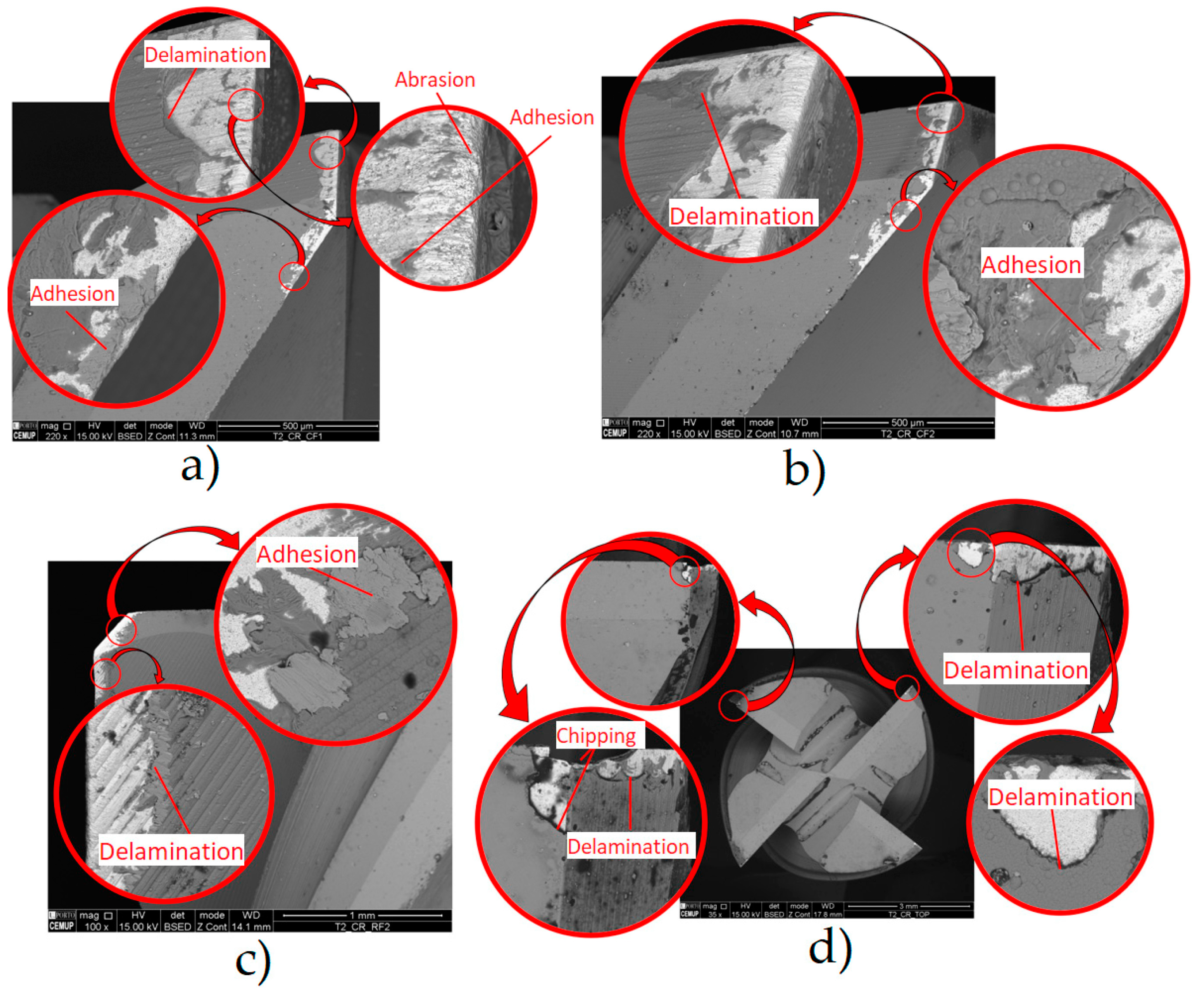
| Nogueira et al. [34] | Conducted an assessment, identification, and quantification of TW mechanisms during the machining of AMPCO® using WC-Co uncoated tools and TiAlTaN-coated tools by Physical Vapour Deposition (PVD) [101,102]. The experimental setups were conducted using an L6 array with Vc = 126 m/min; f = 750 and 1500 mm/min; Lcut = 26.8, 53.6, and 73.7 m; ap = 0.5 mm and ae = 3.6 mm. The primary objectives were to evaluate tool performance under varying Lcut and f at three distinct levels and to analyse SR on the machined surface. | For WC-Co uncoated tools, f and Lcut parameters noticeably influence the Ra values. The lowest Ra values were observed under f = 750 mm/min and Lcut = 26.8 m, while the highest Ra values were noted for f = 1500 mm/min and Lcut = 73.7 m, both longitudinally and transversely. This suggests that the superior Ra, the total height of the profile (Rt), and the maximum height of the profile (Rz) values were achieved at lower f and Lcut values, indicating that a poorer machined surface quality was obtained for higher f and Lcut values. Concerning VB, the primary wear mechanisms identified were the abrasion and adhesion of the machined material. For TiAlTaN-coated tools, the Ra values and trends were consistently higher than those of the WC-Co uncoated tools. Regarding VB, the primary wear mechanisms identified were delamination, chipping, and abrasion. | |
| INVAR-36® | Zheng et al. [103] | A trialled face milling experiment was conducted on INVAR-36® using a coated carbide. The microhardness was assessed, and the metallographic structure was observed to identify work-hardening mechanisms. | Work-hardening occurred during the face milling of INVAR-36®, ranging from 120 to 150% at a 30 μm depth. Parameters such as ap and fz significantly influenced the degree and depth of work-hardening. As these parameters increased, the depth and degree of work-hardening also increased. Upon metallographic observation, the work-hardening layer comprised two distinct regions: the thermal-force-influenced and force-influenced. |
| Cornelius et al. [104] | These authors elucidated the definition and transfer of the coordinate system for the five-axis machining of additively manufactured preforms. The practical application of this method was demonstrated through the precision machining of a mould for a Carbon Fibre-Reinforced Polymer (CFRP) layup fabricated from an additively manufactured INVAR-36® preform. | The utilization of this technique holds the potential to enhance accuracy, minimize material wastage, and reduce the overall machining cycle time. However, the final machined component proved unsuitable when applied to the Wire Arc Additive Manufactured (WAAMed) INVAR-36® preform examined in this study. This outcome was attributed to several inherent challenges associated with additively manufactured parts, including warping, internal stresses, and porosities. | |
| Gil Del Val et al. [105] | A study characterizing the machinability of INVAR-36® samples produced through Wire Arc Additive Manufacturing (WAAM) technology was proposed, employing Minimum Quantity Lubrication (MQL) during the finishing milling process. | The SR values of WAAM samples are minimal under all cutting conditions, despite a 9% increase in average Fcut compared to wrought samples, attributed to the higher hardness level of WAAM samples (20%). Furthermore, the statistical analysis not only underscores the negligible influence of Vc on machinability but also identifies the optimal roughness value (0.8 µm) achieved at Vc = 50 m/min and fz = 0.06 mm/tooth. Ultimately, the predominant wear mechanism observed during the finishing milling of WAAM INVAR-36® samples is adhesion on the rake and clearance faces (RF and CF). | |
| HT Steels | Arruda et al. [3] | This work aimed to optimize Ra on AISI H13 (DIN 1.2344) steel, using a ball nose end mill, during finishing milling. Ra was evaluated in two cutting directions. | The ball nose end mills can effectively produce suitable Ra values for manufacturing moulds and dies when used for the finishing milling of AISI H13 hardened steel. The outcomes of this investigation can be applied in the finishing milling process of AISI H13 hardened steel using ball nose end mills to obtain consistent Ra values that are robust against noise factors. |
| Singh et al. [106] | The impact of machining parameters during the milling of AISI H11 (DIN 1.2343) was assessed by evaluating SR and MRR. TGRA with a standard L27 orthogonal array was conducted to determine the optimal milling setup. Data analysis was conducted using Microsoft® Excel™ software, and the significance of the model was assessed using the ANOVA method. | (1) Vc emerges as the sole significant machining parameter affecting SR. Increasing Vc leads to enhanced SR. (2) Vc, f, and ap significantly influence the MRR, which rises with increasing values of the input parameters. These parameters are significant factors impacting the composite response, comprising SR (with a weightage of 0.2) and the MRR (with a weightage of 0.8), albeit with unequal weighting. (3) In rough machining conditions, f is the most influencing, followed by ap and Vc. (4) Vc and f emerge as significant parameters in finishing conditions, while ap is deemed insignificant. | |
| Şahinoğlu [107] | This author investigated the vibration, energy consumption, power consumption (Pin), and SR values during the machining of AISI H11 (DIN 1.2343) tool steel under cryogenic CO2 (l), coolant, and dry cutting lubricating environments. | Vibration values increase with extreme cutting parameters, with the highest vibration occurring during CO2 (l) cutting. The coolant environment exhibits the slightest vibration. f is determined to be the most influential parameter on SR. The optimal cutting conditions for reduced vibration and SR values were identified as ap = 0.2 mm, Vc = 175 m/min, and f = 0.119 mm/rev with coolant lubrication. Under these conditions, vibration, SR, and Pin were reduced by 5.18%, 37.12%, and 36.19%, respectively, and machine efficiency increased by 7.16%. It is noteworthy that other authors have also studied the subject of machining vibrations [108,109] regarding other materials. | |
| Platt et al. [110] | These authors conducted a study on the High-Feed Milling (HFM) of surface structures in components made of AISI H11 (DIN 1.2343) hot work tool steel (HWS). The process’s performance was assessed through Fcut measurements and TL tests. The resulting surface topography was measured and assessed based on the quality of the structure and roughness parameters. | Vc = 200 m/min resulted in reduced Fcut and TW development compared to Vc = 100 m/min. Higher values for the lead angle (βf) also contribute to decreased Fcut while altering the resulting structure geometry. Increasing ap reinforces these trends. Significant differences are observed in the achievable Rz and their qualitative geometry, along with anisotropies in the structure formation, concerning the surface topography. Additional investigations are required to assess burr formation associated with VB in HFM. | |
| Wojciechowski et al. [111] | During the precise ball-end milling of AISI L6 (DIN 1.2714) alloy steel, the ploughing phenomenon was assessed by analysing Fcut at the interface between the tool flank face and the workpiece. A novel ploughing Fcut model was developed for ball-end milling, accounting for the influence of the minimum uncut chip thickness (hmin) and the ploughing volume. | The ploughing Fcut was significantly higher when milling with a worn tool, due to the irregular non-circular profile of the cutting edge below the stagnant point and the presence of attrition and micro-grooves on the tool flank face. The angle that represents the slope of the machined surface was found to have a non-linear impact on the estimated values of hmin and k. When using a worn tool, VB = 150 μm [112], it was observed that the hmin value increased, directly linked to the significant growth of the cutting-edge radius. | |
| Abu Bakar et al. [113] | These authors conducted an experimental study to investigate TW mechanisms during the dry and cryogenic N2(l) milling of AISI H13 (DIN 1.2344) steel, employing different cutting-edge radii. The objective was to examine how the cutting-edge radius influences the TW mechanism of uncoated carbide-cutting tools with rounded edges. | The milling setup is determined by Vc = 200 m/min, fz = 0.03 mm/tooth, and ap = 0.1 mm for dry and cryogenic N2(l) cooling environments. Milling using N2(l) with a tool that has a cutting-edge radius of Rn = 0.03 mm enhances the performance of an uncoated carbide tool during the milling of AISI H13 (DIN 1.2344) steel. This reduces TW rates and extends TL compared to dry machining with a commercial tool of Rn = 0.018 mm. N2(l) dissipating heat efficiency delays the development of TW. A larger cutting-edge radius significantly impacts the TL, attributed to the higher VB generated at a sharper cutting edge. Analysis using Field-Emission Scanning Electron Microscopy (FESEM) revealed that abrasive and adhesive wear were the predominant wear mechanisms observed under dry and cryogenic N2(l) milling, being more pronounced in dry machining due to high T. |
| Material | Author | Challenges | Remarks |
|---|---|---|---|
| AMPCO® | Sharma et al. [121] | These authors employed a molecular dynamics simulation to investigate the interaction between the tool and hard particles during the nano-orthogonal cutting of CuBe. They observed that including hard particles within the workpiece materials influences the cutting process, impacting surface formation, material deformation, and TW mechanisms. | The position and dimensions of a hard particle are determining factors in surface formation and subsurface damage. Fcut experienced sudden increases, leading to surface deterioration. Subsequently, the particle rebounds after the tool passage, causing protrusions on the surface. Shockley partial dislocations emerge as the primary plastic deformation mode during CuBe cutting. If the particle size exceeds the sharpness of the cutting edge, dislocations glide into the bulk material, resulting in subsurface damage. The interaction between hard particles and the diamond tool during cutting amplifies equivalent stresses, resulting in the removal of carbon atoms from the tool. The density of dislocations is highest for the (111, 〈110〉) orientation and lowest for the (100, 〈100〉) orientation. A more significant degradation of the tool edge is observed in the last referred orientation. |
| Sharma et al. [31] | These authors examined the mechanisms involved in machining Cu and CuBe alloys by analysing imprints on the tools and machined surfaces. In addition, the authors investigated factors such as TL, wear patterns, changes in the diamond tool’s phase, and the interactions between the tool and workpiece materials during the machining process. | (1) CuBe has a high VB rate, which means that the roughness increase is also high as a reflection of the rate affecting the surface. (2) Because of the high VB rate, the increase in Ra is approximately 300% compared to the initial values. (3) Comparing Cu with CuBe, the latter has a much higher wear rate. (4) The TL and Ra of CuBe are 52% higher than Cu. (5) The primary mechanism responsible for wear at the edge of diamond tools is stress-induced amorphization, which transforms the diamond material from a crystalline to amorphous state. | |
| INVAR-36® | Zhao et al. [122] | These authors focused on the cutting performance of ceramic cutting tools in wet turning the INVAR-36® alloy, including TL, Ra, and failure mechanisms. The optimal cutting parameters were determined using an orthogonal test and range analysis. | Parameter ap significantly impacted the metal MRR amount, while f significantly affected Ra. The observed wear mechanisms included abrasive, diffusion, and oxidation wear. The log-normal distribution was suitable to characterize the TL distribution, with a coefficient of variation of 0.085, suggesting the TiB2-SiC ceramic cutting tools have high reliability when continuously wet turning the INVAR-36® alloy using the optimized cutting parameters. |
| Mahir [123] | The performance of three distinct tools was compared: a two-layered TiCN-Al2O3-coated tool, a single-layered TiAlN-coated tool, and one uncoated tool when machining INVAR-36®. The TW is about 30% and 60% better using the TiCN-Al2O3-coated insert than the single-layer TiAlN-coated and uncoated inserts, respectively. | (1) VB and BUE were the predominant wear mechanisms observed for all cutting tools. (2) In the machining of the INVAR-36® alloy, all tools showed a significant decrease in cutting time as Vc increased. (3) The developed first- and second-order models successfully estimated the output parameters (Fc, Ra, VB, and Pc) with a high Pearson’s correlation coefficient (R2), (4) The outcomes of this study show that the two-layer TiCN-Al2O3-coated insert significantly improves the cutting performance of the INVAR-36® alloy compared with uncoated and single-layer TiAlN-coated inserts. Multi-layer cutting tools should be used to avoid a premature loss of cutting tool performance, and cutting parameters should be selected at moderate levels. | |
| HT Steels | Suresh and Basavarajappa [124] | This work is focused on formulating a response surface methodology to represent the relationship between cutting parameters and the turning process of hardened AISI H13 (DIN 1.2344) steel (55 HRc) using TiCN-coated ceramic tools under dry cutting conditions. Mathematical models were developed to correlate machining parameters with TW and SR. | The central composite design utilized in this study has demonstrated its effectiveness in modelling TW and SR. Vc is the most significant parameter affecting TW, accounting for 47.4% of the variance, followed by f at 28.15% and ap at 15.8%. Abrasion is identified as the primary wear mechanism observed under extreme cutting conditions, while adhesion predominates at softer cutting conditions. Regarding SR, f emerges as the most influential factor, explaining 49.55% of the variance, followed by Vc at 40.3% and ap at 8.8%. SR improves with increasing Vc but deteriorates with higher f. |
| Benlahmidi et al. [125] | The impacts of Vc, f, ap, and workpiece hardness on SR, cutting pressure, and cutting power were investigated during hard turning hardened AISI H11 (DIN 1.2343) utilizing cBN7020 tools. | Factors and performance relationship measures are expressed through quadratic regression equations, enabling the estimation of the expected performance. The mathematical models demonstrate a good fit with experimental values within a 95% confidence interval. The hardness of the machined material predominantly influences the variations in output factors. This insight has facilitated the precise delineation of the hard turning domain for the proposed cBN tool and workpiece. The presented results indicate a significant improvement in SR with increasing Vc and workpiece hardness while displaying adverse effects with a higher f, although ap has a negligible influence. The optimal setup is Vc = 178.32 m/min, f = 0.08 mm/rev, ap = 0.43 mm, and a workpiece hardness of 41.73 HRc. Additionally, it was determined that TL is primarily influenced by Vc, with a 91.68% contribution and to a lesser extent by f, with a 3.83% contribution. | |
| Liu et al. [126] | TiCN-based cermets and cemented carbide tools were manufactured with a multi-layer TiN/Al2O3/TiCN/TiN CVD coating to evaluate their performance in the orthogonal cutting machining of hardened AISI H13 (DIN 1.2344) steel. | (1) An increase in Vc, ap, and f accelerates VB. Coated cermets exhibit a longer TL than uncoated ones. However, with increasing ap and f, Fcut significantly rises. Due to poor toughness, cracks are more prone to initiate and propagate in coated cermets, resulting in a shorter TL. (2) At ap = 0.2 mm and f = 0.05 mm/rev, coated cermets demonstrate the most extended lifespan when the spindle rotations (n) exceed 700 rpm. The exceptional diffusion and adhesion TW resistance of coated cermets at high T contribute to the improved SR of the workpiece. | |
| Özbek [127] | This author explored how cryogenic treatment affects the performance of cutting tools when turning AISI H11 (DIN 1.2343) steel. This treatment resulted in an increased hardness of the cutting tools. | The cutting tools that underwent deep cryogenic treatment experienced the most substantial increase in hardness, with a rise of 10.87%. The wear resistance of tungsten carbide cutting tools coated with TiCN-Al2O3-TiN was enhanced through cryogenic treatment. Tools subjected to deep cryogenic treatment demonstrated a superior wear resistance and Ra compared to those treated with shallow cryogenic treatment for six hours. As Vc increased, the cutting tools exhibited an increased VB. The abrasive TW mechanism resulted in VB on all tools, while the adhesive wear mechanism caused a built-up edge on the tools. Cryogenically treated tools induced superior Ra values on the workpieces compared to untreated tools. Tools that underwent deep cryogenic treatment for 24 h achieved the most optimal Ra. The experimental findings indicated that cryogenic treatment enhanced the cutting tool’s resistance to abrasion. |
| Material | Author | Challenges | Remarks |
|---|---|---|---|
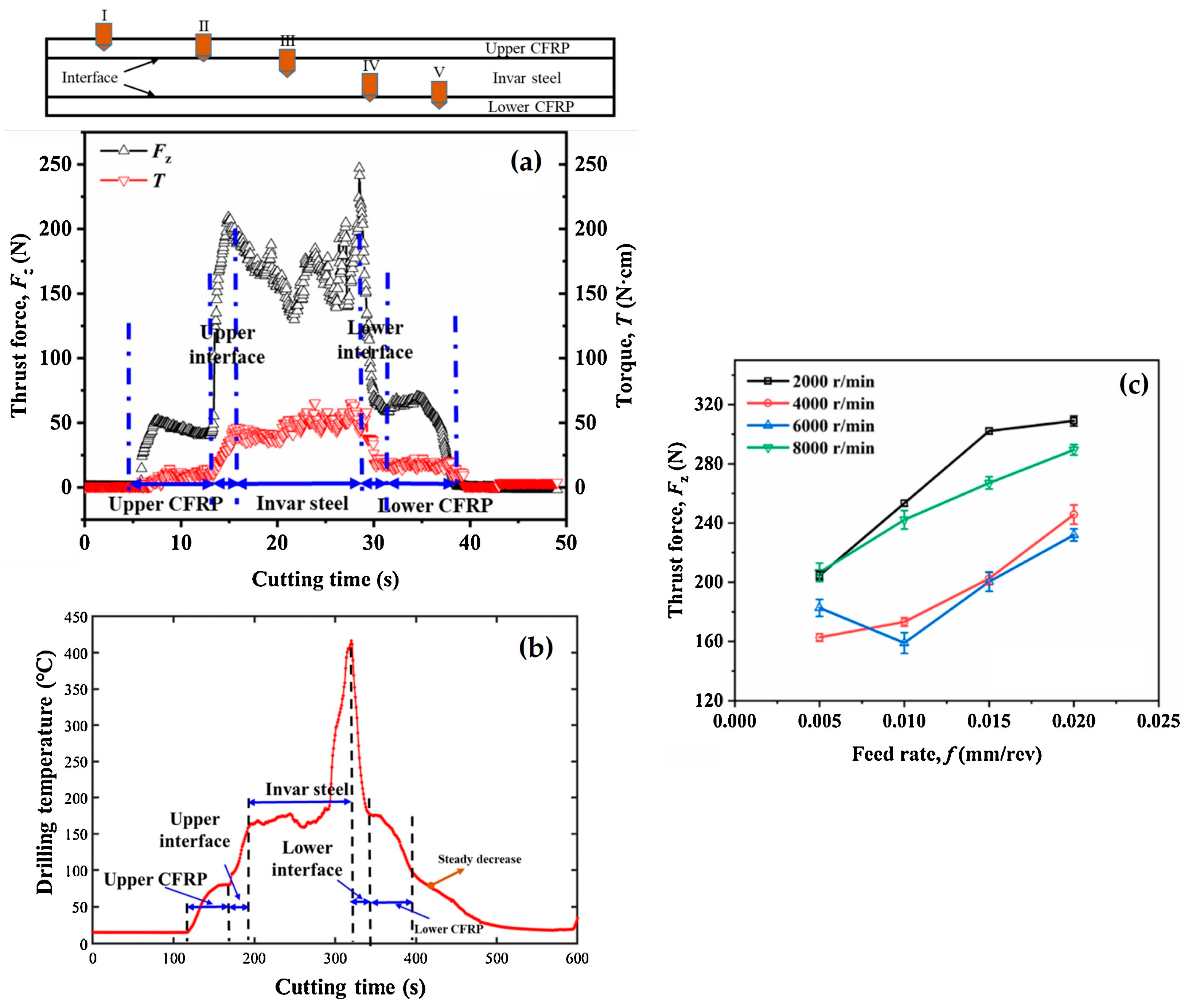
| INVAR-36® | Zhang et al. [133] | These authors endeavoured to elucidate the progression of crucial cutting phenomena, such as thrust forces, Tcut, and surface quality while drilling holes in INVAR-36®/CFRP T700 multi-material stacks, focusing on the influence of cutting parameters. Additionally, the mechanism governing the control of the interfacial drilling response was examined. PVD TiAlN-coated drills were used, and the machining levels were defined by s = 2000, 4000, 6000, and 8000 rpm/min, and f = 0.005 mm/rev, 0.01 mm/rev, 0.015 mm/rev, and 0.02 mm/rev. Only the findings about INVAR-36® will be addressed. | (1) The thrust forces and Tcut encountered during the drilling of the INVAR-36® phase surpass those observed in both the upper and lower CFRP phases (Figure 8a,c). (2) The INVAR-36® alloy’s k deviates from that of conventional engineering materials, resembling that of non-metallic materials like ceramics. Consequently, drilling INVAR-36® generates more heat during cutting, resulting in a comparatively higher Tcut. A significant amount of cutting heat is transferred to the chip, rendering the INVAR-36® alloy chip soft and susceptible to adhesive TW (Figure 8b) (3) As the drill advances, the chip from the INVAR-36® alloy accumulates and adheres to the drill bit, exacerbating the rubbing of the drill against the material. (4) Ensuring the processing quality of the INVAR-36® alloy poses challenges due to its high plasticity, toughness, and low k. |
| HT Steels | Sorgato et al. [134] | The TW and surface quality in drilling operations of multi-layered cladding were investigated, which is particularly challenging and requires further investigation. The laser cladding of AISI H13 (DIN 1.2344) tool steel layers using varying powder sizes and laser power was performed. Later, drilling tests at constant cutting parameters were conducted to evaluate drill bit wear. Additionally, the study investigated the quality of the drilled holes by analysing the internal Ra and edge contour and their relationship with TW. | The accuracy of the drilled holes’ diameter and their internal surface finish quality were evaluated. The primary wear mechanisms identified were adhesion, the coating peeling off, and laser cladding samples at the slowest scanning speed experienced BUE on the tool’s cutting edges. The improved mechanical properties obtained at lower scanning speeds generate more heat in the cutting zone, increasing BUE formation. The results indicate that the microstructural features induced by the deposition process significantly impacted the TW and the quality of the drilled hole when using laser cladding AISI H13 tool steel. The parameters used for laser cladding significantly impact TW and, consequently, the quality of the drilled hole. |
| Material | Author | Challenges | Remarks |
|---|---|---|---|
| AMPCO® | Kityk et al. [137] | Research on electropolishing bronze using an electrolyte composed of a deep eutectic solvent known as Ethaline was conducted. This solvent comprises a eutectic blend of choline chloride and ethylene glycol in a 1:2 mass ratio. Two types of bronze alloys, namely AMPCO® 22 and AMPCO® 712, were employed in the study. | Electropolishing AMPCO® 22 and AMPCO® 712 can be carried out in Ethaline at an electrode potential of +2.5 V and T = 25 °C for 20 min. The SR was reduced by 80% and 60% compared to its initial values for AMPCO® 22 and AMPCO® 712, respectively. Additionally, the electropolished surfaces of AMPCO® 22 and AMPCO® 712 showed improved corrosion resistance by nearly 30% and 10% for AMPCO® 22 bronze and AMPCO® 712 bronze, respectively. |
| INVAR-36® | Wang et al. [138] | A numerical investigation was performed to ascertain the primary factors influencing the nano-polishing characteristics of INVAR-36®. Given its low hardness and pronounced chemical reactivity, achieving superior surface quality with nanometric precision presents a formidable challenge. FEA was employed via a molecular dynamics simulation, complemented by an experimental validation of the simulation outcomes. | (1) Within the molecular dynamics simulations, elevating the polishing velocity yielded an increased MRR and mitigated subsurface damage. However, this also led to a coarser groove surface and encouraged the formation of amorphous regions. As the speed escalated further, the polishing efficiency reached a critical threshold. (2) During polishing with rolling abrasives, augmenting the rolling torque correlated with a heightened workpiece T and diminished the polishing force and MRR. (3) Rolling motion engenders a higher T, reduced MRR, and a rougher surface morphology relative to the sliding motion. At greater polishing depths, ploughing and cutting removal are the principal removal mechanisms in pure sliding processes. Conversely, ploughing manifests only at deeper polishing depths in a rolling motion, and the ploughing regime signals are less pronounced than those in a pure sliding motion. |
| HT Steels | Temmler et al. [139] | The impact of multi-step laser polishing on the microstructural characteristics of the remelted surface layer of AISI H11 (DIN 1.2343) tool steel was examined. Four distinct sets of process parameters were chosen for the laser polishing initially annealed samples composed of H11 tool steel. | Electron Backscatter Diffraction (EBSD) analysis demonstrated a refinement in grain structure, with an average size ranging from 1.1 to 1.5 μm after remelting using the laser. Surface hardness significantly increased the hardness of the initially soft annealed base material, attributed to grain refinement and the formation of martensite. SR measurements revealed Ra = 0.11 μm achieved within an Ar atmosphere. Introducing 6 vol% CO2 into the process gas atmosphere further reduced Ra = 0.05 μm. |
| Awale et al. [140] | The capability of non-destructive methods such as micromagnetic Barkhausen Noise (MBN) in evaluating grinding burn defects concerning the microstructural and mechanical characteristics of hardened AISI H13 (DIN 1.2344) die steel was discussed. The study employed an MQL lubrication grinding environment, utilizing environmentally friendly machining fluids such as Paraffin Oil (PO) and castor oil (CO) and compared their efficacy with traditional wet and dry grinding methods. | A 75% decrease in grinding T accompanied by minimal oxidation and carbonization layers, C = 3.16% and O = 1.23%, occurred at higher f = 12 m/min. This was facilitated by adequate lubrication and cooling during the wheel–work–chip interaction through the capillary penetration of castor oil-based MQL, as observed in dry grinding. The MQL-CO grinding method exhibited the lowest Ra = 0.232 μm and Rz = 1.838 μm on the surface topography. This was attributed to the superior anti-friction and anti-wear properties of CO, which mitigated ploughing and rubbing actions. Dry grinding resulted in notable alterations in the microstructure, with a thermal damage region of 55 μm and a lower microhardness, 429 HV, due to temper damage effects on the ground surface and subsurface at elevated T = 817 °C. A non-destructive assessment revealed a poor MBN signal and small envelope amplitude during MQL-CO grinding. This was attributed to the minimal impact of temper damage on the newly formed surface grains at higher work f = 12 m/min, hindering magnetic domain wall rotation. |
| Material | Author | Challenges | Remarks |
|---|---|---|---|
| AMPCO® | Yıldız et al. [147] | The thickness (t) of the white layer (WLT) that forms during the EDD of the CuBe alloy and how the WLT changes as the drilling depth increases were examined. Statistical analysis using ANOVA and significant difference methods determined that as the drilling depth, working current, and pulse duration increase, t the WLT also increases. | The working current, pulse-on time (Ton), and pulse-off time (Toff) duration primarily influence the WLT formed during the process. The depth of the drilled hole also plays a meaningful role. A second-order response surface model has been created in this study, incorporating the main and interaction effects of various influential combinations of EDD control factors and variations in hole measurements, effectively predicting the formation of the WLT’s t and optimal EDD performance with a 95% confidence interval. For thinner t achievement, using lower working currents, Ton and Toff are recommended during EDD. The authors address that future attempts should address the variations in Ra that arise due to the EDD machining depth. |
| Dong et al. [144] | In this investigation, auxiliary electrodes were employed to mitigate the impacts of stray-current corrosion on the terminal surfaces of holes in the C17200 [26] CuBe alloy. Micro-EDM was utilized as a safe and efficient machining process for working with CuBe alloys, notwithstanding their toxic properties and mechanical robustness. | The micro-EDM drilling of micro-holes on the C17200 CuBe alloy in deionized H2O reveals electrochemical dissolution and anodic oxidation occurring at the end surface of the micro-hole, directly impacting the performance and lifespan of components. The effectiveness of micro-EDM with an auxiliary electrode in mitigating stray-current corrosion on the C17200 CuBe alloy was confirmed across various pulse currents and pulse widths. Fine micro-hole end surfaces were achieved with the auxiliary electrode under 0.34 A pulse current conditions and a 20 μs pulse width. Minimal impact on electrode wear was verified with the auxiliary electrode. However, the machining time slightly increased when the pulse current was below 0.55 A and the pulse width was 20 μs. Beyond this threshold, the effect of the auxiliary electrode on machining time was less apparent. | |
| Rebelo et al. [148] | This work presented an experiment that examines how various processing parameters for the rough, finishing, and micro-finishing or polishing of EDM impact the MRR and surface quality when machining high-strength CuBe alloys. | (1) The average recrystallization rates observed in the CuBe alloy are approximately 0.1 of those in steels. (2) The average peak of the recrystallization rate is achieved at shorter on-times than that of steels, and the maximum of the curves shifted towards lower discharge times. (3) In rough regimes: Ton = 50 μs, while in finish regimes: Ton = 12.8 μs. | |
| Mouralova et al. [143] | This work aimed to optimize AMPCOLOY® 35 EDM parameters such as Vc, surface topography, and complex surface. A mathematical model was developed to determine the optimal Vc, and an optimization process was carried out using this model. The optimization aimed to achieve the maximum Vc while minimizing Ra. Equal importance was given to both objectives during the optimization procedure. | All the machined samples exhibited a similar surface morphology, regardless of the specific machine parameters used. The samples were relatively smooth and did not contain any large craters. While there were some small cracks on the surface of all samples, these were found to be purely superficial and did not extend into the cross-section of the samples. This evidence suggested that the cracks did not compromise the functionality or service life of the machined parts. The machined specimens’ surfaces display segregated lead crystals in various regions. The subsurface region of all samples was entirely free of defects, and the recast layer was thin, measuring no more than t = 15 μm and only present in localized areas. Using TEM, a lamella analysis identified an elevated concentration of alloying elements in the recast layer. The analysis also revealed a shift in crystal orientation resulting from Wire EDM (WEDM) | |
| Mouralova et al. [149] | These authors developed mathematical models to optimize the machining process of AMPCOLOY® 35 across a varying t, ranging from 5 mm to 160 mm in increments of 5 mm, employing WEDM to enhance the surface characteristics of mould parts. The Box–Behnken-type experiment design generated 448 samples. | (1) The highest Ra = 4 µm at the centre of the samples was reported, while a slightly lower value of Ra = 3.6 µm was observed at the margins. The lowest Ra = 1.6 µm was recorded in the sample machined with Ton = 6 µs, Toff = 40 µs, and a peak current (Ip) of 25 A. (2) All examined factors demonstrated positive main effects, increasing, with the interaction between Toff and Ip being the most influential. (3) Consistent with expectations, the sample with t = 5 mm exhibited the highest Wire Feed rate (WF) of 20.24 mm/min. (4) Ton and Ip positively impact Vc, while Toff had a detrimental effect. (5) Upon analysis, no discernible defects were detected in the surface morphology of the samples. Minor discrepancies between the centres and margins of the samples were observed in the size and articulation of the craters, aligning closely with the topographic analysis. | |
| Dong et al. [150] | The mill micro-ball socket technique in the C17200 [26] CuBe alloy was introduced using micro-EDM. Specifically, a linear compensation method for the tool electrode was employed, and a variable t approach was proportional to the desired outcome. The machining parameters were analysed to attain superior dimensional accuracy in producing micro-ball sockets. | The most favourable outcomes were obtained when k = 0.98 and the initial layer was t = 0.024 mm (innovative approach for manufacturing micro-ball sockets in C17200 [26]). When comparing constant t approaches, it was found that implementing a proportional variable t layered technique could significantly decrease the error rate during machining. This effect was particularly evident when the number of layers was slightly increased. The time required for machining decreased as the initial t of the material increased. Based on the evaluation of the shape precision of micro-ball sockets, an initial layer t = 0.024 mm was recommended as an ideal starting point for micro-EDM milling. This approach should be implemented alongside a linear compensation of the tool electrode and a proportional variable t method, with a k = 0.98, for ideal results. | |
| INVAR-36® | Mohanty et al. [146] | These authors systematically refined multiple input parameters for the wire EDM machining of INVAR-36®, employing TGRA for optimization. Key control parameters, including Ton, pulse-off time (Toff), servo voltage (SV), and WF, were selected to assess their impact on the MRR and SR of the INVAR-36® alloy. To achieve the optimization of the MRR and SR, a total of nine experiments were conducted using the L9 orthogonal array design. | The MRR increases with a higher WF and Ton, with SV demonstrating the most negligible impact on the MRR, contributing only 16.22%. The optimal combination of process parameters for achieving the maximum MRR comprises Ton = 25 µs, Toff = 46 µs, WF = 5 mm/min, and SV = 30 V. The SR escalates with elevations in WF and Toff, while SV exhibits minimal influence on SR, contributing only 17.97%. The ideal set of process parameters for attaining the lowest SR involves Ton = 25 µs, Toff = 19 µs, WF = 3 mm/min, and SV = 20 V. WF emerges as the most influential parameter affecting the MRR and SR, whereas SV is the least influential factor in both aspects. |
| HT Steels | Gill and Kumar [151] | The surface alloying phenomenon induced by the EDM process employing tool electrodes fabricated via powder metallurgy (PM) was explored. The study employed a TGRA with an L18 orthogonal array to determine the optimal setup for achieving the minimum SR. Experiments were conducted on the AISI H11 (DIN 1.2343) hot die steel utilizing WCu electrodes produced via the PM process. Tool polarity (P), the percentage of the alloying element in the tool (%W), Ip, Ton, duty factor (τ), and SV input parameters were considered, and their significance was analysed through ANOVA. Scanning Electron Microscopy (SEM), Energy-Dispersive Spectroscopy (EDS), and X-ray diffraction (XRD) were utilized to examine the characteristics of the machined surface. | The presence of W3C on the surface suggests a reaction between W migrated from the PM tool and C in the high-T discharge zone. A portion of Cu from the PM electrode is also transferred to the machined surface. As Cu forms a solid solution with the α-Fe phase, this phenomenon further enhances the machined surface quality and the hardness by up to 83%. This improves the surface to abrasion, extending the lifespan of press tools and dies for hot working applications. No microcracks are observed on surfaces machined with the PM tool, indicating that the alloying process does not compromise SR, which is Ra ≈ 4 μm and aligns with typical values obtained in conventional EDM processes. The optimal parameters for SR are P+, the tool with 10%W, Ip = 5 A, Ton = 100 µs, τ = 64%, and SV = 30 V, and the optimal parameters for microhardness enhancement are P+, the tool with 15%W, Ip = 15 A, Ton = 200 µs, τ = 64%, and SV = 50 V. |
| Hess et al. [152] | During the process of the AISI H11 (DIN 1.2343) EDM, the application of thermal energy leads to the formation of microstructural changes and modifications in the material of the machined component. Although a T near or above the evaporation point is generated during the discharge at the surface, the actual T decreases as the depth within the component increases. | Ablation occurs when the material is exposed to thermal loads caused by an electrical discharge, which results in the heating of the material to T, exceeding the melting and evaporation points. As a result of the structural changes occurring within the component during EDM, the material properties are modified, leading to significant impacts on the functionality and potential applications of the resulting manufactured part. The degree of austenitization became progressively less advanced, further moving deeper inside the workpiece. At the top of the material, the carbides wholly dissolved during the heating process, but as they moved towards the bottom of the heat-affected zone (HAZ), some carbides remained even after the heating process. When the T gradients and maximum temperature (Tmax) are increased, the areas of retained austenite become larger. | |
| Le [153] | The impact of various main process parameters, such as peak current (Ip) and pulse-on time (Ton) during fine finishing, as well as powder concentration (Cp), on the machined performance (MP) and recast layer properties (RLPs) of AISI H13 (DIN 1.2344) steel samples was studied in this work. The goal was to investigate how these parameters affect the quality of the finished product. | As the main process parameters are incrementally changed, both the MRR and TWR show an upward trend. There is a decrease in the percentage of the Fe element on the surface of the recast layer compared to the substrate of AISI H13 steel. While the percentage of C increases compared to the substrate layer, it remains lower than the percentage found on the surface of the recast layer in the EDM process. |
| Material | Author | Challenges | Remarks |
|---|---|---|---|
| INVAR-36® | Butkus et al. [156] | A burst mode laser was used to perform micromachining on 20–250 µm thick INVAR-36® foils to determine the best micromachining parameters for percussion drilling. The method used for drilling holes involved firing multiple laser pulses transversely onto the sample, known as percussion drilling, without moving the beam. The study examined the rate at which holes were drilled and how the quality of the holes was affected by the number of laser pulses per burst and the laser’s average power. | The micromachining efficiency significantly improved using the burst mode laser. The micromachining throughput was up to 10× higher when using the burst mode. Using a specific laser mode of repetition rate burst can enhance the efficiency of micromachining through holes. The efficiency of ablation decreases as the t of the sample increases. The efficiency of ablation decreases for thick samples. In general, generating burst pulses for micromachining appears to be a promising approach to achieve faster and more efficient results while maintaining a similar level of quality. |
| Hauschwitz et al. [58] | Choose INVAR-36® for high-quality micrometre-scale patterns within metal shadow masks, like OLED displays, because of its exceptional characteristics, precisely its low k. | The optical module’s attributes enable the rapid alignment of the setup to achieve a consistent intensity distribution throughout the entire pattern and facilitate focus adjustments. Through the identification of the ablation edge, optimal pulse counts, and fluence levels, a suitable processing range can be determined to achieve effective, high-quality drilling and cutting with minimal heat-affected zones. | |
| Chung et al. [157] | An ultrashort pulsed laser system was highly recommended for micro-hole drilling in INVAR-36®, as it minimized the adverse effects of heat and produced high-quality edges. | An Nd:YAG laser is the preferred method to create a hole in INVAR-36®. Although it has the drawback of producing burrs at the edges that necessitate further processing, the study decided to employ an ultrashort pulsed laser instead. As the pulse energy increased, the area removed during the ablation of INVAR-36® reached a point of gradual stabilization. | |
| Choi et al. [158] | The impact of focal plane adjustments, achieved through vibration, on the quality of the INVAR-36® alloy’s fabrication during femtosecond laser hole drilling was examined. This process is used to create high-quality metal masks. The ability to control the taper angles during femtosecond laser hole drilling makes it a promising technique for the accurate micromachining of various intelligent devices. | The processing efficiency and productivity were maximized when the initial laser pulse was directed towards the sample’s upper surface, resulting in the most profound processed depth. Therefore, synchronizing the laser and vibrator in the hole processing system can significantly impact overall productivity. Decreasing the vibrator amplitude during femtosecond laser hole machining increased the taper angle of the processed hole. These findings indicate that the hole’s taper angle can be effectively managed by adjusting the amplitude of the continuously operating vibrator. | |
| HT Steels | Rubaiee [159] | The authors LDMed a 0.44 mm thick AISI H13 (DIN 1.2344) using 100 m fibre laser beams. The Complex Proportional Assessment (COPRAS) method optimizes the fibre laser settings for drilling holes. ANOVA was conducted to validate the model, and ANN was utilized to forecast the experimental outcomes. | Laser power emerges as the most critical factor influencing the quality of drilled holes. Under the optimal setup, the drilled holes exhibit Ra = 4.27 µm, a heat-affected zone of 89.89 µm, and an overcut of 139.60 µm. The experimental results indicate a close match between the observed and predicted values, and the optimal conditions yield a superior surface precision compared to the initial trials. |
| Positive Factors | Negative Factors | |
|---|---|---|
| Internal factors | Strengths High MRR: Milling processes, especially optimized, can achieve a high MRR, allowing for efficient material removal, which is particularly advantageous for large-scale production. Surface Finish Improvement: By selecting optimal parameters, milling operations can yield an improved surface finish, enhancing the quality and appearance of the final products. Adaptability: Milling processes can be adapted to various materials, including AMPCO®, INVAR-36®, and HT steels, showcasing versatility in machining different injection mould materials. TW Mechanism Understanding: Extensive research has provided insights into the TW mechanisms during milling, enabling a better understanding and management of tool longevity and performance. | Weakness SR Variation: Achieving consistent surface finish across different materials and machining conditions can be challenging, leading to SR variations and impacting part quality. TW: Especially in HSM operations, it can lead to reduced TL and decreased machining accuracy over time. Challenges with AM Preforms: The machining of additively manufactured preforms, such as WAAM INVAR-36®, presents inherent challenges like warping, internal stresses, and porosities, affecting machining accuracy and surface finish. |
| External factors | Opportunities Advanced Coatings: The integration of advanced coatings, such as TiAlTaN, can enhance tool performance and prolong tool life, offering opportunities for improved efficiency and cost savings in milling operations. Optimization Techniques: Advanced optimization techniques like Taguchi methods and response surface analysis (RSA) can help identify optimal milling parameters, maximizing the MRR and surface finish while minimizing TW. Application in Various Industries: The versatility of milling processes makes them applicable across diverse industries, including aerospace, automotive, and manufacturing, offering opportunities for market expansion and growth. | Threats Material Complexity: Machining AMPCO®, INVAR-36®, and HT steels require precision and expertise due to their unique material properties, posing challenges in achieving desired machining outcomes. Environmental Concerns: HSM operations may consume significant energy and produce waste, raising environmental concerns. Competitive Landscape: The milling industry faces competition from alternative machining methods and emerging technologies, which may offer more efficient or cost-effective solutions, posing a threat to traditional milling processes. |
| Positive Factors | Negative Factors | |
|---|---|---|
| Internal factors | Strengths Advanced Tool Coatings: Utilization of advanced tool coatings such as TiCN-Al2O3-TiN and TiCN enhances wear resistance and improves tool lifespan, contributing to efficient machining of materials like AMPCO®, INVAR-36®, and HT steels. Optimized Cutting Parameters: Studies have developed mathematical models and response surface methodologies to determine optimal cutting parameters, leading to improved MRR and surface finish, particularly in turning of INVAR-36® and hardened steels. Hardness Enhancement: Cryogenic treatment of cutting tools increases hardness and wear resistance, resulting in prolonged TL and enhanced surface finish, especially when machining materials like AISI H11 steel. TW Mechanism Analysis: In-depth investigations into mechanisms of TW, including abrasion, diffusion, and oxidation, provide insights into performance of cutting tools when turning AMPCO®, INVAR-36®, and HT steels, facilitating better tool selection and process optimization. | Weakness High TW Rate: Materials like CuBe alloys exhibit high rates of TW, leading to increased SR and decreased TL, which may pose challenges in achieving desired machining outcomes. Limited TL: Despite advancements in tool coatings and treatments, certain materials, such as CuBe alloys, may still result in significant TW and reduced TL, impacting machining efficiency and cost-effectiveness. |
| External factors | Opportunities Further Research and Development: Continued research into advanced tool materials, coatings, and cutting strategies can lead to more robust cutting tools tailored for specific materials like AMPCO®, INVAR-36®, and HT steels, enhancing machining efficiency and quality. Process Optimization: Optimization of cutting parameters and tool geometries based on comprehensive studies can further improve material removal rates, surface finish, and tool lifespan, offering opportunities for enhanced productivity and cost savings in machining operations. | Threats Material Complexity: Materials like CuBe alloys with hard particles embedded within them pose challenges in machining due to their complex microstructures and high TW rates, potentially leading to increased TW and reduced machining efficiency. Tool Degradation: Despite advancements in tool coatings and treatments, factors such as high Vc and f can still lead to rapid tool degradation and reduced tool performance, posing challenges in maintaining consistent machining quality and productivity. |
| Positive Factors | Negative Factors | |
|---|---|---|
| Internal factors | Strengths Advanced Coated Drills: Utilization of advanced PVD TiAlN-coated drills enhances wear resistance and prolongs tool lifespan, contributing to efficient drilling of materials like INVAR-36®, particularly in multi-material stacks. In-depth Phenomena Analysis: Studies have provided insights into crucial cutting phenomena such as thrust forces, Tcut, and chip formation during drilling operations, aiding in understanding challenges associated with drilling materials like INVAR-36®. | Weakness Challenging Material Properties: Materials like INVAR-36® pose challenges in drilling operations due to their high plasticity, toughness, and low k, leading to increased Tcut and chip adhesion, which may impact drilling performance and tool lifespan. Complex TW Mechanisms: Drilling multi-layered claddings and materials with varying microstructural features induces complex TW mechanisms, including adhesion, coating peeling, and BUE formation, which may affect drilling quality and tool integrity. |
| External factors | Opportunities Optimized Laser Cladding Parameters: Further research into laser cladding parameters, such as powder sizes and power, can optimize material properties and microstructural features, potentially reducing TW and improving drilling quality for materials like AISI H13 tool steel. Enhanced Tool Coatings: Development of advanced coatings and treatments for drill bits tailored to specific properties of AMPCO®, INVAR-36®, and HT steels can improve wear resistance and tool lifespan, offering opportunities for more efficient drilling operations. | Threats Increased TW: Drilling operations involving materials like INVAR-36® and multi-layered claddings may increase TW due to high Tcut and chip adhesion, posing challenges in maintaining drilling performance and tool integrity. Quality Control Challenges: Ensuring drilling quality and dimensional accuracy of drilled holes in materials with complex microstructural features may be challenging, particularly in multi-material stacks or laser-clad components, where variations in material properties can impact drilling performance and hole quality. |
| Positive Factors | Negative Factors | |
|---|---|---|
| Internal factors | Strengths Advanced Electrochemical Techniques: The use of advanced electrochemical methods, such as electropolishing with an Ethaline electrolyte, offers efficient surface polishing solutions for materials like AMPCO® 22 and AMPCO® 712, resulting in significant reductions in SR and an improved corrosion resistance. Innovative Numerical Investigations: Numerical investigations provide insights into the nano-polishing characteristics of materials like INVAR-36®, helping to understand the primary factors influencing surface quality and guiding the development of effective polishing strategies. | Weakness Complex Surface Interactions: The surface polishing of materials like INVAR-36® and AISI H11 tool steel involves complex interactions between polishing parameters, material properties, and tooling, leading to challenges in achieving desired surface finishes without introducing subsurface damage or compromising material integrity. Dependence on Process Parameters: Surface polishing techniques, such as laser polishing, are highly dependent on accurate process parameters, and deviations from optimal conditions can result in variations in surface quality, microstructural characteristics, and mechanical properties, impacting the overall polishing effectiveness. |
| External factors | Opportunities Multi-Step Polishing Techniques: Multi-step laser polishing offers opportunities to tailor surface properties and microstructural characteristics, enabling the production of surfaces with an enhanced hardness, reduced SR, and improved microstructural integrity. Non-Destructive Evaluation Methods: Integrating non-destructive evaluation methods, such as MBN, provides opportunities to assess the surface quality, detect defects, and evaluate material characteristics without compromising the integrity of the polished surface, enhancing quality control and process monitoring capabilities. | Threats Surface Damage and Defects: Surface polishing processes may inadvertently introduce surface defects, such as subsurface damage, thermal damage, or oxidation layers, particularly in materials like hardened AISI H13 die steel, posing challenges in achieving the desired surface quality and integrity. Environmental Impact: Surface polishing techniques, especially those involving traditional lubrication fluids or abrasive materials, may pose environmental risks due to the generation of waste products or the use of potentially hazardous chemicals, necessitating sustainable and eco-friendly polishing alternatives to mitigate environmental impact. |
| Positive Factors | Negative Factors | |
|---|---|---|
| Internal factors | Strengths Process Optimization: Research studies have developed mathematical models and conducted optimization procedures to enhance EDM parameters for materials like AMPCOLOY® 35 and INVAR-36®, leading to an improved machining efficiency, surface quality, and dimensional accuracy. Surface Alloying: The EDM process with PM tool electrodes has shown the potential for surface alloying, enhancing surface properties such as hardness and abrasion resistance, which can extend the lifespan of injection mould components made from materials like AISI H11 and other HT steels. Microstructural Modifications: EDM induces microstructural changes in materials like AISI H11 steel, leading to modifications that can enhance material properties and functionality, offering opportunities for tailored material characteristics in injection mould applications. | Weakness Surface Defects: EDM processes may result in surface defects such as cracks, craters, or recast layers, particularly when machining materials like CuBe alloys, posing challenges in achieving desired surface quality and integrity. Complex Parameter Interactions: The interaction between EDM parameters, such as pulse current, pulse duration, and electrode composition, can be complex, making it challenging to optimize machining processes effectively and consistently. |
| External factors | Opportunities Optimization and Process Control: Continued research into EDM parameters and process optimization techniques, such as response surface modelling and statistical analysis, presents opportunities to improve machining efficiency, enhance surface quality, and minimize defects for AMPCO®, INVAR-36®, and HT steels. Innovative Machining Strategies: Exploring EDM techniques, such as auxiliary electrodes, variable t approaches, and PM tool electrodes, offers opportunities to mitigate process challenges, improve dimensional accuracy, and enhance SR for PIM. | Threats Material-Specific Challenges: Each material, including AMPCO®, INVAR-36®, and HT steels, presents unique challenges during EDM, such as stray-current corrosion, recast layer formation, and microstructural changes, which may limit process capabilities and require tailored machining strategies. Environmental Considerations: EDM processes involve dielectric fluids and may generate hazardous waste products, posing environmental risks and regulatory challenges, necessitating sustainable machining practices and waste management strategies. |
| Positive Factors | Negative Factors | |
|---|---|---|
| Internal factors | Strengths High Precision Machining: LBD offers exceptional precision, allowing for the creation of micro-holes and intricate patterns with minimal heat-affected zones, making it suitable for manufacturing intricate components used in injection moulds. Versatility in Material Compatibility: LBD can be effectively applied to a wide range of materials, including AMPCO®, INVAR-36®, and HT steels, due to its ability to adjust parameters such as pulse energy and repetition rate to match the specific material properties. | Weakness Surface Quality Considerations: Despite its precision, LBD may produce burrs or heat-affected zones, particularly in HT steels, which could require additional post-processing steps to achieve the desired surface quality. Complex Process Optimization: Optimizing LBD parameters, such as pulse energy, repetition rate, and focal plane adjustments, can be challenging and require thorough experimentation and analysis to achieve optimal results for different materials and hole geometries. |
| External factors | Opportunities Advanced Laser Technologies: Continual advancements in laser technologies, such as ultrashort pulsed and burst mode lasers, offer opportunities to enhance drilling efficiency, reduce heat-affected zones, and improve surface quality for INVAR-36® and HT steels. Process Control and Automation: Integrating advanced control systems and automation technologies can streamline LBD processes, increase productivity, and ensure consistent quality in producing injection mould components. | Threats Material-Specific Challenges: Each material, including INVAR-36® and HT steels, presents unique challenges during LBD, such as variations in thermal conductivity and susceptibility to heat-induced defects, which may limit process capabilities and require tailored machining strategies. Cost and Equipment Requirements: LBD equipment and maintenance costs can be significant, particularly for advanced laser systems, which may pose a barrier to entry for small-scale manufacturers or those with limited resources. |
Disclaimer/Publisher’s Note: The statements, opinions and data contained in all publications are solely those of the individual author(s) and contributor(s) and not of MDPI and/or the editor(s). MDPI and/or the editor(s) disclaim responsibility for any injury to people or property resulting from any ideas, methods, instructions or products referred to in the content. |
© 2024 by the authors. Licensee MDPI, Basel, Switzerland. This article is an open access article distributed under the terms and conditions of the Creative Commons Attribution (CC BY) license (https://creativecommons.org/licenses/by/4.0/).
Share and Cite
Pedroso, A.F.V.; Sebbe, N.P.V.; Silva, F.J.G.; Campilho, R.D.S.G.; Sales-Contini, R.C.M.; Costa, R.D.F.S.; Barbosa, M.L.S.; Nogueira, F.R. A Concise Review on Materials for Injection Moulds and Their Conventional and Non-Conventional Machining Processes. Machines 2024, 12, 255. https://doi.org/10.3390/machines12040255
Pedroso AFV, Sebbe NPV, Silva FJG, Campilho RDSG, Sales-Contini RCM, Costa RDFS, Barbosa MLS, Nogueira FR. A Concise Review on Materials for Injection Moulds and Their Conventional and Non-Conventional Machining Processes. Machines. 2024; 12(4):255. https://doi.org/10.3390/machines12040255
Chicago/Turabian StylePedroso, André F. V., Naiara P. V. Sebbe, Francisco J. G. Silva, Raul D. S. G. Campilho, Rita C. M. Sales-Contini, Rúben D. F. S. Costa, Marta L. S. Barbosa, and Francisca R. Nogueira. 2024. "A Concise Review on Materials for Injection Moulds and Their Conventional and Non-Conventional Machining Processes" Machines 12, no. 4: 255. https://doi.org/10.3390/machines12040255