Abstract
Gear transmission systems are widely used to transfer energy and motion and to guarantee the accuracy of the entire machine system. The modification technique is a common method that improves the gear profile and reduces the transmission error. Based on the parametric model, a modified gear can be established for the evaluation of static and dynamic characteristics. The influences of profile modification parameters and gear parameters are investigated while changing the rules of different kinds of factors. Based on sensitive parameters, a two-stage profile modification curve is proposed to improve the performance of gear pairs. Thus, considering the time-varying mesh stiffness and backlash, a novel, dynamic modified gear model is established to analyze the dynamic performance, such as the dynamic transmission error. Based on the proposed curve, the range and amplitude of the transmission error can be decreased. Additionally, the vibration displacement and noise can be reduced to improve the running characteristics.
1. Introduction
As the most widely used form of mechanical transmission, gear transmission systems play an important role in machine tools, and the accuracy of gear drives largely guarantees the accuracy of the entire machine system. It has been shown that gear tooth modification is effective for reducing the transmission error and improving the dynamic performance. The tooth modification method has always attracted different researchers’ attention with regard to gear trains. The curve of a parabola [1] was taken as the modified curve to improve the tooth surface of the pinion in a transmission system. A gear model with tooth profile modification was analyzed with different parameters, and the effects of the tooth profile modification on mesh stiffness were investigated [2]. Considering the coupling flexibility of the gear body, tip relief modification [3] was investigated to optimize the tooth profile by an analytical model. Based on alignment errors, an effective axial modification method of straight bevel gears was proposed to reduce the contact force and bending stress [4]. A theoretical model and the Monte Carlo method were investigated in terms of gear modification and the transmission process considering various machining errors [5,6]. Considering tooth profile modifications in sun–planet and ring–planet meshes, tooth profile modification was utilized to decrease the spur planetary gear vibration [7]. A comprehensive modification method [8] was proposed to improve the transmission process of different gears, and the mesh behavior of the gear surface was analyzed. The finite element analysis (FEA) method was utilized to establish a precise tooth profile modification approach for gear pairs [9]. The type and amount of the modified value were accurately determined by the static-contact FEA results. A finite element model with tip relief modification was developed to obtain the static transmission error for several angular configurations at different torques [10]. Based on the lateral–torsional–pendulum coupling nonlinear dynamic model, a gear transmission system and the corresponding dynamic optimization modification technology [11] were investigated to improve the tooth profile and the load factor of a driving wheel. An experimental study was utilized to optimize the geometrical features of spur gear pair teeth to minimize the system vibration [12,13]. The analytical method, finite element analysis, and an experimental study were utilized to establish the modified curve for different modes of tooth profiles in gear transmission systems.
According to the modification curve, the effects of the modified parameters and structural parameters were investigated. Parametric influences were analyzed for a modified gear on the basis of a novel two-part gear tribo-dynamic model considering tooth profile modification [14]. Different factors have been considered to address the influences between parameters and operating characteristics. The severity of vibration and noise under different operating conditions has been measured by different metrics, namely, dynamic mesh force, dynamic tooth force, and bearing force along the line-of-action direction [15]. The variation in (spur gear pair) teeth meshing stiffness due to tooth profile modification has been introduced for different amounts of transmitted torque [16]. The mesh stiffness [17], load sharing [18], and transmission error [19] of a modified gear have been investigated, and the peak-to-peak amplitude was calculated based on the analytical model [20]. Additionally, the sensitivity of tooth modification parameters was presented to reduce the transmission error fluctuations of a gear train in a wind turbine gearbox [21]. The effect of weight-reduction holes was investigated, and a polygonal approximation method was developed for mesh stiffness. Additionally, the tooth modification method was utilized to reduce the vibration [22]. Structural parameters and modified parameters have both been investigated to determine the effects of modification curves. Hence, different parameters should be considered to select a suitable parameter or optimize the curve.
Transmission error is commonly utilized to evaluate the characteristics of gear trains in different industries. The multi-tooth contact analysis of a gear train using the finite element method was used to calculate static transmission errors, which were caused by mesh stiffness, manufacturing errors, and geometric errors [23]. Static transmission errors between a standard gear and a modified gear with linear tip relief were compared to determine the effects of modification at a low velocity [24]. Additionally, a novel approach for calculating static transmission errors based on measured discrete tooth surfaces was proposed with profile modifications [25]. Novel analytical gear mesh stiffness was established to analyze the static transmission error in a gear pair [26,27]. Moreover, factors such as the variation in the contact ratio, manufacturing errors, and installation errors always result in vibration and noise that seriously affect the dynamic performance of a gear train. Both static transmission errors and dynamic transmission errors [28] are considered to influence tooth modification, which are influenced by backlash, time-varying stiffness, and damping force [29]. Hence, transmission error excitation has been investigated via the gear modification method to decrease noise. A higher-order transmission error was adopted to depict nonlinear vibration [30]. The dynamic transmission error was regarded as an important index for evaluating the system characteristics with stochastic excitations [31,32]. Additionally, time-varying factors [33] and economic factors [34] were considered to analyze the parameters’ effects on system characteristics. Based on dynamic transmission errors, a vibration-based scheme was proposed for gear wear prediction to be updated [35]. Considering static and dynamic characteristics, transmission errors should be investigated to evaluate the system performance of modified gear trains. Therefore, improving the performance of a modified gear drive is significant for improving the performance and reliability of an entire machine tool.
Tooth profile modification and its parametric influences have been investigated to improve transmission characteristics and reduce vibration and noise. In Section 2, gear modification theory is introduced, and three elements of gear modification theory are analyzed. The parametric model for the modified gear is investigated in Section 3. The finite element method is utilized to investigate the static transmission error of modified gears with different parameters. The influences of the profile modification parameters and gear parameters on the transmission error are analyzed in Section 4 and Section 5, respectively. Additionally, an optimized profile modification curve is proposed in Section 6. The dynamic model of the modified gear is established in Section 7. The corresponding dynamic transmission error and the parametric influences are investigated to reduce the gear vibration and system noise. The results indicate that only a targeted modification design under certain load conditions can lead to a satisfying modification effect and improve the transmission performance of the gear drive.
2. Gear Modification Theory
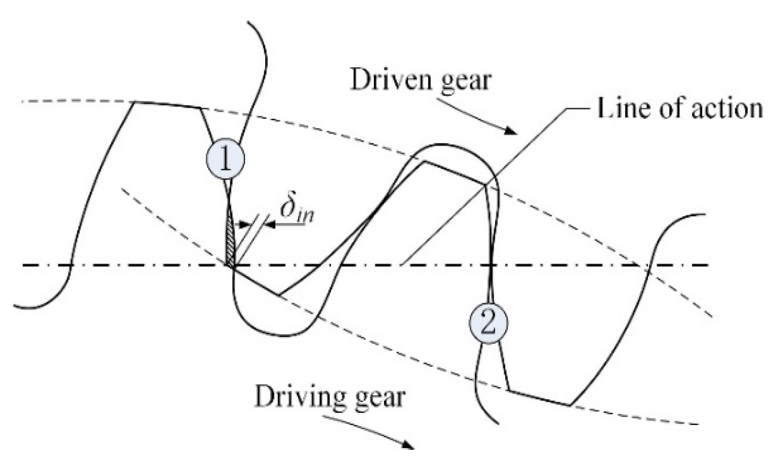
The scraping process not only causes the gear tooth to engage and produce sharp noise but also destroys the lubricating oil film and accelerates adhesive failure. To eliminate the influence of elastic deformation on the gear tooth, some parts of the gear along the direction of the tooth height are artificially removed to offset the elastic deformation, that is, the tooth profile modification. The condition of tooth interference between the driving gear and driven gear is shown in Figure 1. Parameter δ is the maximum interference value along the line of engagement, which is utilized to determine the maximum value.

Figure 1.
Schematic diagram of gear interference.
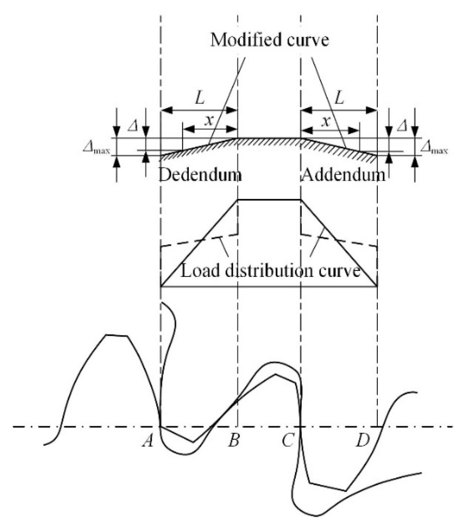
Considering gear addendum and gear dedendum, complete tooth profile modification is always utilized to optimize the load characteristics, as shown in Figure 2. Line AD is the actual length of the meshing line. AB and CD belong to the double-tooth engagement zone, and BC is the single-tooth engagement area.

Figure 2.
Schematic diagram of the tooth profile modification.
The linear modification in Equation (3) can be expressed as , in which Parameters x and L are the relative coordinates of the meshing position and modified length, respectively. Parameters Δmax and Δ represent the maximum modified value and the modified value corresponding to position x, respectively. Additionally, Walker [5] recommends the following equation: . Yoshio and Kazuteru [8] proposed a modification equation with a different parameter, . Instead of Δ and Δmax, Ca and Camax are utilized for a general formula of modification equations, as follows:
where parameter β is the modified index, which is a number greater than 1. Based on Equation (1), the modified gear can eliminate the mutant load caused by the alternation of single and double teeth. The load of gear teeth can be changed smoothly during the whole meshing process.
3. Parametric Model for Modified Gear
Considering the tip relief, the modified curve is still an involute curve, whose base radius is smaller than that of the unmodified involute curve. In Figure 3, Point C is the starting point of the modified curve in the tooth top. After the modification, the involute curve BC replaces the unmodified involute curve AC. The redundant part between AC and BC needs to be removed. The relationship between the base radius of the modified involute curve and the maximum modified value Camax can be expressed as follows:
where parameters rb and are the base radii of the standard and modified involute curves, respectively. rc and ra are the radius of the starting point in the modified involute curve and the radius of the addendum circle, respectively. Additionally, αa and αc are the pressure angles of the standard and modified involute curve.
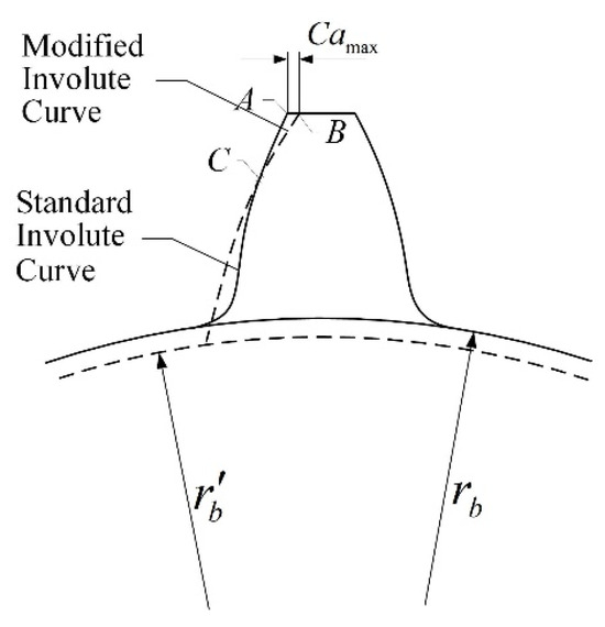
Figure 3.
Schematic diagram of the tip relief.
The involute equation can be expressed as follows:
The parameters in Equation (3) are listed in Figure 4. Hence, the involute curve of the modified gear can be explained by the following:
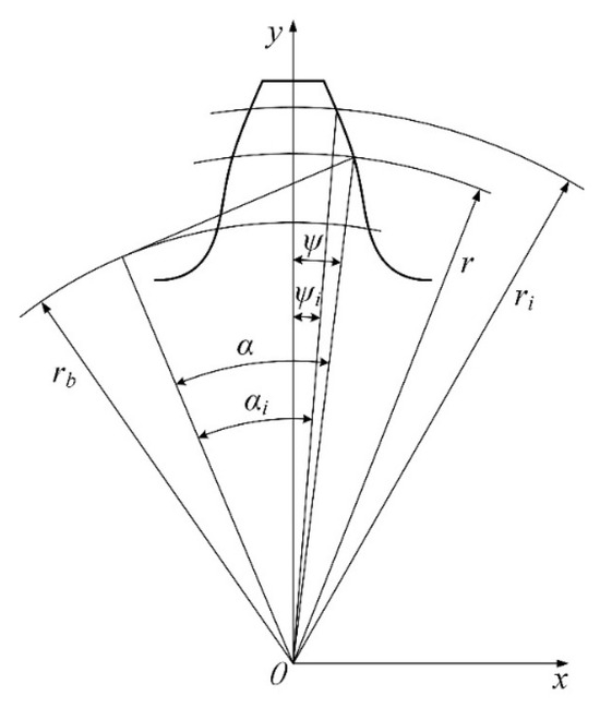
Figure 4.
Involute profile in Cartesian coordinates.
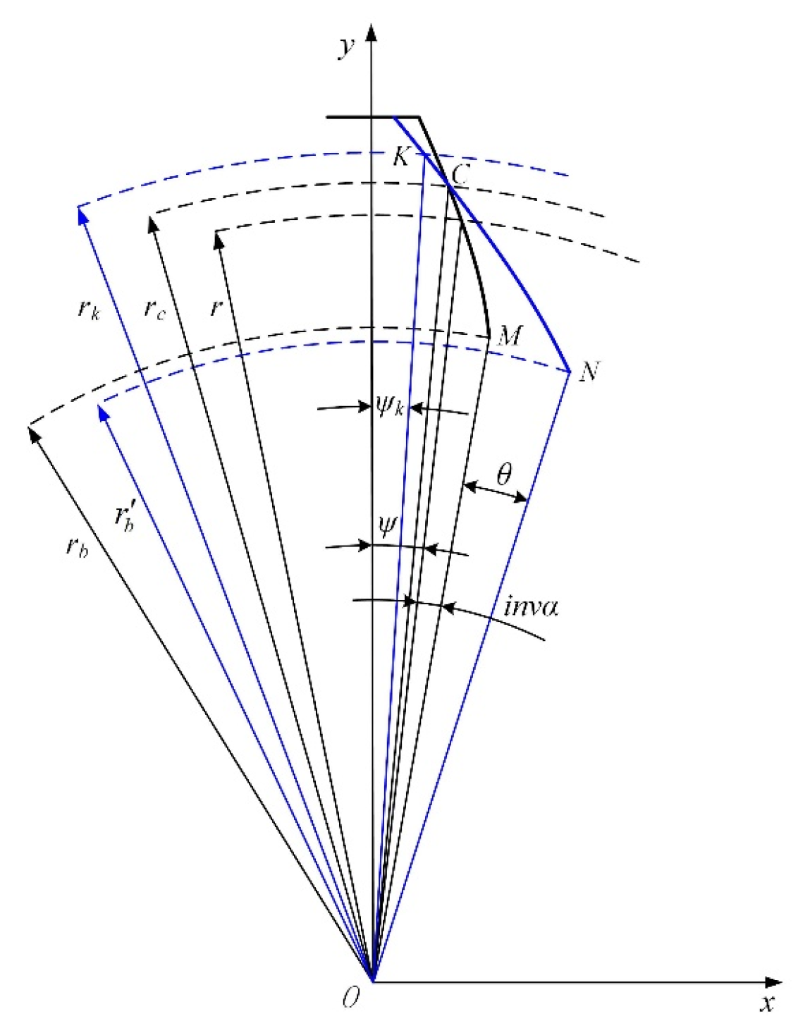
The parameters in Equation (4) are listed in Figure 5. Parameters z, r, and α represent the number of teeth, the reference circle, and the pressure angle of the reference circle, respectively. Point K represents any point located in the modified involute profile. Parameters rk and αk are the distance between Point K and Center O and the pressure angle in the modified gear, respectively. Additionally, is the pressure angle of the starting point in the modified involute curve.
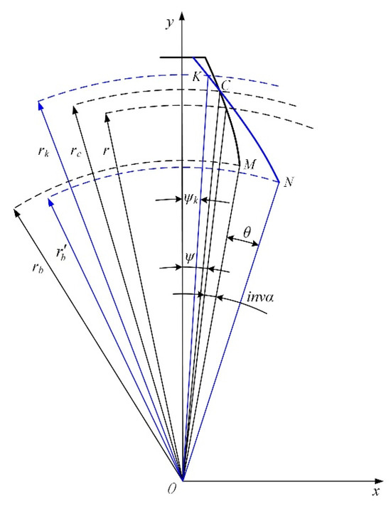
Figure 5.
Modified involute profile in Cartesian coordinates.
The modified involute profile can be depicted by the involute profile of the standard gear with different starting points. In Equation (4), Parameter αk ranges in the interval [, ], and is the pressure angle of the tip circle in the modified gear. Hence, points in the modified gear can be gained by Equations (3) and (4) to transmit smoothly. Taking Point K as an example, the modified value can be defined by Figure 6. Lines ED and KE correspond to Parameters L and x in Equation (1). The geometrical relationship in Figure 6 can be depicted by the following:
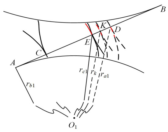
Figure 6.
Calculation of the modification value.
Hence, the modified value of Point K can be calculated by the following:
where the base pitch pb can be computed by . Based on the property of the involute curve, the K coordinate (xk, yk) is rotated around the center of the base circle at an angle λ = Ca/rb1. Point K can be computed by the following:
The parametric model for the modified gear can be established. According to Equations (6) and (7), the coordinates of all points can be depicted for the modification. The approach can be used to analyze the system characteristics of the modified gear.
4. Influences of the Profile Modification Parameters
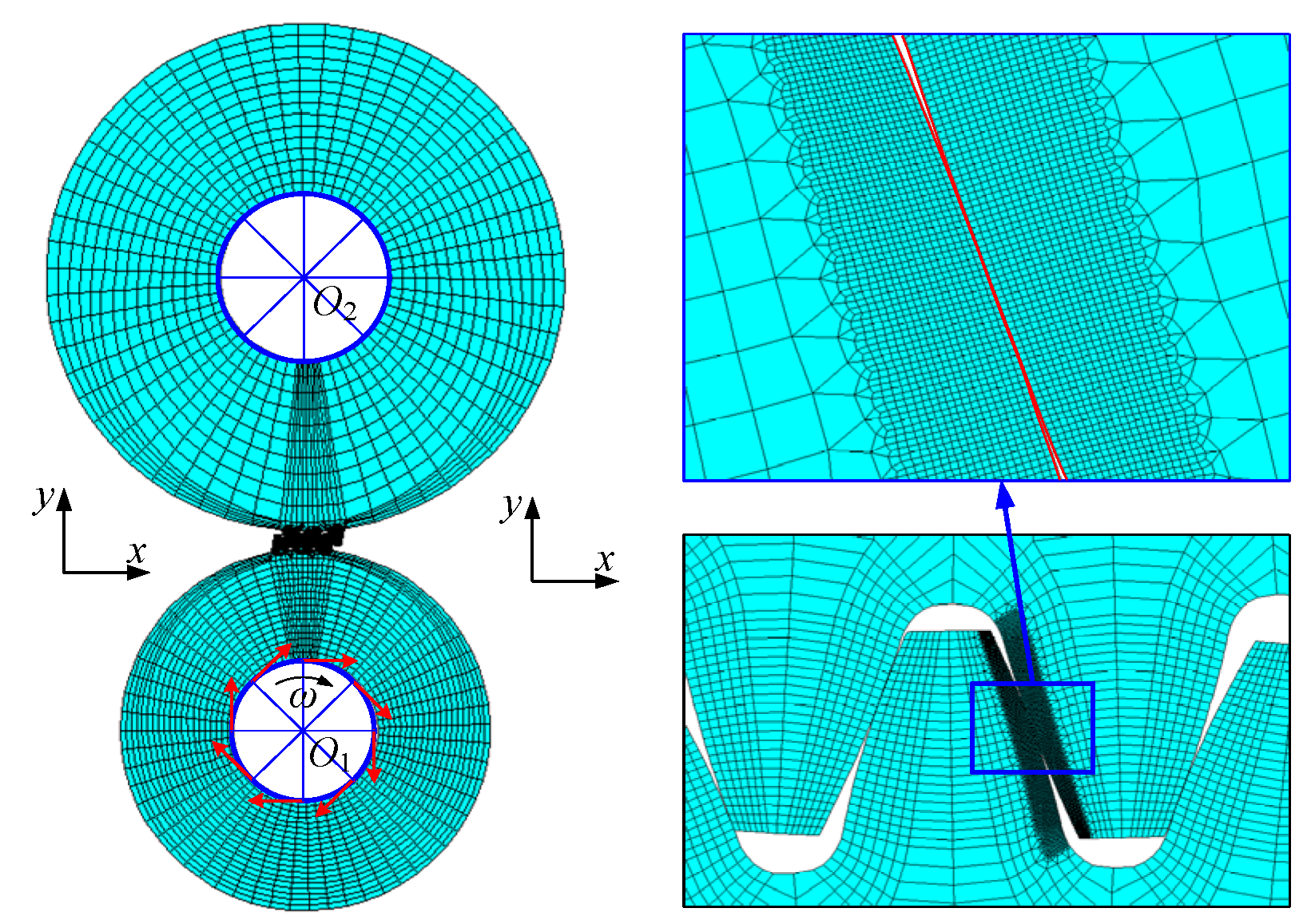
According to Section 3, ANSYS can be utilized to establish the model of the modified gear. Pinion Gear 1 is the driving gear, and Gear 2 is the driven gear in Figure 7. The transmission error is the difference between the actual position of the output gear and the theoretical position of the output gear, in which the tooth profile is an ideal involute and the tooth is not deformed. The transmission error is calculated and measured along the direction of the line of engagement in ANSYS.
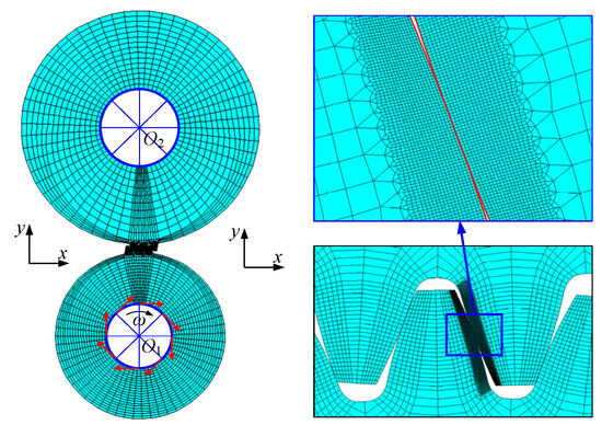
Figure 7.
Finite element model of the modified spur gear pair.
In Figure 7, a two-dimensional plane strain unit is utilized to establish the model. Several teeth are ignored for the computation cost. Also, the symmetric contact pair in ANSYS is used to depict the gear contact. All nodes of the gear hole form a rigid surface with the center node of the gear, which are the fixed constraint. Considering the torque, the deformation of the driven gear can be regarded as the static transmission error. The tooth numbers of the driving gear and driven gear are 52 and 72, respectively. Also, the modulus of each gear is 1.75. The algorithm of transmission error is shown in Algorithm 1.
| Algorithm 1: Static transmission error for the modified gear by ANSYS | |||
| Input: Number of teeth z, Modulus m, Load T, Pressure angle α. Output: Static transmission error e. | |||
| 1: | Based on input data, parameters of the corresponding standard gear can be calculated by (3), such as ri, αi, rb and ψi. | ||
| 2: | For Camax = 0, 5,…,20 do | ||
| 3: | The base radius of modified involute curve can be computed by (2). | ||
| 4: | The angle ψk of any point K (xk, yk) in the modified involute profile can be depicted by (4). | ||
| For β = 1, 1.2, 1.5, 2.0 do | |||
| 5: | The modified value of Point K can be calculated by (6). The coordinates (xk’, yk’) of points can be depicted for the modification. | ||
| 6: | Based on coordinates, establish the finite element model of the modified spur gear by ANSYS. | ||
| 7: | Solve the static transmission error e based on load T. Mesh force FN can extracted by ANSYS. | ||
| 8: | End | ||
| 9: | End | ||
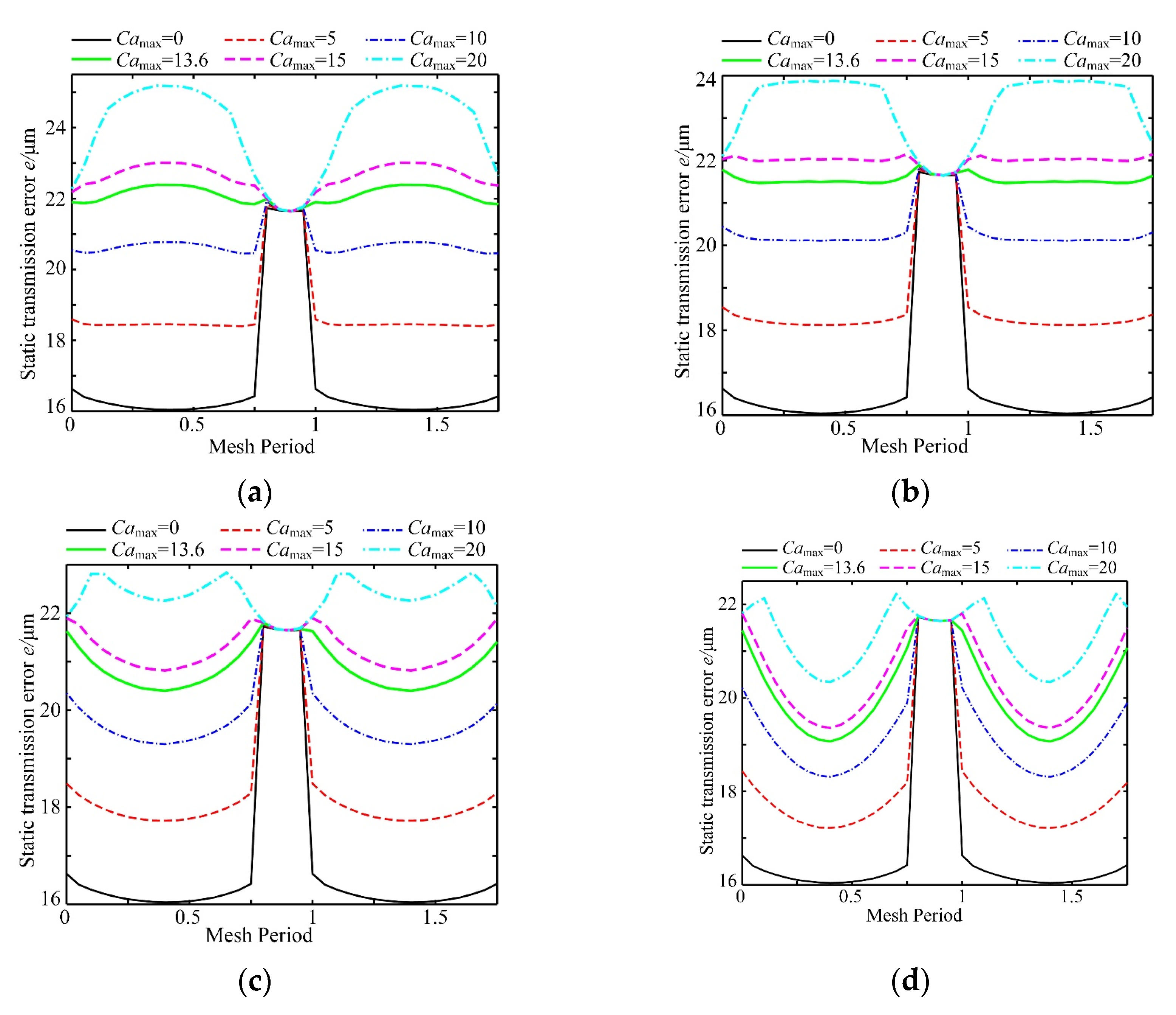
Different factors, such as external and internal factors, are investigated for tooth profile modification. According to Equation (1), the effects of Parameters β and Camax are investigated to analyze the relationship among modified gears in Figure 8. The static transmission error represents the transmission performance, which contains the elastic deformation and the comprehensive meshing error.
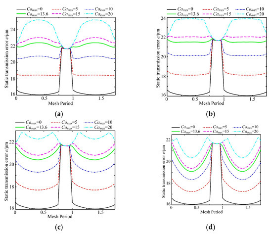
Figure 8.
Static transmission error with modification amounts: (a) β = 1; (b) β = 1.2; (c) β = 1.5; (d) β = 2.0.
The convexity and concavity of the static transmission error are different under different modification values. Because prolonged meshing is not considered, the static transmission error of a single-tooth meshing zone is nearly the same under different modification curves. With the increase in the maximum modification Camax, the static transmission error in the double-tooth meshing region gradually increases. If Camax increases to a certain extent, the static transmission error in the double-tooth meshing region is equal to or even exceeds the static transmission error in the single-tooth meshing region. In the case of β = 1, the static transmission error curve basically presents an upward convex trend in the meshing zone of the double tooth, and the upward convex trend becomes more obvious with the increase in the amount of modification. However, the static transmission error shows a downward trend in the cases of β = 1.5 and 2. The static transmission error curve is basically horizontal in the whole gear meshing cycle with β = 1.2 and Camax = 13.6 μm, which can cause the gear to drive more smoothly.
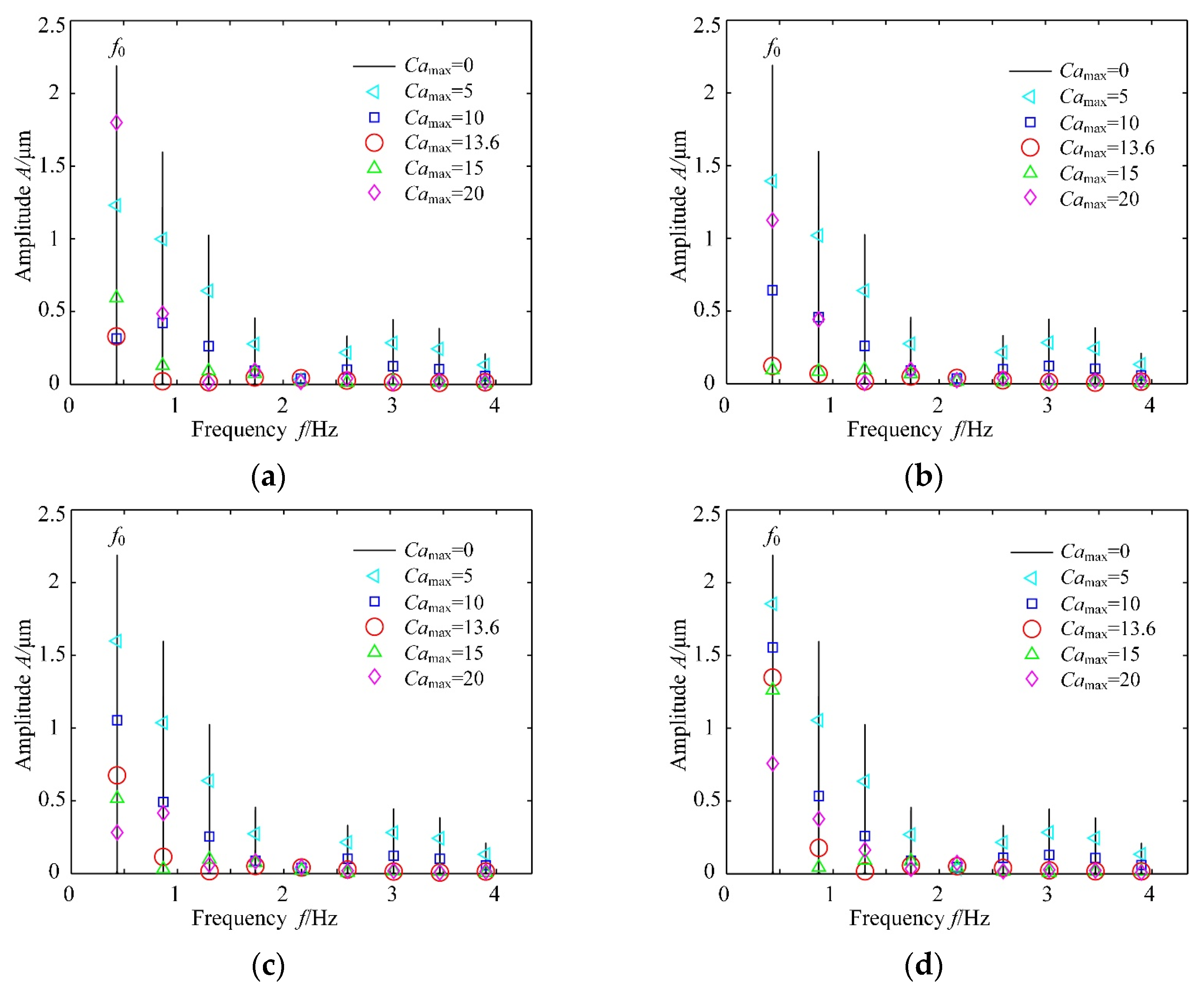
The frequency characteristics of the static transmission error curve with different Camax and β values are investigated, as shown in Figure 9. With increasing Camax, the amplitude of the transmission error first decreases and then increases. The amplitude reaches the minimum value in the case of Camax = 13.6 μm. The smaller β is, the more sensitive the amplitude A is to the change in Camax. The first four frequencies of the static transmission error spectrum are the smallest in the case of β = 1.2 and Camax = 13.6 μm. These parameters have the best effect.
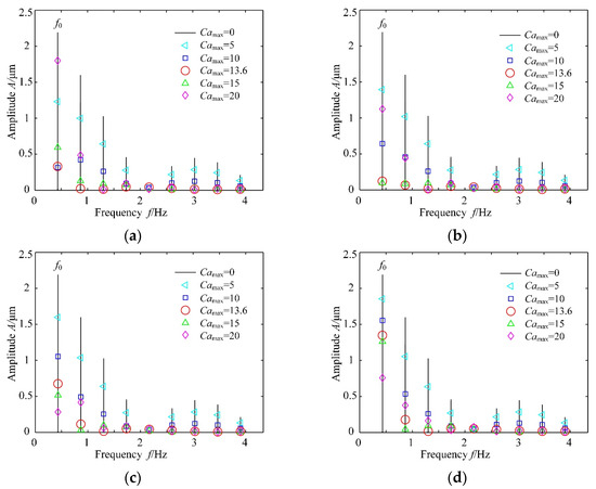
Figure 9.
Spectrum of the static transmission error: (a) β = 1; (b) β = 1.2; (c) β = 1.5; (d) β = 2.0.
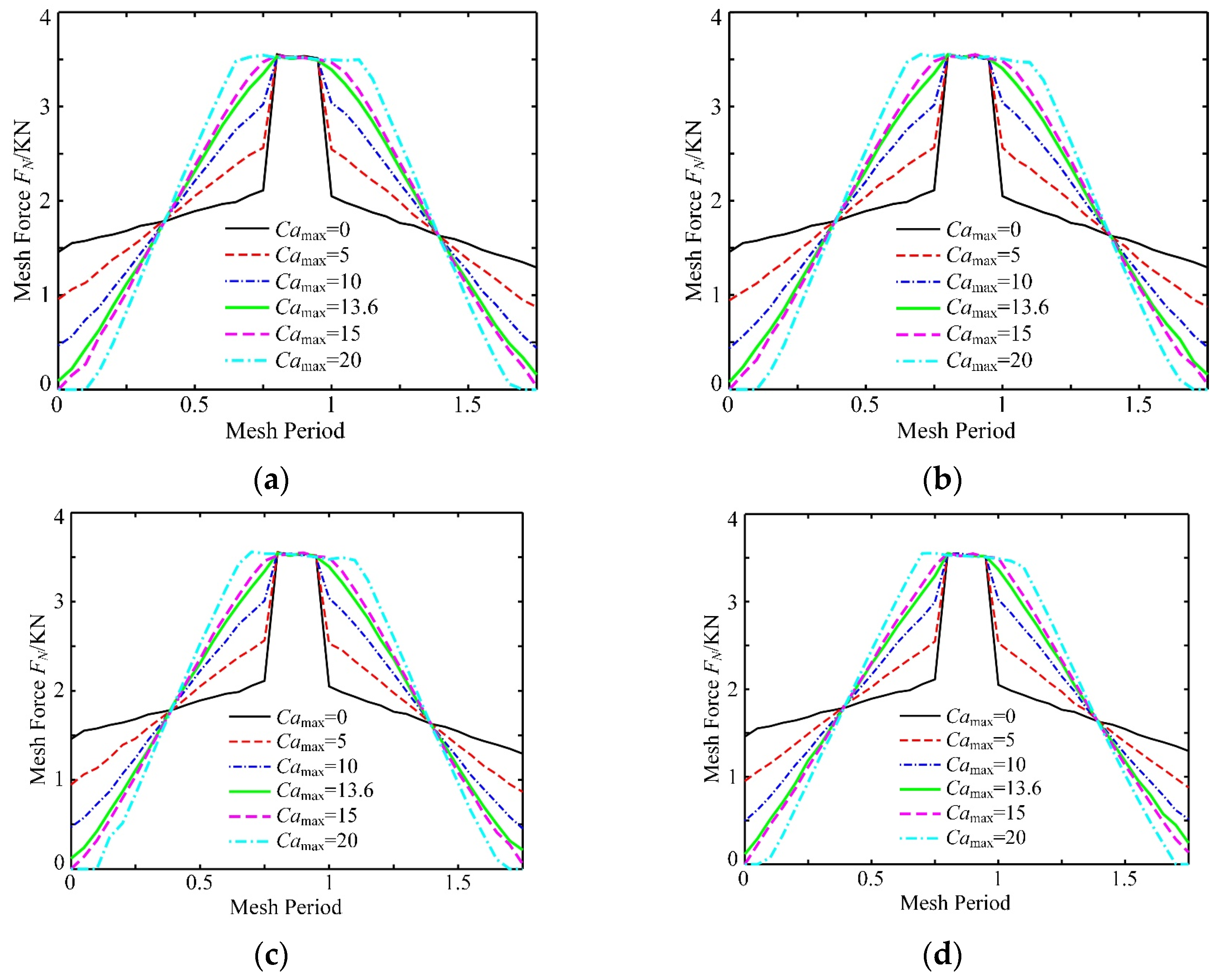
The meshing process of a single tooth is investigated, as shown in Figure 10, with different Camax and β values. Single and double teeth are engaged alternately, from double-tooth meshing to single-tooth meshing and then to double-tooth meshing. A high mesh force FN is generated in the single-tooth meshing. There is an abrupt change between single-tooth meshing and double-tooth meshing under the condition of Camax = 0. However, the modified gear can reduce the abrupt change in the mesh force FN. Additionally, a suitable parameter β can smooth the turning point in the transmission process of the modified gear.
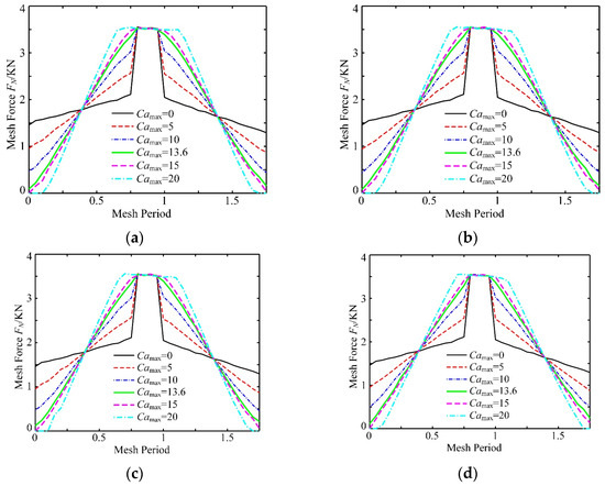
Figure 10.
Load curve of a single tooth with different maximum modification amounts: (a) β = 1; (b) β = 1.2; (c) β = 1.5; (d) β = 2.0.
The influences of the parameters are investigated depending on the modified gear system. Based on Equation (1), Camax = 13.6 μm and β = 1.2 are recommended to improve the static transmission error.
5. Influences of the Modification Gear on the Transmission Error
5.1. Effect of the Load
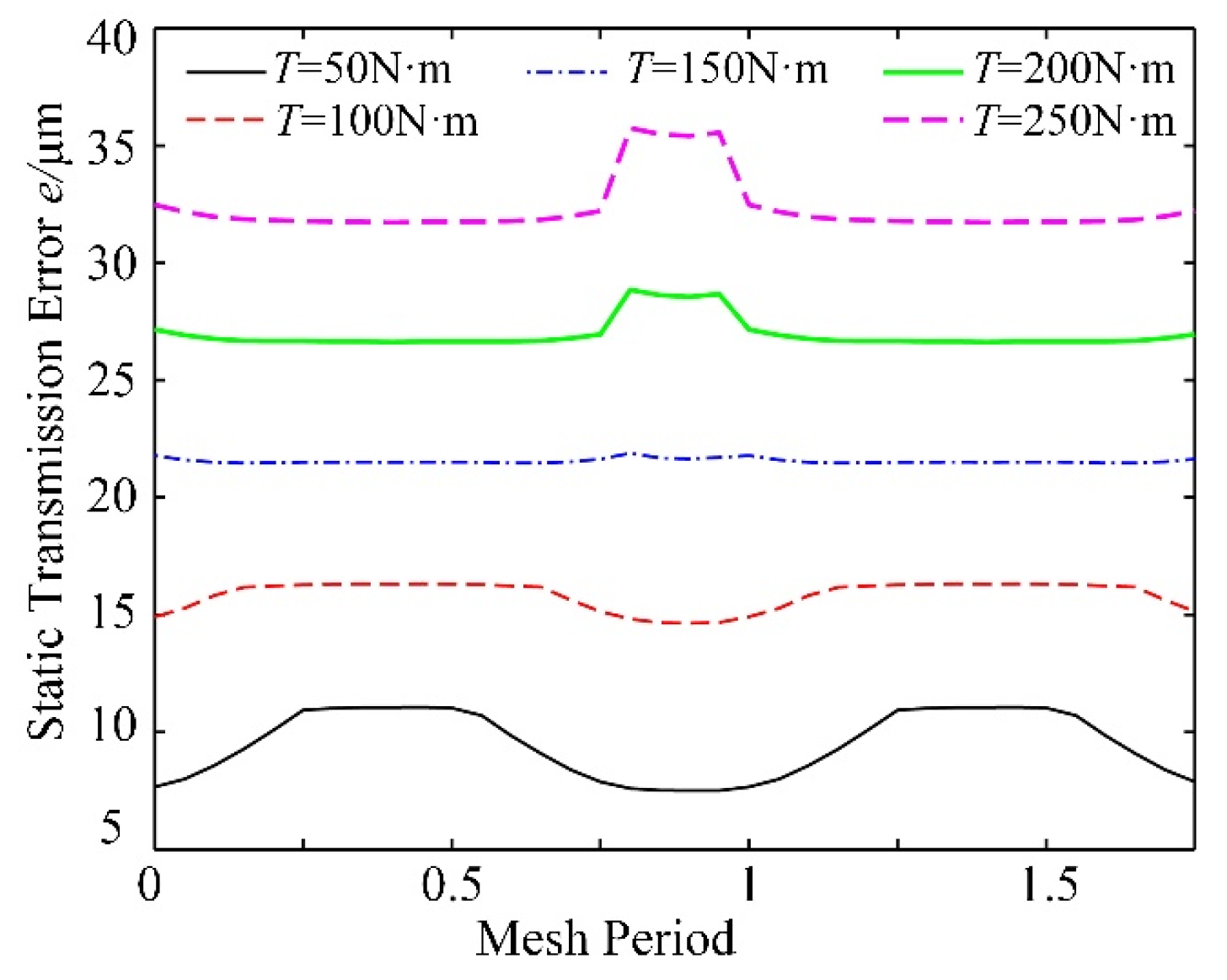
Structural parameters and load parameters are investigated to analyze the transmission error of the modified gear on the condition of Camax = 13.6 μm and β = 1.2. Considering different load torques T, the static transmission error is investigated, as shown in Figure 11. In the case of T < 150 N·m, the static transmission error is increased during double-tooth meshing. However, the error is decreased during double-tooth meshing in the case of T > 150 N·m. For the modified gear, different load torques can cause different changing rules of the transmission error.
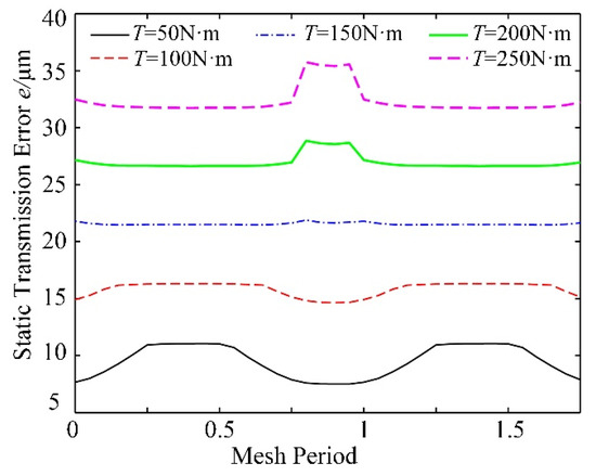
Figure 11.
Static transmission errors under different loads.
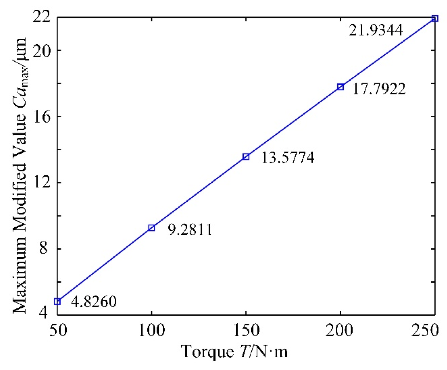
Additionally, the relation between the maximum modification value and load torque is expressed as shown in Figure 12. The maximum modified value is almost linear to the load torque, which can be utilized to determine the modified value on the condition of different torques.
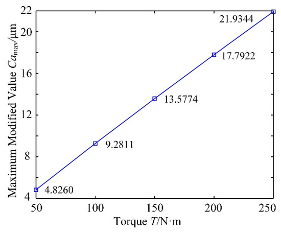
Figure 12.
Maximum modification values under loads.
5.2. Effect of Prolonged Meshing
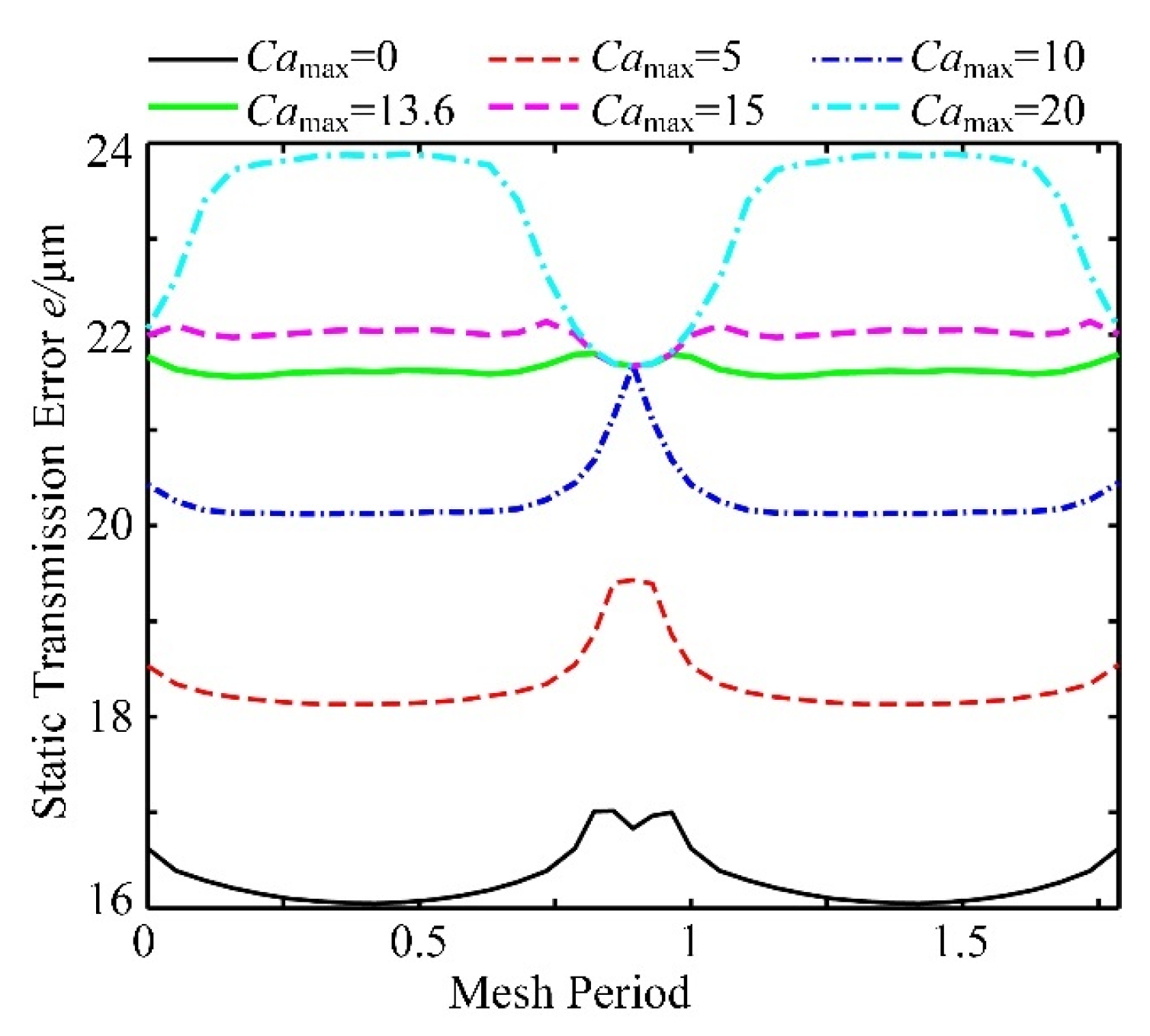
Prolonged meshing is due to the elastic deformation of the gear tooth under the load torque, which makes the last pair of gear teeth enter meshing in advance before the theoretical meshing point. Prolonged meshing is impacted by the modification value and load. Considering different cases of Camax and β = 1.2, the static transmission error is calculated to present the performance of gear teeth in Figure 13.
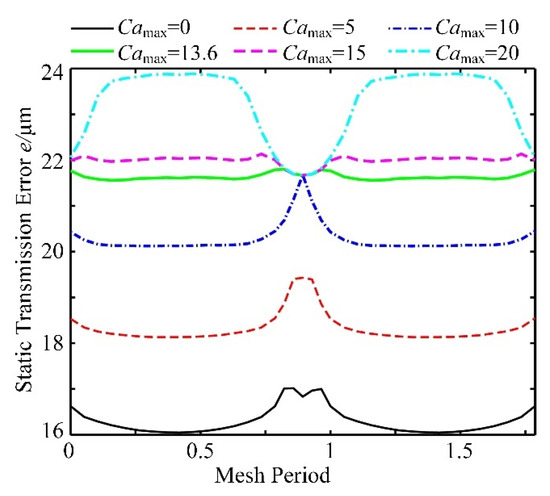
Figure 13.
Static transmission error with prolonged meshing.
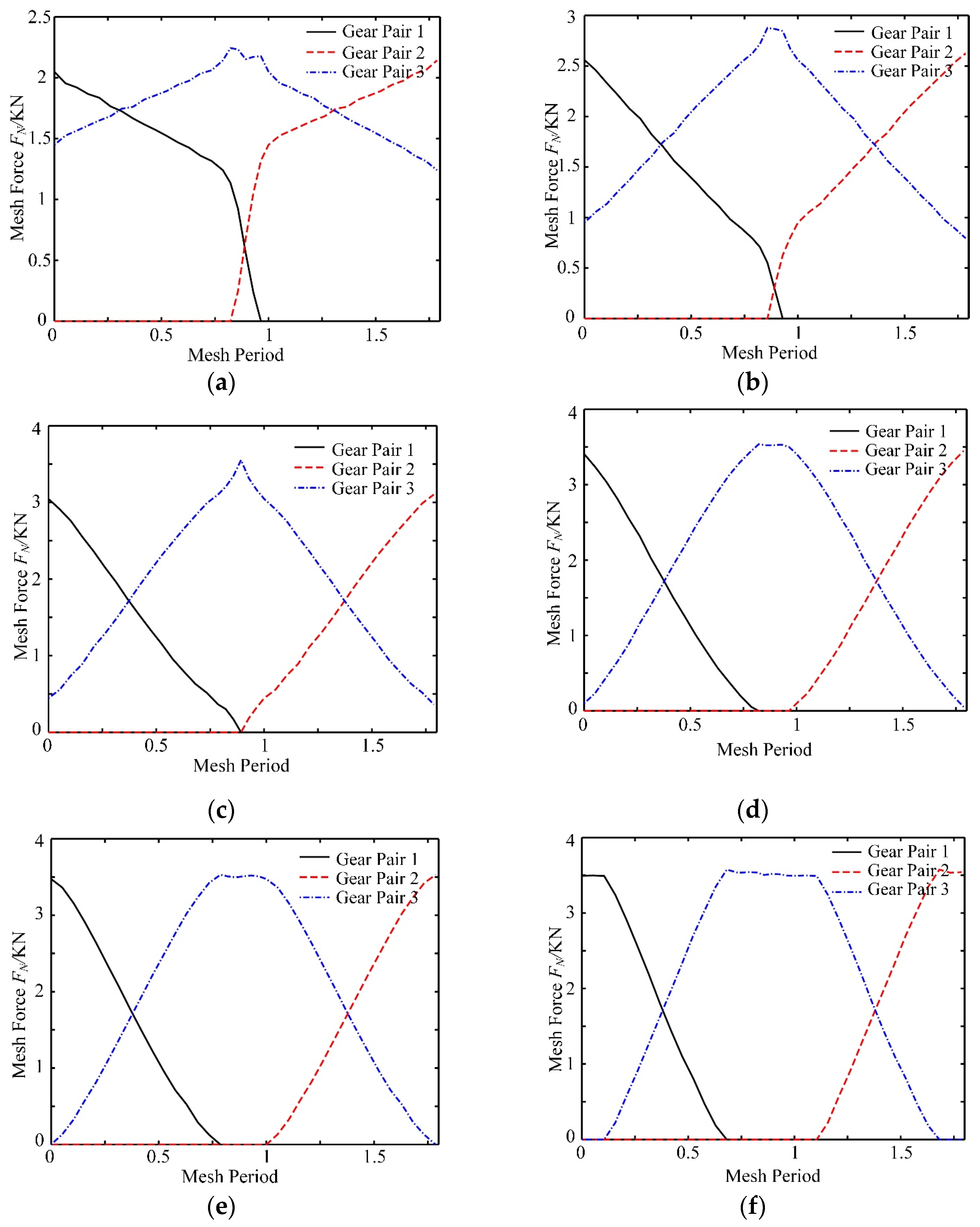
In the case of Camax < 13.6 μm, double- or even triple-tooth meshing occurs, which is caused by prolonged meshing. The early meshing and delayed meshing of different gear teeth can appear in Camax = 0. Additionally, the error is approximately stable in the case of Camax = 13.6 μm, which is beneficial for the gear transmission. The results of the meshing process are listed in Figure 14 with different modification values of Camax. A suitable modification value can prevent the performance of triple-gear-tooth meshing from decreasing the fluctuation of the mesh force.
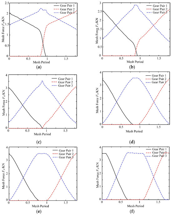
Figure 14.
Load curves considering extended tooth contact: (a) Camax = 0; (b) Camax = 5 μm; (c) Camax = 10 μm; (d) Camax = 13.6 μm; (e) Camax = 15 μm; (f) Camax = 20 μm.
5.3. Effect of the Gear Hole Radii
In engineering, gears with the same basic parameters may be matched with different shafts that have different diameters. The radius of the gear hole also changes accordingly. Different radii of the gear hole can change the stiffness of the gear body and then affect the elastic deformation of the gear pair under load. Additionally, the gear transmission error is directly related to the elastic deformation of the gear body. Considering different radii of the gear holes rh1 and rh2, the relationship between the static transmission error and modification values, Camax = 13.6 μm and β = 1.2, are analyzed, as shown in Figure 15.
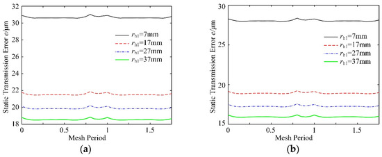
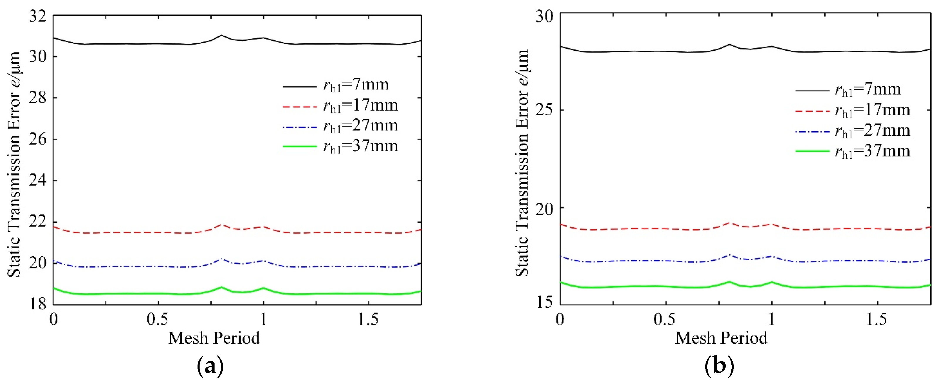
Figure 15.
Static transmission error with different gear hole radii, (a) rh2 = 20 mm; (b) rh2 = 40 mm.
The static transmission error under different gear hole radii basically does not change, except for a slight fluctuation in the alternating position of single and double teeth. This is because the aim of the modification is mainly to eliminate the interference caused by the elastic deformation of gear teeth, which can reduce and eliminate the impact of meshing in and meshing out. However, the change in the hole radius does not affect the elastic deformation of gear teeth or the interference value of gear teeth. The static transmission error decreases with the increasing radius of the gear hole, and the change rate of the gear with the small hole is larger than that of the large hole. If the gear basic parameters are determined, only the fluctuation degree of the static transmission error curve is considered in the modification design. However, the effects of the radius of the gear hole can be ignored.
6. A Two-Stage Profile Modification Curve
The modified parameters, Camax = 13.6 μm and β = 1.2, can reduce the mean value and fluctuation of the static transmission error. However, the fluctuation cannot be ignored in Figure 16, such as in AC and BD. The optimization design of the profile modification curve should be investigated to decrease the fluctuation.
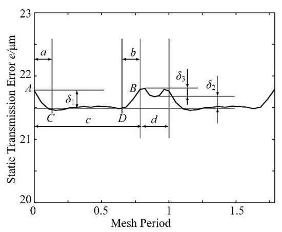
Figure 16.
Fluctuation of the static transmission error curve.
Parameters δ1, δ2, and δ3 can be optimized for the static transmission error in Figure 16. Parameter δ3 is utilized to depict the meshing process of the single gear tooth, which causes an increase in the transmission error. Prolonged meshing can increase the double-tooth meshing and mesh stiffness. The transmission error can be decreased. Hence, a suitable Parameter Camax can generate prolonged meshing with a stable transmission error. According to Section 4, Parameters Camax and β can decrease the values a and b and Parameters δ1 and δ2 in Figure 16. A suitable modification curve can increase the mesh stiffness and decrease the static transmission error. Point D is taken as a changing point. The modification curve is divided into two curves. Parameter β of the modified curve near the top of the tooth is changed from 1.2 to 1. An optimized modification curve is proposed as follows:
where α = 0.9 and γ = 0.07. The other parameters are the same as those in Equation (1). Considering Camax = 13.6 μm, the effects of Equation (1) and Equation (8) are compared. The gears before and after optimization are investigated, as shown in Figure 17.
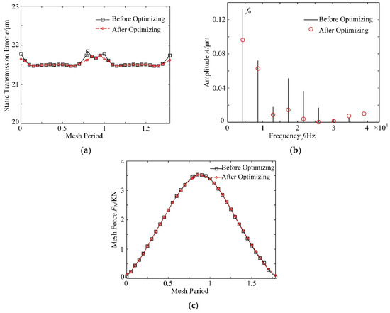
Figure 17.
Results comparison before and after optimization, (a) static transmission error; (b) amplitude; (c) mesh force.
Parameters δ1, δ2, and δ3 decrease between the single-tooth meshing and double-tooth meshing in Figure 17a. Moreover, the difference between the maximum transmission error and the minimum transmission error decreases from 0.3760 to 0.2721, and it can be defined as ep. The peak value and the range of fluctuation of the static transmission error are both reduced. Additionally, the amplitude of each frequency and the maximum mesh force are decreased in Figure 17b,c, respectively. The optimized profile modification curve in Equation (8) can reduce the static transmission error and improve the meshing process of the gear transmission. Moreover, Equation (8) is utilized to modify different gears, as shown in Table 1, to evaluate the effects. The different gears with different parameters in Table 1 are considered to verify the applicability of the proposed curve of Equation (8). The results are listed in Table 2.

Table 1.
Parameters of the gears.
Table 2.
Static transmission error of the peak-to-peak value.
In Table 1, Parameter ep is utilized to evaluate the modification effect. The modified gear can decrease the transmission error by at least 20.7%. The difference between the maximum transmission error and the minimum transmission error can be reduced, which is beneficial for the transmission process.
Hence, the optimized modification curve in Equation (8), which is a two-stage curve, can be utilized to modify the driving and driven gears. Additionally, the mesh force and static transmission error can be reduced in modified gears.
7. Dynamic Analysis of the Modified Gear System
7.1. Dynamic Responses of the Modified Gear System
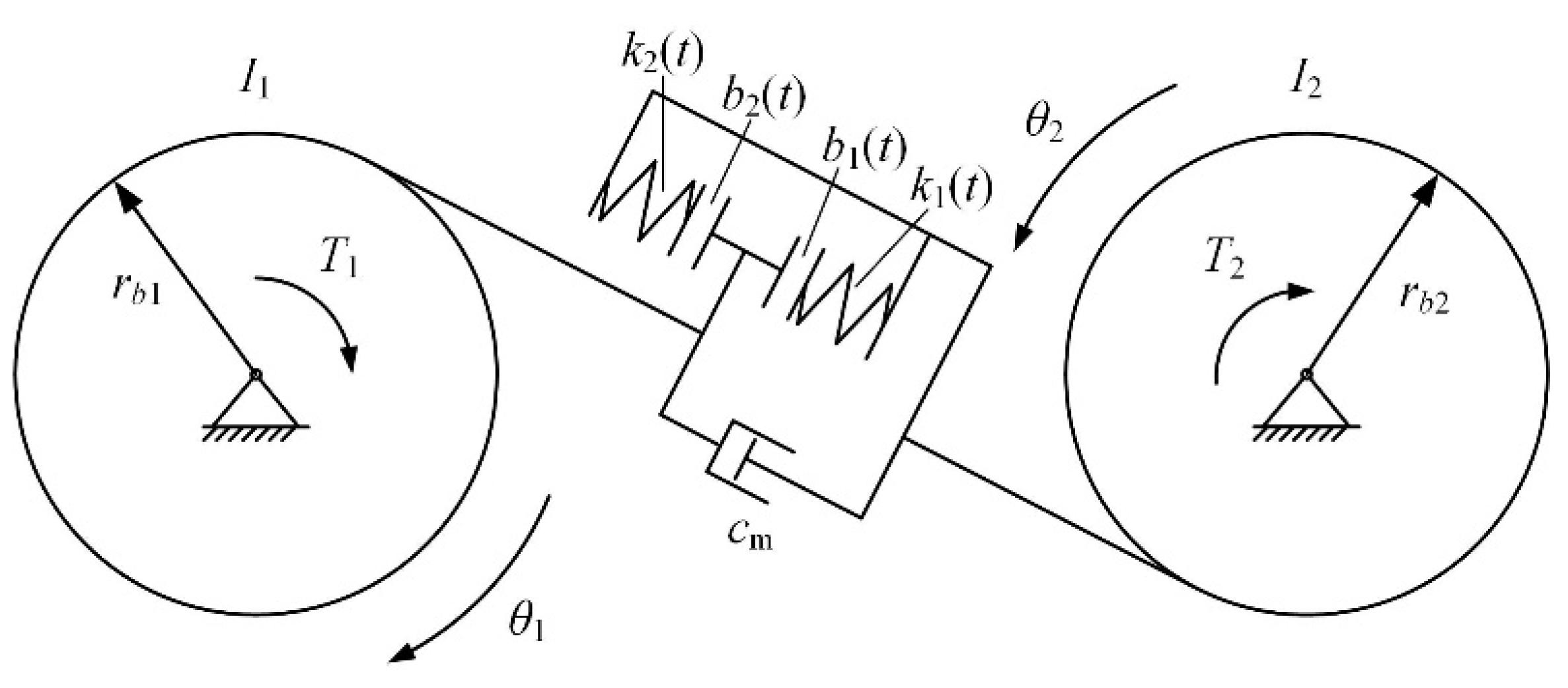
The dynamic performance of the gear transmission system is investigated to determine the influence of the modified gear. Because of the modification value, the mesh stiffness k(t) and time-varying backlash b(t) are different from those of the standard gears. The dynamic model of the modified gear drive is established as shown in Figure 18. Parameters k1(t), b1(t) and k2(t), b2(t) are influenced by the modification value, which is considered as different values in forward and backward gear meshing [36].

Figure 18.
Dynamic model of the modified gear drive.
Additionally, the dynamic equation can be expressed as follows:
In which Ii, Ti, k(t), cm, θi, and rbi (i = 1, 2) represent the moment of inertia, torque, mesh stiffness, mesh damping, torsional displacement, and base radius of the modified gear, respectively, as shown in Figure 18. The dynamic transmission error can be expressed as . In Figure 18, the nonlinear backlash function can be expressed as follows:
According to Figure 6 and Equation (6), the relation between Parameter b1(θ(t)) and angle θ(t) of the driving gear can be presented by the following:
In which . In Equation (11), Parameters αst, Lst, L, ψ0, and ω represent the pressure angle at the starting point of modification, the corresponding radius AE in Figure 6, the modified length DE in Figure 6, the angle of the driving gear in the double-tooth meshing, and the rotating angular speed, respectively. Backlash is influenced by forward and backward meshing. In Figure 19, the solid profile and the dashed profile represent the forward meshing position of the driven gear and the exit position of backward meshing.
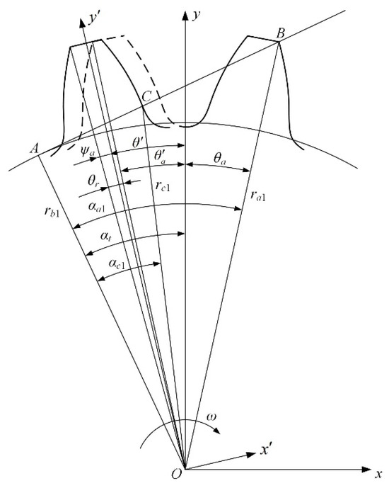
Figure 19.
Forward and backward meshing process.
According to Figure 19, the relation of angles can be expressed as follows:
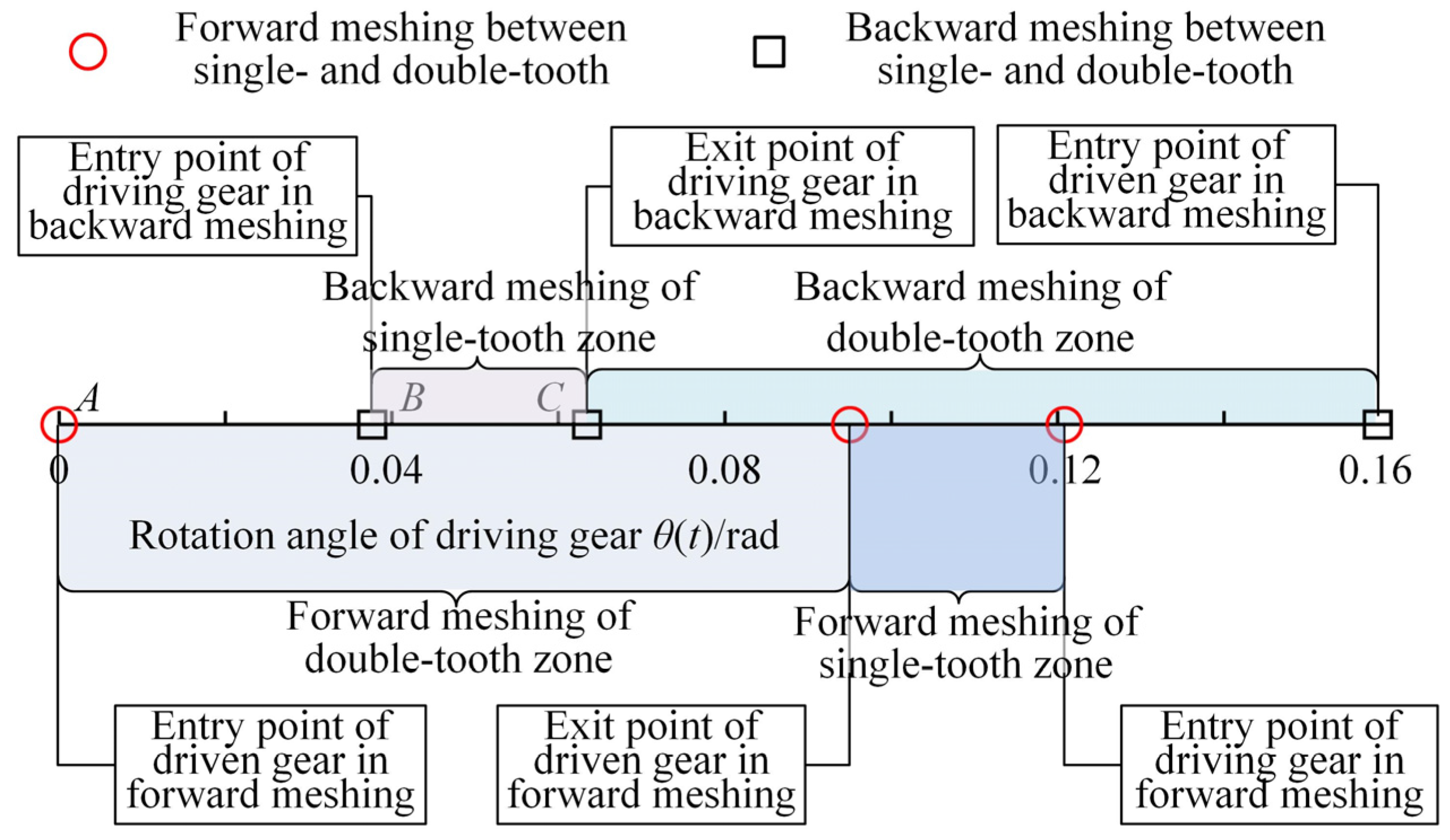
where and . The nonlinear backlash, b1(t) and b2(t), can be depicted for the meshing process. Additionally, the meshing process can be divided into different sections to depict the forward and backward meshing in Figure 20.
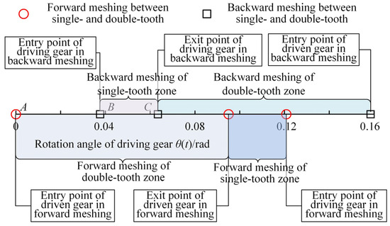
Figure 20.
Transition location of single- and double-tooth meshing.
Based on Figure 7, the time-varying stiffness of forward meshing is depicted as k1(θ(t)), and the corresponding stiffness of backward meshing can be expressed as follows:
In contrast to standard gears, modified gears can lead to different backlash and mesh stiffnesses, which directly influence the dynamic transmission process. The algorithm of dynamic transmission error of modified gear is listed in Algorithm 2.
| Algorithm 2: Dynamic transmission error for the modified gear by the dynamic model | ||
| Input: Number of teeth z, Modulus m, Load T, Base radius rb, Moment of inertia I. Output: Dynamic transmission error e. | ||
| 1: | Establish the nonlinear backlash function by (10). | |
| 2: | For Camax = 0, 5,…,20 do | |
| 3: | Establish the relationship between backlash and angle by (11). | |
| 4: | Depict the transition location of single and double-teeth meshing by Figure 20 in the dynamic model. | |
| 5: | Mesh stiffness can be calculated by (12) and (13). | |
| 6: | Calculate the dynamic equation of gear pair by (9). | |
| 7: | Compute θ1 and θ2. Dynamic transmission error can be calculated by {rb1θ1–rb2θ2} based on Figure 18. | |
| 6: | End | |
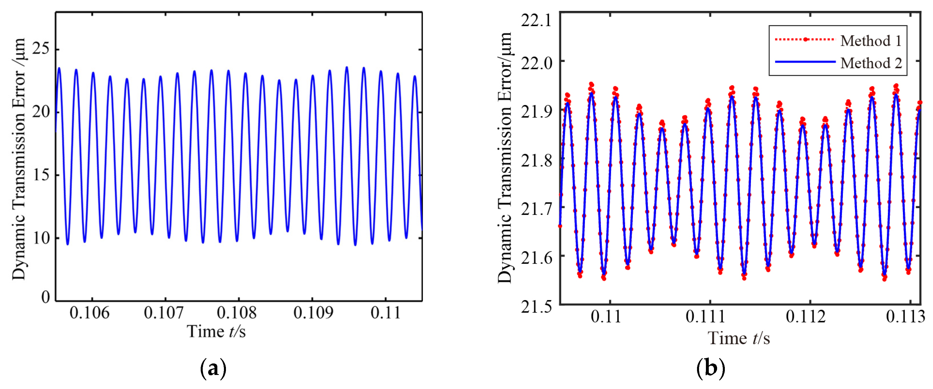
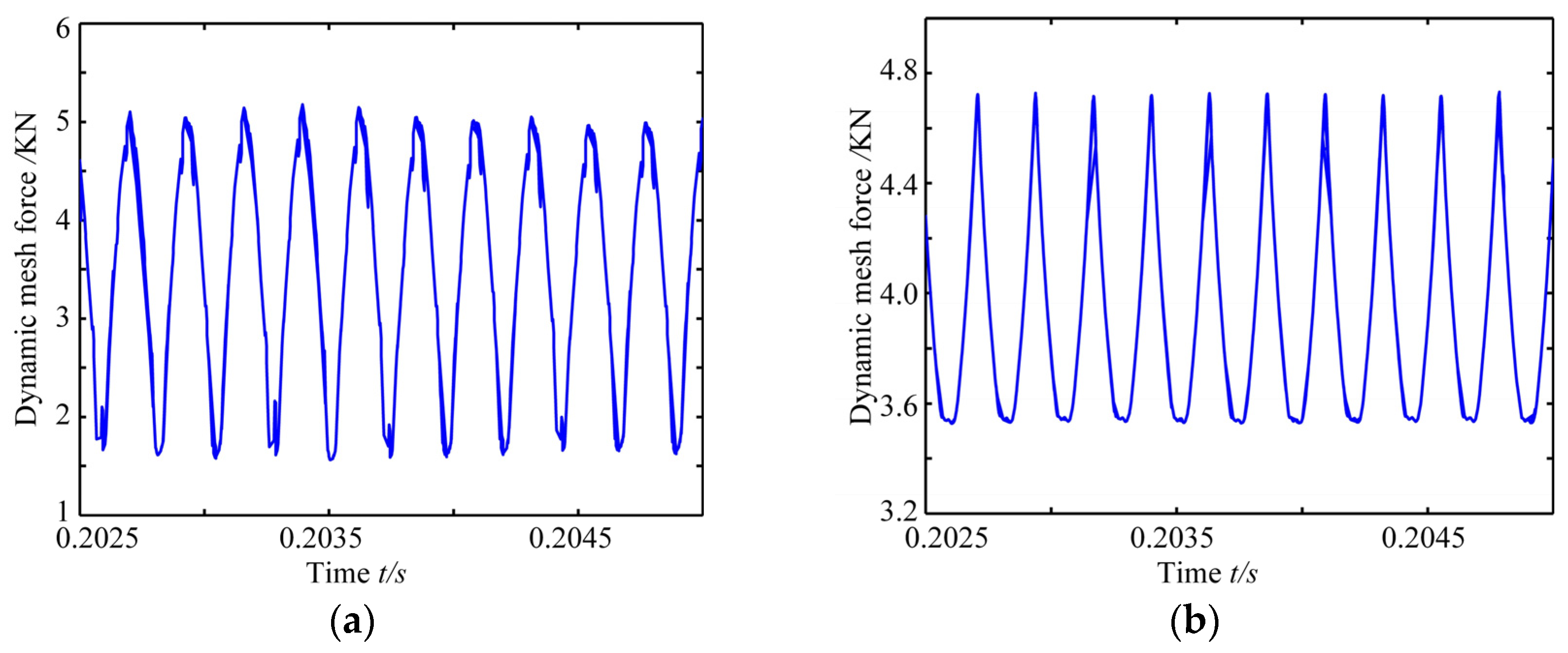
Considering Team C in Table 1 and n = 5000 r/min, the dynamic transmission error is investigated with regard to the modified gears with the proposed method. In Figure 21, the dynamic transmission error decreases rapidly and reaches the steady state, which is shown in Figure 22. The negative value in Figure 21a indicates backward meshing, which can be eliminated by the modified gears. Compared to Figure 22a,b, the mean values are close to each other. However, the modified gear can decrease the range of the dynamic transmission error in Figure 22. Also, the dynamic performance of the proposed modified method in Equation (8) is better than the modified method in Equation (1). The amplitude of the transmission error can also be reduced by the proposed modified method in Figure 23. Also, the mesh force can be decreased, as shown as Figure 24.
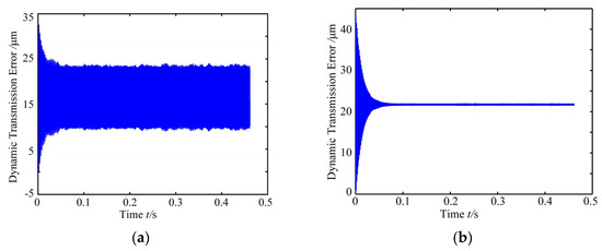
Figure 21.
Dynamic transmission error in the time domain: (a) standard gear; (b) modified gear.

Figure 22.
Stable state of the dynamic transmission error in the time domain: (a) standard gear; (b) modified gear, method 1: modified by Equation (1), method 2: modified by Equation (8).
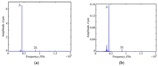
Figure 23.
Stable state of the dynamic transmission error in the time domain: (a) standard gear; (b) modified gear by Equation (8).
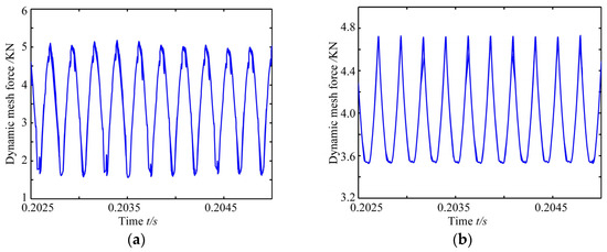
Figure 24.
Stable state of dynamic mesh force: (a) standard gear; (b) modified gear by Equation (8).
The root mean square value of the acceleration of the dynamic transmission error can be utilized to evaluate the intensity of the vibration and noise, which can be expressed as follows:
where N and are the number of samples and the acceleration of the dynamic transmission error, respectively. The values of the modified gear and standard gear are 76.375 m/s−2 and 3321 m/s−2, respectively. Hence, the modification technique can lower the meshing noise of the gear system.
7.2. Parametric Effects on the Dynamic Responses
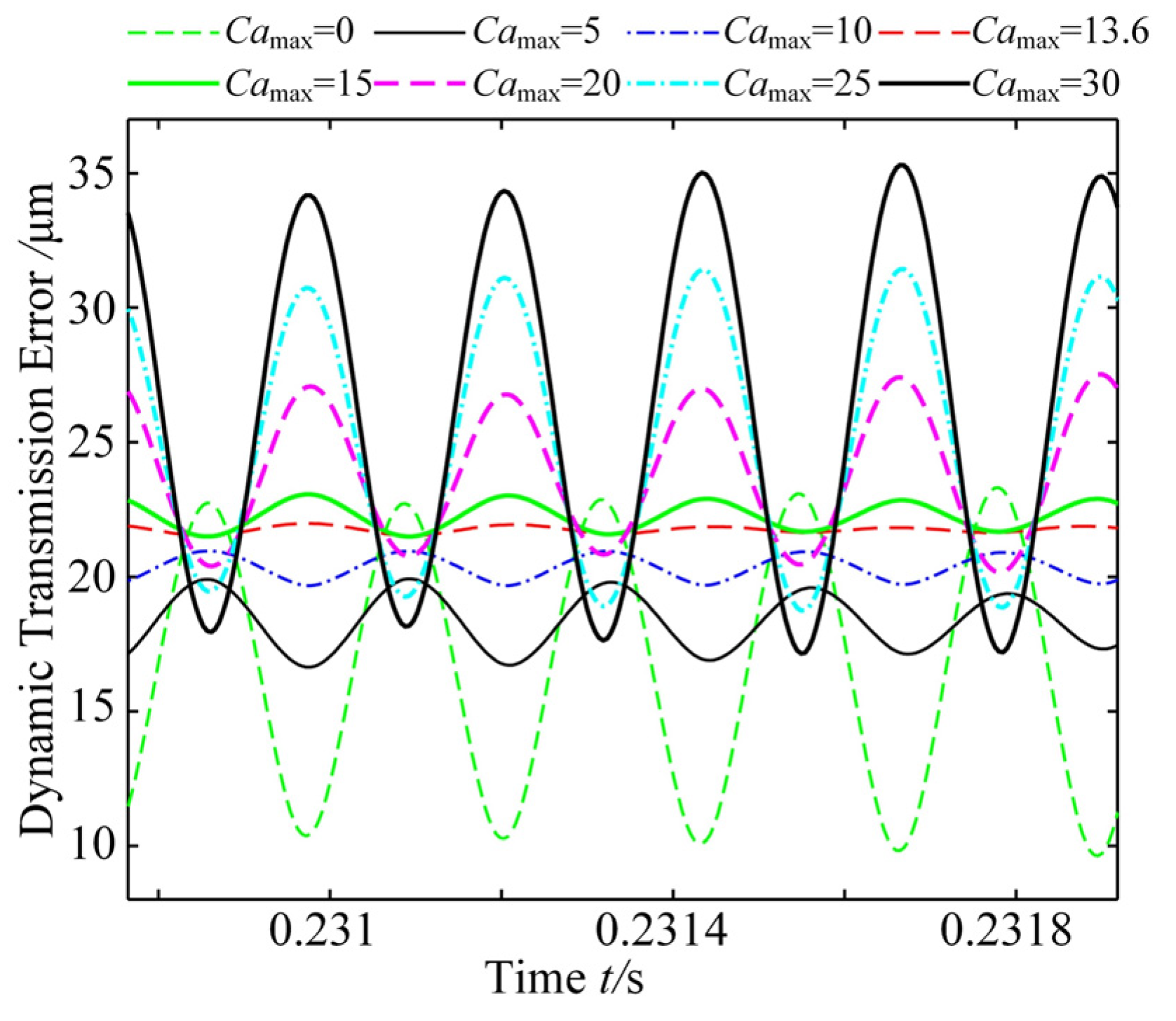
According to the dynamic model of the modified gear, the dynamic transmission error is investigated under the condition of different modification values of Camax. Considering Camax = 13.6, a good effect can be achieved to reduce the dynamic transmission error, as shown in Figure 25. Additionally, the root mean square of acceleration can be decreased, which reduces the influence of noise, as shown in Figure 26.
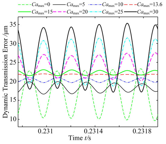
Figure 25.
Dynamic transmission error with different Camax values.
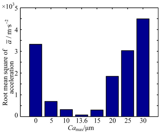
Figure 26.
Acceleration with different Camax values.
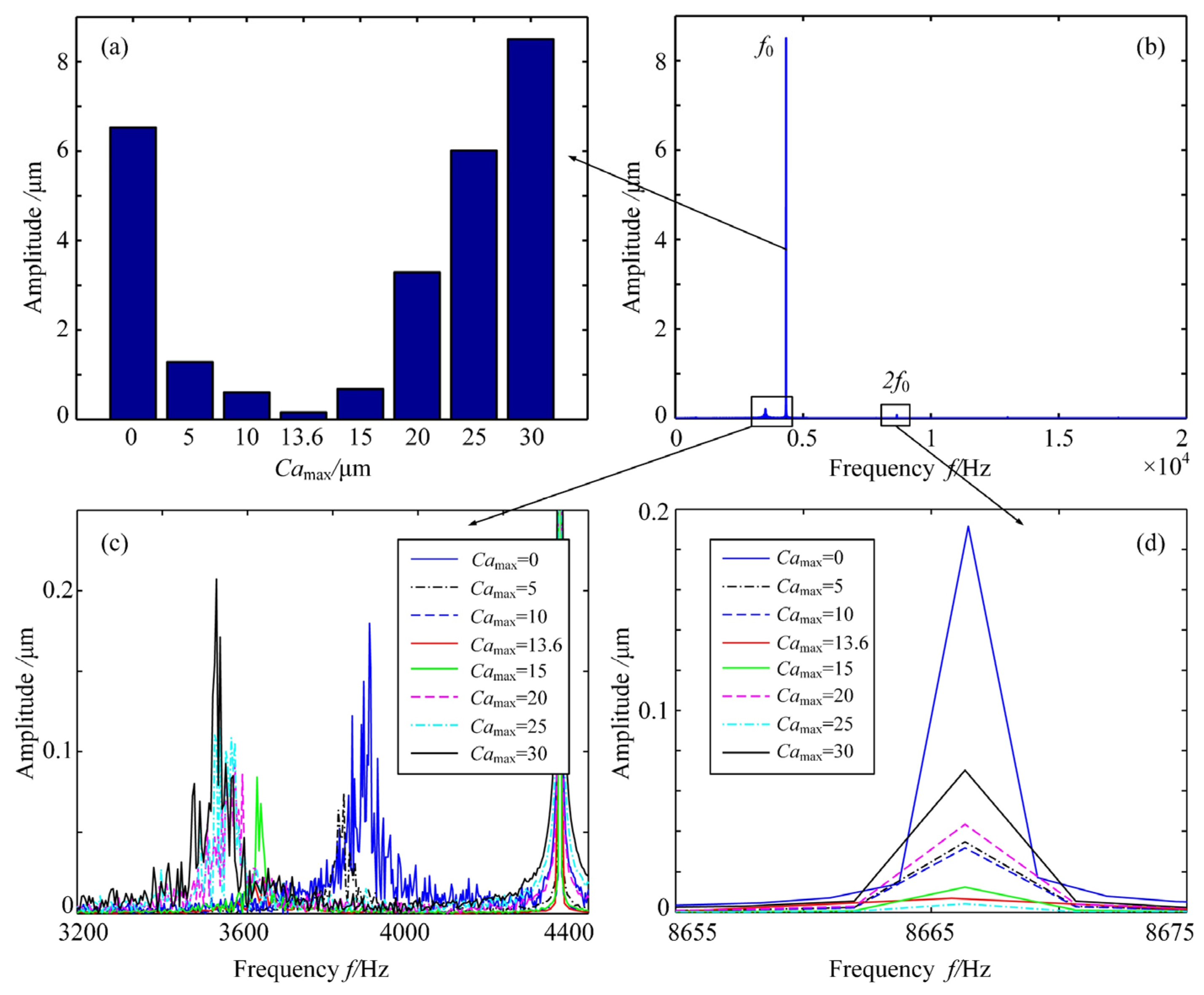
The spectrum of the dynamic transmission error with different Camax values is expressed as shown in Figure 27. The whole frequency of the transmission error is presented in Figure 27b. Camax = 13.6 can reduce the amplitude of the main frequency f0, as shown in Figure 27a. The amplitudes of other frequencies are expressed in Figure 27c,d. With increasing Camax, the amplitude of the dynamic transmission error first decreases and subsequently increases.
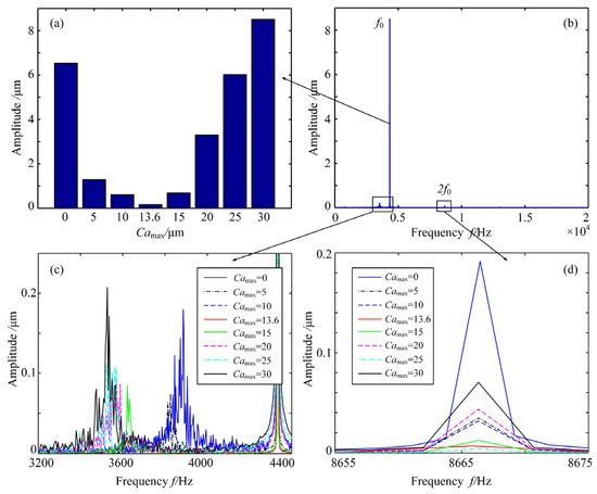
Figure 27.
Spectrum of the dynamic transmission error with different Camax values: (a) Amplitude of f0 with different Camax; (b) Spectrum of transmission error; (c) Amplitude from 3200 Hz to 4400 Hz; (d) Amplitude from 8655 Hz to 8675 Hz with different Camax values.
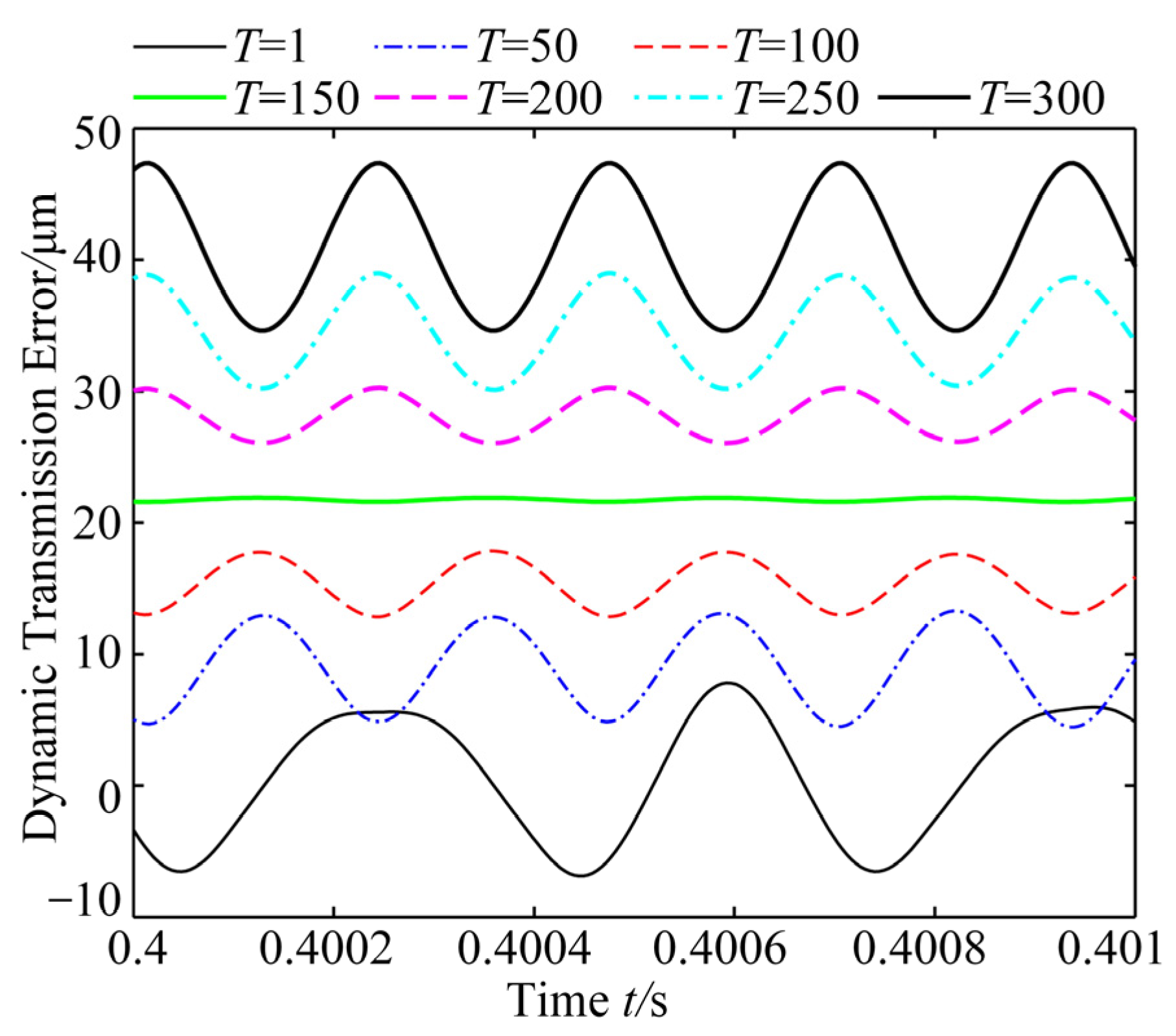
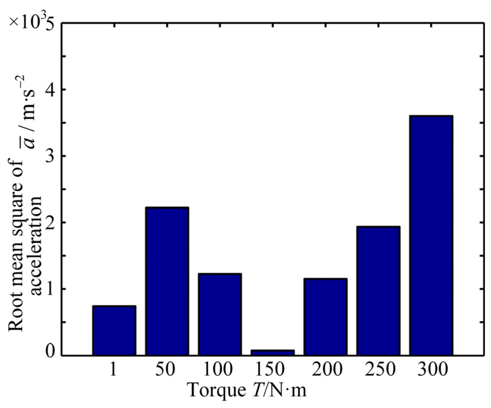
The relation between the torque T and dynamic transmission error is investigated in Figure 28. The suitable torque, T = 150 N·m, can reduce the root mean square of acceleration, as shown in Figure 29. Lower and higher torques can cause higher dynamic transmission errors, which are influenced by backward and forward meshing between single and double teeth. Hence, the suitable torque needs to be found for smooth meshing.
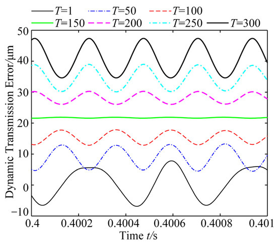
Figure 28.
Dynamic transmission error.

Figure 29.
Acceleration with different T values.
The spectrum of the dynamic transmission error with different T values is expressed as shown in Figure 30.
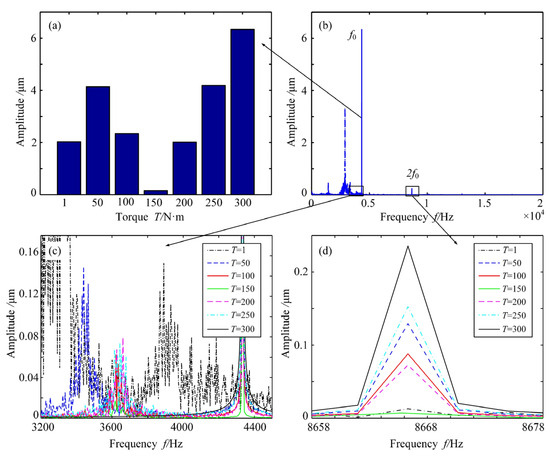
Figure 30.
Spectrum of the dynamic transmission error with different T values. (a) Amplitude of f0 with different T values; (b) Spectrum of dynamic transmission error; (c) Amplitude from 3200 Hz to 4400 Hz; (d) Amplitude from 8658 Hz to 8678 Hz with different T values.
The whole frequency of transmission error is presented in Figure 30b. With increasing T, the amplitude of the dynamic transmission error first decreases and subsequently increases. Hence, a suitable modification value and torque can reduce the meshing noise and the transmission error. Considering forward meshing and backward meshing, a dynamic model with backlash and time-varying stiffness is investigated to depict the dynamic performance of the modified gear. Additionally, the influences of Parameters Camax and T are investigated to present the relationship between each parameter and the transmission error.
8. Conclusions
The modification technique can improve the transmission characteristics of any gear system, which reduces the static transmission error and dynamic transmission error. The parametric model of the modified gear is set up. The influences of the load, radius of the gear hole and prolonged meshing on the static transmission error are investigated. The radius of the gear hole only affects the overall level of static transmission error but does not affect its fluctuation. Depending on the maximum interference value, the modification values, β = 1.2 and Camax = 13.6 μm, can be defined to avoid prolonged meshing.
Based on the calculated values β = 1.2 and Camax = 13.6 μm, a two-stage modification curve is proposed to optimize the gear pair. The range and amplitude of the static transmission error is decreased, which can improve the performance of the spur gear system. Moreover, a dynamic transmission model is analyzed for the dynamic characteristics, considering the time-varying stiffness and backlash of the modified gear. The proposed modification curve can decrease the vibration displacement and noise. Additionally, the amplitudes of different frequencies can be reduced, which is beneficial for dynamic transmission. Considering different working conditions, both static transmission error and dynamic transmission error are considered to evaluate the proposed modified method, which can be utilized for spur gear drives. The avoidance of the interference of the modified gear and the use of a modified method for dynamic transmission errors can be investigated in the future.
Author Contributions
Conceptualization and methodology, D.Z. and Y.G.; software and validation, D.Z., J.Y. and Y.G.; formal analysis and resources, J.Y. and Y.Z.; writing—original draft preparation, D.Z.; writing—review and editing, D.Z. and Y.G.; visualization, J.Y.; supervision, Y.Z. All authors have read and agreed to the published version of the manuscript.
Funding
This project is supported by the Foundation of Key Laboratory of Vibration and Control of Aero-Propulsion System, Ministry of Education (VCAME202104), which received support from Northeastern University. Also, the project is supported by the Fundamental Research Funds for the Central Universities (2232023D-17) and the National Natural Science Foundation of China (Grant No. 52005327).
Data Availability Statement
Data are contained within the article.
Acknowledgments
Thank you for the reviewers’ comments and the editors’ works.
Conflicts of Interest
Jian Yang was employed by the company Volkswagen (Anhui) Co., Ltd. The remaining authors declare that the research was conducted in the absence of any commercial or financial relationships that could be construed as a potential conflict of interest.
Nomenclature
| z | Number of teeth |
| r | Reference circle |
| ra | Radius of the addendum circle |
| rb | Base radius of the unmodified involute curve |
| rc | Radius of the starting point in the modified involute curve |
| Base radius of the unmodified involute curve | |
| cm | Mesh damping |
| θi | Torsional displacement |
| αa | Pressure angle of the unmodified involute curve |
| αc | Pressure angle of the modified involute curve |
| Pressure angle of the starting point in the modified involute curve | |
| Pressure angle of the tip circle in the modified gear | |
| β | Modified index |
| δin | Maximum interference value along the line of engagement |
| k(t) | Mesh stiffness |
| L | Relative coordinate of the modified length |
| Ii | Moment of inertia of Gear i |
| Ti | Torque of Gear i |
| Camax | Maximum modified value |
| Ca | Modified value corresponding to Position x |
References
- Wang, C. Multi-objective optimal design of modification for helical gear. Mech. Syst. Signal Process. 2021, 157, 107762. [Google Scholar] [CrossRef]
- Hu, Z.; Tang, J.; Zhong, J.; Chen, S.; Yan, H. Effects of tooth profile modification on dynamic responses of a high speed gear-rotor-bearing system. Mech. Syst. Signal Process. 2016, 76–77, 294–318. [Google Scholar] [CrossRef]
- Xie, C.; Shu, X. A new mesh stiffness model for modified spur gears with coupling tooth and body flexibility effects. Appl. Math. Model. 2021, 91, 1194–1210. [Google Scholar] [CrossRef]
- Chen, M.; Xiong, X.; Zhuang, W. Design and simulation of meshing performance of modified straight bevel gears. Metals 2021, 11, 33. [Google Scholar] [CrossRef]
- Wang, J.; Lv, H. Modification and optimization of cycloidal gear tooth profile based on machining error compensation. Appl. Sci. 2023, 13, 2581. [Google Scholar] [CrossRef]
- Wang, Q.B.; Xu, K.; Huai, T.; Ma, H.; Wang, K. A mesh stiffness method using slice coupling for spur gear pairs with misalignment and lead crown relief. Appl. Math. Model. 2020, 90, 845–861. [Google Scholar] [CrossRef]
- Bahk, C.; Parker, R.G. Analytical investigation of tooth profile modification effects on planetary gear dynamics. Mech. Mach. Theory 2013, 70, 298–319. [Google Scholar] [CrossRef]
- Liu, S.; Chen, X.; Song, C.; Zhu, C.; Bai, H.; Alfonso, F.A. Influence of gear-shaft interference fit assembly on the meshing characteristics of cylindrical gears considering comprehensive modifications. Mech. Mach. Theory 2023, 182, 105247. [Google Scholar] [CrossRef]
- Wu, Y.; Wang, J.; Han, Q. Static/dynamic contact FEA and experimental study for tooth profile modification of helical gears. J. Mech. Sci. Technol. 2012, 26, 1409–1417. [Google Scholar] [CrossRef]
- Abruzzo, M.; Beghini, M.; Santus, C.; Presicce, F. A dynamic model combining the average and the local meshing stiffnesses and based on the static transmission error for spur gears with profile modification. Mech. Mach. Theory 2023, 180, 105139. [Google Scholar] [CrossRef]
- Gao, P.; Liu, H.; Yan, P.; Xie, Y.; Xiang, C.; Wang, C. Research on application of dynamic optimization modification for an involute spur gear in a fixed-shaft gear transmission system. Mech. Syst. Signal Process. 2022, 181, 109530. [Google Scholar] [CrossRef]
- Raut, A.S.; Khot, S.M.; Salunkhe, V.G. Optimization of Geometrical Features of Spur Gear Pair Teeth for Minimization of Vibration Generation. J. Vib. Eng. Technol. 2023, 12, 533–545. [Google Scholar] [CrossRef]
- Liu, C.; Fang, Z.; Wang, F. An improved model for dynamic analysis of a double-helical gear reduction unit by hybrid user-defined elements: Experimental and numerical validation. Mech. Mach. Theory 2018, 127, 95–111. [Google Scholar] [CrossRef]
- Jiang, Y.; Chen, Z.; Tong, S.; Li, S.; Tong, Z. Gear tribodynamic modeling and analysis considering tooth profile modification. Tribol. Int. 2023, 178, 108023. [Google Scholar] [CrossRef]
- Ghosh, S.S.; Chakraborty, G. On optimal tooth profile modification for reduction of vibration and noise in spur gear pairs. Mech. Mach. Theory 2016, 105, 145–163. [Google Scholar] [CrossRef]
- Hajjaj, A.Z.; Corrigan, K.; Mohammadpour, M.; Theodossiades, S. On the stability analysis of gear pairs with tooth profile modification. Mech. Mach. Theory 2022, 174, 104888. [Google Scholar] [CrossRef]
- Sun, Y.; Ma, H.; Huangfu, Y.; Chen, K.; Che, L.; Wen, B. A revised time-varying mesh stiffness model of spur gear pairs with tooth modifications. Mech. Mach. Theory 2018, 129, 261–278. [Google Scholar] [CrossRef]
- Pleguezuelos, M.; Sánchez, M.B.; Pedrero, J.I. Analytical model for meshing stiffness, load sharing, and transmission error for spur gears with profile modification under non-nominal load conditions. Appl. Math. Model. 2021, 97, 344–365. [Google Scholar] [CrossRef]
- Velex, P.; Chapron, M.; Fakhfakh, H.; Bruyère, J.; Becquerelle, S. On transmission errors and profile modifications minimising dynamic tooth loads in multi-mesh gears. J. Sound Vib. 2016, 379, 28–52. [Google Scholar] [CrossRef]
- Pedrero, J.I.; Pleguezuelos, M.; Sánchez, M.B. Analytical model for meshing stiffness, load sharing, and transmission error for helical gears with profile modification. Mech. Mach. Theory 2023, 185, 105340. [Google Scholar] [CrossRef]
- Jun, Z.; Wei-min, T.; Qin, C.; Tao, C. Reliability sensitivity analysis of tooth modification on dynamic transmission error of helical planetary gears. Proc. Inst. Mech. Eng. Part C J. Mech. Eng. Sci. 2020, 234, 3903–3918. [Google Scholar] [CrossRef]
- Sun, Z.; Tang, J.; Chen, S.; Chen, Y.; Hu, Z.; Wang, Z.; Lu, R.; Chen, X. Mesh stiffness and dynamic response analysis of modified gear system with thin web and weight reduction holes. J. Sound Vib. 2023, 546, 117437. [Google Scholar] [CrossRef]
- Tsai, M.H.; Tsai, Y.C. A method for calculating static transmission errors of plastic spur gears using FEM evaluation. Finite Elem. Anal. Des. 1997, 27, 345–357. [Google Scholar] [CrossRef]
- Park, C.I. Tooth friction force and transmission error of spur gears due to sliding friction. J. Mech. Sci. Technol. 2019, 33, 1311–1319. [Google Scholar] [CrossRef]
- Li, H.; Chen, S.; Tang, J.; Chen, W.; Ouyang, H. A novel approach for calculating no-load static transmission error based on measured discrete tooth surfaces. Mech. Mach. Theory 2019, 138, 112–123. [Google Scholar] [CrossRef]
- Yang, Y.; Cao, L.; Li, H.; Dai, Y. Nonlinear dynamic response of a spur gear pair based on the modeling of periodic mesh stiffness and static transmission error. Appl. Math. Model. 2019, 72, 444–469. [Google Scholar] [CrossRef]
- Wang, C.; Ding, P.; Huang, X.; Gao, T.; Li, C.; Zhang, C. Reliability sensitivity analysis of ball-end milling accuracy. Int. J. Adv. Manuf. Technol. 2021, 112, 2051–2064. [Google Scholar] [CrossRef]
- Benatar, M.; Handschuh, M.; Kahraman, A. Talbot Static and dynamic transmission error measurements of helical gear pairs with various tooth modifications. J. Mech. Des. 2019, 141, 103301. [Google Scholar] [CrossRef]
- Liu, C.; Shi, W.K.; Curá, F.M.; Mura, A. A novel method to predict static transmission error for spur gear pair based on accuracy grade. J. Cent. South Univ. 2020, 27, 3334–3349. [Google Scholar] [CrossRef]
- Samani, S.; Molaie, F.; Pellicano, F. Nonlinear vibration of the spiral bevel gear with a novel tooth surface modification method. Meccanica 2019, 54, 1071–1081. [Google Scholar] [CrossRef]
- Zhou, D.; Chen, Z.; Pan, E.; Zhang, Y. Dynamic statistical responses of gear drive based on improved stochastic iteration method. Appl. Math. Model. 2022, 108, 46–65. [Google Scholar] [CrossRef]
- Huang, X.; Hu, M.; Zhang, Y.; Lv, C. Probabilistic analysis of chatter stability in turning. Int. J. Adv. Manuf. Technol. 2016, 87, 3225–3232. [Google Scholar] [CrossRef]
- Zhou, D.; Zhang, X.; Zhang, Y. Dynamic reliability analysis for planetary gear system in shearer mechanisms. Mech. Mach. Theory 2016, 105, 244–259. [Google Scholar] [CrossRef]
- Wang, G.; Chen, L.; Yu, L.; Zou, S. Research on the dynamic transmission error of a spur gear pair with eccentricities by finite element method. Mech. Mach. Theory 2017, 109, 1–13. [Google Scholar] [CrossRef]
- Feng, K.; Borghesani, P.; Smith, W.A.; Randall, R.B.; Chin, Z.; Ren, J.; Peng, Z. Vibration-based updating of wear prediction for spur gears. Wear 2019, 426, 1410–1415. [Google Scholar] [CrossRef]
- Xu, R.; Zhang, J.; Wang, J.; Li, R. Research on nonlinear dynamic model and characteristics of a spur gear pair considering the meshing state of multiple pairs of teeth. J. Adv. Mech. Des. Syst. Manuf. 2021, 15, JAMDSM0068. [Google Scholar] [CrossRef]


Disclaimer/Publisher’s Note: The statements, opinions and data contained in all publications are solely those of the individual author(s) and contributor(s) and not of MDPI and/or the editor(s). MDPI and/or the editor(s) disclaim responsibility for any injury to people or property resulting from any ideas, methods, instructions or products referred to in the content. |
© 2024 by the authors. Licensee MDPI, Basel, Switzerland. This article is an open access article distributed under the terms and conditions of the Creative Commons Attribution (CC BY) license (https://creativecommons.org/licenses/by/4.0/).