Article

Optimizing Machining Efficiency in High-Speed Milling of Super Duplex Stainless Steel with SiAlON Ceramic Inserts

1
McMaster Manufacturing Research Institute, McMaster University, Hamilton, ON L8P0A6, Canada
2
Faculty of Mechanical Engineering, University of Campinas, Campinas 13083-860, Brazil
*
Authors to whom correspondence should be addressed.
Machines 2024, 12(5), 349; https://doi.org/10.3390/machines12050349
Submission received: 3 April 2024 / Revised: 10 May 2024 / Accepted: 15 May 2024 / Published: 17 May 2024
(This article belongs to the Special Issue Recent Advances in Surface Integrity with Machining and Milling)

Abstract

:
Super duplex stainless steels (SDSSs) are widely utilized across industries owing to their remarkable mechanical properties and corrosion resistance. However, machining SDSS presents considerable challenges, particularly at high speeds. This study investigates the machinability of SDSS grade SAF 2507 (UNS S32750) under high-speed milling conditions using SiAlON insert tools. Comprehensive analysis of key machinability indicators, including chip compression ratio, chip analysis, shear angle, tool wear, and friction conditions, reveals that lower cutting speeds optimize machining performance, reducing cutting forces and improving chip formation. Finite element analysis (FEA) corroborates the efficacy of lower speeds and moderate feed rates. Furthermore, insights into friction dynamics at the tool–chip interface are offered, alongside strategies for enhancing SDSS machining. This study revealed the critical impact of cutting speed on cutting forces, with a significant reduction in forces at cutting speeds of 950 and 1350 m/min, but a substantial increase at 1750 m/min, particularly when tool wear is severe. Furthermore, the combination of 950 and 1350 m/min cutting speeds with a 0.2 mm/tooth feed rate led to smoother chip surfaces and decreased friction coefficients, thus enhancing machining efficiency. The presence of stick–slip phenomena at 1750 m/min indicated thermoplastic instability. Optimizing machining parameters for super duplex stainless steel necessitates balancing material removal rate and surface integrity, as the latter plays an important role in ensuring long-term performance and reliability in critical applications.

1. Introduction

Super duplex stainless steels (SDSSs) have seen extensive application across a multitude of industries, ranging from petrochemical and heat exchangers to chemical tankers and architectural projects. Their usage has witnessed a rapid upsurge, particularly in sectors demanding heightened corrosion resistance and mechanical capability compared to conventional stainless steels [1].
The superior mechanical properties of super duplex stainless steel derive from its distinctive microstructure, characterized by the presence of two phases, austenite, and ferrite, in nearly equal volume fractions [2]. Enriched with chromium, nickel, and molybdenum, these alloys exhibit remarkable features such as low thermal conductivity alongside high tensile and shear strength [3]. Notably, SDSS outperforms austenitic steels in terms of mechanical properties and corrosion resistance, making it a preferred choice for critical applications in nuclear power plants and aggressive marine environments [4]. Moreover, its cost-effectiveness compared to nickel alloys and conventional stainless steels further enhances its appeal [5].
Efficient machining of challenging materials directly impacts the competitiveness of key industrial sectors like aviation, aerospace, and automotive manufacturing [6]. However, machining super duplex steels presents significant challenges owing to their versatile properties, including high yield and tensile strength, susceptibility to work hardening, and elevated ductility [3,5].
The microstructure of SDSS contains hard and abrasive phases (austenite and ferrite), which rapidly wear down cutting tools, leading to increased tool wear and reduced tool life [3]. These abrasive constituents contribute to higher cutting forces and tool wear during machining. The material’s high strength resists deformation during machining, requiring higher cutting forces and energy to cut the material. Additionally, the low thermal conductivity results in poor heat dissipation during machining, causing localized heating of the workpiece and cutting tool, generating tool wear [7].
Super duplex stainless steel is prone to work hardening during machining, especially at high speeds and feeds [3,8]. As the material undergoes plastic deformation, it becomes harder and more resistant to further machining, requiring higher cutting forces to remove material effectively. This plastic deformation leads to the accumulation of dislocations and increases the material’s strength, making the material more difficult to machine and contributing to higher cutting forces and tool wear [9,10].
Within the cutting zone, machining induces inhomogeneous plastic deformation in the workpiece, influenced by mechanical, thermal, and metallurgical effects [11]. The strain-hardening process in UNS S32750 [12] alloy is notably affected by cutting speed, with higher nickel, molybdenum, and chromium content decreasing the machinability of the alloy [3]. Plastic deformation is more likely to occur at high cutting speeds due to increased temperatures, alloy strength, and cutting forces [3]. The stainless steel’s high ductility promotes the formation of long chips and intensifies material adhesion to the cutting tool, leading to enhanced adhesive wear and potential issues like built-up edge formation and cutting-edge chipping [13]. This, in turn, results in unstable cutting forces and severe surface damage to the machined part and cutting tool.
Studies on the machinability of super duplex stainless steel have primarily focused on parameters such as cutting force, surface roughness, cutting temperature, and tool wear. However, there has been a notable absence of evaluation concerning other crucial machinability indicators, including chip compression ratio, chip analysis, tool wear, and friction conditions studies using the ceramic SiAlON inserts. Analysis of chip compression ratio and shear angle provides valuable insights into the material removal mechanism and the extent of plastic deformation of the material, making them significant factors in machinability assessment [14]. Furthermore, operating machinery at high speeds inevitably subjects the friction surface to substantial thermal and mechanical stresses, accompanied by a rapid oxidation rate within the cutting zone [15,16]. These challenging conditions underscore the need to enhance the protective properties of coatings to prolong tool lifespan.
Therefore, this study aims to address these gaps by considering these essential machinability indexes. SiAlON tool inserts were chosen for this investigation due to their widespread use in the industry, driven by their superior properties and performance. Among ceramic tool materials, SiAlON ceramics stand out as a popular choice, alongside alumina-based and silicon-nitride-based ceramics. SiAlON ceramics, a solid solution of Si3N4 and Al2O3, exhibit higher hardness and fracture toughness compared to Si3N4 alone, along with superior high-temperature oxidation resistance. Numerous studies have been conducted to explore the capabilities and characteristics of these ceramics [17,18,19].
The scientific aspect of this study refers to the systematic investigation and analysis of the machinability of super duplex stainless steel (SDSS) using a combination of experimental and numerical methods. This study investigates the tribological behavior at the tool–chip interface, focusing on chip compression ratio and shear strain as primary parameters for assessing chip deformation [20]. The relationships between cutting speed, feed rate, and machinability indicators such as chip compression ratio, shear angle, friction dynamics, and tool wear are examined using SiAlON ceramic inserts. The research aims to elucidate the correlations between these parameters and identify optimal conditions for efficient and effective material removal.
Additionally, the finite element method (FEM) was conducted for analysis of the milling process to understand the evolution of temperature and strain rate across varied chip compression ratios resulting from different cutting speeds and feed rates. Furthermore, the study includes an analysis of cutting forces, surface roughness, tool wear, and hardness tests. Through this comprehensive investigation, valuable insights into the machining behavior of super duplex stainless steel were obtained, contributing to the optimization of machining processes. The optimization can be carried out based on the results of the different cutting speeds and feed rates tested to improve the tool life and/or the surface quality.

2. Methodology

The workpiece used in this study was a super duplex stainless steel grade SAF 2507 (UNS S32750), with 32 HRC (approximately 3 GPa). The chemical composition and the mechanical properties of the workpiece are presented in Table 1, as reported in the literature [3,14].
Cylindrical tubes were investigated during high speed in face milling operations. The cutting experiment arrangement is shown in Figure 1. Machining was carried out on a robust CNC horizontal machining center (Makino MC56-5XA, Tokyo, Japan) with a spindle power of 30 kW and a maximum spindle speed of 15,000 RPM. This machine can provide through-spindle air coolant with 3 bar pressure to better evacuate chips and achieve a longer tool life. The experiments were performed using round milling inserts RNGN120400T01020 made of KYS30 SiAlON ceramic grade, manufactured by Kennametal, Ohio, USA. Only two inserts were clamped on an indexable KCRA250RN4306S075L175 face mill holder. The clearance, axial, and radial angles were 10°, −10°, and −5°, respectively. The tests were conducted under air cooling lubrication cutting conditions and the cutting parameters are presented in Table 2. A new cutting edge was selected for each different cutting speed and feed rate combination. The experiments were performed two times for each condition, resulting in a total of twelve tests. The amount of material removed in each test remained constant, at 314 mm3.
Cutting forces measurements were performed using a Kistler three-component piezoelectric dynamometer (Type 9255B) with a 10 kHz sampling frequency. The dynamometer was connected to a Kistler type 5001 charge amplifier, National Instruments USB-9162 DAQ system, and the data were analyzed using DynoWare Type 2825A-03 V3.1 software. Under different parameters, the cutting force dates were extracted and analyzed. The machining tests were taken with only one pass and new inserts were used for each test. The chips were collected for further analysis.
The measurements of the surface roughness of the workpiece were taken after each test using a surface roughness tester Mitutoyo SJ-201, Kawasaki, Japan, with 0.8 mm of cut-off distance, and the arithmetic mean surface roughness values (Ra) in the direction perpendicular to the feed were taken. This evaluation was conducted three times and average reading was considered.
The tool flank wear was measured using a Keyence VHX-950F digital microscope (Keyence Corp., Osaka, Japan) equipped with a CCD camera and analyzer software. An Alicona Infinite Focus G5 3D optical microscope was used for measuring the volumetric tool wear in both the flank and rake surfaces of the tool.
The chips were analyzed using the Keyence VHX-5000 digital microscope and SEM/EDS. The chip compression ratio, the shear angle, and the friction coefficient at the tool–chip interface were determined according to standard procedures [21].
The investigation of high-speed machining of super duplex stainless steel UNS S32750 involved the use of finite element analysis (FEA) to simulate cutting temperature and strain rate. The results of these simulations were utilized to assess the impact of friction conditions between the workpiece and the SiAlON cutting tool. This analysis aims to offer theoretical insights into friction conditions during high-speed machining of the UNS S32750 alloy.
The utilization of finite element modeling and analysis (FEA) is endorsed as an effective tool for evaluating the cutting conditions, encompassing temperature and stress profiles around the cutting zone. This analytical approach is employed to acquire informative data. Employing the power law as a constitutive model to depict strain hardening and rate sensitivity [22], the model developed using Third Wave Systems AdvantEdge CAE V7.8 software integrates a Lagrangian method. Specifically designed to handle the nonlinearities arising from significant plastic deformation, strain rates, and resolution challenges inherent in milling processes. Additionally, thermal softening is calculated using a fifth-order polynomial function [23], as can be seen in Equations (1) and (2).
g α = σ 0 1 + α α 0 ,   Γ α ˙ = 1 + α ˙ α 0 ˙ 1 M
Θ T = c 0 + c 1 T + + c 5 T 5
In this context, g(α) symbolizes the isotropic strain-hardening function, where σ0 stands for the initial yield stress, while α0 and α ˙ represent the reference strain and strain rate, respectively. The function Γ ( α ˙ ) signifies rate sensitivity within these mathematical formulations. The term Θ(T) in Equation (2) predicts thermal softening. Here, α, α 0 ˙ , and T denote the equivalent plastic strain, plastic strain rate, and temperature, respectively. In this study, the cutting tool is depicted as a rigid body, with Coulomb’s friction law applied to relevant areas [22].
The parameters used in FEM are presented in Table 3. The values of the properties of the UNS S32750 were found in the literature [24]. A constant friction coefficient of 0.5 was used for the contact with the chip–tool interface. The simulations were run at the standard steady-state analysis mode.

3. Results and Discussion

3.1. Cutting Forces

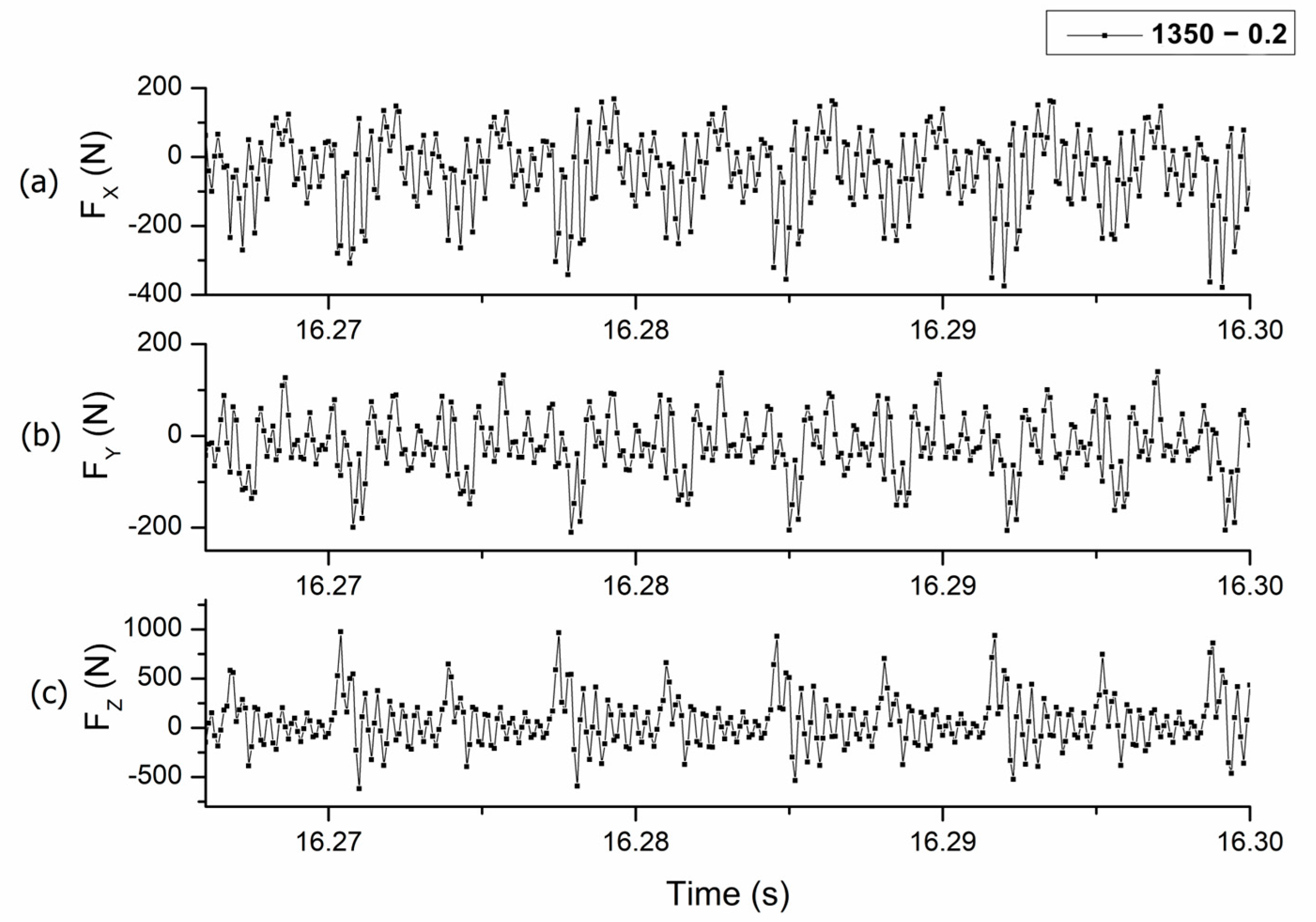
The measurement of cutting force serves as an important indicator for evaluating cutting performance accurately. Under fixed cutting parameters (vc = 1350 m/min and fz = 0.2 mm/tooth), cutting force signals were observed during the milling of UNS S32750 alloy (Figure 2). These signals illustrate the fluctuating chip thickness, ranging from zero to its maximum, due to the intermittent contact between the SiAlON tool inserts and the alloy [25]. The cutting forces signals demonstrated the same performance for the other cutting conditions tested. As a result, the corresponding cutting forces display a periodic trend, reflecting the alternating cutting-in and cutting-out processes. It is also evident that the force component in the Z direction is the most significant, representing the primary component of the resultant cutting force, as also reported by Ming et al., 2021 [26].
The cutting force components in the X, Y, and Z directions are denoted as FX, FY, and FZ, respectively. The resultant cutting force, FR, is defined as follows:
F R = F X 2 + F Y 2 + F Z 2
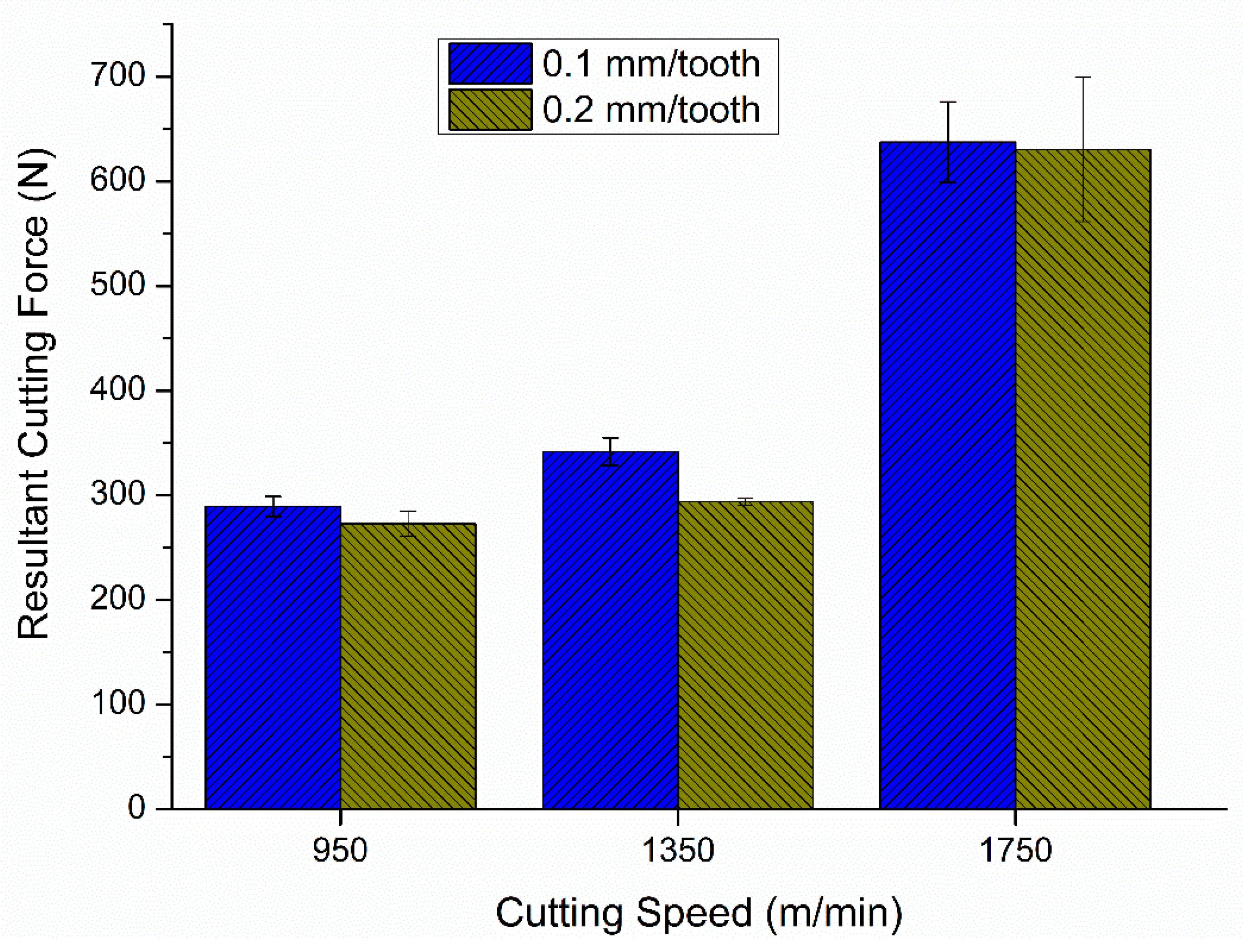
To examine the variation trend of cutting forces, the resultant cutting force was chosen. The evolution of resultant cutting forces with tested cutting parameters is illustrated in Figure 3.
Notably, the average resultant cutting force remains lower and similar for cutting speeds of 950 m/min and 1350 m/min. This observation may be attributed to changes in the shear angle caused by the softening of the workpiece material at high temperatures [27]. However, an increase in the average resultant cutting force is observed with a cutting speed of 1750 m/min, likely due to severe tool wear and elevated cutting temperature.
As the flank wear increased, there was a corresponding rise in cutting force. This phenomenon can be attributed to the reduction in tool clearance angle caused by flank wear, which in turn enlarges the contact area between the flank and the workpiece surface. Consequently, increased friction in the contact region leads to higher cutting forces [28]. This is even more important when considering the machining of the UNS S32750 alloy due to its low thermal conductivity and susceptibility to strain hardening.
Comparing the two different feed rates, the forces are similar for all the cutting speeds tested. With higher feed rates, the chip thickness is theoretically higher, which would cause an increase in the force levels. However, when using the lowest feed rate, the workpiece material deformation was higher, which could have caused the work hardening of the workpiece material during chip formation. This will be further explored in the plastic strain rate analysis. This phenomenon caused the forces to be similar.
In the high-speed machining of UNS S32750 with ceramic tools, achieving the optimal balance among various factors is crucial. These factors include work hardening, strain sensitivity, strain rate sensitivity, and thermal softening, as observed in studies conducted by Molaiekiya et al., 2020 [29]. The increase in cutting forces can be partially attributed to the rise in UNS S32750 steel flow stress. Additionally, the formation of a build-up edge on the cutting edge, resulting from the extreme weldability of the softened workpiece to the tool, contributes to this increase. Finding the proper balance between these competing phenomena is critical. In this regard, cutting speeds of 950 to 1350 m/min provide the best balance, resulting in reduced cutting forces.
Further analyses were conducted to assess the impacts of both cutting speed and feed rate on cutting force. The Pareto chart analysis indicates that the sole parameter significantly influencing cutting force is the cutting speed (Figure 4). The findings reveal that the primary factors affecting the process are temperature and strain rate, which are intricately tied to cutting speed. Both are critical variables in machining operations, with cutting speed acting as a key determinant. Elevated cutting speeds commonly result in heightened temperatures and strain rates due to higher friction and deformation effects. This explains the fundamental role of cutting speed in cutting process conditions and outcomes, especially for alloys that have low thermal conductivity and susceptibility to strain hardening.
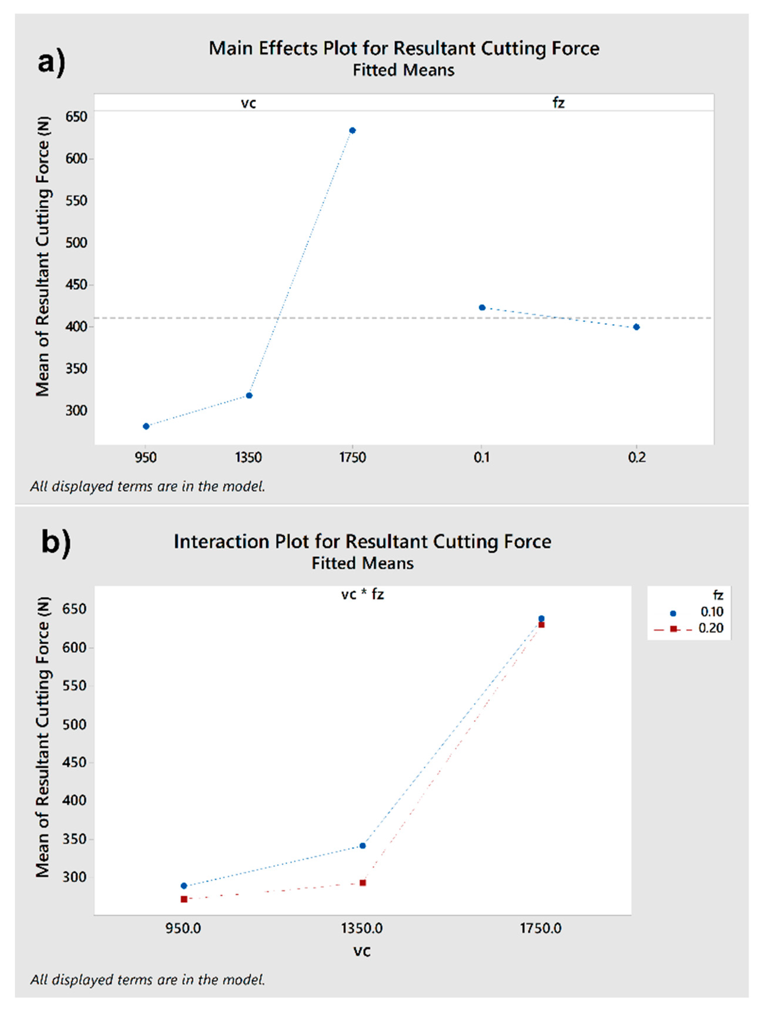
The main effects of cutting force and the interaction between cutting parameters are presented in Figure 5. Consistent with the Pareto chart, which outlines the primary influences of cutting force, cutting speed (vc) emerges as the most influential factor. This is evidenced by the steeper slope of the line representing vc compared to the relatively flat slope of fz. Additionally, the interaction between cutting speed (vc) and feed rate (fz) shows minimal differentiation between the two feed rates (0.1 and 0.2 mm/tooth).

3.2. Chip Morphology and Friction Analysis

After machining, the chip types and morphology were analyzed for each cutting parameter.
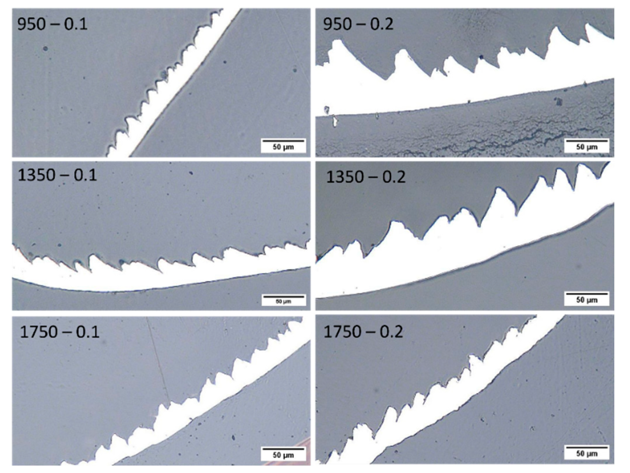
Figure 6 shows optical images of the chips corresponding to the tested cutting parameters, revealing their similar serrated shapes.
To qualitatively assess the impact of cutting speed on SDSS deformation, numerous chips were gathered from various speed ranges and meticulously mounted perpendicular to their leading edges. Subsequently, these chips were subjected to a grinding and polishing process to reduce dimensional inaccuracies. The resulting morphology of typical serrated chips at different cutting speeds and feed rates is shown in Figure 7.
It has been observed that as cutting speed increases, the chips tend to become thinner when using fz = 0.2 mm/tooth. No significant difference in thickness is observed when compared to samples using fz = 0.1 mm/tooth. The changing of the shape of chips is primarily attributed to two factors: the increasing of the cutting edge radius and the effective rake angle due to tool wear, along with the chip thinning effect resulting from milling at higher cutting speeds [29]. Additionally, severe segmentation occurs at high cutting speeds, which produces the breaking of chips in lamellas (1750 m/min–0.2 mm/tooth) [30].
The chip compression ratio and shear strain serve as critical parameters for characterizing chip deformation. Employing the standard methodologies introduced by Shaw (2005) [21], key parameters including the chip compression ratio (CCR), shear angle, cutting force, and friction coefficient at the tool–chip interface were determined. Higher values of shear angle and CCR signify reduced chip deformation and decreased energy consumption, thereby enhancing the efficiency of the cutting process [20,30]. Table 4 combines the characteristics of the chip calculated by the Merchant method and the resultant cutting forces obtained in the cutting tests. The optimal cutting conditions were identified for a feed rate of 0.2 mm/tooth, exhibiting superior performance at cutting speeds of both 950 and 1350 m/min.
According to the metal cutting theory, one of the most important sources of the cutting force is the friction force between the workpiece and the cutting tool [27]. As shown in Table 4, the tool experienced the lower friction force when the cutting force was lower.
At a cutting speed of 1750 m/min, tool wear became evident even after the first pass. This resulted in significant alteration of the cutting edge’s geometry, consequently affecting chip thickness, and potentially causing inaccuracies. Thus, the chip thickness analysis was not performed for the highest cutting speed.
Typically, the chip type and undersurface morphology serve as direct indicators of the prevailing frictional conditions at the tool–chip interface [21]. In Figure 8, SEM images of chip undersurfaces generated at varying cutting speeds and feed rates provide valuable insights into the frictional behavior intrinsic to the machining process. Notably, at a cutting speed of 1750 m/min and a feed rate of 0.20 mm/tooth, a distinct stick–slip phenomenon is observed on the undersurface of the chips. This phenomenon arises due to the rapid temperature elevation, facilitating the weldability of the workpiece material to the rake face of the tool. Consequently, with increasing cutting speed, chips become more prone to localized melting and adherence to the tool face in the form of built-up edges and layers [29,31].
Through a meticulous examination of the chip thickness measurements and the calculated values for the chip compression ratio, shear angle, and the coefficient of friction documented in Table 4, along with a detailed visual analysis of undersurface characteristics provided in Figure 8, it becomes evident that the frictional conditions at the cutting zone, particularly at the tool–chip interface, varied significantly across different parameters. This comprehensive understanding underscores the importance of fine-tuning machining parameters to optimize frictional conditions and enhance overall machining efficiency. These parameters include a feed rate of 0.20 mm/tooth accompanied by cutting speeds of either 950 or 1350 m/min.
These characteristics combined with the results of the cutting forces confirm that the use of 0.20 mm/tooth and 950 or 1350 m/min promotes lower friction between the chip and tool, enabling lower wear of the cutting tool. The smoother morphology observed in the chips produced during the machining of UNS S32750 alloy, achieved at cutting speeds of either 950 or 1350 m/min as illustrated in Figure 8, indicates an enhancement in thermo-frictional conditions during the cutting process. The cutting parameter shows the ability to improve the friction conditions at the cutting interface, which leads to the rapid flow of the chip on the rake surface, as can be seen on the chip undersurface. This observation is indicative of a favorable redistribution of heat flow: a significant portion of the heat generated during cutting is effectively transferred into the chips, subsequently dissipating as the chips are removed from the workpiece. Smooth morphology with slight peel-off marks was identified with a reduced friction condition.
Furthermore, at higher cutting speeds, the chip undersurface exhibits more pronounced material deformation due to elevated friction conditions at the chip–tool interface. This impedes chip flow and consequently increases the contact area between the tool and chip on the rake face surface, leading to heightened temperatures in the cutting zone. As a result, the increased friction generated high temperatures that adversely impacted the cutting tool, causing chipping and ultimately leading to catastrophic tool failure, as will be demonstrated ahead in this work.
The severe plastic deformation of the chips observed can be attributed to the combination of high cutting temperature and cutting heat. Moreover, with increasing cutting speed, segmented chips are produced as the tendency of thermal softening surpasses that of strain hardening. As the cutting speed rises, the plastic deformation becomes increasingly severe, making the chip calculations for parameters at a cutting speed of 1750 m/min and a feed rate of 0.2 mm/tooth no longer applicable. These findings underscore the critical importance of carefully selecting cutting parameters to mitigate such detrimental effects on tool life and machining efficiency. In high-speed machining (HSM), greater cutting speeds induce higher levels of strain and strain rates within the primary shear deformation zone, consequently generating increased heat within the deforming segments [29].
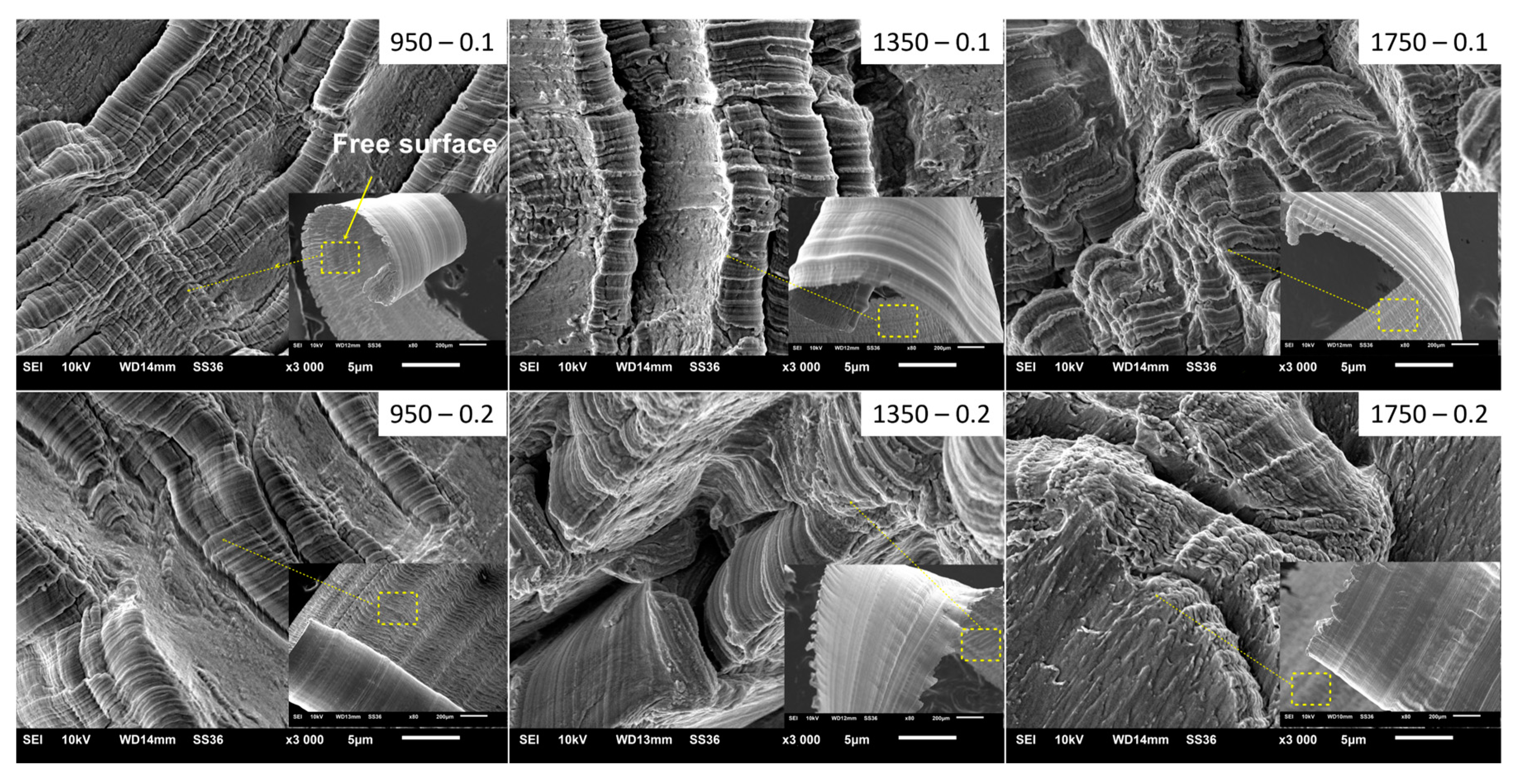
Figure 9 shows chip-free surfaces generated under various cutting parameters. The surface of the chip presents a textured roughness, marked by a lamellar pattern resulting from a slipping mechanism, evident across all cutting speeds. Lamellas are notably smaller and more uniform at lower cutting speeds (950 and 1350 m/min). However, as the cutting speed escalates, the distinct lamella pattern becomes more pronounced, indicating a greater segmentation of the chip (1750 m/min) [30].
Shaw (2005) posits that the formation of a lamellar structure on the chip’s free surface can be elucidated by adiabatic shear theory [21]. According to Molinari et al., 2002, instability in the thermoplastic flow concentrates a significant degree of shear deformation within narrow layers, primarily due to a substantial localized temperature increase, leading to the formation of adiabatic shear bands [32]. Consequently, thermoplastic instability is deemed the primary cause of the catastrophic failure of materials during chip formation.
Adiabatic shear bands emerge within the shear plane, extending from the tool tip with an upward curl toward the tool’s free surface. As the tool progresses, material within the shear plane undergoes extrusion, consistently resulting in surface formation. This iterative process persists continuously. In essence, the gradual slipping of workpiece material layer by layer in front of the tool tip and within the shear plane contributes decisively to the formation of a lamellar structure [32].
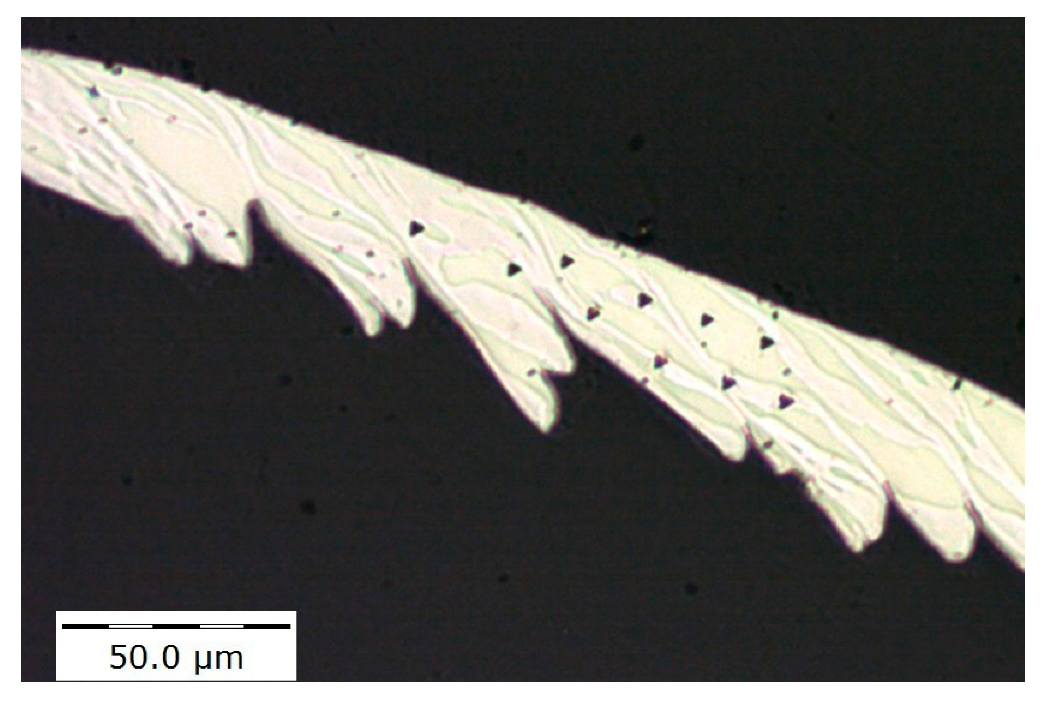
Instrumented nanoindentation has been performed on the cross-section of the chips to measure the change in the hardness of the workpiece material. Ten indentations along the chip have been made within the marked regions depicted in Figure 10, using a Berkovich indenter with 25 mN load and 2 s dwell time.
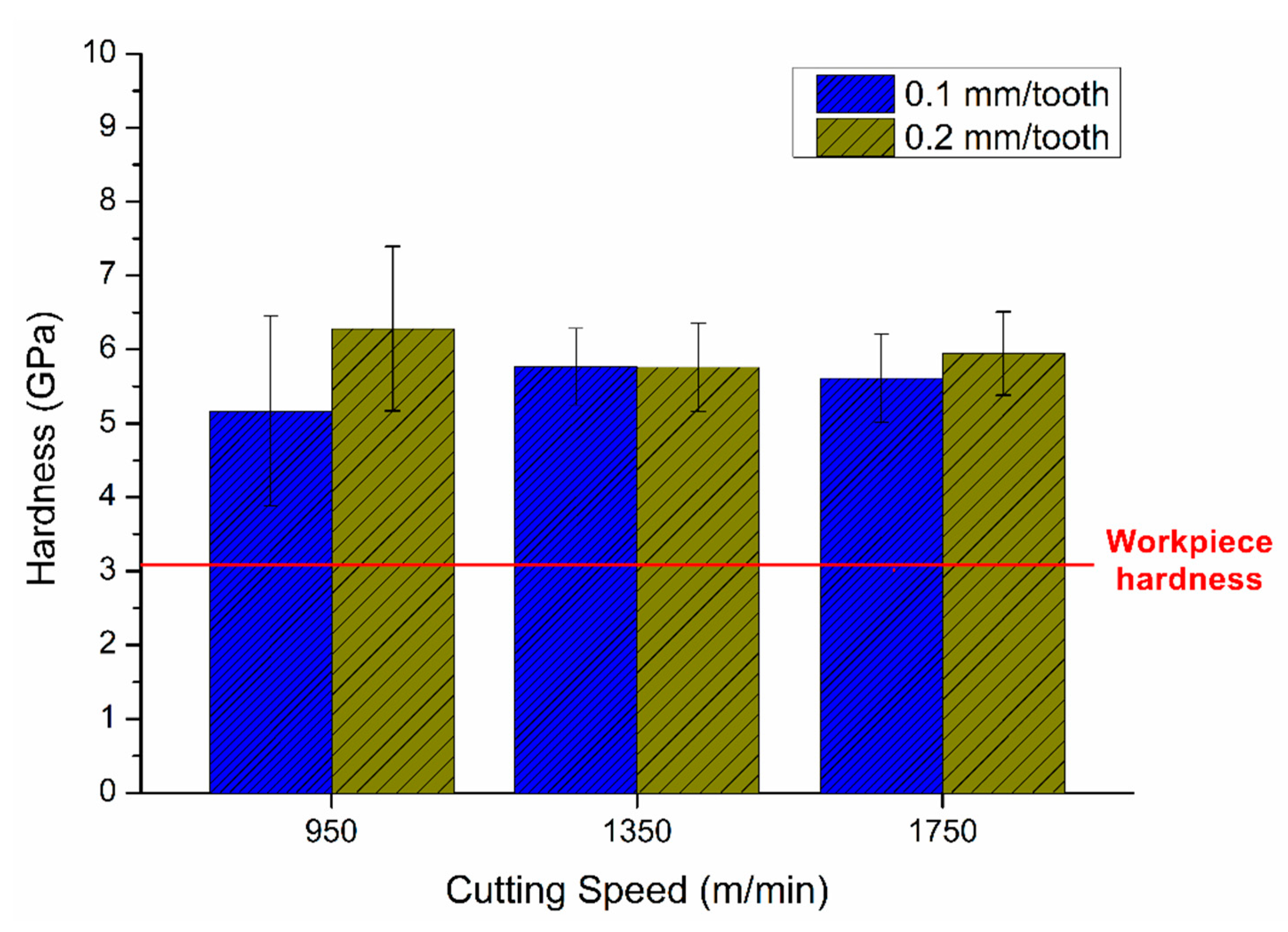
The chips show around 80% higher hardness compared to the undeformed workpiece. The hardness of the as-received material of UNS S32750 alloy is 3.3 ± 0.2 GPa (330 HV), while the hardness of the chips is shown in Figure 11. The hardness of the chips for all the cutting parameters tested has not shown significant differences, fluctuating around 6 GPa (600 HV). The increase in the hardness value is attributed to the UNS S32750’s high sensitivity to strain hardening, which leads to the development of several dislocation barriers in the microstructure and diminishes the dislocation mobility [33].
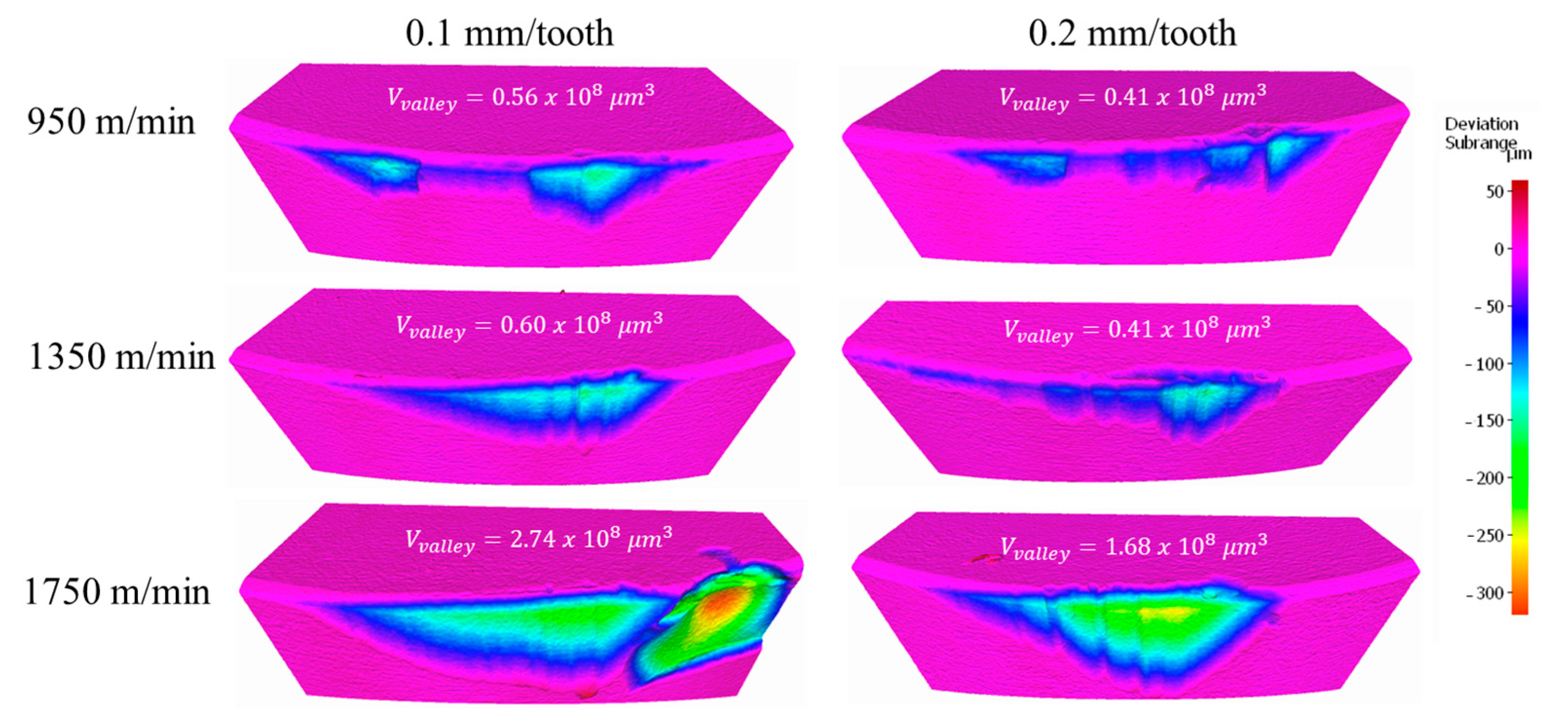
Figure 12 and Figure 13 illustrate the wear patterns of flank faces under varying cutting speeds and feed rates. As the cutting speed increases, there is a tendency for chipping to also rise, as observed in the highest speed for fz = 0.1 mm/tooth. However, when using fz = 0.2 mm/tooth, chipping manifested more gradually with the increase in the cutting speed, especially in regions close to the edge of the tool, as depicted in Figure 13.
When comparing the two different feed rates, the highest feed resulted in chipping in all three cutting speed conditions. At fz = 0.1 mm/tooth, chipping occurred exclusively at the highest speed. However, in this instance, it was primarily associated with built-up edge (BUE) formation, followed by sudden material removal thereafter.
Additionally, the appearance of groove marks caused by abrasive sliding on the flank face indicates abrasive wear. As the cutting speed increases to 1750 m/min, flank wear becomes more pronounced, with abrasive wear occurring in multiple regions. Overall, flank wear is more severe in high-speed cutting operations.
Analyzing the Alicona images (Figure 13), it is noticeable how the tool wear progresses with the increase in cutting speeds. The volumetric wear is gradually higher when using higher cutting speeds, the only exception is with 0.1 mm/tooth and 1750 m/min where significant chipping happened. This chipping is characteristic of adhesive wear. Because of the low thermal conductivity of both, the tool and workpiece materials, the temperature of the cutting zone rapidly exceeded 1000 °C, as will be discussed further in Section 3.4. Consequently, at such high cutting temperatures, there was a propensity for chips or workpiece materials to bond to the tool surface, resulting in adhesive wear [27]. In general, the substantial cutting force and elevated cutting temperature were likely to increase tool wear under ultra-high-speed cutting conditions.

3.3. Workpiece Surface Roughness

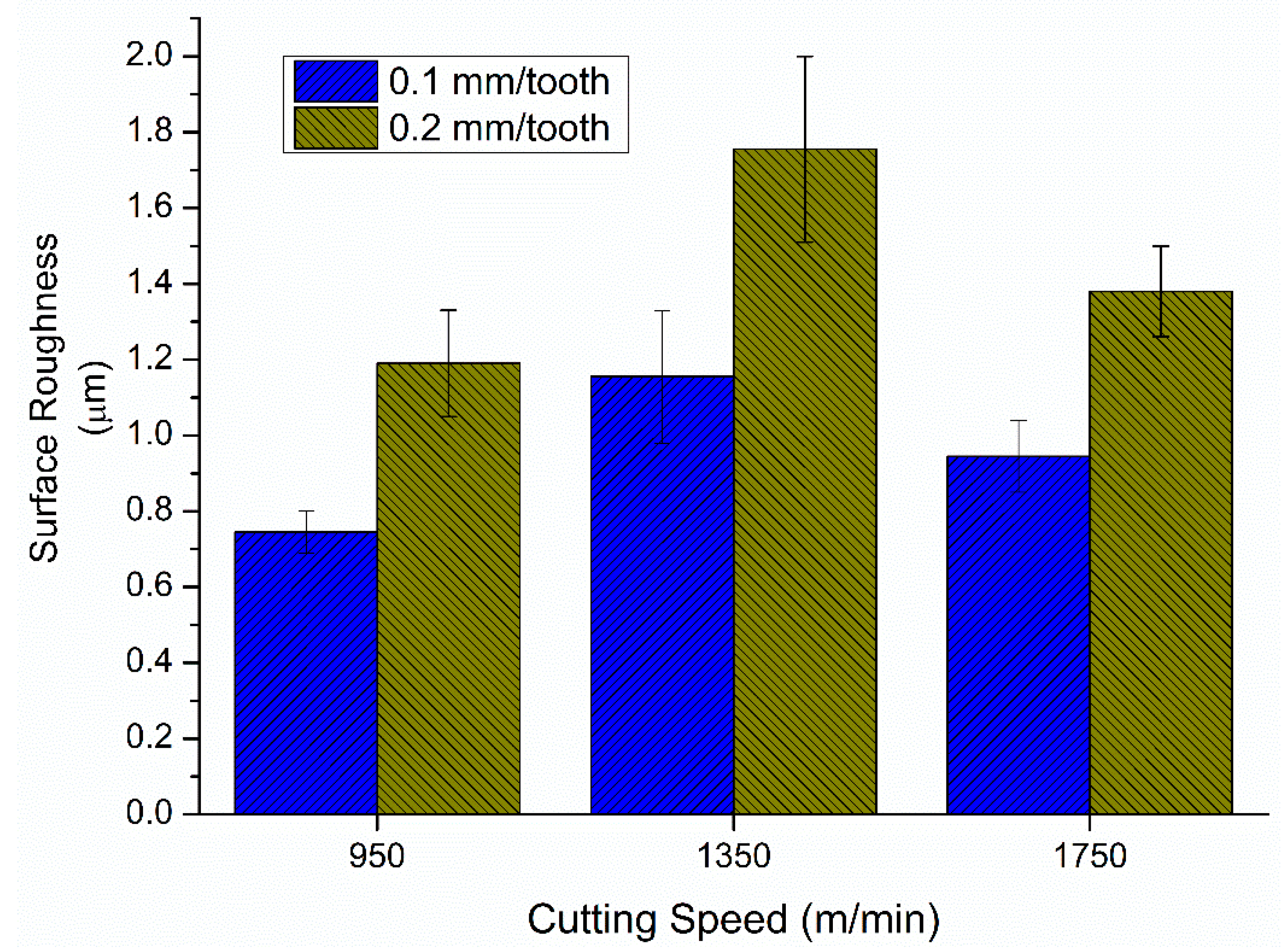
The surface roughness of the SDSS workpiece is shown in Figure 14. The increase in the feed rate from 0.1 to 0.2 mm/tooth increased the surface roughness for all the cutting speeds tested. Notably, the combination of a feed rate of 0.2 mm/tooth and a cutting speed of 1350 m/min caused the most pronounced surface roughness. This is what was already expected since the feed is geometrically related to the surface roughness [31].
The influence of the cutting speeds on the surface roughness showed that the increase in the cutting speed from 950 to 1350 m/min generated higher surface roughness levels. The rise in surface roughness is mostly attributed to elevated temperatures within the workpiece, which may have enhanced lateral material flow, adding to the overall increase in surface roughness. Additionally, an alternative hypothesis presumes that this increase could be attributed to chipping wear occurring on the inserts (see Figure 13).
Nevertheless, increasing the cutting speed from 1350 to 1750 m/min resulted in a decrease in surface roughness. In this case, the variation in the surface roughness is intricately linked to the wear experienced by the cutting edge. The deformation occurring on the cutting edge led to increased deformation of the workpiece material, thereby facilitating a smoothing effect on the workpiece surface.
In terms of material removal rate, the combination of a cutting speed of 1350 m/min and a feed rate of 0.2 mm/tooth proves superior. These parameters not only facilitate a higher quantity of material removed but also lead to lower forces, reduced friction conditions, and minimized tool wear. However, it is essential to note that these conditions also correlate with higher surface roughness levels. This presents a crucial decision point: whether to prioritize achieving a surface with minimal roughness or prolonging the tool’s lifespan.
In the context of machining super duplex stainless steel, surface integrity holds primary importance due to its critical applications. It significantly influences corrosion and fatigue resistance, which are essential properties in such demanding environments. Therefore, it is crucial to achieve a precise equilibrium in optimizing machining parameters between efficient material removal and preserving surface integrity to ensure long-term performance and reliability.

3.4. Finite Element Analysis

In order to establish a connection between the data gathered through experimentation, a finite analysis simulation was conducted to determine the values of cutting temperature and strain rate. These results helped to explain and support the earlier analysis of the impact of cutting temperature on the chips and tool wear, as well as the effect of the strain rate.
Figure 15 illustrates the temperature distribution and plastic strain rate at the tool tip during the finite element modeling (FEM) simulation under the cutting conditions (1350 m/min and 0.2 mm/tooth) and shear friction factors. No significant adverse effects or damage were observed on either the workpiece or the cutting tool, aligning with experimental test results and highlighting these conditions as favorable for minimizing friction.
Similar outcomes were observed at a cutting speed of 950 m/min and a feed rate of 0.2 mm/tooth. However, increasing the cutting speed from 950 to 1750 m/min with a feed rate of 0.2 mm/tooth resulted in a cutting temperature rise from 930 °C to 1000 °C, potentially leading to chip adhesion and amplified tensile residual stress on the machined surface [34]. The chip temperature significantly exceeded other locations, absorbing most of the heat generated during cutting [35].
The interplay between strain hardening and thermal softening influenced the resultant flow stress of the material. Strain hardening increased resistance to deformation, while thermal softening decreased it [30].
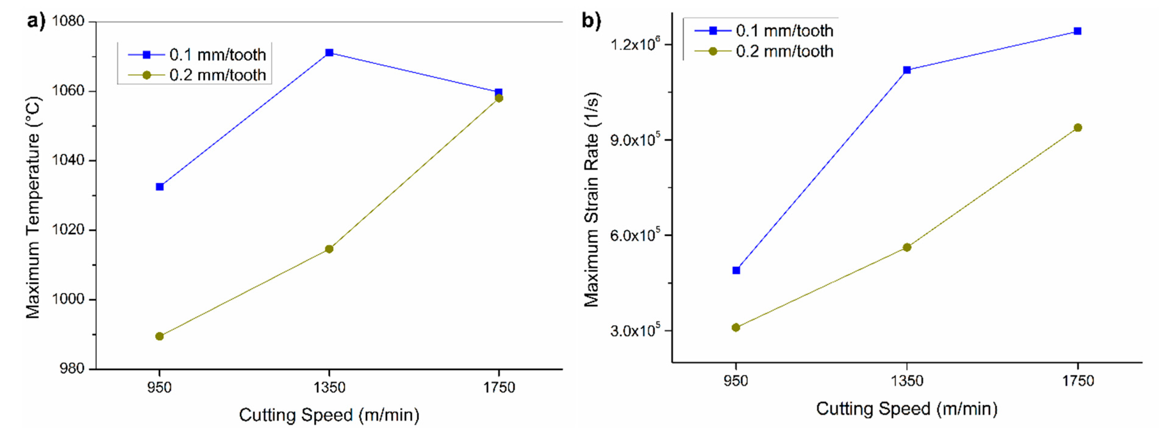
The results of the FEM for all the cutting parameters in terms of maximum temperature and the plastic strain rate are shown in Figure 16. The low thermal conductivity inherent in the UNS S32750 alloy impedes the rapid dissipation of heat generated during machining. Consequently, there is a substantial elevation in temperature within the deformation zones, leading to the thermal softening of the work material [30]. As cutting speed increased, temperature and strain rate rose, facilitating cutting due to thermal softening.
At the highest cutting speed tested (1750 m/min) combined with a feed rate of 0.1 mm/tooth, an unexpected temperature decrease occurred despite the increased cutting speed. Elevating strain rates at ultra-high speeds can effectively lower cutting heat [36], and chip accumulation during cutting may further decrease the temperature in the cutting zone. Consequently, cutting heat may be diminished by increasing both cutting speeds (vc) and strain rates in high-speed cutting processes.
The experimental investigation into tool wear and chip formation, complemented by FEM analysis, revealed a correlation between cutting conditions and machining outcomes. Elevated cutting speeds resulted in increased tool wear and distinct chip morphologies, consistent with FEM predictions of heightened cutting temperatures and strain rates. Conversely, reduced tool wear and smoother chip morphologies were observed at cutting speeds ranging from 950 to 1350 m/min, particularly for a feed rate of 0.2 mm/tooth, validating the accuracy of the FEM model.

3.5. Implications and Future Prospects

While the findings contribute significantly, it is important to note that this research has certain limitations. Firstly, the finite element analysis employed simplifies and assumes frictional behavior, potentially overlooking key dynamics. Therefore, future research needs to focus on developing better friction models that can effectively capture the intricacies of the tool–chip interface.
It is important to recognize the limitations imposed by the FEM software, which often restrict the use of a fixed friction coefficient set at 0.5. However, machining involves more intricate friction mechanisms, necessitating advanced models tailored to the unique circumstances at the tool–chip interface. Additionally, this study only focused on fixed depth of cut, and factors such as coolant application, tool coatings, and alternative sets of cutting parameters were not investigated. Moreover, the influence of cutting parameters on surface integrity aspects beyond surface roughness, such as residual stresses or microstructural alterations, was not studied.
Understanding these factors is important to assess material performance and comprehend the implications of machining processes. To address these limitations, future research should undertake a broader investigation considering a wider range of parameters and materials. This may involve conducting experimental studies with varied cutting conditions and materials, along with employing advanced modeling techniques to better simulate machining dynamics.
Professionals in the field of manufacturing or materials processing seeking to machine UNS S32750 alloy can benefit from the preliminary findings, which emphasize the essential role of optimized cutting parameters in achieving better results. Based on the observed trends in cutting forces, chip morphology, and friction analysis, a promising starting point for optimization is cutting speeds between 950 and 1350 m/min, combined with a feed rate of 0.20 mm/tooth. These conditions have shown potential for reduced cutting forces, minimized friction at the tool–chip interface, and extended tool life. However, professionals are advised to conduct further experimentation and validation in their specific machining environments to adjust these parameters effectively and ensure optimal performance, reliability, and surface integrity.
Expanding on the study’s implications, it is pertinent to consider how the findings might translate to other machining methods, like turning. While the focus was primarily on milling, the underlying principles regarding cutting forces, chip formation, and friction analysis likely have broader relevance. However, variations in tool geometry, cutting dynamics, and material behavior could lead to differing outcomes in turning operations. Thus, although the study provides valuable insights, additional research on turning or other machining processes is necessary to validate the generalizability of these findings across various machining contexts.

4. Conclusions

This paper aims to explore the cutting responses of SiAlON ceramic cutting inserts during high-speed milling of super duplex stainless steel. It quantifies the impact of cutting variables on the machinability of this alloy including cutting forces, chip analysis, cutting temperatures, plastic strain rate, tool wear, and surface roughness. Based on the results obtained, the following statements and conclusions can be drawn:
  • The analysis of cutting forces exposed a significant influence on cutting speed, with lower forces obtained at cutting speeds of 950 and 1350 m/min. However, with an even higher cutting speed (1750 m/min) the cutting forces were intensified, particularly when severe tool wear was present. Moreover, increased flank wear affected the cutting forces due to reduced tool clearance angle and increased friction.
  • Pareto chart analysis identifies cutting speed as the crucial factor for machining outcomes, particularly with low thermal conductivity and strain-hardening alloys.
  • Chip morphology analysis revealed that smoother chip surfaces reduced deformation and lower coefficients of friction were achieved at cutting speeds of 950 and 1350 m/min, combined with a feed rate of 0.2 mm/tooth. These conditions significantly enhanced machining efficiency.
  • SEM images of the chip reveal stick–slip phenomena at 1750 m/min and 0.2 mm/tooth, indicating thermoplastic instability through lamellar patterns.
  • The combination of a 0.2 mm/tooth feed rate and 1350 m/min cutting speed yields the most pronounced surface roughness. Elevated cutting speeds from 950 to 1350 m/min result in higher surface roughness levels possibly due to increased temperatures and lateral material flow.
  • Finite element analysis confirmed the experimental findings, emphasizing the critical role of cutting speed and feed rate in controlling temperature and strain rate during the machining process.
  • The optimal combination for maximizing material removal rate, minimizing tool wear, and reducing forces is a cutting speed of 1350 m/min and a feed rate of 0.2 mm/tooth. However, this leads to higher surface roughness, prompting a decision between surface quality and tool life. In machining super duplex stainless steel, prioritizing surface integrity is crucial for corrosion and fatigue resistance. Finding the right balance between tool wear and surface integrity is vital for long-term performance and reliability in demanding applications.

Author Contributions

Conceptualization, M.G.; Software, V.S.; Validation, Q.H.; Writing—original draft, M.G.; Writing—review & editing, J.M.D. and A.D.; Supervision, S.V. All authors have read and agreed to the published version of the manuscript.

Funding

This research received no external funding.

Data Availability Statement

Data are contained within the article.

Conflicts of Interest

The authors declare no conflict of interest.

References

  1. Strubbia, R.; Hereñú, S.; Marinelli, M.C.; Alvarez-Armas, I. Fatigue damage in coarse-grained lean duplex stainless steels. Mater. Sci. Eng. A 2016, 659, 47–54. [Google Scholar] [CrossRef]
  2. Cvijović, Z.; Radenković, G. Microstructure and pitting corrosion resistance of annealed duplex stainless steel. Corros. Sci. 2006, 48, 3887–3906. [Google Scholar] [CrossRef]
  3. Gowthaman, P.S.; Jeyakumar, S.; Saravanan, B.A. Machinability and tool wear mechanism of Duplex stainless steel—A review. Mater. Today Proc. 2020, 26, 1423–1429. [Google Scholar] [CrossRef]
  4. Tucker, J.D.; Miller, M.K.; Young, G.A. Assessment of thermal embrittlement in duplex stainless steels 2003 and 2205 for nuclear power applications. Acta Mater. 2015, 87, 15–24. [Google Scholar] [CrossRef]
  5. Gamarra, J.R.; Diniz, A.E. Taper turning of super duplex stainless steel: Tool life, tool wear and workpiece surface roughness. J. Braz. Soc. Mech. Sci. Eng. 2018, 40, 39. [Google Scholar] [CrossRef]
  6. M’Saoubi, R.; Axinte, D.; Soo, S.L.; Nobel, C.; Attia, H.; Kappmeyer, G.; Engin, S.; Sim, W.-M. High performance cutting of advanced aerospace alloys and composite materials. CIRP Ann. 2015, 64, 557–580. [Google Scholar] [CrossRef]
  7. Martinho, R.P.; Silva, F.J.G.; Martins, C.; Lopes, H. Comparative study of PVD and CVD cutting tools performance in milling of duplex stainless steel. Int. J. Adv. Manuf. Technol. 2019, 102, 2423–2439. [Google Scholar] [CrossRef]
  8. Nagy, A.I.; Fábián, E.R.; Horváth, R.; Terek, P. Difficulties in the Machining Super Duplex Stainless Steels. Műszaki Tudományos Közlemények 2019, 11, 141–144. [Google Scholar] [CrossRef]
  9. Patra, S.; Agrawal, A.; Mandal, A.; Podder, A.S. Characteristics and Manufacturability of Duplex Stainless Steel: A Review. Trans. Indian Inst. Met. 2021, 74, 1089–1098. [Google Scholar] [CrossRef]
  10. Zhang, W.; Wang, X.; Hu, Y.; Wang, S. Quantitative Studies of Machining-Induced Microstructure Alteration and Plastic Deformation in AISI 316 Stainless Steel Using EBSD. J. Mater. Eng. Perform. 2018, 27, 434–446. [Google Scholar] [CrossRef]
  11. Sharman, A.R.C.R.C.; Hughes, J.I.I.; Ridgway, K. The effect of tool nose radius on surface integrity and residual stresses when turning Inconel 718TM. J. Mater. Process. Technol. 2015, 216, 123–132. [Google Scholar] [CrossRef]
  12. A240/A240M—24; Standard Specification for Chromium and Chromium-Nickel Stainless Steel Plate, Sheet, and Strip for Pressure Vessels and for General Applications. ASTM Internacional: West Conshohocken, PA, USA, 2024.
  13. Ciftci, I. Machining of austenitic stainless steels using CVD multi-layer coated cemented carbide tools. Tribol. Int. 2006, 39, 565–569. [Google Scholar] [CrossRef]
  14. Parsi, P.K.; Kotha, R.S.; Routhu, T.; Pandey, S.; Dwivedy, M. Machinability evaluation of coated carbide inserts in turning of super-duplex stainless steel. SN Appl. Sci. 2020, 2, 1933. [Google Scholar] [CrossRef]
  15. Mativenga, P.T.; Abukhshim, N.A.; Sheikh, M.A.; Hon, B.K.K. An Investigation of Tool Chip Contact Phenomena in High-Speed Turning Using Coated Tools. Proc. Inst. Mech. Eng. Part B J. Eng. Manuf. 2006, 220, 657–667. [Google Scholar] [CrossRef]
  16. Ning, Y.; Rahman, M.; Wong, Y.S. Investigation of chip formation in high speed end milling. J. Mater. Process. Technol. 2001, 113, 360–367. [Google Scholar] [CrossRef]
  17. Zhang, H.; Dang, J.; Ming, W.; Xu, X.; Chen, M.; An, Q. Cutting responses of additive manufactured Ti6Al4V with solid ceramic tool under dry high-speed milling processes. Ceram. Int. 2020, 46, 14536–14547. [Google Scholar] [CrossRef]
  18. Hotta, M.; Hojo, J.; Komeya, K.; Tatami, J.; Meguro, T.; Masuda, H.; Morinaga, K.; Cheng, Y.-B. Preparation of Ca-α SiAlON hollow spheres by carbothermal reduction–nitridation of CaO–Al2O3–SiO2 glass. Mater. Lett. 2011, 65, 116–118. [Google Scholar] [CrossRef]
  19. Dong, P.; Wang, X.; Zhang, M.; Guo, M.; Seetharaman, S. The preparation and characterization of β-SiAlON nanostructure whiskers. J. Nanomater. 2008, 2008, 282187. [Google Scholar] [CrossRef]
  20. Deng, W.J.; Lin, P.; Xie, C.; Li, Q. Analysis of Large-Strain Extrusion Machining with Different Chip Compression Ratios. J. Nanomater. 2012, 2012, 12. [Google Scholar] [CrossRef]
  21. Shaw, M.C. Metal Cutting Principles, 2nd ed.; Oxford University Press: New York, NY, USA, 2005; ISBN 0-19-514206-3. [Google Scholar]
  22. Molaiekiya, F.; Stolf, P.; Paiva, J.M.; Bose, B.; Goldsmith, J.; Gey, C.; Engin, S.; Fox-Rabinovich, G.; Veldhuis, S.C. Influence of process parameters on the cutting performance of SiAlON ceramic tools during high-speed dry face milling of hardened Inconel 718. Int. J. Adv. Manuf. Technol. 2019, 105, 1083–1098. [Google Scholar] [CrossRef]
  23. Man, X.; Ren, D.; Usui, S.; Johnson, C.; Marusich, T.D. Validation of Finite Element Cutting Force Prediction for End Milling. Procedia CIRP 2012, 1, 663–668. [Google Scholar] [CrossRef]
  24. Rajaguru, J.; Dwivedi, M.; Natarajan, S.; Krishnaswamy, H.; Arunachalam, N. Machining induced residual stress prediction during orthogonal cutting of super duplex stainless steel using CEL approach. J. Manuf. Process. 2022, 82, 474–487. [Google Scholar] [CrossRef]
  25. Bhattacharyya, P.; Sengupta, D.; Mukhopadhyay, S. Cutting force-based real-time estimation of tool wear in face milling using a combination of signal processing techniques. Mech. Syst. Signal Process. 2007, 21, 2665–2683. [Google Scholar] [CrossRef]
  26. Ming, W.; Huang, X.; Ji, M.; Xu, J.; Zou, F.; Chen, M. Analysis of cutting responses of Sialon ceramic tools in high-speed milling of FGH96 superalloys. Ceram. Int. 2021, 47, 149–156. [Google Scholar] [CrossRef]
  27. Zheng, G.; Zhao, J.; Cheng, X.; Xu, R.; Zhao, G. Experimental Investigation on Sialon Ceramic Inserts for Ultra-high-speed Milling of Inconel 718. Mater. Manuf. Process. 2016, 31, 633–640. [Google Scholar] [CrossRef]
  28. Wei, M.; Wu, M.; Xu, J.; Cheng, Y. Influence of Flank Wear on the Microstructure Characteristics of the GH4169 Metamorphic Layer under High-Pressure Cooling. Materials 2023, 16, 2944. [Google Scholar] [CrossRef]
  29. Molaiekiya, F.; Aramesh, M.; Veldhuis, S.C. Chip formation and tribological behavior in high-speed milling of IN718 with ceramic tools. Wear 2020, 446–447, 203191. [Google Scholar] [CrossRef]
  30. Fernández-Abia, A.I.; Barreiro, J.; López De Lacalle, L.N.; Martínez, S.; Martínez, S.; López De Lacalle, L.N.; Barreiro, J.; De Lacalle, L.N.L.; Martínez, S.; Barreiro, J.; et al. Effect of very high cutting speeds on shearing, cutting forces and roughness in dry turning of austenitic stainless steels. Int. J. Adv. Manuf. Technol. 2011, 57, 61–71. [Google Scholar] [CrossRef]
  31. Trent, E.M.; Wright, P.K. Metal Cutting, 4th ed.; Butterworth-Heinemann: Boston, MA, USA, 2000; ISBN 0-7506-7069-X. [Google Scholar]
  32. Molinari, A.; Musquar, C.; Sutter, G. Adiabatic shear banding in high speed machining of Ti–6Al–4V: Experiments and modeling. Int. J. Plast. 2002, 18, 443–459. [Google Scholar] [CrossRef]
  33. Hokka, M.; Gomon, D.; Shrot, A.; Leemet, T.; Bäker, M.; Kuokkala, V.-T. Dynamic Behavior and High Speed Machining of Ti-6246 and Alloy 625 Superalloys: Experimental and Modeling Approaches. Exp. Mech. 2014, 54, 199–210. [Google Scholar] [CrossRef]
  34. Houchuan, Y.; Zhitong, C.; ZiTong, Z. Influence of cutting speed and tool wear on the surface integrity of the titanium alloy Ti-1023 during milling. Int. J. Adv. Manuf. Technol. 2015, 78, 1113–1126. [Google Scholar] [CrossRef]
  35. Jafarian, F.; Umbrello, D.; Golpayegani, S.; Darake, Z. Experimental Investigation to Optimize Tool Life and Surface Roughness in Inconel 718 Machining. Mater. Manuf. Process. 2016, 31, 1683–1691. [Google Scholar] [CrossRef]
  36. Gao, M.; Zhang, K.; Zhou, Q.; Zhou, H.; Liu, B.; Zheng, G. Numerical investigations on the effect of ultra-high cutting speed on the cutting heat and rock-breaking performance of a single cutter. J. Pet. Sci. Eng. 2020, 190, 107120. [Google Scholar] [CrossRef]
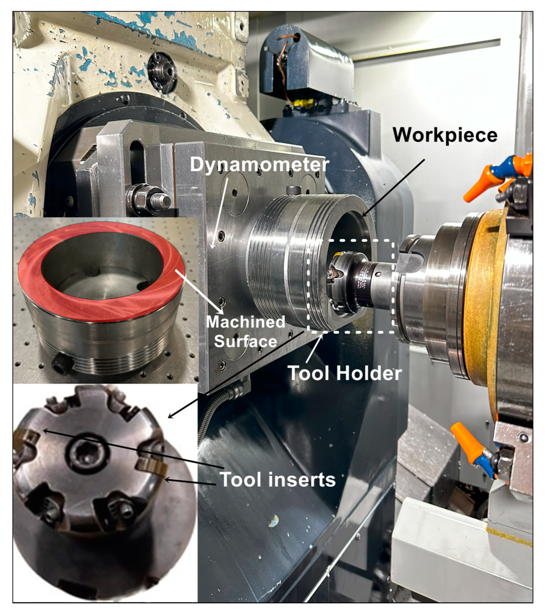
Figure 1. Experimental setup.
Machines 12 00349 g001
Figure 2. Cutting force signals during the milling of UNS S32750 alloy using 1350 m/min and 0.2 mm/tooth: (a) Fx signals, (b) Fy signals, and (c) Fz signals.
Machines 12 00349 g002
Figure 3. Resultant cutting forces.
Machines 12 00349 g003
Figure 4. Pareto chart for the resultant cutting force response.
Machines 12 00349 g004
Figure 5. The resultant cutting forces plots for (a) main effects and (b) interaction.
Machines 12 00349 g005
Figure 6. Morphology of the chip cross-section at different cutting speeds and feed rates.
Machines 12 00349 g006
Figure 7. Optical images of the chips cross-section.
Machines 12 00349 g007
Figure 8. Chip undersurface at different cutting conditions.
Machines 12 00349 g008
Figure 9. SEM images and microscopic characteristics of the free surface of the chips.
Machines 12 00349 g009
Figure 10. Instrumented indentation on the cross-section of the chip.
Machines 12 00349 g010
Figure 11. Results of instrumented hardness measurements in chips under different cutting parameters.
Machines 12 00349 g011
Figure 12. Optical images of the tool wear for the different cutting parameters.
Machines 12 00349 g012
Figure 13. Wear Alicona images of the inserts after one pass.
Machines 12 00349 g013
Figure 14. Surface roughness of the super duplex stainless steel workpiece.
Machines 12 00349 g014
Figure 15. Simulated temperature distributions (a) and strain rate (b) observed at 1350 m/min and 0.2 mm/tooth.
Machines 12 00349 g015
Figure 16. Finite element modeling results depicting (a) maximum temperature and (b) maximum strain rate as functions of cutting speed.
Machines 12 00349 g016
Table 1. Chemical composition, mechanical properties, and thermal properties of the UNS S32750 alloy.
Element Weight Composition (%)CCrNiMoNMnCuPSSi
0.225740.271.20.50.020.010.8
Mechanical and Thermal Properties
Yield Strength
(MPA)
Tensile Strength
(MPa)
Elongation (%)Thermal Conductivity (W/m.K)
5508002514
Table 2. Cutting parameters.
TestCutting Speed (m/min)Feed Rate (mm/tooth)Depth of Cut (mm)
19500.10.25
29500.2
313500.1
413500.2
517500.1
617500.2
Table 3. Parameters used for finite element modeling.
Total number of elements24,000
Maximum element size0.01
Minimum element size0.02
UNS S32750 Properties
Thermal conductivity14 (W/m.°C)
Thermal capacity425 (J/kg.°C)
Density7.8 (g/cm3)
Thermal expansion13 (µm/m/K)
Table 4. Tribological performance of analyzed cutting parameters evaluated through chip characteristics.
Cutting Speed (m/min)—Feed Rate
(mm/tooth)
Chip Compression Ratio
(CCR)
Φ—Shear
Angle (°)
Friction Coefficient (µ)Resultant Cutting Force, Average (N)
950—0.100.8350.60.34289 ± 9
950—0.200.8853.40.23273 ± 12
1350—0.100.8652.70.26342 ± 13
1350—0.200.8853.40.23294 ± 3
1750—0.10N/AN/AN/A637 ± 39
1750—0.20N/AN/AN/A630 ± 69
N/A—not applicable.
Disclaimer/Publisher’s Note: The statements, opinions and data contained in all publications are solely those of the individual author(s) and contributor(s) and not of MDPI and/or the editor(s). MDPI and/or the editor(s) disclaim responsibility for any injury to people or property resulting from any ideas, methods, instructions or products referred to in the content.