Article

Learning-Based Planner for Unknown Object Dexterous Manipulation Using ANFIS

Institute of Industrial and Control Engineering, Universitat Politècnica de Catalunya, BarcelonaTech (UPC), Diagonal, 647, Planta 11 (Edifici ETSEIB), 08028 Barcelona, Spain
*
Author to whom correspondence should be addressed.
Machines 2024, 12(6), 364; https://doi.org/10.3390/machines12060364
Submission received: 11 April 2024 / Revised: 19 May 2024 / Accepted: 22 May 2024 / Published: 23 May 2024

Abstract

:
Dexterous manipulation of unknown objects performed by robots equipped with mechanical hands represents a critical challenge. The difficulties arise from the absence of a precise model of the manipulated objects, unpredictable environments, and limited sensing capabilities of the mechanical hands compared to human hands. This paper introduces a data-driven approach that provides a learning-based planner for dexterous manipulation employing an Adaptive Neuro-Fuzzy Inference System (ANFIS) fed by data obtained from an analytical manipulation planner. ANFIS captures the complex relationships between inputs and optimal manipulation parameters. Moreover, during a training phase, it is able to fine-tune itself on the basis of its experiences. The proposed planner enables a robot to interact with objects of various shapes, sizes, and material properties while providing an adaptive solution for increasing robotic dexterity. The planner is validated in a real-world environment, applying an Allegro anthropomorphic robotic hand. A link to a video of the experiment is provided in the paper.

1. Introduction

Manipulation involves moving or rearranging objects in the environment. This term encompasses various actions, such as grasping and releasing objects, and interaction with the environment and/or objects [1]. Dexterous manipulation especially refers to the ability to achieve different configurations of the manipulated object within the hand workspace [2,3]. Several prior studies on this topic have been conducted [4,5,6,7]. Dexterous manipulation, is carried out basically in two ways, or combinations of them [8]:
  • Keeping each finger in contact with the object during the manipulation, i.e., the grasp varies in a continuous way (e.g., [9,10,11]).
  • “Finger gaiting“ or “in-hand regrasping“, which sequentially removes finger contact(s) and places the finger(s) at another point on the object surface, i.e., the grasp varies in a discontinuous way (e.g., [9,12,13]).
Numerous recent works focus on the dexterous manipulation of unknown objects, where “unknown object” refers to an object whose shape and other properties are unknown when the manipulation begins [8]. The application of force optimization for the manipulation of unknown objects is presented in [14], and online improvement of the hand movements while manipulating an object is described in [15,16,17]. The use of virtual contact points to solve the dexterous manipulation of unknown objects is presented in [8], and the teleoperated dexterous manipulation by an operator using an input interface, such as a keyboard, is carried out in [18], where the task is carried out by the hand following the directions of the operator.
Since the real world is so diverse, it is unrealistic for a robot to rely solely on a pre-existing accurate model of its surroundings.The robot must be able to adapt itself to new environments. In this context, machine learning may play a key role in the problem of robot manipulation. The approaches to allowing a robot to learn to manipulate objects range from learning specific manipulation skills from human demonstration to learning abstract descriptions of a manipulation task for discovering an object’s functionality through interaction, and many more in between. These can typically be categorized into five types [19]:
  • Learning representations of the object and the environment: The robot learns the state characteristics and degrees of freedom of each object in its environment, e.g., learning object pose [20], shape [21], and material properties [22].
  • Learning a transition model of the environment: The robot learns how its actions affect the task state [23,24].
  • Learning skill policies: The robot learns to obtain a behavior or skill controller to perform a desired manipulation task [25,26,27].
  • Learning to characterize skill: The robot learns a model of the results of the manipulation. A post-condition model describes the areas of the state space that the robot will go after using a skill [28,29,30].
  • Learning compositional and hierarchical structure: The robot learns hierarchical knowledge that will improve its ability to solve new tasks [31,32,33].
The application of learning techniques to dexterous manipulation is the subject of many works. A framework of dexterous imitation learning for dexterous manipulation is presented in [34]; it requires a single RGB camera to observe a human operator and teleoperate the robotic hand. Reinforcement learning (RL) is used to learn dexterous manipulation policies that can perform vision-based object reorientation on a physical Shadow dexterous hand [25,35]. The use of data obtained from human demonstrations to learn the dexterous manipulation of the desired object is proposed in [36,37].
The adaptive neuro-fuzzy inference system (ANFIS) is another learning technique that was created by combining artificial neural networks (ANN) and fuzzy logic, two powerful soft computing frameworks [38]. ANFIS is a system capable of modeling complex, non-linear relationships between inputs and outputs and is commonly used in machine learning and control systems to approximate and represent functions that may be difficult to describe using mathematical equations. ANFIS requires less data for training compared to deep neural networks, making it suitable for scenarios with limited data sets. Moreover, ANFIS offers a transparent and interpretable model which is valuable in applications where understanding the reasoning behind decisions is crucial. The input and output training data are used to adjust the ANFIS parameters for robot navigation [39]. Taking advantage of the ANFIS controller for mobile robot navigation is presented in [40,41]. The application of multiple ANFIS models for object shape recognition is depicted in [42].
Data generation is another crucial component in the application of learning methods, including ANFIS. There are various methods for providing the required data for dexterous manipulation based on employing various sensing and data collection techniques. Optical tracking systems [43], magnetic sensors [44], force and tactile sensors [8], and glove-based sensors [45] are the most common approaches. Human-to-robot hand motion mapping [46,47] is frequently required in several applications, and the approaches to address this problem fall under the following six categories [45]: direct joint, direct Cartesian, task-oriented, dimensionality reduction-based, pose recognition-based, and hybrid mappings.
In this work, we use a learning-based planner for dexterous manipulation, feeding data obtained from an analytical manipulation planner that uses a heuristic to move the fingers to rotate the object in the desired direction, proposed in [8]. The proposed planner offers an adaptive method to improve robotic dexterity and is tested in the real world using an Allegro anthropomorphic robotic hand [48] with tactile sensors [49] at its fingertips. The structure of the rest of the paper is the following: Section 2 describes the problem statement. Section 3 presents the proposed manipulation strategy. Section 4 presents the experimental validation. Finally, Section 5 draws the main conclusions of the work and proposes future research paths.

2. Problem Statement

This work attempts to find a highly adaptable solution for the dexterous manipulation of unknown objects (i.e., in the absence of a precise model or information about the object geometry and properties, such as varying shapes, sizes, and material properties) with a robotic hand in real-time environmental conditions with limited sensing capabilities. Taking advantage of a data-driven approach, we employ a learning-based planner with two modules: path planner (PP) and inverse kinematics (IK). In addition, no external measurements are available as feedback to obtain information about the position of the object within the hand. The manipulation goal is to rotate the grasped unknown object around the X-, Y-, or Z-axis of a reference system attached to the robotic hand. It is assumed that the unknown object has already been grasped before starting the dexterous manipulation and that three fingers of a robotic hand are employed to grasp and manipulate the object, performing a tripod grasp [50], which operates in the same way as humans do, with the thumb working opposite to the index and middle fingers.

3. Proposed Manipulation Strategy

The manipulation strategy is based on utilizing a learning-based approach instead of a pre-defined manipulation model. ANFIS, as a machine-learning method, can perform well for limited training data, and as an inference learning system, it has the ability to provide an interpretable explicit representation of what ANFIS internally performs. The required data to train ANFIS are obtained from simulation, fixing different grasping configurations, and using a heuristic to move the fingers to rotate the object in the desired direction, as was performed in [8]. The trained ANFIS structure is expected to enable the robotic hand to carry out the same manipulation tasks by computing the finger movements to properly rotate the object during manipulation.

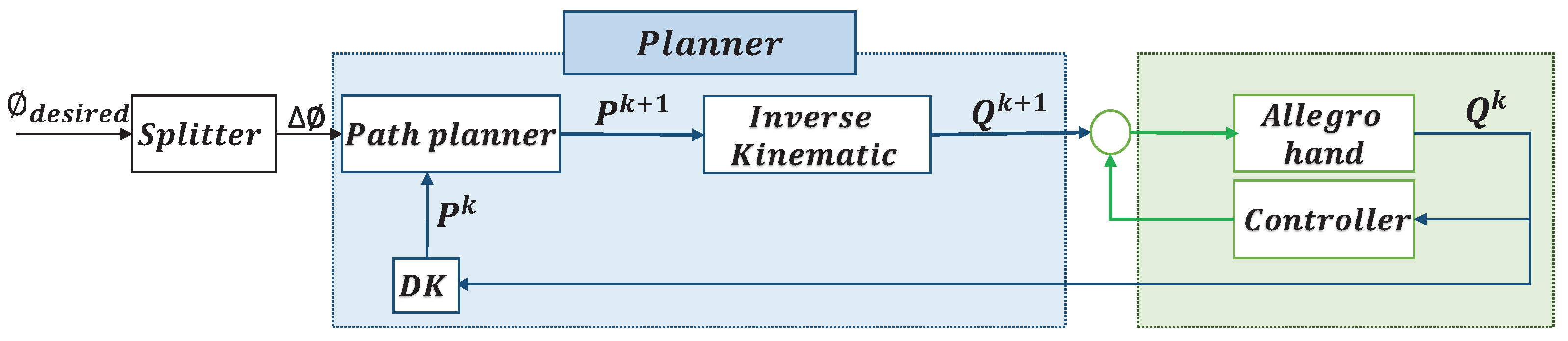
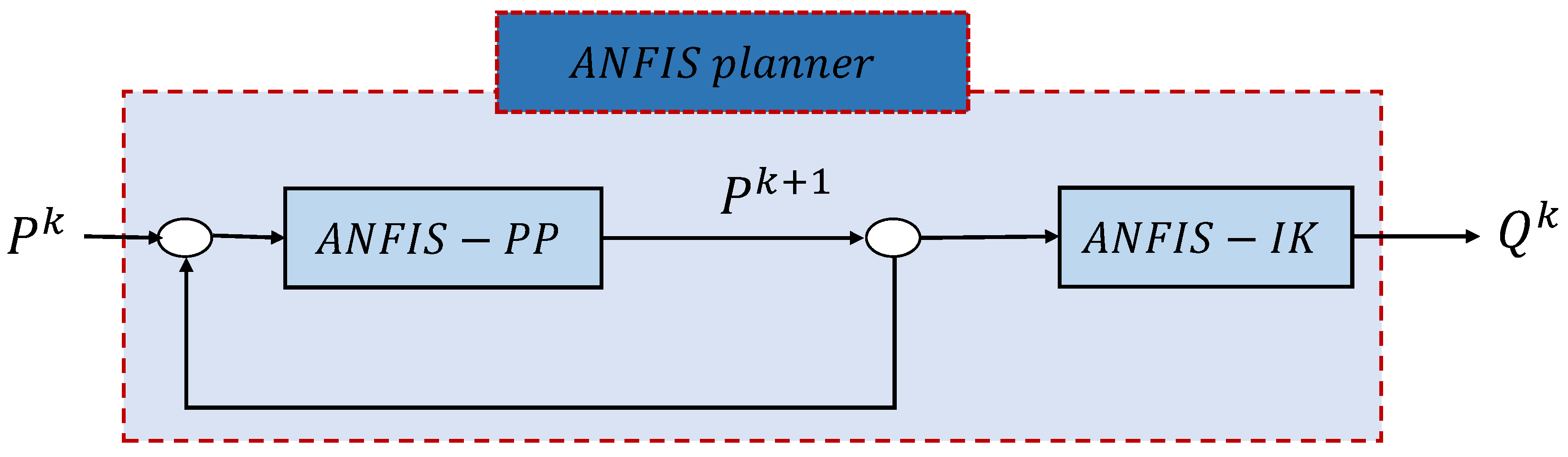
3.1. Overview of the Proposed Manipulation Strategy
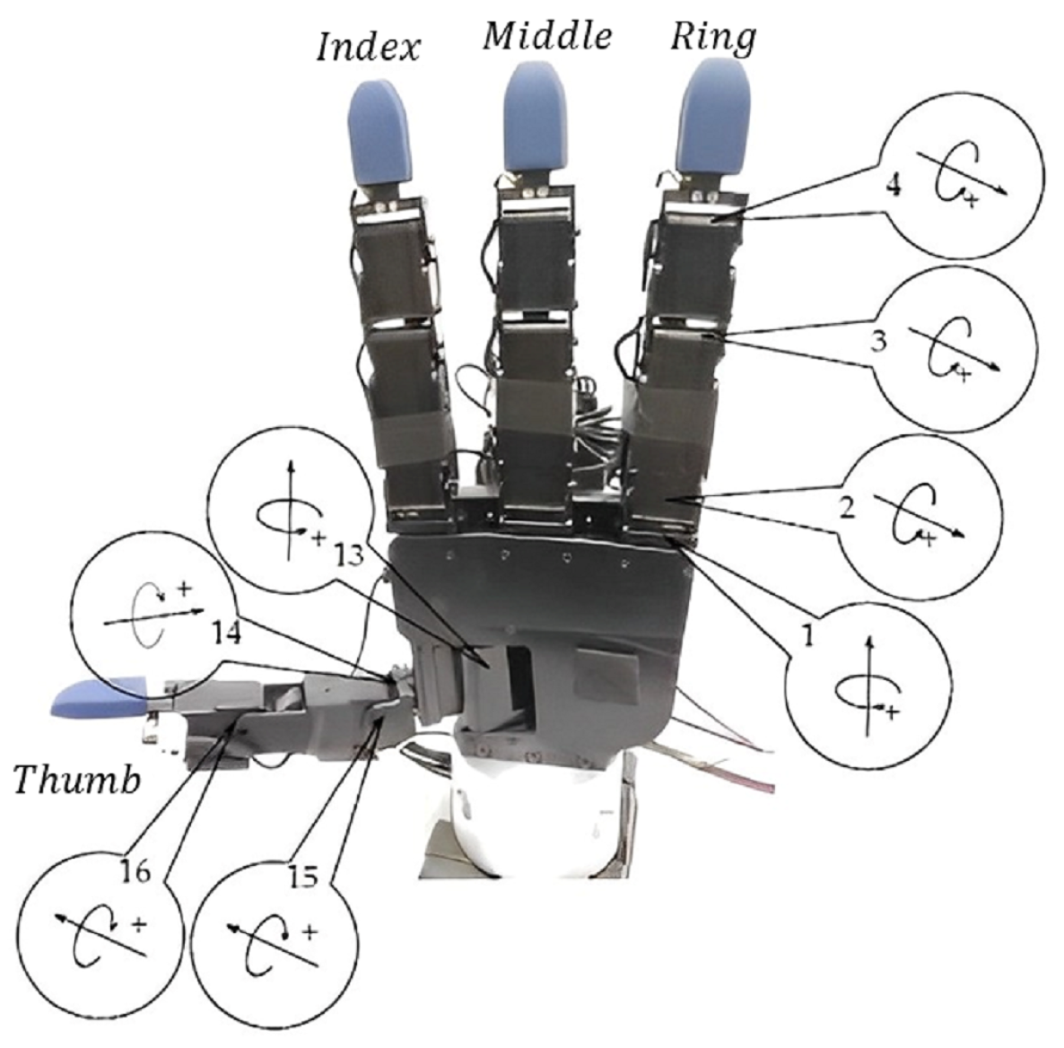
Let us first introduce some basic nomenclature. Consider an anthropomorphic robotic hand, and let:
  • q i j be the position of joint j of finger f i , with i = 1 , , n f and j = 1 , , n j .
  • q i = [ q i 1 q i n j ] be the configuration of finger i.
  • Q = [ q 1 q i q n f ] T be the configuration of the hand.
  • p f i = [ x f i y f i z f i ] be the fingertip Cartesian coordinates of f i expressed in the hand reference system.
  • P = [ p f i p f i p f i ] T be the set of all the fingertips of the hand represented in a matrix.
The main idea of the proposed approach is to use an ANFIS planner to plan the hand movements to produce the dexterous manipulation of unknown objects. The ANFIS planner is a data-driven planner based on a trained and validated ANFIS structure that aims to perform planning tasks. Unlike analytical planners, ANFIS planners have high adaptability and, therefore, can better generalize across a wider range of scenarios. They can learn and adapt their decision-making process based on the observed input–output relationships in the environment. The ANFIS planner predicts values of the next step configuration of the hand ( Q k + 1 ) based on current fingertip positions ( P k ). Figure 1 presents a diagram of the system using an analytical planner that works as follows: The input to the system is the desired total rotation angle of the manipulated object around a given axis, ϕ d e s i r e d , which is split into small rotation steps, Δ ϕ , used as input for each manipulation iteration until the target, ϕ d e s i r e d , is achieved. The current positions of the fingertips, P, are obtained from the current configuration of the hand, Q, and used jointly with the desired rotation, Δ ϕ , by a path planner to determine the proper movements of the fingers to (try) to produce the desired rotation of the object. The planner generates the desired final position of each fingertip, p f i , and using inverse kinematics, the corresponding positions of the hand joints Q are obtained and fed to the control system of the hand. Now, Figure 2 illustrates the alternative proposed diagram using the ANFIS planner. The ANFIS planner replaces the two main components of the analytical planner: on the one side, the path planner is replaced by an ANFIS path planner (ANFIS-PP) that works based on learning from experience and data, and, on the other side, the IK module is also replaced by an ANFIS module (ANFIS-IK) that is previously trained. Even when the IK of a finger is analytically known, since the general goal of the work is to perform object manipulation using only learning approaches, the analytical IK module was replaced by a learning module trying to minimize the required knowledge about the system.
The steps for the development of this ANFIS machine learning planner, detailed in the next subsections, are the following:
  • Step 1: Input and output data generation and preparation.
  • Step 2: Training the ANFIS structure.
  • Step 3: Validate the ANFIS planner in simulation.
  • Step 4: Validate the ANFIS planner in a real-world experiment.

3.2. Input and Output Data Generation and Preparation

Data generation for the training phase can be performed in two ways: (a) using a dataglove to capture the movements of a human hand while performing a manipulation task; (b) running a manipulation task with the robotic hand (either real or in simulation) using any pre-defined manipulation strategy, and capturing the positions of the hand joints during the manipulation process. In any case, in this work, we consider we already have the input data independently of the way they were obtained (which is not relevant for the contribution of this work).
The considered input for the ANFIS-PP training are a data set D [ P k ] of fingertips in Cartesian space at time k, P k , and the corresponding data set D [ P k + 1 ] of outputs P k + 1 after one manipulation iteration, while Δ ϕ is considered a constant (note that it could also be considered as an input variable in the problem). Regarding the ANFIS-IK, the input are a data set D [ P k ] of fingertips in Cartesian space at time k, P k , and the corresponding data set D [ Q k ] of outputs Q k , obtained by using the known inverse kinematics of the hand. These data sets are reprocessed to remove outlier samples using a box whisker (BW) plot [51].

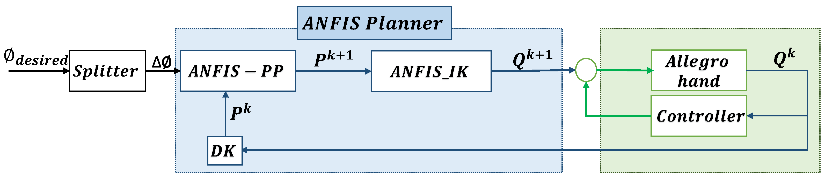
3.3. Learn from Data Using the ANFIS Algorithm

ANFIS stands for “adaptive neurofuzzy inference system”, and it is used to learn a specific model from given input and output data. In this case, it is configured as a neural network that learns the manipulation behavior of the hand from the training data set. Figure 3 shows the ANFIS architecture, which is a five-layer network. Each layer l { 1 , , 5 } involves node(s), input(s) and output(s), and there are also directional links that connect the nodes of each layer. A node is a fundamental element that represents a particular function in each layer. The nodes are as follows: (a) fixed (represented by circles), which have predetermined structures and parameters that do not change during training, and, (b) adaptive (represented by squares), which have parameters that are adjusted during the learning process based on the input data using the back propagation technique and the recursive least squares (RLS) method. Note that the ANFIS structure is multi-input single-output (MISO).
This type of inference system is used to learn:
  • The manipulation movements of each finger f i (ANFIS-PP). In this case, an ANFIS system is used to learn each of the coordinates of the next position of a fingertip (i.e., x f i k + 1 , y f i k + 1 and z f i k + 1 ) from the current ones (i.e., x f i k , y f i k and z f i k ). Thus, the input to the system in Figure 3 is a fingertip position p f i k = [ x f i k y f i k z f i k ] and the output is a coordinate c f i { x f i k + 1 , y f i k + 1 , z f i k + 1 } . This implies that the number of ANFIS systems involved in an ANFIS-PP is equal to three times the number of used fingers since a system as presented in Figure 3 is necessary for each of the three fingertip coordinates of each of the three fingers. Note that this means that the variation in each component of the fingertip depends on the current values of all three components.
  • The inverse kinematics of the fingers (ANFIS-IK). In this case, an ANFIS system is used to learn each of the joint values q R i j of a finger from the Cartesian components of the fingertip position (i.e., x f i , y f i , and z f i ). Thus, the input to the system in Figure 3 is a fingertip position p f i = [ x f i y f i z f i ] and the output is q R i j . This implies that the number of ANFIS systems involved in an ANFIS-IK is equal to the number of joints of each finger.
The proposed structure of the ANFIS system is as follows (see Figure 3):
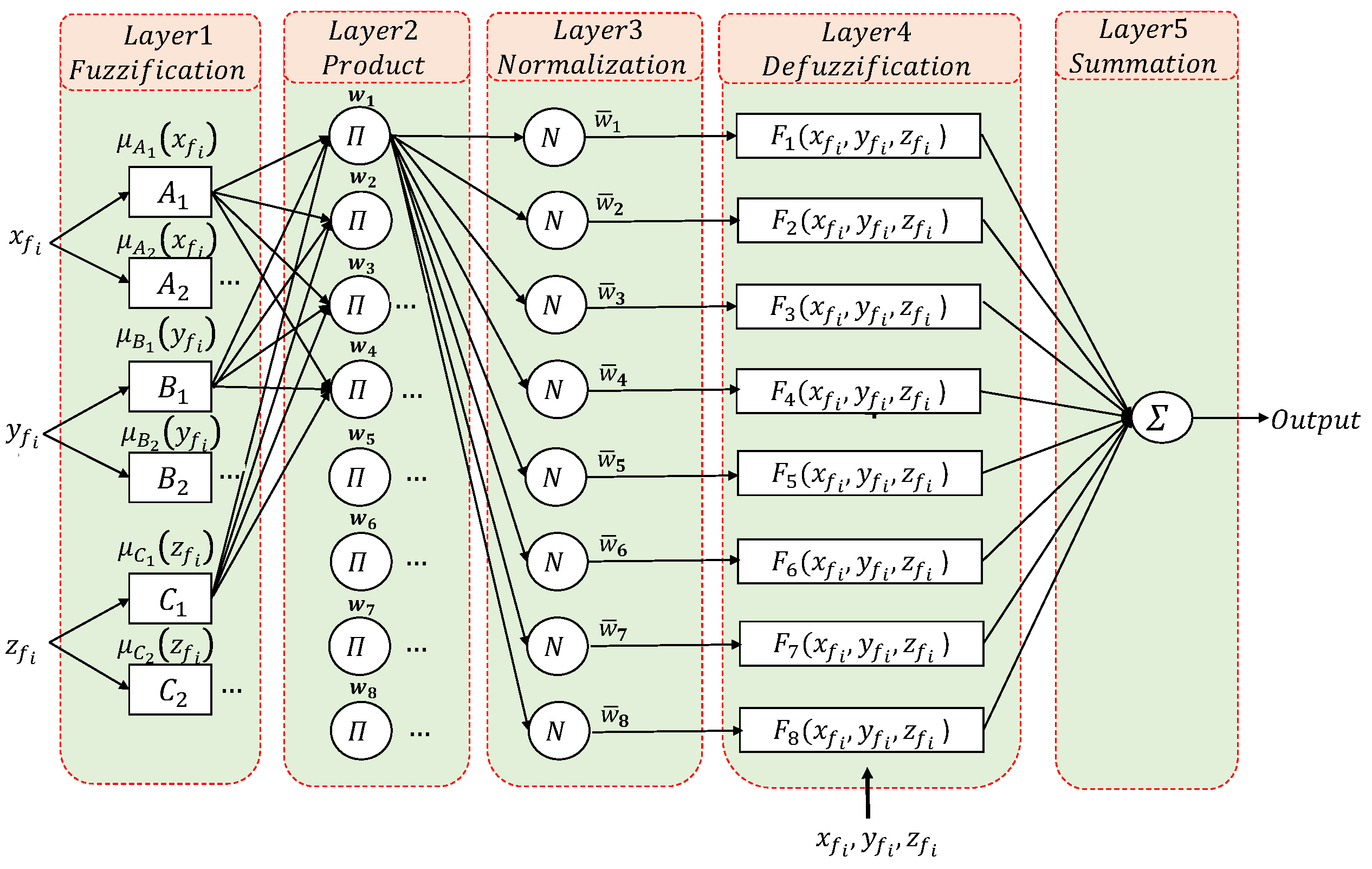
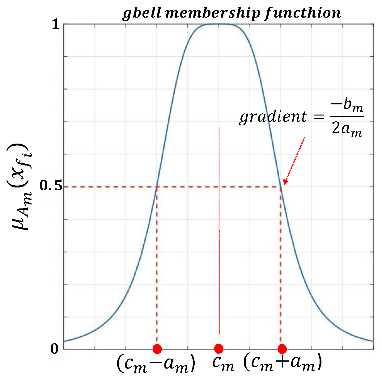
  • Fuzzification layer: In this layer, there are a number of membership functions ( N M F ) for each input, i.e., A m , B m , and C m with m { 1 , , N M F } . N M F is a hyper-parameter selected by humans and based on compromising the accuracy and computational burden. In our particular applications, we choose N M F = 2 . The selected type of these membership functions is a generalized Gaussian bell membership function (see Figure 4) defined as follows:
    μ A m ( x f i ) = 1 + x f i c m a m 2 b m 1 μ B m ( y f i ) = 1 + y f i c m a m 2 b m 1 μ C m ( z f i ) = 1 + z f i c m a m 2 b m 1 ,
    where μ A m , μ B m and μ C m are the fuzzy membership degrees for each input variable, and a m , b m , c m are defined as premise parameters that determine the shape of the membership function and are optimized using back-propagation to minimize the error between the model output and the actual target values.
  • Product Layer: In this layer, there are eight fixed nodes (resulting from three inputs and two membership functions for each one i.e., 2 3 = 8 ). Each node represents a fuzzy rule, labeled π , that outputs the firing strength of each rule w n , n = 1 , , 8 , which multiplies the incoming signals and sends the product out of the layer,
    w n = μ A m ( x f i ) · μ B m ( y f i ) · μ C m ( z f i ) , m = 1 , 2 , n = 1 , , 8
  • Normalization layer: In this layer, there are again eight fixed nodes, labeled N, that output normalized firing strengths ω ¯ n , computed as the ratio of the n t h rules firing strength w n to the sum of all rule’s firing strengths:
    ω ¯ n = ω n n = 1 8 ω n , n = 1 , , 8
  • Defuzzification layer: In this layer, there are eight adaptive nodes with a function F j that outputs the weighted value of a given rule as:
    F n = ω ¯ n · ( p n x f i + q n y f i + t n z f i + r n ) , n = 1 , , 8 ,
    where p n , q n , t n , and r n are defined as consequent parameters that will be trained by a supervised learning algorithm.
  • Summation layer: In this layer, a single fixed node, labeled Σ , outputs one of the coordinates of the fingertip p f i = [ x f i y f i z f i ] as the summation of all incoming signals, i.e., the output of the ANFIS system is either x f i , y f i , or z f i depending on the case,
    c f i = n = 1 8 ω ¯ n ( p n x f i + q n y f i + t n z f i + r n )   with   c f i { x f i , y f i , z f i }

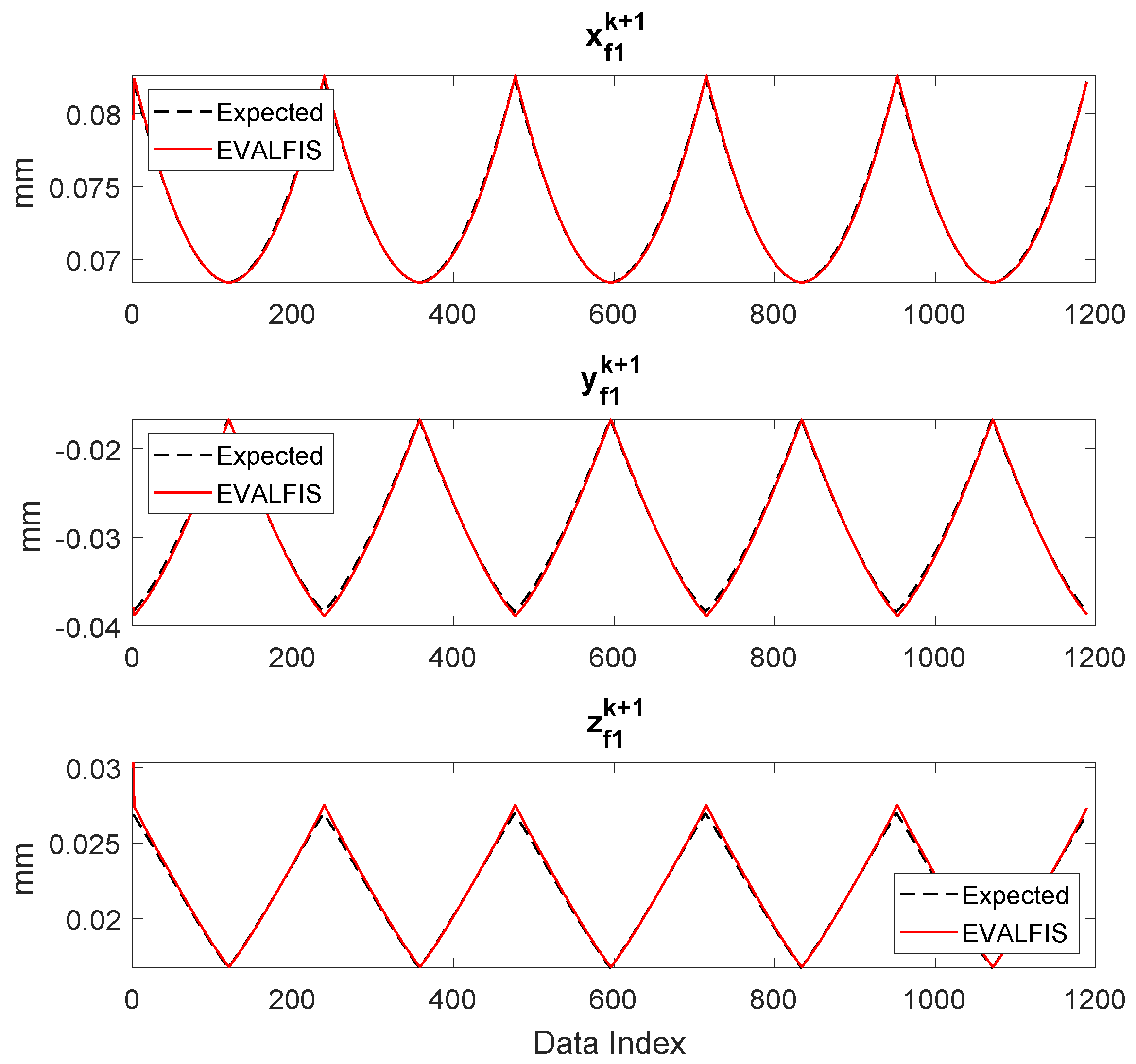
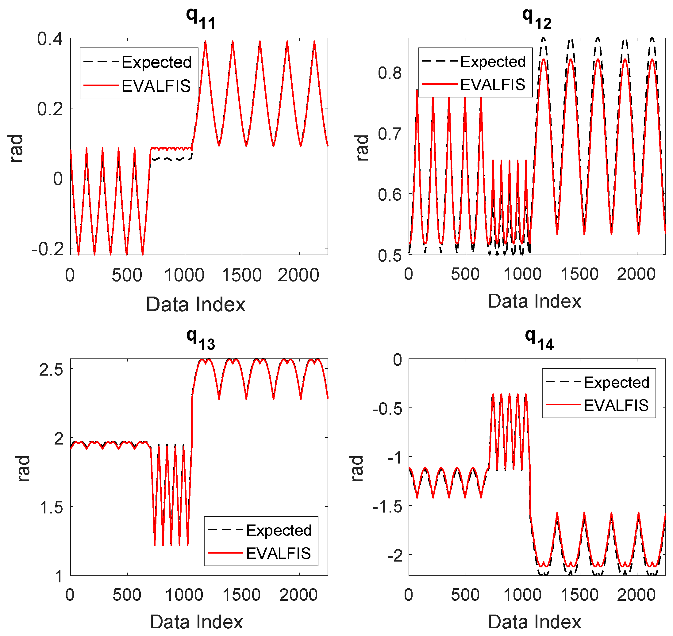
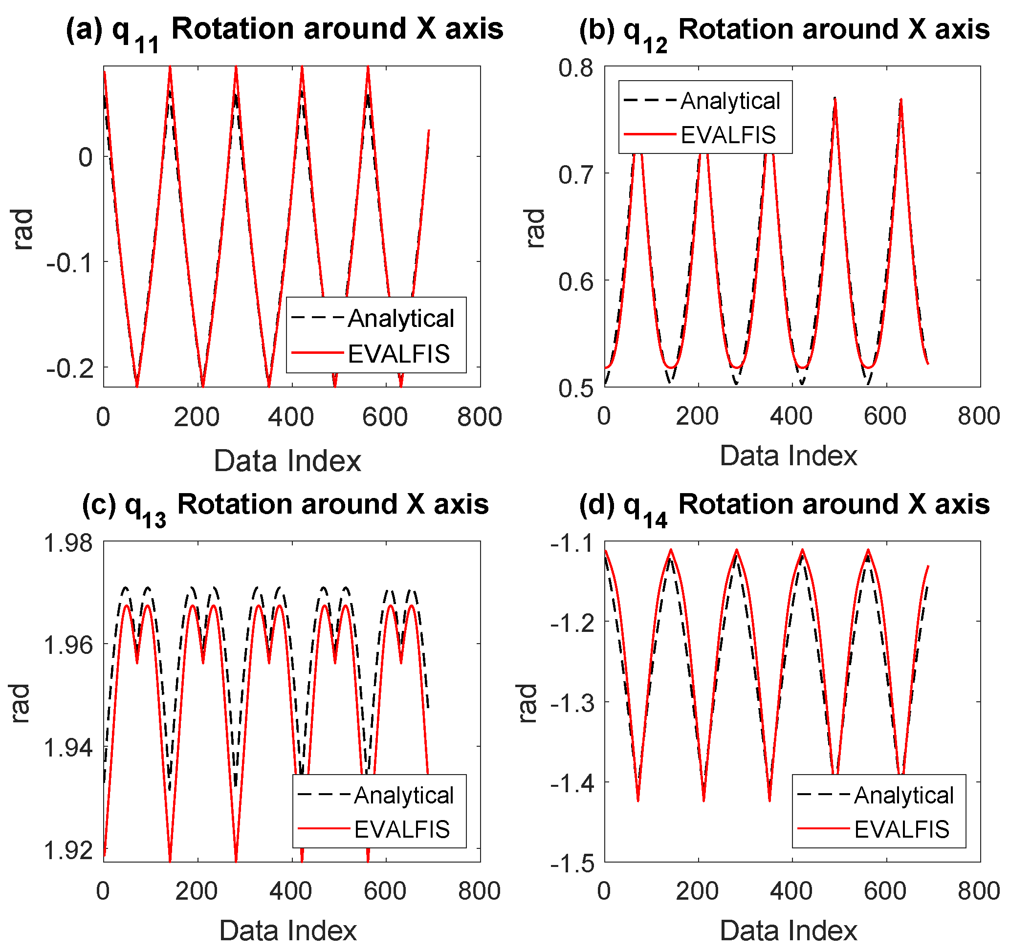
3.4. Validation of the Learned ANFIS Planner in Simulation

Once it is trained, the ANFIS structure must be validated. This is performed in simulation by comparing the output of the ANFIS structure, q i E , with the corresponding actual data, q i , as:
q i E = e v a l f i s O u t f i s ( i j ) , p f i ,
where evalfis is the function to evaluate the fuzzy inference system for input p f i , using the trained ANFIS structure to be evaluated, em Outfis, known as the Sugeno fuzzy inference system (Sugfis), and n d p as the number of data points. The proposed approach is verified through the mean squared error (M.S.E.) method:
M . S . E . ( % ) = 1 n d p k = 1 n d p ( q i E ( k ) q i ( k ) ) 2 × 100

4. Experimental Validation

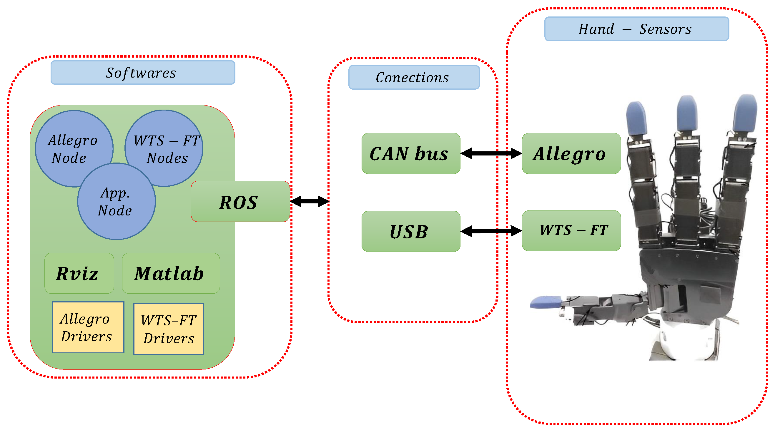
4.1. Hardware Set-Up

We use an Allegro Hand [48] (shown in Figure 5) to do dexterous manipulation. This is an anthropomorphic hand with four fingers, index, middle, ring, and thumb, with four degrees of freedom (DOF) per finger. The first three fingers share the same kinematic structure while the thumb has a different one. The fingers are actuated by DC motors and have potentiometers in the joints to measure their positions with a resolution of 0.002 degrees. The fingertips are equipped with WTS-FT tactile sensors from Weiss Robotics [49]. The Allegro Hand is connected to a PC via a CAN bus, and a robot operating system (ROS) [52] is used as a communication layer to integrate some necessary software modules: a module to control the Allegro Hand with a PID controller and gravity compensation, a module with a graphical user interface to command the movements of each joint of the hand, and a module to perform the object manipulation following the proposed approach. Figure 6 shows the hardware and software set-up.

4.2. Implementation

The system was implemented in MATLAB R2021a running on Linux on a PC equipped with an Intel Core i5 CPU, 16 GB of RAM, a 1 TB hard drive, and an NVIDIA GPU. Rviz is used as a graphical user interface that allows users to interact visually with the robotic systems. Figure 7 shows the applied ANFIS structure of the index finger for manipulation, where the inputs are x f 1 , y f 1 , and z f 1 with two membership functions for each input, a Sugeno-type fuzzy inference system (FIS) with eight rules corresponding to different combinations of membership functions (see Figure 7) and input variables, and the output is a finger joint. The same structure is used for all the joints of all fingers (four structures for each finger and in total 12 for three fingers).
The implemented ANFIS structure also requires:
(a)
A partition of the input space into a grid or fuzzy regions to facilitate the creation of fuzzy rules, overlapping the membership functions, and providing a structured way to represent and model the relationships between input and output variables in a fuzzy system.
(b)
The activation of each fuzzy rule, which is determined as a fuzzy AND operation on the membership values of the input variables associated with that rule.
(c)
The combination of rules which is performed by using a fuzzy OR operation. The OR operation typically involves summing up the contributions of each rule, weighted by its activation level.
(d)
The membership degree to be constrained between 0 and 1.
(e)
The integration of multiple optimization or learning techniques to enhance the training and performance of the ANFIS model, which is known as a hybrid method.
Table 1 summarizes the specification of the ANFIS architecture.

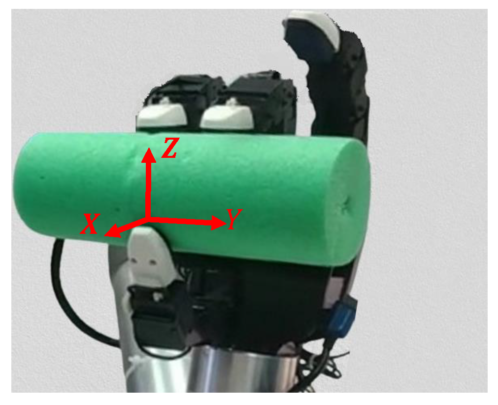
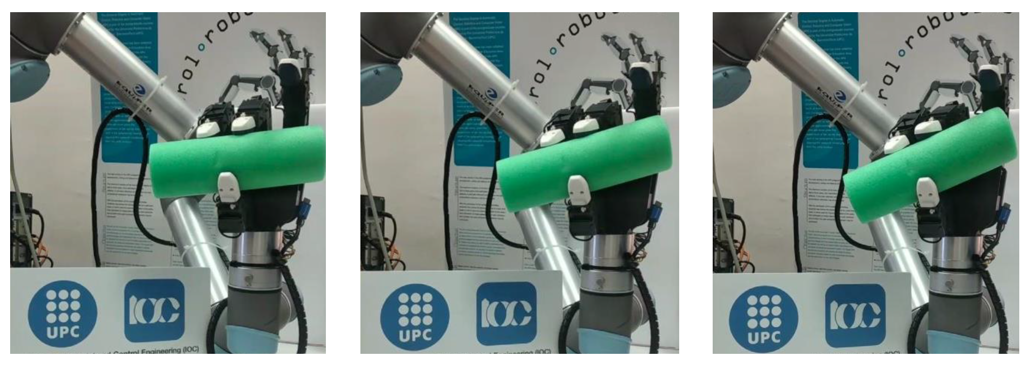
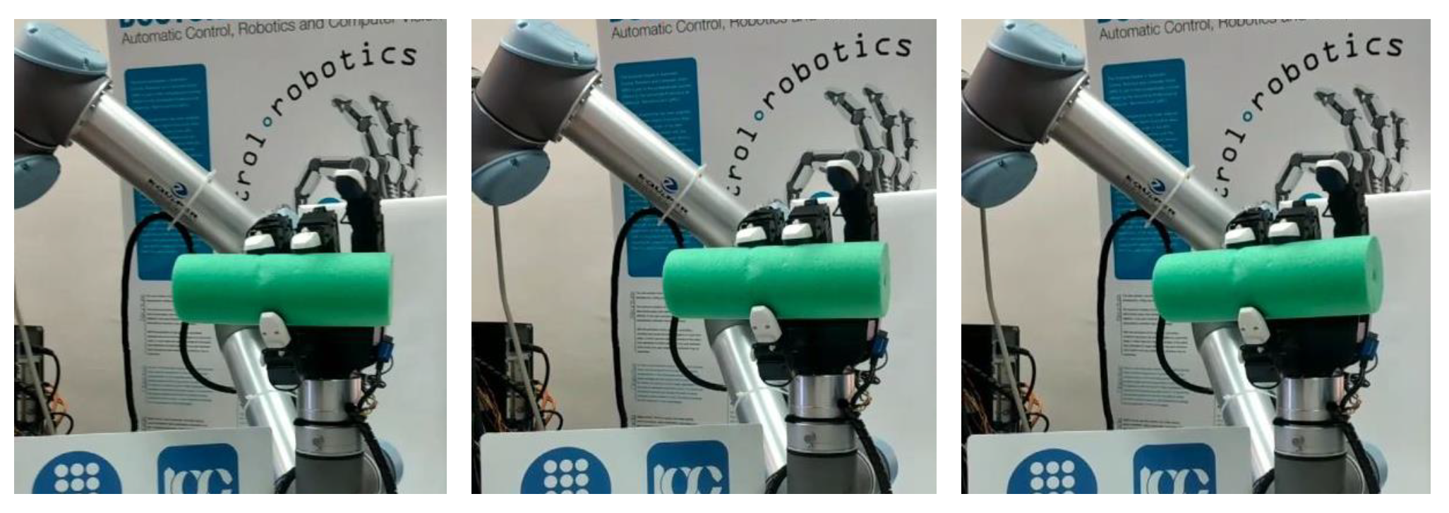
4.3. Description of the Experiment

As mentioned above, in this work, dexterous manipulation is performed using only three fingers: the index ( f 1 ), the thumb ( f 2 ), and the middle finger ( f 3 ), with the thumb working opposite to the other two fingers in the same way that humans do. The desired manipulation is the rotation of the grasped object, forward and backward, around any of the axes, X, Y or Z, with the origin located at the thumb fingertip position, the X-direction perpendicular to the hand palm plate, and the Z-direction parallel to the middle finger when it is fully extended (see Figure 8). The object is unknown, which means that its properties (like shape, weight, and center of mass) are not known during manipulation. The grasping of the object is outside the scope of this work, so it is assumed that the object is already properly grasped before starting the manipulation.
According to the problem statement mentioned in Section 2, focusing on the performance of the ANFIS planner, and avoiding imposing complexity on the system in this specific application, this work is not intended to have any feedback from tactile sensors or any other external sensors.
The set of samples D [ P k Q k ] for training the ANFIS structure was obtained from simulations, fixing different grasping configurations and using a heuristic to move the fingers to rotate the object in the desired direction, in a similar way as was performed in [8]. We generated 15 sequences of hand configurations of about 150 samples each, while manipulating four different objects (i.e., a total of 9000 samples and 60 sequences of hand configurations), and they were filtered using a box whisker plot (Figure 9 illustrates the result for the particular case of the index finger).
After filtering, the outlier data in each sequence are replaced using linear interpolation of neighboring non-outlier values. Table 2 shows same samples for the index finger f 1 . Data from the manipulation of three of the objects (45 sequences of hand configurations containing 6750 samples) are allocated for training and data from the remaining object (15 sequences of the hand configurations containing 2250 samples) are reserved for validation. This allocation ensures that 75% of the samples are utilized for training and 25% are reserved for validation of the system’s performance.
The data set for the training of ANFIS-PP, denoted as D [ P k P k + 1 ] , includes P k , used as the input, and P k + 1 as the output. Subsequently, P k + 1 is used as the input for ANFIS-IK and Q k + 1 as the output. Furthermore, P k + 1 is fed back into ANFIS-PP to compute the positions for the next iteration. It is noteworthy that ANFIS-IK is trained using the data set D S [ P k Q k ] . A schematic of the implemented ANFIS planner is shown in Figure 10. We utilized the ANFIS structure with a hybrid optimization approach and conducted 30 training epochs for both ANFIS-PP and ANFIS-IK.

4.4. Experimental Results

The proposed approach was first validated in simulation. Throughout this simulation, the performance of the trained ANFIS planner is examined in both modules. The ANFIS planner is challenged with a previously unknown scenario, and its output (EVALFIS) is supposed to follow the expected output. The error is calculated during the operation, bearing in mind that the expected output is the output data of the analytical planner that have been processed applying statistical tools. Utilizing Rviz as a graphical user interface, the object was rotated around each of the three axes, X, Y and Z, forward and backward for five times. As an example of system performance, Figure 11 shows the evolution of the index finger next step fingertips x k + 1 , y k + 1 , and z k + 1 in rotation around the Z-axis and Figure 12 depicts the evolution of the index finger joints, q 11 , q 12 , q 13 , and q 14 in rotation around the X-, Y-, and Z-axes, when the system is fed with a set of samples from the test set; the mean square error (MSE) value between the outputs calculated by trained ANFIS and the expected output is shown Table 3. It can be seen that the obtained finger joint values are quite close to the expected values according to the test set. The computational time required by the ANFIS planner in each iteration during the experiment is shown in Figure 13. Under identical conditions, the average computational time for the ANFIS planner is 4.8 ± 0.08 ms and for the analytical planner is 1.0 ± 0.08 ms. Even though the ANFIS planner is slower, it is still fast enough for real-time execution.
After the simulations, the system was tested in a real-world experiment using the real Allegro Hand. The experimental scenario is the same as that used in simulation, and the ANFIS and analytical planner outputs are compared under identical operational conditions. This real-world experiment was executed by initiating the MATLAB code to establish a connection with ROS as a publisher. This enables real-time data exchange with the other connected components. This includes:
  • Selecting the desired rotation axis, X, Y, or Z, by operator.
  • Selecting ϕ d e s i r e d (the desired rotation angle illustrated in Figure 2) by operator. The maximum rotational angles empirically achieved in our experiment around the X-, Y- or Z-axes were 35, 18, and 60 degrees, respectively.
  • Defining Δ ϕ (which is the rotation step) equal to 0.5 degree (see Figure 2).
  • Importing initial fingertips point position from RVIZ.
  • Defining the desired number of rotation cycles.
  • Executing the MATLAB code.
Figure 14, Figure 15 and Figure 16 show images of the experiment in the real setup for rotation of the unkhown object around the X-, Y-, and Z-axes, respectively. A video of the experiment is available at youtube.com/IOC Robotics Lab (accessed on 21 May 2024). It is worth noting that, due to the kinematic structure of the hand, depending on the hand configuration, certain motions have a more limited range than others. This is what happens to the rotation of an unknown object around the Z-axis in comparison to the other axes, creating the appearance of slower movements.
As an example of system performance in the real-world experiment, Figure 17 shows a comparison of the ANFIS and analytical planner outputs for the index finger joints, q 11 , q 12 , q 13 , and q 14 during rotation around the X-axis, under identical conditions. It can be noticed that the planner outputs are relatively similar to each other; however, the ANFIS planner attempts to do the task more smoothly.

5. Conclusions

In this paper, we present a learning-based approach, based on ANFIS, to address in-hand manipulation in real-world scenarios, producing satisfactory operational outcomes. This method provides the robots with the ability to learn from data, significantly reducing their reliance on precise and complex mathematical models for planning and execution in dexterous manipulation. The transition to data-driven learning enables the robots to respond to a wider range of situations and uncertainties present in real-world environments more effectively, providing a more adaptable and reliable method for performing intricate manipulation tasks. For future work, incorporating tactile sensor data to reach force control, exploring alternative learning methods, extension of the approach to rotate unknown objects around any desired axes, and applying four fingers in manipulation will be considered. Furthermore, we plan to merge the two “learning modules” described in this work (ANFIS-PP and ANFIS-IK) into a single one, learning directly the proper joint movements for manipulation without the need for learning, on the one side, the fingertip movements, and, then, on the other side, computing the IK (either analytically or using a learning approach).

Author Contributions

Conceptualization, M.S.; Methodology, M.S., R.S. and J.R.; Software, M.S.; Validation, M.S.; Investigation, M.S., R.S. and J.R.; Writing—original draft, M.S.; Writing—review & editing, R.S. and J.R.; Supervision, R.S. and J.R.; Funding acquisition, R.S. and J.R. All authors have read and agreed to the published version of the manuscript.

Funding

This work was partially supported by the Spanish Government through the project PID2020-114819GB-I00.

Data Availability Statement

The comprehensive data set pertinent to the project is available through the link: gitioc.upc.edu/Data (accessed on 21 May 2024).

Acknowledgments

The authors would like to thank Morad Shirzadi Maryan for his work on the data generator code and Leopold Palomo Avellaneda for his contribution in configuring the software and hardware setup of the mechanical hand.

Conflicts of Interest

The authors declare no conflicts of interest.

References

  1. Ceccarelli, M.; Ceccarelli, M. Fundamentals of the Mechanics of Robots; Springer: Berlin/Heidelberg, Germany, 2004. [Google Scholar]
  2. Bicchi, A. Hands for dexterous manipulation and robust grasping: A difficult road toward simplicity. IEEE Trans. Robot. Autom. 2000, 16, 652–662. [Google Scholar] [CrossRef]
  3. Siciliano, B.; Khatib, O.; Kröger, T. Springer Handbook of Robotics; Springer: Berlin/Heidelberg, Germany, 2008; Volume 200. [Google Scholar]
  4. Rus, D. In-hand dexterous manipulation of piecewise-smooth 3-d objects. Int. J. Robot. Res. 1999, 18, 355–381. [Google Scholar] [CrossRef]
  5. Andrews, S.; Kry, P.G. Goal directed multi-finger manipulation: Control policies and analysis. Comput. Graph. 2013, 37, 830–839. [Google Scholar] [CrossRef]
  6. Dafle, N.C.; Rodriguez, A.; Paolini, R.; Tang, B.; Srinivasa, S.S.; Erdmann, M.; Mason, M.T.; Lundberg, I.; Staab, H.; Fuhlbrigge, T. Extrinsic dexterity: In-hand manipulation with external forces. In Proceedings of the 2014 IEEE International Conference on Robotics and Automation (ICRA), Hong Kong, China, 31 May–7 June 2014; pp. 1578–1585. [Google Scholar]
  7. Bai, Y.; Liu, C.K. Dexterous manipulation using both palm and fingers. In Proceedings of the 2014 IEEE International Conference on Robotics and Automation (ICRA), Hong Kong, China, 31 May–7 June 2014; pp. 1560–1565. [Google Scholar]
  8. Montaño, A.; Suárez, R. Dexterous manipulation of unknown objects using virtual contact points. Robotics 2019, 8, 86. [Google Scholar] [CrossRef]
  9. Han, L.; Trinkle, J. Dextrous manipulation by rolling and finger gaiting. In Proceedings of the 1998 IEEE International Conference on Robotics and Automation (Cat. No.98CH36146), Leuven, Belgium, 20 May 1998; Volume 1, pp. 730–735. [Google Scholar] [CrossRef]
  10. Funabashi, S.; Schmitz, A.; Sato, T.; Somlor, S.; Sugano, S. Robust in-hand manipulation of variously sized and shaped objects. In Proceedings of the 2015 IEEE/RSJ International Conference on Intelligent Robots and Systems (IROS), Hamburg, Germany, 28 September–2 October 2015; pp. 257–263. [Google Scholar] [CrossRef]
  11. Liarokapis, M.; Dollar, A.M. Deriving dexterous, in-hand manipulation primitives for adaptive robot hands. In Proceedings of the 2017 IEEE/RSJ International Conference on Intelligent Robots and Systems (IROS), Vancouver, BC, Canada, 24–28 September 2017; pp. 1951–1958. [Google Scholar] [CrossRef]
  12. Hong, J.; Lafferriere, G.; Mishra, B.; Tan, X. Fine manipulation with multifinger hands. In Proceedings of the IEEE International Conference on Robotics and Automation, Cincinnati, OH, USA, 13–18 May 1990; Volume 3, pp. 1568–1573. [Google Scholar] [CrossRef]
  13. Goodwine, B.; Burdick, J. Motion planning for kinematic stratified systems with application to quasi-static legged locomotion and finger gaiting. IEEE Trans. Robot. Autom. 2002, 18, 209–222. [Google Scholar] [CrossRef]
  14. Montaño, A.; Suárez, R. Improving grasping forces during the manipulation of unknown objects. In Proceedings of the 2018 IEEE/RSJ International Conference on Intelligent Robots and Systems (IROS), Madrid, Spain, 1–5 October 2018; pp. 3490–3495. [Google Scholar]
  15. Montaño, A.; Suárez, R. Manipulation of unknown objects to improve the grasp quality using tactile information. Sensors 2018, 18, 1412. [Google Scholar] [CrossRef] [PubMed]
  16. Lepert, M.; Pan, C.; Yuan, S.; Antonova, R.; Bohg, J. In-Hand Manipulation of Unknown Objects with Tactile Sensing for Insertion. In Proceedings of the Embracing Contacts-Workshop at ICRA 2023, London, UK, 2 June 2023. [Google Scholar]
  17. Tian, H.; Song, K.; Li, S.; Ma, S.; Xu, J.; Yan, Y. Data-driven robotic visual grasping detection for unknown objects: A problem-oriented review. Expert Syst. Appl. 2023, 211, 118624. [Google Scholar] [CrossRef]
  18. Montaño, A.; Suárez, R. Commanding the object orientation using dexterous manipulation. In Robot 2015: Second Iberian Robotics Conference; Springer: Berlin/Heidelberg, Germany, 2016; pp. 69–79. [Google Scholar]
  19. Kroemer, O.; Leischnig, S.; Luettgen, S.; Peters, J. A kernel-based approach to learning contact distributions for robot manipulation tasks. Auton. Robot. 2018, 42, 581–600. [Google Scholar] [CrossRef]
  20. Jiang, Y.; Lim, M.; Zheng, C.; Saxena, A. Learning to place new objects in a scene. Int. J. Robot. Res. 2012, 31, 1021–1043. [Google Scholar] [CrossRef]
  21. Sturm, J.; Jain, A.; Stachniss, C.; Kemp, C.C.; Burgard, W. Operating articulated objects based on experience. In Proceedings of the 2010 IEEE/RSJ International Conference on Intelligent Robots and Systems, Taipei, Taiwan, 18–22 October 2010; pp. 2739–2744. [Google Scholar]
  22. Lenz, I.; Lee, H.; Saxena, A. Deep learning for detecting robotic grasps. Int. J. Robot. Res. 2015, 34, 705–724. [Google Scholar] [CrossRef]
  23. Schenck, C.; Tompson, J.; Levine, S.; Fox, D. Learning robotic manipulation of granular media. In Proceedings of the Conference on Robot Learning, PMLR, Mountain View, CA, USA, 13–15 November 2017; pp. 239–248. [Google Scholar]
  24. Konidaris, G.; Kaelbling, L.P.; Lozano-Perez, T. From skills to symbols: Learning symbolic representations for abstract high-level planning. J. Artif. Intell. Res. 2018, 61, 215–289. [Google Scholar] [CrossRef]
  25. Andrychowicz, O.M.; Baker, B.; Chociej, M.; Jozefowicz, R.; McGrew, B.; Pachocki, J.; Petron, A.; Plappert, M.; Powell, G.; Ray, A.; et al. Learning dexterous in-hand manipulation. Int. J. Robot. Res. 2020, 39, 3–20. [Google Scholar] [CrossRef]
  26. Schlagenhauf, C.; Bauer, D.; Chang, K.H.; King, J.P.; Moro, D.; Coros, S.; Pollard, N. Control of tendon-driven soft foam robot hands. In Proceedings of the 2018 IEEE-RAS 18th International Conference on Humanoid Robots (Humanoids), Beijing, China, 6–9 November 2018; pp. 1–7. [Google Scholar]
  27. Ren, T.; Dong, Y.; Wu, D.; Chen, K. Learning-based variable compliance control for robotic assembly. J. Mech. Robot. 2018, 10, 061008. [Google Scholar] [CrossRef]
  28. Detry, R.; Kraft, D.; Kroemer, O.; Bodenhagen, L.; Peters, J.; Krüger, N.; Piater, J. Learning grasp affordance densities. Paladyn 2011, 2, 1–17. [Google Scholar] [CrossRef]
  29. Hjelm, M.; Detry, R.; Ek, C.H.; Kragic, D. Representations for cross-task, cross-object grasp transfer. In Proceedings of the 2014 IEEE International Conference on Robotics and Automation (ICRA), Hong Kong, China, 31 May–7 June 2014; pp. 5699–5704. [Google Scholar]
  30. Lu, Q.; Hermans, T. Modeling grasp type improves learning-based grasp planning. IEEE Robot. Autom. Lett. 2019, 4, 784–791. [Google Scholar] [CrossRef]
  31. Konidaris, G.; Kuindersma, S.; Grupen, R.; Barto, A. Autonomous skill acquisition on a mobile manipulator. In Proceedings of the AAAI Conference on Artificial Intelligence, San Francisco, CA, USA, 7–11 August 2011; Volume 25, pp. 1468–1473. [Google Scholar]
  32. Juett, J.; Kuipers, B. Learning to grasp by extending the peri-personal space graph. In Proceedings of the 2018 IEEE/RSJ International Conference on Intelligent Robots and Systems (IROS), Madrid, Spain, 1–5 October 2018; pp. 8695–8700. [Google Scholar]
  33. Su, Z.; Kroemer, O.; Loeb, G.E.; Sukhatme, G.S.; Schaal, S. Learning to switch between sensorimotor primitives using multimodal haptic signals. In Proceedings of the From Animals to Animats 14: 14th International Conference on Simulation of Adaptive Behavior, SAB 2016, Aberystwyth, UK, 23–26 August 2016; Proceedings 14. Springer: Berlin/Heidelberg, Germany, 2016; pp. 170–182. [Google Scholar]
  34. Arunachalam, S.P.; Silwal, S.; Evans, B.; Pinto, L. Dexterous imitation made easy: A learning-based framework for efficient dexterous manipulation. In Proceedings of the 2023 IEEE International Conference on Robotics and Automation (ICRA), London, UK, 29 May–2 June 2023; pp. 5954–5961. [Google Scholar]
  35. Kumar, V.; Todorov, E.; Levine, S. Optimal control with learned local models: Application to dexterous manipulation. In Proceedings of the 2016 IEEE International Conference on Robotics and Automation (ICRA), Stockholm, Sweden, 16–21 May 2016; pp. 378–383. [Google Scholar]
  36. Li, M.; Yin, H.; Tahara, K.; Billard, A. Learning object-level impedance control for robust grasping and dexterous manipulation. In Proceedings of the 2014 IEEE International Conference on Robotics and Automation (ICRA), Hong Kong, China, 31 May–7 June 2014; pp. 6784–6791. [Google Scholar]
  37. Gupta, A.; Eppner, C.; Levine, S.; Abbeel, P. Learning dexterous manipulation for a soft robotic hand from human demonstrations. In Proceedings of the 2016 IEEE/RSJ International Conference on Intelligent Robots and Systems (IROS), Daejeon, Republic of Korea, 9–14 October 2016; pp. 3786–3793. [Google Scholar]
  38. Jang, J.S. ANFIS: Adaptive-network-based fuzzy inference system. IEEE Trans. Syst. Man Cybern. 1993, 23, 665–685. [Google Scholar] [CrossRef]
  39. Patel, D.; Cohen, K. Obstacle Avoidance and Target Tracking by Two Wheeled Differential Drive Mobile Robot Using ANFIS in Static and Dynamic Environment. In Fuzzy Information Processing 2020: Proceedings of the 2020 Annual Conference of the North American Fuzzy Information Processing Society, NAFIPS 2020; Springer: Berlin/Heidelberg, Germany, 2022; pp. 337–348. [Google Scholar]
  40. Pandey, A.; Kumar, S.; Pandey, K.K.; Parhi, D.R. Mobile robot navigation in unknown static environments using ANFIS controller. Perspect. Sci. 2016, 8, 421–423. [Google Scholar] [CrossRef]
  41. Pandey, A.; Kashyap, A.K.; Parhi, D.R.; Patle, B. Autonomous mobile robot navigation between static and dynamic obstacles using multiple ANFIS architecture. World J. Eng. 2019, 16, 275–286. [Google Scholar] [CrossRef]
  42. Fan, S.; Liu, Y.; Wu, K.; Chen, Z.; Jiang, Z.; Jiang, L.; Liu, H. Object shape recognition and grasping by five-fingered robotic hand based on E-ANFIS model. In Proceedings of the 2009 IEEE International Conference on Robotics and Biomimetics (ROBIO), Guilin, China, 19–23 December 2009; pp. 1075–1080. [Google Scholar]
  43. Keskin, C.; Kıraç, F.; Kara, Y.E.; Akarun, L. Real time hand pose estimation using depth sensors. In Consumer Depth Cameras for Computer Vision: Research Topics and Applications; Springer: Berlin/Heidelberg, Germany, 2013; pp. 119–137. [Google Scholar]
  44. Ma, Y.; Mao, Z.H.; Jia, W.; Li, C.; Yang, J.; Sun, M. Magnetic hand tracking for human-computer interface. IEEE Trans. Magn. 2011, 47, 970–973. [Google Scholar] [CrossRef]
  45. Meattini, R.; Suárez, R.; Palli, G.; Melchiorri, C. Human to Robot Hand Motion Mapping Methods: Review and Classification. IEEE Trans. Robot. 2022, 39, 842–861. [Google Scholar] [CrossRef]
  46. Gioioso, G.; Salvietti, G.; Malvezzi, M.; Prattichizzo, D. Mapping Synergies From Human to Robotic Hands With Dissimilar Kinematics: An Approach in the Object Domain. IEEE Trans. Robot. 2013, 29, 825–837. [Google Scholar] [CrossRef]
  47. Salvietti, G.; Malvezzi, M.; Gioioso, G.; Prattichizzo, D. On the use of homogeneous transformations to map human hand movements onto robotic hands. In Proceedings of the 2014 IEEE International Conference on Robotics and Automation (ICRA), Hong Kong, China, 31 May–7 June 2014; pp. 5352–5357. [Google Scholar]
  48. Allegro Robotic Hand—Wonik Robotics. Available online: https://www.wonikrobotics.com/en/robot-hand (accessed on 21 November 2023).
  49. WTS-FT—Weiss Robotics GmbH & Co. Available online: https://weiss-robotics.com/company/ (accessed on 10 August 2019).
  50. Feix, T.; Romero, J.; Schmiedmayer, H.B.; Dollar, A.M.; Kragic, D. The grasp taxonomy of human grasp types. IEEE Trans. Hum.-Mach. Syst. 2015, 46, 66–77. [Google Scholar] [CrossRef]
  51. Chen, Y.S.; Hung, Y.H.; Lee, M.Y.J.; Lai, C.J.; Chang, J.R.; Chien, C.Y. Identification of the Yield Rate by a Hybrid Fuzzy Control PID-Based Four-Stage Model: A Case Study of Optical Filter Industry. Axioms 2024, 13, 54. [Google Scholar] [CrossRef]
  52. Quigley, M.; Gerkeyy, B.; Conleyy, K.; Fausty, J.; Footey, T.; Leibsz, J.; Bergery, E.; Wheelery, R.; Ng, A. ROS: An open-source Robot Operating System. In Proceedings of the ICRA Workshop on Open Source Software, Kobe, Japan, 12–17 May 2009; Volume 3, p. 5. [Google Scholar]
Figure 1. System schematic diagram applying a conventional planner.
Machines 12 00364 g001
Figure 2. System schematic diagram applying the ANFIS planner.
Machines 12 00364 g002
Figure 3. ANFIS architecture consists of three input parameters p f i = [ x f i y f i z f i ] , and eight fuzzy rules.
Machines 12 00364 g003
Figure 4. Schematic illustration of generalized Gaussian bell membership functions and parameters.
Machines 12 00364 g004
Figure 5. Anthropomorphic robotic hand Allegro Hand [48], with 16 degrees of freedom (DOF) and 4 fingertips with tactile sensors WTS-FT [8,49].
Machines 12 00364 g005
Figure 6. Experiment setup overview: The Allegro Hand is connected to a PC with a CAN bus and WTS-FT sensors at the fingertips with a USB port. All the software components are integrated using a robotic operative system (ROS) as the communications layer. The nodes are modular components in the ROS architecture that perform specific tasks and the drivers are the software component that facilitates communication between the ROS and a specific hardware device.
Machines 12 00364 g006
Figure 7. Representation of the ANFIS structure using the Matlab Neuro-Fuzzy Designer toolbox. The input is p f i , and the membership functions are introduced in Equation (1).
Machines 12 00364 g007
Figure 8. Illustration of the rotation axes during the experiment.
Machines 12 00364 g008
Figure 9. Box whisker plot for the set of training samples for f 1 that confirms the absence of outlier data in x f 1 , z f 1 , q 11 , q 12 , q 13 and finds the outlier data in y f 1 and q 14 (represented with a cycle).
Machines 12 00364 g009
Figure 10. Schematic of ANFIS planner internal structure.
Machines 12 00364 g010
Figure 11. Comparison of ANFIS-PP output (EVALFIS) versus expected output for index fingertip positions in rotation around the Z-axis for 5 forward and backward rotations, with each forward and backward rotation having about 237 data points (i.e., data indexes from 0 to 237 show the first forward and backward rotation).
Machines 12 00364 g011
Figure 12. Comparisonof ANFIS-IK output (EVALFIS) versus expected output for index finger joints in rotation around the X- (data indexes 0 to 690), Y- (data indexes 690 to 1060), and Z- (data indexes 1060 to 2250) axes.
Machines 12 00364 g012
Figure 13. Computational time required by the ANFIS planner in each iteration during the experiment. The red dashed line represent fitted curve shows the second order regression to illustrate a simplified representation of the data.
Machines 12 00364 g013
Figure 14. Experiment for manipulation of unknown objects around the X-axis.
Machines 12 00364 g014
Figure 15. Experiment for manipulation of unknown objects around the Y-axis.
Machines 12 00364 g015
Figure 16. Experiment for manipulation of unknown objects around the Z-axis.
Machines 12 00364 g016
Figure 17. Comparison of ANFIS planner output (EVALFIS) versus analytical planner output for index finger joints in rotation around the X-axis for 5 forward and backward in real-world experiment. A forward and backward rotation has 138 samples (i.e., data indexes 0 to 138 show the first forward and backward rotation around the X-axis).
Machines 12 00364 g017
Table 1. Specification of the ANFIS architecture.
NameType
Generate FIS typeSugeno
The initial FIS modelGrid partition
Decision method for fuzzy logic operation AND (minimum)Product
Decision method for fuzzy logic operation OR (maximum)Probabilistic
Output defuzzification methodWeighted average
Number of membership functions for x f i 2
Number of membership functions for y f i 2
Number of membership functions for z f i 2
Input membership function typeGaussian bell
Output membership function typeConstant type
Number of rules8
Train FIS optimization methodHybrid
Number of epochs30
Table 2. Some elements of the sample data set for the index finger, f 1 .
x f 1 y f 1 z f 1 q 11 q 12 q 13 q 14
10.09363−0.030900.030660.162500.530361.91182−1.12669
20.09363−0.030900.030660.158100.529581.91366−1.12774
30.09363−0.031320.030610.153690.528871.91548−1.12886
9000
Table 3. Mean square error value between the outputs calculated by trained ANFIS and the expected output for f 1 . MSE units for ANFIS-PP and ANFIS-IK are, respectively, in mm2 and rad2.
ANFIS-PPANFIS-IK
Output x f 1 y f 1 z f 1 q 11 q 12 q 13 q 14
MSE 2.8 × 10 8 1.0 × 10 7 5.1 × 10 8 1.8 × 10 4 1.8 × 10 4 1.8 × 10 4 1.8 × 10 4
Disclaimer/Publisher’s Note: The statements, opinions and data contained in all publications are solely those of the individual author(s) and contributor(s) and not of MDPI and/or the editor(s). MDPI and/or the editor(s) disclaim responsibility for any injury to people or property resulting from any ideas, methods, instructions or products referred to in the content.

