Article

A Robust Online Diagnostic Strategy of Inverter Open-Circuit Faults for Robotic Joint BLDC Motors †

by
Mohamed Y. Metwly
,
Victor M. Logan
,
Charles L. Clark
,
Jiangbiao He
* and
Biyun Xie
Department of Electrical and Computer Engineering, University of Kentucky, Lexington, KY 40506, USA
*
Author to whom correspondence should be addressed.
This paper is an extended version of our paper published in 2024 IEEE Applied Power Electronics Conference and Exposition (APEC), Long Beach, CA, USA, 25–29 February 2024; pp. 2308–2313. https://doi.org/10.1109/APEC48139.2024.10509158.
Machines 2024, 12(7), 430; https://doi.org/10.3390/machines12070430
Submission received: 23 May 2024 / Revised: 16 June 2024 / Accepted: 20 June 2024 / Published: 24 June 2024

Abstract

:
As robots are increasingly used in remote, safety-critical, and hazardous applications, the reliability of robots is becoming more important than ever before. Robotic arm joint motor-drive systems are vulnerable to hardware failures due to harsh operating environment in many scenarios, which may yield various joint failures and result in significant downtime costs. Targeting the most common robotic joint brushless DC (BLDC) motor-drive systems, this paper proposes a robust online diagnostic method for semiconductor faults for BLDC motor drives. The proposed fault diagnostic technique is based on the stator current signature analysis. Specifically, this paper investigates the performance of the BLDC joint motors under open-circuit faults of the inverter switches using finite element co-simulation tools. Furthermore, the proposed methodology is not only capable of detecting any open-circuit faults but also identifying faulty switches based on a knowledge table by considering various fault conditions. The robustness of the proposed technique was verified through extensive simulations under different speed and load conditions. Moreover, simulations have been carried out on a Kinova Gen-3 robot arm to verify the theoretical findings, highlighting the impacts of locked joints on the robot’s end-effector locations. Finally, experimental results are presented to corroborate the performance of the proposed fault diagnostic strategy.

1. Introduction

Harsh environments with extreme temperature, humidity, radiation, etc., escalate the possibility of hardware failures of robotic actuators [1]. In many safety-critical, remote, and dangerous environments, such as space exploration [2], nuclear waste remediation [3], and disaster rescue [4], not only are failures more likely to occur, but also it is impossible to perform routine maintenance for these robots. Besides the above situations, failures that occur in safety-critical applications, such as robotic surgery [5], rehabilitation [6], and human–robot interaction [7], could also lead to catastrophic consequences. It is worth mentioning that one common fault contributing to frequent robot joint failures occurs in the joint motor drives, especially in power inverters consisting of numerous semiconductor transistors which are generally sensitive to the variations of temperature, radiation, air pressure, humidity, and radiation. Particularly, for robots used in heavy-duty harsh environments, the semiconductor switches in the joint motor drives can suffer from aging faults and subsequent switching failures, eventually leading to the malfunction of the entire robot joint and automation systems. From a robotic arm perspective, the most frequent failures are locked joint failures [8,9]. Thus, robotic arms for the above-mentioned applications must possess the ability to perform ”fail-active” operation, i.e., autonomous continued operation in the presence of unpredictable failures and degradation after failures.
Brushless DC (BLDC) motors have been intensively utilized in robotic arms due to their inherent merits, e.g., high reliability, high efficiency, and low maintenance costs. There are many references in the literature reporting the design of robotic joint motors or inverters, but little attention has been given to their health monitoring and reliability improvements. For instance, in [10], a three-phase electromagnetic actuator has been designed for robotic applications using a BLDC motor. The proposed design optimization technique aims at improving the machine response, considering the torque-to-inertia and torque-to-weight ratios as the main optimization objectives. Additionally, the Kinova Gen-3 robot arm, a well-known, extremely versatile and portable robotic arm with six DoF (degrees of freedom) configurations, which will be investigated and tested in this work, uses seven BLDC joint motors, as depicted in Figure 1. Therefore, a robotic BLDC motor-drive system will be focused on in this research.
For BLDC motor-drive systems used in robotic arms, semiconductor open-circuit and short-circuit failures are prevalent in BLDC motor drives, resulting in the low reliability of robots, especially for applications in harsh environments. The detection of semiconductor short-circuit switching faults has been well implemented in most of the commercial inverter gate drivers, but the diagnosis of open-circuit switching faults has received insufficient attention. In fact, open-circuit faults may easily yield secondary damage if not quickly detected, due to significantly unbalanced voltages and currents, uncontrollable speed and torque profiles, as well as increased motor torque oscillations, when an open-circuit switching fault occurs to the BLDC motor drives. Therefore, it is crucial to detect and identify faulty phases and switches as fast as possible. A robust inverter fault diagnosis is paramount to enhance the reliability and decrease the downtime cost of robotic arms, which will be the main focus of this paper.
In the recent literature, several open-circuit fault diagnosis techniques have been presented for both two-level and multilevel inverters [11,12]. Fault diagnosis and identification strategies have been investigated for IGBT or MOSFET open-circuit failures, shedding light on line voltages or current measurements. Fault diagnostic methods are classified into signal extraction, model-based, and knowledge-based techniques. The signal extraction methods are further categorized into voltage and current signal extraction diagnoses [13]. Fast fault detection methods are proposed based on the voltage signal analysis with additional voltage acquisition circuitry. On the contrary, simple and low-cost fault diagnosis techniques are implemented based on the current signal extraction. Fault detection based on signal analysis is performed by comparing the measured motor performances with optimal conditions. In [14], an enhanced current distortion technique was proposed for multilevel inverter open-switch fault diagnosis. Besides the fault diagnosis capability, the proposed technique is capable of identifying the faulty switches by measuring the current distortion in each phase and DC-link voltage variations and utilizing look-up tables. Subsequently, open-circuit faults in multilevel hybrid active neutral point converters (HANPC) are efficiently diagnosed and localized. A fast inverter open-circuit fault diagnosis technique was recently introduced using topology for current path detection of BLDC motors [13]. In that case, the inverter faults are identified and located based on the current path detection and current path change, respectively. The proposed fault detection method offers numerous advantages, such as fast fault diagnosis and less effect by sudden load changes.
Moreover, an inverter open-circuit fault is detected based on the comparison of the actual outputs of the proposed model with its theoretical outputs when model-based diagnosis techniques are used. In [15], a fault detection strategy was presented for inverter open-switch faults in permanent magnet synchronous machine (PMSM) drives. The proposed technique utilizes an efficient approach based on cost function error with model predictive current control (MPCC). In this case, the fault is localized by investigating the error between the estimated cost function and the actual one. The proposed approach is robust to the variations in operating conditions and motor parameters. Model-based fault detection methods entail no extra hardware; however, the accuracy of the fault detection mainly depends on the parameter estimation and accuracy of the model. Lastly, fuzzy logic or neural networks are used in knowledge-based inverter fault diagnosis techniques for motor drives, taking advantage of the full knowledge of the system. For example, a fuzzy-based fault detection technique for PMSM drives has been presented using the motor current Park’s vector representation [16]. The inverter open-circuit faults that can be detected and localized by the proposed fault detection approach include single, multiple, and intermittent failures. Some systems take full advantage of using two different fault detection techniques.
Various fault detection techniques leverage the benefits of co-simulation tools for motor-drive applications, including inverter switch fault diagnosis [17,18,19]. In [17], the modeling of high-performance multiphase brushless AC (BLAC) machines was investigated for aerospace applications using Simulink and Ansys Twin Builder co-simulation models. The accuracy of the proposed co-simulation model has been proven by simulations for motor-drive systems. Another recent co-simulation model was introduced for PMSM-based electric vehicles (EVs) [18]. This paper used Ansys software and Simulink to analyze the PMSM drive system under various reference speeds, which further shows the effectiveness of using co-simulation of the electrical and magnetic domains to highlight all possible effects. Moreover, a co-simulation approach has been used for vibration spectrum-based fault diagnosis of BLDC motor drives [19]. Based on the vibration spectrum obtained under healthy and faulty cases, the rotor PM demagnetization fault can be diagnosed. It is worth mentioning that several fault detection techniques have been recently proposed for sine-wave drives [20,21,22], which can be applied to square-wave drives. The main drawbacks of existing fault diagnosis techniques—besides complexity and false alarms—are the high cost of implementation and lack of robustness.
This paper proposes a robust online fault detection methodology for BLDC motor drives with switch open-circuit failures, which outperforms conventional fault diagnosis techniques that are not robust against variations in speed and load conditions. The benefits of employing a knowledge-based table for fault identification and current signal analysis for fault detection are combined in the proposed fault detection technique using the discrete Fourier transform (DFT) analysis of the stator currents. Particularly, in the motor-drive co-simulation studies, Ansys Electronics Desktop is used to achieve the optimal design of the BLDC motor for robotic applications. Ansys Twin Builder is used to construct the two-level three-phase inverter, while Simulink is used to implement the BLDC motor control. Furthermore, a comparison of the proposed fault detection technique with the ones presented in the literature is presented, as listed in Table 1. These fault diagnosis methods are compared considering the motor type, diagnosis technique, fault identification capability, complexity, and whether robustness analysis is included or not. The main contributions of this study are summarized as follows:
  • Development of a robust online inverter switch open-circuit fault diagnosis and identification technique.
  • Finite element analysis (FEA) co-simulation results verify the efficacy of the proposed fault diagnosis technique using an optimally designed BLDC motor for robotic arms.
  • Robustness analysis of the proposed detection method under various speed and load scenarios.
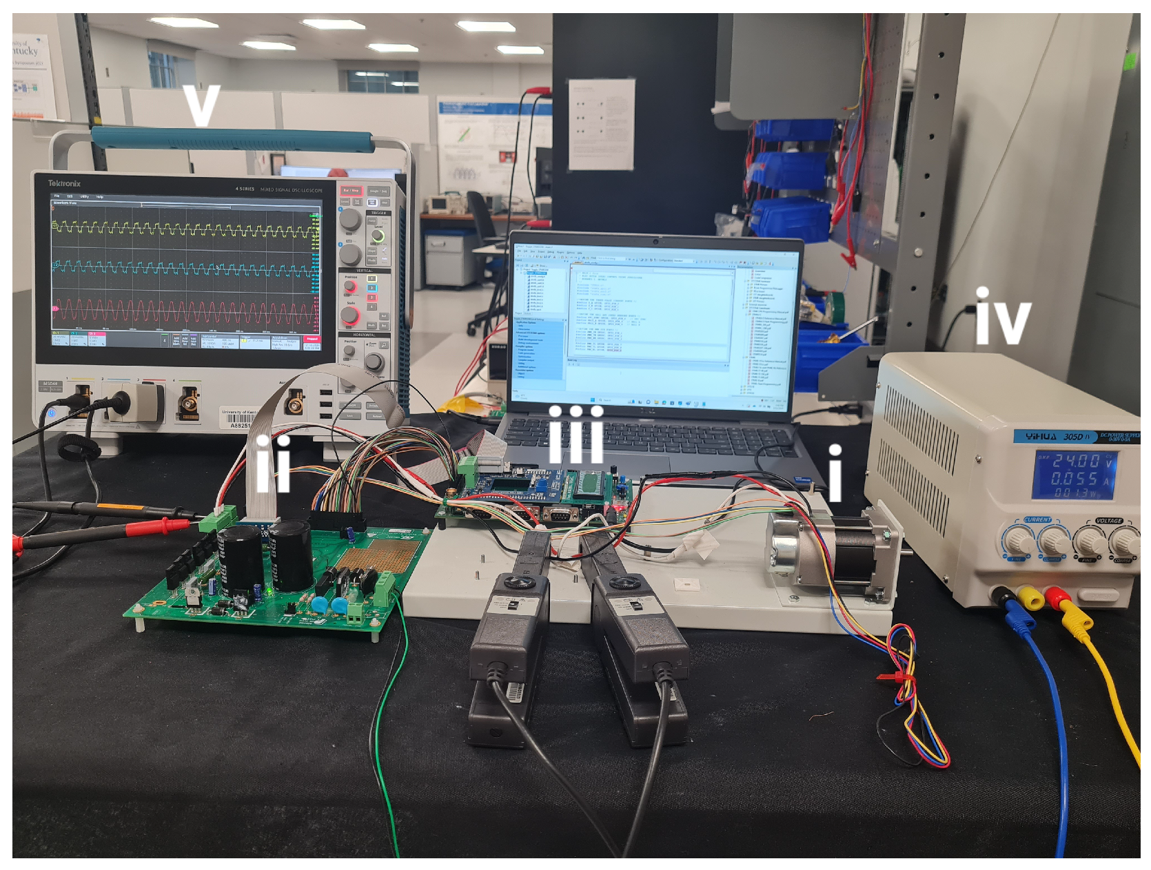
  • A lab-scale BLDC motor-drive prototype is implemented to verify the proposed inverter fault diagnosis approach.
Table 1. Comparison of Fault Detection Methods.
Ref.Motor
Type
Diagnosis
Technique
Fault
Identification
ComplexityRobustness
Analysis
[13]BLDCCurrent path🗸High×
[23]PMSMConvolutional
neural network
🗸Medium×
[24]-Ensemble bagged
tree machine learning
🗸Medium🗸
[25]PMSMFeature changes
of current waveforms
🗸Low🗸
Prop.BLDCSpectral analysis
of current waveforms
🗸Low🗸

2. Proposed Fault Diagnosis Methodology

This section sheds light on the proposed fault diagnosis method. First of all, the co-simulation system overview is introduced, highlighting the optimal motor design, inverter topology, and the control design. After that, the fault detection technique is investigated, with the fault signatures and flowchart of the proposed methodology presented.

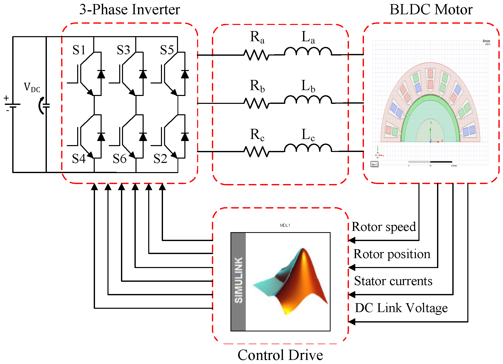
2.1. Co-Simulation System Overview

The co-simulation structure of the BLDC motor-drive system, developed in Ansys Twin Builder, comprises a 3-phase 18-slot/10-pole BLDC motor, a 2-level 3-phase inverter, the motor phase resistance and leakage inductance, and a BLDC current controller, as shown in Figure 2. The BLDC motor is equipped with fractional-slot winding based on the stator shifting concept, which mitigates the inevitable slot harmonic. Figure 3 depicts the 18-slot/10-pole fractional-slot winding arrangement. The initial BLDC motor is designed based on the well-known sizing equation and then optimized using the multi-objective genetic algorithm (MOGA). To avoid repetition, the design optimization process can be reviewed in [26]. Several objectives are considered in the optimization cost function, such as the average output torque, peak-to-peak torque ripple, and core losses. The optimization process is performed using Ansys Electronics Desktop, and the optimization results are given in Figure 4. At the optimal operating point, the best trade-off between the three objectives was realized. It is evident that the optimum design is emphasized and the objective function is minimized. Table 2 lists the motor design ideal parameters.
Furthermore, the 2-level voltage source inverter is modeled in Ansys Twin Builder. Finally, the BLDC current controller is implemented using Simulink. In essence, a square-wave drive that excites two phases at a time feeds the BLDC motor and produces a trapezoidal back EMF. The variations in the stator phase current are used as fault signatures in the proposed fault diagnosis technique. Depending on where the faulty switch is located, the current waveform varies when an inverter switch open-circuit fault happens. Under such circumstances, current waveform patterns offer a straightforward approach to locating the open-circuit fault.

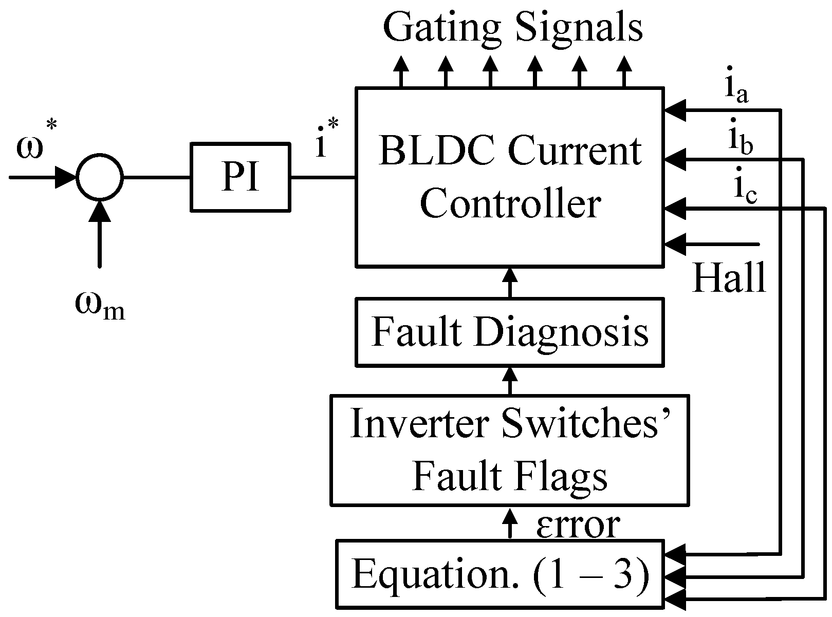
2.2. Fault Diagnosis Technique

This paper proposes a robust fault detection and identification method for the inverter open-circuit switching faults using the stator current signature analysis [27]. In this case, the spectrum of the stator phase currents is analyzed under healthy and faulty conditions based on discrete Fourier transform (DFT) spectral analysis to diagnose the open-circuit faults in the BLDC motor drives. The motor speed determines each time interval at which the energy spectral density (ESD) for each phase is calculated. To calculate the ESD error of each phase, the ESD values at each time interval are compared with those from the preceding time interval. Consequently, if the stator phase currents’ ESD errors are more than the 5% ESD value in the healthy scenario, a fault is identified. The purpose of calculating the ESD error proportion is to prevent the diagnosis of any transient disturbance. The DFT and ESD values are calculated as follows:
I ( f ) = n = 0 N 1 i n e 2 π i k n / N , 0 k N 1
S m ( f ) = I ( f ) 2
e r r o r = S m ( f ) S m 1 ( f )
where I ( f ) is the Fourier transform of the stator currents, S m ( f ) and S m 1 ( f ) are the ESD values at the current and previous intervals, respectively, and error constitutes the ESD error. The proposed fault detection method analyzes the BLDC motor electromagnetic performances under the inverter switching faults. The BLDC motor is operated at 1500 rpm rated speed and 1 Nm load torque. When the switch S 1 fails, the current waveforms of all phases are affected, especially, the current waveform of Phase A which flows only in the negative half cycle. The same conclusion can be drawn when the switch S 4 fails, while the Phase-A current is only produced in the positive half cycle. Table 3 reveals the calculated ESD values in both healthy and open-circuit faulty cases of the switches S 1 and S 4 . The maximum ESD errors correspond to Phase A, i.e., the faulty phase, in both cases. The ESD errors of Phase A can be generalized for the remaining phases due to the symmetry of the BLDC motor. For instance, simulation results are conducted under the open-circuit faults of the switches S 3 and S 5 . These results show that the maximum ESD errors are related to phases B and C, respectively. Based on the ESD values listed in Table 3, the ESD error percent of the ESD value can be calculated. The ESD error percents are 62%, 12%, and 15% for phase A, B, and C, respectively, when the open-circuit S 1 fault happens. Similarly, 41%, 15%, and 7% are the ESD error percents for phase A, B, and C, respectively, when the open-circuit S 4 fault occurs. Moreover, the the maximum ESD percentage varies between 1 and 4% in the healthy case. Thus, a 5% threshold is selected in this paper.
In addition to the fault diagnosis capability, the proposed methodology is capable of locating the faulty switch’s position based on the fault flags that are determined with respect to the signs of the measured ESD errors. A faulty phase flag (FPF) and faulty switch flag (FSF) are utilized to detect and localize the inverter open-circuit faults. The FPF is adjusted based on the maximum ESD error, e.g., FPF is ‘1’, ‘2’, or ‘3’ when phases A, B, or C are faulty, respectively. Moreover, the FSF is set based on the sign of the ESD error, i.e., FSF is ‘1’ or ‘ 1 ’ when the ESD error is positive or negative, respectively. Fault flags are listed in Table 4 for the open-circuit faults of the six switches S 1 6 . It is worth mentioning that the the ESD errors of the switches S 1 and S 4 in Table 3 are used to complete the fault flags in Table 4.
To further illustrate the proposed fault diagnostic method, a flowchart depicting the fault detection and identification technique is shown in Figure 5, which comprises various steps stated as follows:
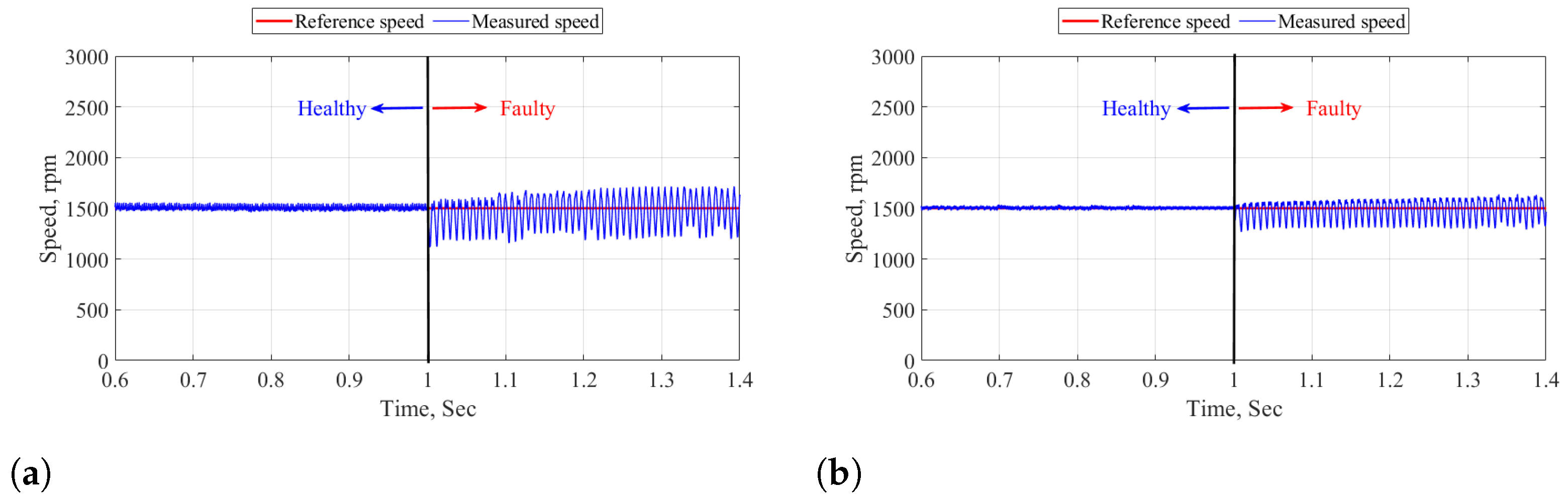
  • The reference speed is compared with the measured speed and the error is minimized using a proportional integral (PI) controller. The reference current, i * , is therefore determined and is sent to the BLDC current controller.
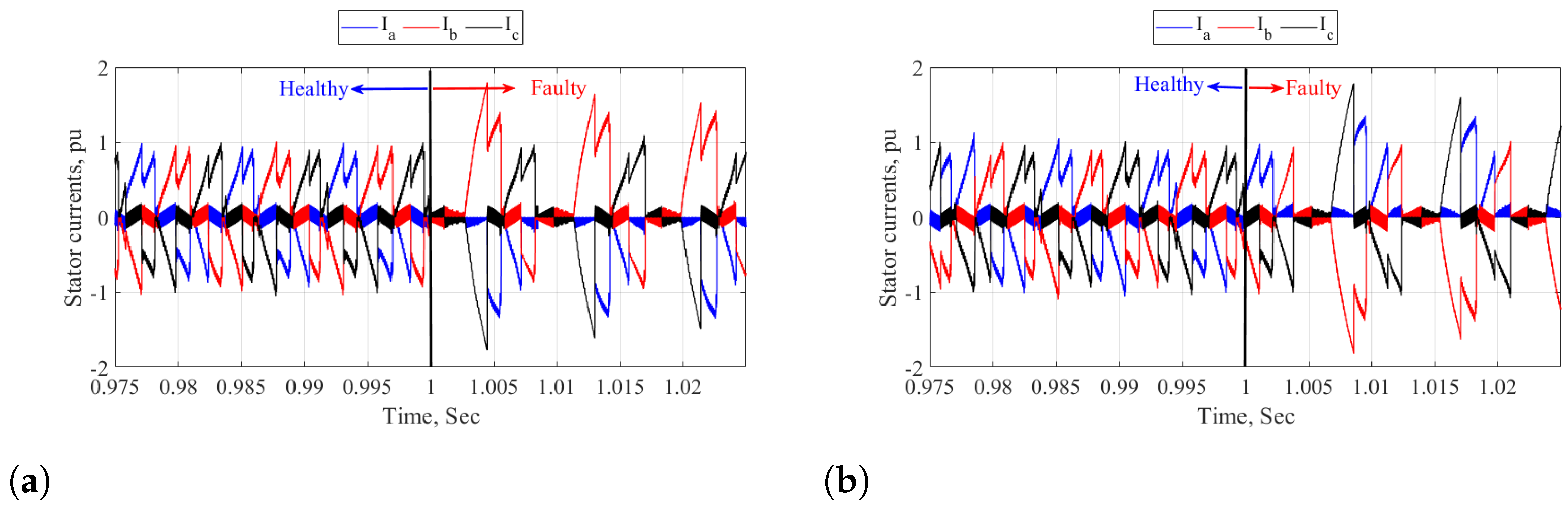
  • The stator currents are continuously monitored during BLDC motor operation, and Hall effect sensors are used to identify the rotor position. These measurements are received by the BLDC current controller.
  • The DFT and ESD values of the measured stator currents are calculated by Equations (1)–(3). With the knowledge-based table, i.e., Table 4, and the ESD error between the current and previous time intervals, the fault diagnoses are obtained under various fault scenarios.
  • The six switches of the inverter receive high-frequency gating signals. It is important to note that one electrical cycle is the minimal time interval required for precise fault identification.
Figure 5. Flowchart of the proposed fault diagnosis method.
Machines 12 00430 g005

3. Co-Simulation Results

This section presents the co-simulation results of the BLDC motor drive using the Ansys Twin Builder under healthy and open-circuit fault scenarios. Simulations were carried out in the cases of open-circuit faults of the six inverter switches. As an illustrative example, one case is presented when the open-circuit fault of the upper switch S1 is applied at t = 1 s. It is clear that the rotor measured speed follows the reference speed in both healthy and faulty cases, as shown in Figure 6a. However, speed oscillations considerably increase during the S1 open-circuit fault. Moreover, the three-phase stator currents and their associated frequency spectrum are shown in Figure 7a and Figure 8a, respectively. Under BLDC motor healthy operation, the stator currents are balanced, as shown in Figure 7a. However, the current of phase A becomes significantly distorted, i.e., the current flows only during the negative half cycle, and the currents of phases B and C are changed, i.e., the currents do not flow through motor windings based on the rotor position, during the S1 open-circuit fault. Furthermore, the frequency spectrum of the stator currents is depicted in Figure 8a, showing that the three phases have the same frequency spectrum with only odd harmonics under the healthy case. Under the faulty case, the frequency spectrum is completely changed according to the changes in the phase current’s patterns, and both odd and even harmonics exist. In that case, phase A has the maximum ESD error.
Another case is introduced when the open-circuit fault of the lower switch S4 is presented at t = 1 s. These two cases are investigated to show the BLDC motor performance when Phase A fails, and similar results can be obtained when the remaining two phases fail due to the symmetry of BLDC motors. Figure 6b presents both the reference and measured speeds under healthy and faulty cases, highlighting that the measured speed tracks the reference one with significant oscillations when the S4 fault is applied. Unlike the first case under the S1 open-circuit fault, the current of phase A only flows during the positive half cycle when the open-circuit fault of S4 is introduced, as shown in Figure 7b. Similarly, the three-phase currents are balanced under healthy conditions, and phase B and phase C currents are affected under faulty conditions. The frequency spectrum of the three-phase stator currents is depicted in Figure 8b in both healthy and faulty cases. Under healthy conditions, the frequency spectrum is the same for the three phases with only odd harmonics. On the contrary, even harmonics exist under faulty conditions due to the changes in the current waveform. Again, the maximum ESD error corresponds to phase A.
The torque profiles and thermal behaviors are presented based on 3D FE analysis using Ansys Workbench. Figure 9 depicts the torque profiles in both healthy and faulty cases. The average torque is reduced from 1 Nm to 0.67 Nm when the fault occurs in the inverter switches, whereas the peak-to-peak torque ripple is considerably increased from 0.403 Nm to 1.5 Nm in the healthy and fault cases, respectively. The higher the torque ripple, the higher the vibrations and noise in PM-based BLDC motors. The loss and temperature distributions are shown in Figure 10 and Figure 11, respectively. It is clear that the higher the losses, the higher the temperature under both operational modes. Furthermore, the losses are increased in the faulty case when compared to the healthy one and thus the temperature, e.g., the highest winding temperature, is increased from 67.8 °C to 84.5 °C when the fault occurs. This considerable increase in temperature may result in insulation degradation if the inverter fault is left undetected.
To further verify the necessity of online health monitoring of the robotic arm joint motor drives, simulations were carried out on the Kinova Gen3 robotic arm using the Pybullet 3.2.6 software in both healthy and faulty cases. Two trajectories are presented, namely, the healthy case without faulty joints and the faulty case with two locked-joint failures, as shown in Figure 12 and Figure 13, respectively. Figure 12 shows the trajectory where no joint failure occurs. The green point represents the desired position of the robot’s end-effector, and the green, blue, and red axes associated with this point represent the desired orientation of the end-effector. As can be seen in this figure, this workspace location clearly lies within the robot’s reachable workspace as Figure 12d demonstrates that the robot can successfully reach it.
On the contrary, Figure 13 shows the trajectory after joints 2 and 4 experienced locked-joint failures, given the same starting configuration and desired workspace location. As clear in Figure 13d, this workspace location is no longer in the robot’s reachable workspace after the locked joint failures. This demonstrates the need for fault-tolerant motion planning algorithms that can guarantee task completion after arbitrary joint failures, which is made possible by online health monitoring and fault detection.
Eventually, the robustness of the proposed fault diagnosis technique is tested under different speed and load conditions, as listed in Table 5. Numerous cases have been introduced at the rated speed while changing the load. For each case, not only the ability to diagnose the fault is examined but also the capability to identify the faulty switch is also verified. For each case, the fault is generated at one of the six inverter switches, and the ESD errors are calculated, as explained in the previous section. The validity of the proposed diagnosis technique is classified based on the fault diagnosis and identification capabilities, e.g., cases 1 and 4 are valid for fault detection and localization. However, some cases are only valid for fault diagnosis and are not capable of fault identification, such as cases 3 and 5. The main drawback of the proposed diagnosis technique is that it fails at low speeds, as demonstrated in case 6. Intensive work will be carried out to improve the robustness of the proposed technique under low-speed conditions.

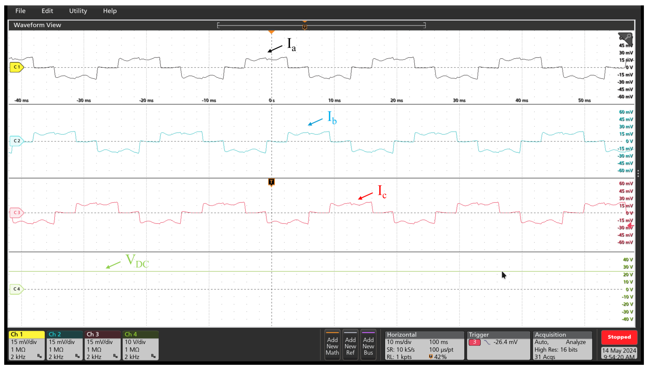
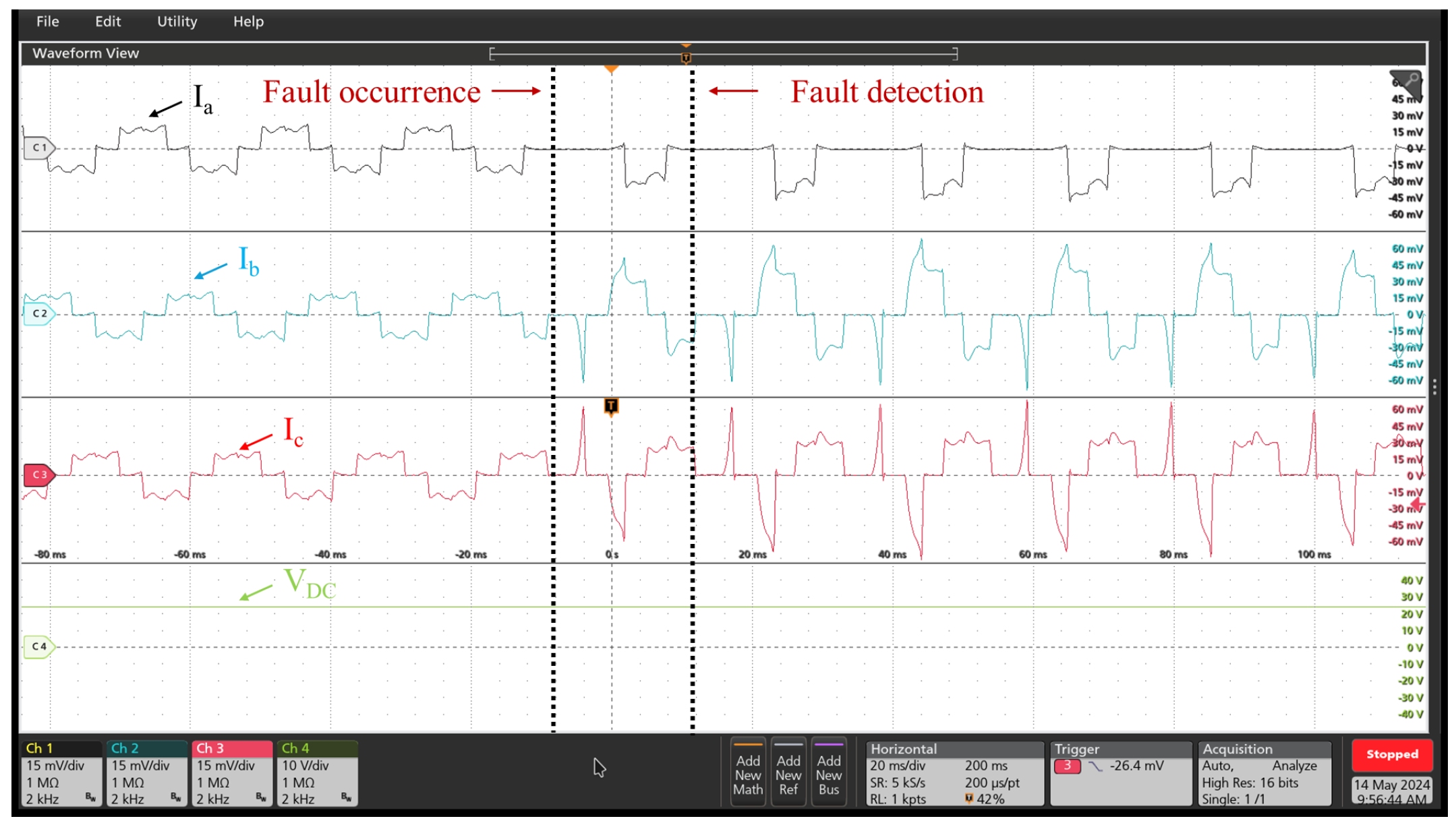
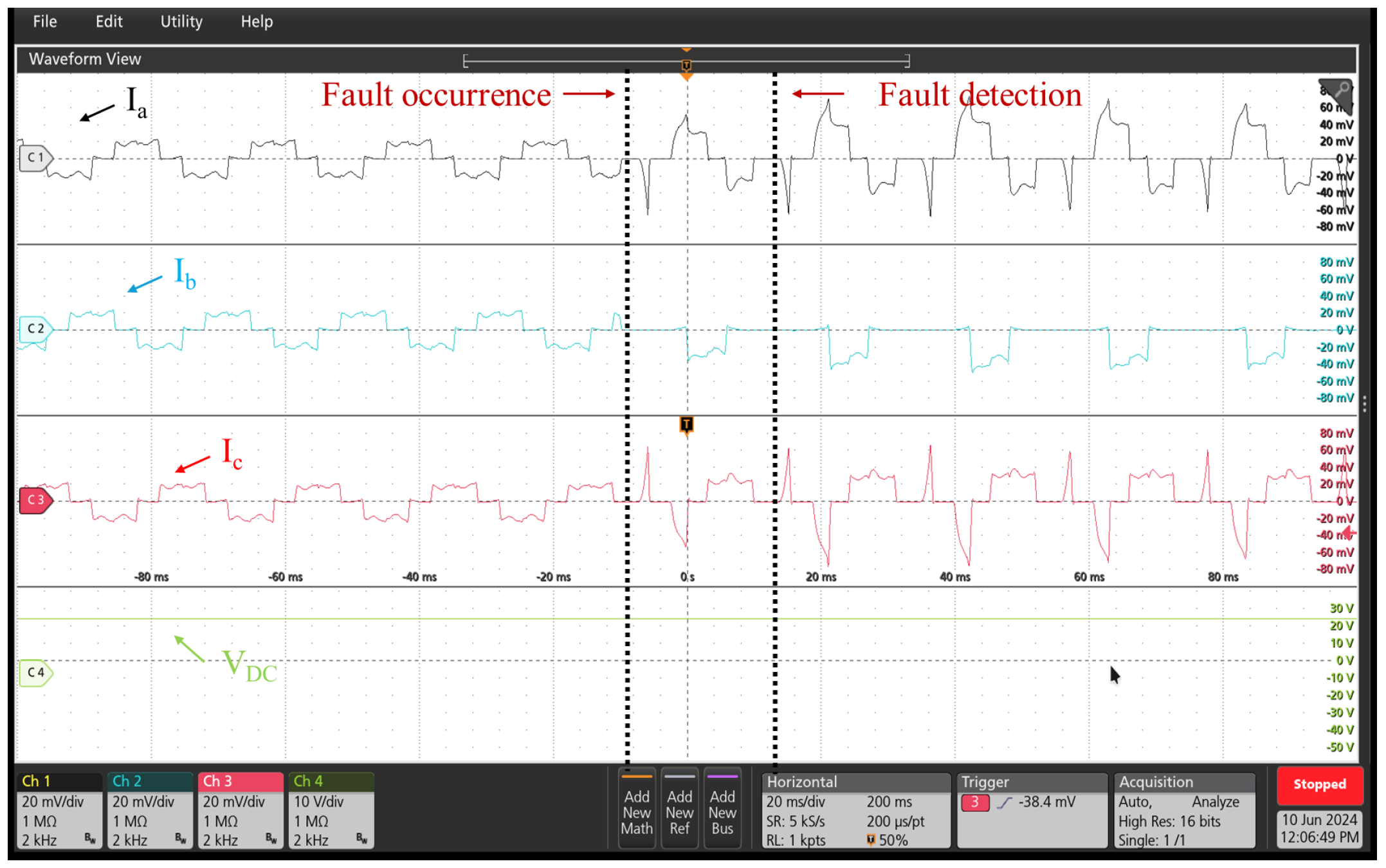
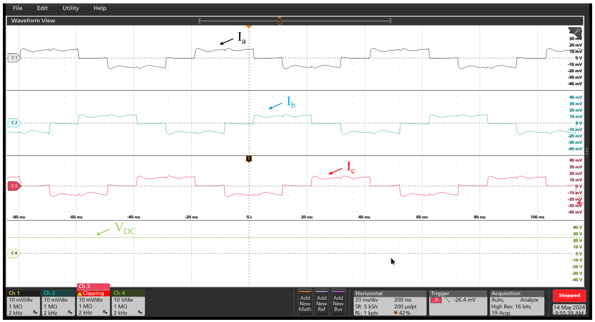
4. Experimental Verification

To verify the efficacy of the proposed fault diagnosis technique, experiments were carried out on the motor-drive test bench shown in Figure 14. Experiments were conducted at the rated speed of 1500 rpm and DC link voltage of 24 V for robotic applications. The PWM-based BLDC speed control is implemented in the propulsion mode [28]. The BLDC motor is tested under both healthy and faulty scenarios. The open-circuit fault of the upper switch S 1 represents the faulty case by the enforced off signal of the gate driver because the effect of the open-circuit fault in any other switch is assumed to be symmetrical. Figure 15 depicts the stator currents and the DC-link voltage in the healthy case. It is clear that the balanced square-wave currents and a trapezoidal voltage waveform can be achieved at the motor terminals under healthy operating conditions.
When the S 1 open-circuit fault occurs, at the rated speed, the corresponding stator currents are shown in Figure 16. Before the fault occurrence, the three-phase currents are balanced. After the fault occurrence, the currents are significantly distorted, i.e., the currents of phase B and C do not flow through motor windings based on the rotor position and the current of phase A only flows during the negative half cycle. A fault is detected after one fundamental cycle which is determined by the fundamental frequency. It is worth noting that the co-simulation and experimental results show good agreement with the same stator current waveforms. Moreover, the motor noise is increased when the switch S 1 is open-circuited. This is proved by the increase in the torque ripple in the faulty case, which is highlighted in the previous Section. To further investigate the fault detection methodology, the motor performance is studied in other faulty cases, e.g., S 3 and S 5 open-circuit faults. At the rated speed, the stator currents under S 3 and S 5 open-circuit faults are shown in Figure 17 and Figure 18, respectively. The current of phases B and C only flow during the negative half cycle, respectively, and the currents of the remaining two phases are distorted. This proves the symmetry of the BLDC motor. In this paper, it is assumed that a single fault occurs at a time. Surely, multiple faults can happen at a time, but it is rare. For fault-tolerant reconfiguration, the four-switch three-phase (4S3P) topology can be utilized with a derating factor, or a redundant leg can be used for a single-switch fault. On the other hand, for multiple switches, an extra inverter may be required for fault tolerance.
Furthermore, the BLDC motor performance at the low speed of 500 rpm is investigated under healthy and faulty conditions, as shown in Figure 19 and Figure 20, respectively. In the healthy case, the motor exhibits balanced three-phase currents; however, the currents are distorted in the faulty case. The proposed fault detection technique fails to accurately detect faults at the low-frequency due to the reduced switching frequency. This issue can be tackled using advanced signal processing techniques such as wavelet analysis, which will be considered for future work to enhance the robustness of the proposed fault diagnosis technique.
Finally, the dynamic response of the BLDC motor is given in the healthy case. Figure 21 and Figure 22 show the step speed and step load response under the healthy scenario, respectively. It is clear that the controller can effectively respond to the speed change from 1500 to 500 rpm. The experimental results prove that the proposed method can detect the fault occurrence in a fast and robust manner and an error message, fault occurred over current, is displayed on the control board.

5. Conclusions

This paper presents an online inverter open-circuit fault detection method for robotic arm joint BLDC motor-drive systems using the stator phase current information. Both finite element co-simulation results and experiments were conducted to validate the proposed fault diagnosis strategy when an inverter switch open-circuit fault happens. A satisfactory agreement between both experimental and finite element results with respect to the stator currents in healthy and faulty cases was highlighted. Moreover, the impacts of the faulty switch on the motor performances, e.g., peak-to-peak torque ripple and winding temperature, have been highlighted using 3D finite element analysis. The winding temperature is considerably increased when the open-circuit fault occurs, at which the rise in temperature may deteriorate the winding insulation. Eventually, extensive simulations under different speed and load scenarios proved the robustness of the proposed fault detection and identification technique. This study shows that fault prognosis and diagnosis are crucial for motor drives utilized in robotic applications to enhance the reliability of the system and avoid economic loss. This is proved by highlighting the impacts of the inverter switching faults at a motor-drive system level. Since joint motor and inverter failures may yield locked-joint failures, i.e., the most common failures in robotic arms, simulations were conducted for the Kinova Gen-3 robot arm using PyBullet software to highlight the effect of locked-joint failure on the reachability of the robot arms.

Author Contributions

Methodology, M.Y.M. and V.M.L.; formal analysis, M.Y.M. and C.L.C.; resources, J.H. and B.X.; data curation, M.Y.M. and V.M.L.; writing—original draft preparation, M.Y.M.; experiments, M.Y.M. and V.M.L.; writing—review and editing, J.H. and B.X.; supervision, J.H. and B.X.; project administration, J.H. and B.X.; funding acquisition, J.H. and B.X. All authors have read and agreed to the published version of the manuscript.

Funding

This material is based upon work supported by the U.S. National Science Foundation under Grant No. 2205292.

Data Availability Statement

The original contributions presented in the study are included in the article, further inquiries can be directed to the corresponding author.

Conflicts of Interest

The authors declare no conflicts of interest.

References

  1. Wang, W.; Gao, W.; Zhao, S.; Cao, W.; Du, Z. Robot protection in the hazardous environments. In Robots Operating in Hazardous Environments; IntechOpen: London, UK, 2017; pp. 87–107. [Google Scholar]
  2. Mu, Z.; Han, L.; Xu, W.; Li, B.; Liang, B. Kinematic analysis and fault-tolerant trajectory planning of space manipulator under a single joint failure. Robot. Biomim. 2016, 3, 1–10. [Google Scholar] [CrossRef] [PubMed]
  3. Trevelyan, J.; Hamel, W.R.; Kang, S.-C. Robotics in hazardous applications. In Springer Handbook of Robotics; Springer: Berlin/Heidelberg, Germany, 2016; pp. 1521–1548. [Google Scholar]
  4. Phuengsuk, R.; Suthakorn, J. A study on risk assessment for improving reliability of rescue robots. In Proceedings of the 2016 IEEE International Conference on Robotics and Biomimetics (ROBIO), Qingdao, China, 3–7 December 2016; IEEE: Piscataway, NJ, USA, 2016; pp. 667–672. [Google Scholar]
  5. Jung, M.Y.; Taylor, R.H.; Kazanzides, P. Safety design view: A conceptual framework for systematic understanding of safety features of medical robot systems. In Proceedings of the IEEE International Conference on Robotics and Automation (ICRA), Hong Kong, China, 31 May–7 June 2014; pp. 1883–1888. [Google Scholar]
  6. Mushage, B.O.; Chedjou, J.C.; Kyamakya, K. Fuzzy neural network and observer-based fault-tolerant adaptive nonlinear control of uncertain 5-dof upper-limb exoskeleton robot for passive rehabilitation. Nonlinear Dyn. 2017, 87, 2021–2037. [Google Scholar] [CrossRef]
  7. Vasic, M.; Billard, A. Safety issues in human-robot interactions. In Proceedings of the 2013 IEEE International Conference on Robotics and Automation, Karlsruhe, Germany, 6–10 May 2013; pp. 197–204. [Google Scholar] [CrossRef]
  8. Dalla, V.K.; Pathak, P.M. Power-optimized motion planning of reconfigured redundant space robot. Proc. Inst. Mech. Eng. Part I J. Syst. Control. Eng. 2019, 233, 1030–1044. [Google Scholar] [CrossRef]
  9. Chen, G.; Li, L.; Fu, Y.; Yuan, B.; Fei, J. Halt optimization strategy for a space manipulator with a joint-locked failure. Int. J. Aerosp. Eng. 2020, 2020. [Google Scholar] [CrossRef]
  10. Hwang, C.; Li, P.L.; Liu, C.-T.; Chen, C. Design and analysis of a brushless DC motor for applications in robotics. IET Electr. Power Appl. 2012, 6, 385–389. [Google Scholar] [CrossRef]
  11. Morel, C.; Gueux, B.L.; Rivero, S.; Chahba, S. Currents Analysis of a Brushless Motor with Inverter Faults—Part II: Diagnostic Method for Open-Circuit Fault Isolation. Actuators 2023, 12, 230. [Google Scholar] [CrossRef]
  12. Gautam, S.P.; Jalhotra, M.; Sahu, L.K.; Kumar, M.R.; Gupta, K.K. A Survey on Fault Tolerant and Diagnostic Techniques of Multilevel Inverter. IEEE Access 2023, 11, 60866–60888. [Google Scholar] [CrossRef]
  13. Li, X.; Li, S.; Chen, W.; Shi, T.; Xia, C. A Fast Diagnosis Strategy for Inverter Open-Circuit Faults Based on the Current Path of Brushless DC Motors. IEEE Trans. Power Electron. 2023, 38, 9311–9316. [Google Scholar] [CrossRef]
  14. Halabi, L.M.; Alsofyani, I.M.; Lee, K.-B. Multi Open-/Short-Circuit Fault-Tolerance Using Modified SVM Technique for Three-Level HANPC Converters. IEEE Trans. Power Electron. 2021, 36, 13621–13633. [Google Scholar] [CrossRef]
  15. Huang, W.; Luo, L.; Du, J.; Xiang, B.; Mei, S.; Zhou, L.; Fan, Q. Open-Circuit Fault Detection in PMSM Drives Using Model Predictive Control and Cost Function Error. IEEE Trans. Transp. Electrif. 2022, 8, 2667–2675. [Google Scholar] [CrossRef]
  16. Yan, H.; Xu, Y.; Cai, F.; Zhang, H.; Zhao, W.; Gerada, C. PWM-VSI Fault Diagnosis for a PMSM Drive Based on the Fuzzy Logic Approach. IEEE Trans. Power Electron. 2019, 34, 759–768. [Google Scholar] [CrossRef]
  17. Onambele, C.; Mpanda, A.; Elsied, M.; Giacchetti, F. Co-simulation modeling of high performance motor-drive systems for aerospace applications. In Proceedings of the 2017 IEEE International Electric Machines and Drives Conference (IEMDC), Miami, FL, USA, 21–24 May 2017; pp. 1–6. [Google Scholar] [CrossRef]
  18. Mersha, T.K.; Du, C. Co-Simulation and Modeling of PMSM Based on Ansys Software and Simulink for EVs. World Electr. Veh. J. 2022, 13, 4. [Google Scholar] [CrossRef]
  19. Sharma, V.K.; Usman, A.; Rajpurohit, B.S. Fault Diagnosis of BLDC Motor Drive using Vibration Spectrum Analysis: Part II. In Proceedings of the 2020 IEEE International Power and Renewable Energy Conference, Karunagappally, India, 30 October 2020–1 November 2020; pp. 1–6. [Google Scholar] [CrossRef]
  20. Chen, X.; Zhang, Z. Open-Circuit Fault Diagnosis of T-Type Three-Level Inverter Based on Knowledge Reduction. Sensors 2024, 24, 1028. [Google Scholar] [CrossRef] [PubMed]
  21. Shen, H.; Tang, X.; Luo, Y.; Xie, F.; Shi, Z. Online Open-Circuit Fault Diagnosis for Neutral Point Clamped Inverter Based on an Improved Convolutional Neural Network and Sample Amplification Method Under Varying Operating Conditions. IEEE Trans. Instrum. Meas. 2024, 73, 3512612. [Google Scholar] [CrossRef]
  22. Zhou, Y.; Zhao, J.; Wu, Z. A Review of Symmetry-Based Open-Circuit Fault Diagnostic Methods for Power Converters. Symmetry 2024, 16, 204. [Google Scholar] [CrossRef]
  23. Łuczak, D.; Brock, S.; Siembab, K. Fault Detection and Localisation of a Three-Phase Inverter with Permanent Magnet Synchronous Motor Load Using a Convolutional Neural Network. Actuators 2023, 12, 125. [Google Scholar] [CrossRef]
  24. Ibem, C.N.; Farrag, M.E.; Aboushady, A.A.; Dabour, S.M. Multiple Open Switch Fault Diagnosis of Three Phase Voltage Source Inverter Using Ensemble Bagged Tree Machine Learning Technique. IEEE Access 2023, 11, 85865–85877. [Google Scholar] [CrossRef]
  25. Luo, Y.; Zhang, L.; Chen, C.; Li, K.; Li, K. Real-Time Diagnosis of Open Circuit Faults in Three-Phase Voltage Source Inverters. IEEE Trans. Power Electron. 2024, 39, 7572–7585. [Google Scholar] [CrossRef]
  26. Metwly, M.Y.; Clark, L.; Xie, B.; He, J. Optimally Designed BLDC Motor Equipped with Different Winding Layouts for Robotic Arms. In Proceedings of the 2023 IEEE Energy Conversion Congress and Exposition (ECCE), Nashville, TN, USA, 29 October–2 November 2023; pp. 6093–6098. [Google Scholar] [CrossRef]
  27. Metwly, M.Y.; Clark, L.; Xie, B.; He, J. Robust Online Diagnosis of Inverter Open-circuit Switching Faults for Robotic Joints with BLDC Motors. In Proceedings of the 2024 IEEE Applied Power Electronics Conference and Exposition (APEC), Long Beach, CA, USA, 25–29 February 2024; pp. 2308–2313. [Google Scholar] [CrossRef]
  28. Suganthi, P.; Nagapavithra, S.; Umamaheswari, S. Modeling and simulation of closed loop speed control for BLDC motor. In Proceedings of the 2017 Conference on Emerging Devices and Smart Systems (ICEDSS), Mallasamudram, India, 3–4 March 2017; pp. 229–233. [Google Scholar] [CrossRef]
Figure 1. Kinova Gen-3 robotic arm with 7 joint BLDC motors.
Machines 12 00430 g001
Figure 2. Co-simulation of a BLDC motor-drive system in Ansys Twin Builder.
Machines 12 00430 g002
Figure 3. The 18-slot/10-pole BLDC motor winding layout based on the stator shifting concept.
Machines 12 00430 g003
Figure 4. BLDC motor optimization Pareto front using Ansys Electronics Desktop.
Machines 12 00430 g004
Figure 6. Speed profiles under the inverter open-circuit faults: (a) faulty switch S 1 , and (b) faulty switch S 4 .
Machines 12 00430 g006
Figure 7. Stator three-phase current profiles under the inverter open-circuit faults: (a) faulty switch S 1 , and (b) faulty switch S 4 .
Machines 12 00430 g007
Figure 8. Harmonic spectra of stator currents under the inverter open-circuit faults: (a) faulty switch S 1 , and (b) faulty switch S 4 .
Machines 12 00430 g008
Figure 9. Torque profile under both operational scenarios: (a) healthy case, and (b) faulty case.
Machines 12 00430 g009
Figure 10. Loss distribution under both operational scenarios: (a) healthy case, and (b) faulty case.
Machines 12 00430 g010
Figure 11. Temperature distribution under both operational scenarios: (a) healthy case, and (b) faulty case.
Machines 12 00430 g011
Figure 12. Simulation results of the Kinova Gen-3 robotic arm using PyBullet software in the healthy case.
Machines 12 00430 g012
Figure 13. Simulation results of the Kinova Gen-3 robotic arm using PyBullet software in the faulty case.
Machines 12 00430 g013
Figure 14. Test bench: (i) BLDC motor, (ii) inverter, (iii) control board, (iv) DC supply, and (v) oscilloscope.
Machines 12 00430 g014
Figure 15. BLDC motor stator currents and DC-link voltage under healthy case at 1500 rpm.
Machines 12 00430 g015
Figure 16. BLDC motor stator currents and DC-link voltage in the S 1 faulty case at 1500 rpm.
Machines 12 00430 g016
Figure 17. BLDC motor stator currents and DC-link voltage in the S 3 faulty case at 1500 rpm.
Machines 12 00430 g017
Figure 18. BLDC motor stator currents and DC-link voltage in the S 5 faulty case at 1500 rpm.
Machines 12 00430 g018
Figure 19. BLDC motor stator currents and DC-link voltage in the healthy case at 500 rpm.
Machines 12 00430 g019
Figure 20. BLDC motor stator currents and DC-link voltage in the faulty case at 500 rpm.
Machines 12 00430 g020
Figure 21. Step speed response of the prototype BLDC motor.
Machines 12 00430 g021
Figure 22. Step load response of the prototype BLDC motor.
Machines 12 00430 g022
Table 2. BLDC Motor Parameters.
Power (W)157
Rated speed (rpm)1500
Rated torque (Nm)1
DC link voltage (V)48
Electric loading (A/mm)12
Stator outer diameter (mm)68.8
Stack length (mm)62
Air gap length (mm)0.5
Phase resistance ( Ω )0.1646
Table 3. ESD Values for Open-circuit S 1 and S 4 Faults.
SwitchS1
PhaseABC
ESD before fault619161266283
ESD after fault229653745309
ESD error−3895−751−974
SwitchS4
PhaseABC
ESD before fault620362766285
ESD after fault362572566768
ESD error−2577980482
Table 4. Inverter Switches’ Fault Flags.
FSF Phase AFSF Phase BFSF Phase CFPF
S1−1−1−11
S4−1111
S3−1−1−12
S61−112
S5−1−1−13
S211−13
Table 5. Robustness Analysis of the Diagnostic Method.
CaseSpeed (rpm)Torque (pu)Validity
115000.25🗸
215000.5🗸
Only for phases
315000.75🗸
Only for phases
415001🗸
510001🗸
Only for phases
65001×
Disclaimer/Publisher’s Note: The statements, opinions and data contained in all publications are solely those of the individual author(s) and contributor(s) and not of MDPI and/or the editor(s). MDPI and/or the editor(s) disclaim responsibility for any injury to people or property resulting from any ideas, methods, instructions or products referred to in the content.

