Article

Research on Vibration Characteristics of Bearingless Motorized Spindles Based on Multibody Dynamics

School of Mechanical and Power Engineering, Chongqing University of Science and Technology, Chongqing 401331, China
*
Author to whom correspondence should be addressed.
Machines 2024, 12(7), 458; https://doi.org/10.3390/machines12070458
Submission received: 5 June 2024 / Revised: 28 June 2024 / Accepted: 1 July 2024 / Published: 5 July 2024
(This article belongs to the Section Machine Design and Theory)

Abstract

:
During the service process of a bearingless motorized spindle (BLMS), its parameters change with both time and external conditions, leading to a decrease in the accuracy of the motorized spindle. Therefore, it is difficult to accurately describe the dynamic performance of a motorized spindle during its actual operation using deterministic parameters. In this paper, the interactions between the thermal deformation and vibration of a motorized spindle are explored. A dynamic model of the motorized spindle based on multibody dynamics and time-varying parameters is established, and a solution method for the dynamic model with uncertain parameters is investigated. Firstly, the reasons for the vibration in the BLMS are analyzed, and the influences of thermal deformation on the thermal eccentricity and inhomogeneous air gap of the BLMS are studied. A vibration model of the BLMS is established and solved to acquire the radial vibration displacement. Secondly, a discrete multibody dynamics model of the BLMS is built, and the center trajectory of the motorized spindle is attained by solving the multibody dynamics model. A prototype experimental platform of the BLMS is designed, and vibration tests are carried out. The experimental results show that the vibration amplitude of the BLMS increases with the running time and the maximum displacement exhibits a large deviation from the simulation results using the determined parameters, while there is a small deviation from the simulation results using uncertain parameters; this indicates that the solution of the multibody dynamics model of the BLMS described by uncertain parameters is closer to the experimental data. These research findings can provide a reference for the optimized design of BLMSs.

1. Introduction

Motorized spindles are key functional components of high-precision and high-efficiency CNC machine tools [1,2,3,4], and they affect the accuracy, stability, and application range of the whole machining process. BLMSs are a new type of motorized spindle structure, combining a bearingless motor with the spindle of the machine tool. This bearingless motor [5,6] adopts a double winding stator that can support the spindle while driving it to rotate, and it achieves the suspension of the spindle together with the magnetic bearings [7,8]. A BLMS eliminates the need for transmission and speed-change devices in traditional machine tools and achieves “zero transmission”, which not only further improves the speed of the spindle of CNC machine tools, but it can also be more conducive to the automation and intelligent control of the spindle system.
The vibration of motorized spindles in high-speed machining reduces the machining accuracy, which affects the surface quality of the workpiece, as well as the service life of the spindle. Therefore, dynamic performance analysis of motorized spindles is of great significance for improving the machining quality of the machine tool. At present, many scholars have conducted a lot of research on the vibration characteristics of motorized spindles [9]. Qiao and Hu [10] proposed an active control scheme with a built-in force actuator to improve the performance of a high-speed machining system for the unbalanced vibration of a flexible motorized spindle rotor. Bai et al. [11] established a vibration dynamics model of a broach spindle-bearing dual-rotor system for the vibration of the spindle nose during the cutting process of a high-speed motorized spindle; they also analyzed the vibration of the spindle under the action of cutting force. Cheng et al. [12] established radial vibration, tilt vibration, and axial vibration models of high-speed grinding spindles and discussed and analyzed the causes of the vibrations. Moreover, Zhang et al. [13] addressed the issue of unbalanced excitation that caused a spatial vibration in a high-speed motorized spindle; they developed a multi-degree-of-freedom finite element analysis model for a high-speed motorized spindle, determined the vibration patterns and the influence of spatial displacement on the excitation, and proposed a dynamic model-based strategy for suppressing unbalanced vibration. Chen et al. [14] put forward a technique for forecasting the rotary precision of a spindle by utilizing the vibration signal from the front axis of a motorized spindle using the local mean decomposition and long- and short-term memory. He et al. [15] suggested a hybrid state-feedback algorithm to make the vibration control of a high-speed motorized spindle-bearing rotor system more stable. This led to the creation of a Kalman-filtered observer for estimating the state perturbation, which made the system more stable. Bu et al. [16] conducted a study on an adaptive feedforward vibration compensation strategy, which effectively mitigated the in-phase displacement caused by unbalanced vibrations when the motor speed was subjected to sudden changes. There are numerous studies in the literature on the unbalanced vibration of motorized spindles; these studies have thoroughly explored the effect of external loading on the vibration of the primary shaft and have formulated various control techniques to minimize the vibration of the main axle. However, there has been no analysis of the influence of temperature field changes on motorized spindle vibrations that are caused by an increased energy consumption during operation.
At present, there have been many studies on the dynamic characteristics of motorized spindles. Shan and Chen [17] developed a comprehensive model for a motorized spindle, which included a model for the shaft dynamics, a thermo-mechanical model for the bearings, and a thermal model. They analyzed the motorized spindle’s dynamic performance under various bearing configurations. Furthermore, Liu and Yang [18] created a model of a tool, a shank, and a spindle, as well as their bonding surfaces and bearings. They examined how various parameters, such as the bearing stiffness and bonding surface stiffness, affected the motorized spindle’s dynamic characteristics. Kang et al. [19] put forward a method that predicts a spindle’s output torque and speed by analyzing the input voltage and current values of the stator of the motorized spindle; this method helps to determine the stability of its output torque and speed. Liu et al. [20] established a coupling model consisting of a thermo-mechanical dynamics model and a milling stability model, and they discussed and verified the influence of the thermo-mechanical coupling factors on the system’s transfer function of the cutting point and milling stability. Zhang et al. [21] proposed a new method for rigid motorized spindle balancing that can be integrated into a CNC system controller. This method is based on real-time position data from the CNC machine tool, which improves the efficiency of the dynamic balancing process. Xu et al. [22] developed a five-degrees-of-freedom model for angular contact ball bearings, as well as a comprehensive dynamics model consisting of a spindle, a tool holder, and a tool. They analyzed the variation in the bearing’s characteristic parameters with the preload and bearing speed, and they investigated the nonlinear dynamic response and stability of high-speed spindle systems at the bearing and tool tip. It can be seen that current research on the dynamic characteristics of motorized spindles focuses on the study of the dynamic performance of motorized spindles under specific conditions; however, there are few studies in the literature that have directly investigated the evolution of the dynamic characteristics of motorized spindles.
Above all, most of the current research on the dynamic performance of motorized spindles is based on deterministic parameters. However, when the motorized spindle is actually working, its parameters change, along with the time and external conditions. Therefore, deterministic parameters cannot really show how the dynamic performance of the motorized spindle changes. In this paper, the BLMS is taken as the research object, and the vibration characteristics for changes in parameters in the operation process are studied by adopting uncertainty parameters.

2. Materials and Methods

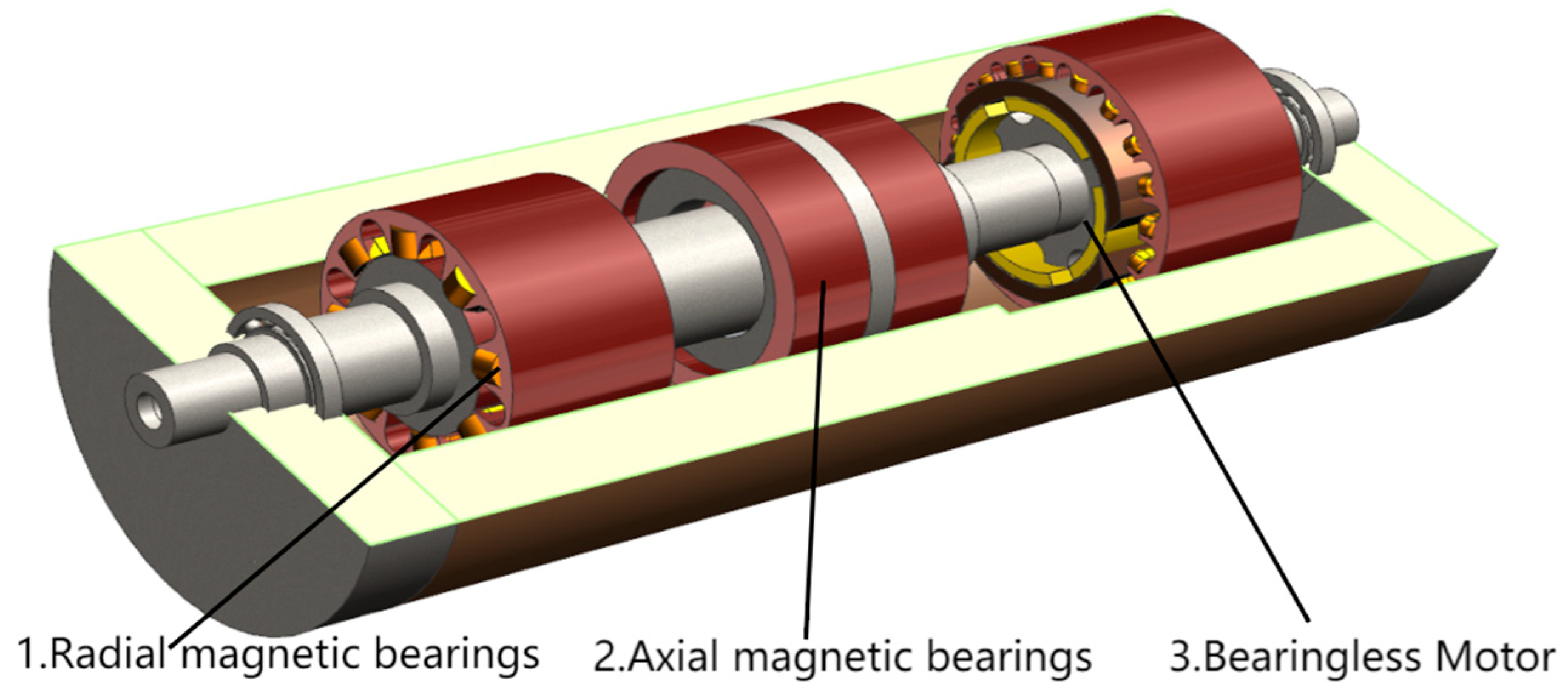
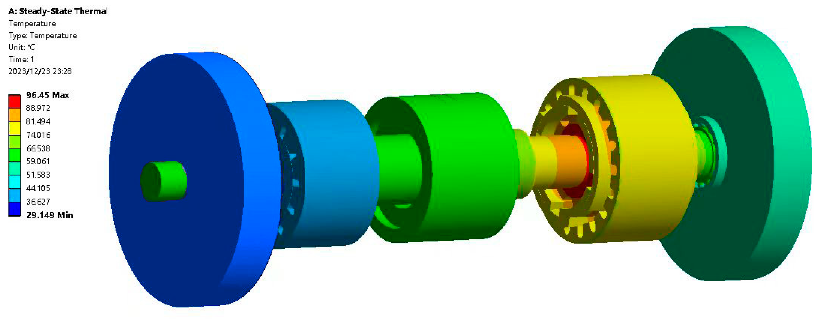
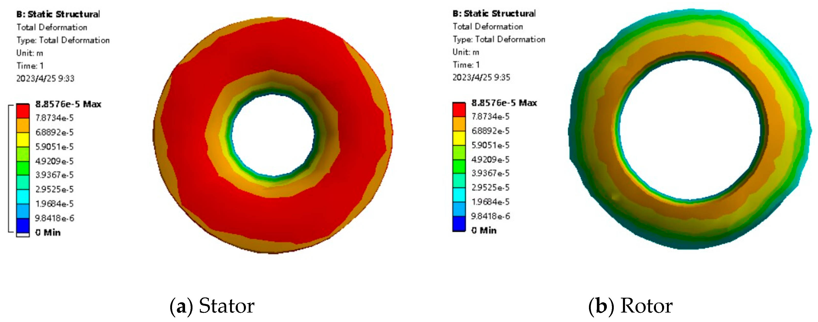
2.1. Finite Element Analysis of BLMS

The BLMS is mainly composed of radial magnetic bearings, axial magnetic bearings, a bearingless motor, and a spindle, as shown in Figure 1. The stator slot type of the bearingless motor is semi-closed, with 41 turns per slot, and a rated power of 1.1 kW. The winding type is single-layer cross, with a conductor wire diameter of 0.71 mm. Using a laboratory power supply with 220 V/50 Hz, the maximum speed is 36,000 r/min and the torque is 1.19 Nm.
In order to deeply understand the internal temperature distribution of the motorized spindle, thermal analysis is carried out using the finite element method. Table 1 and Table 2 show the conditions for the stator and rotor heat generation rates of the bearingless motor, the radial magnetic bearing heat generation rate, the axial thrust bearing heat generation rate, and the convective heat transfer coefficient in the air gap inside the spindle [23,24].
The steady-state temperature field of the BLMS is obtained using finite element analysis, as shown in Figure 2. It can be clearly seen that the internal temperature distribution of the spindle is not uniform and that the temperature difference is large; the highest temperature is located in the bearingless motor, with a temperature of about 96.45 °C. The reason for this is that the bearingless motor produces a significant amount of heat and is located inside the spindle, which makes it difficult to dissipate this heat effectively. The axial magnetic bearing is the second-highest temperature component, not only due to the high eddy current loss within the bearing, but also because it is close to the bearingless motor, which is the primary heat source in the spindle. Additionally, convective and direct heat transfer from the spindle further increase the temperature of the axial magnetic bearing. In contrast, the radial magnetic bearing has a lower heat generation rate and is located farther away from the heat source, resulting in a lower temperature. The heat generated by the radial magnetic bearing can be directly transferred to the outside world through the spindle [25,26,27,28].
The temperature field data were utilized as an input for static structural analysis, which yielded the thermal deformation of the BLMS for both the main rotor and stator. The results are illustrated in Figure 3.
The BLMS may experience uneven thermal expansion due to either uneven temperature distribution within the spindle or changes in thermal load. This eccentricity causes the rotor to be subjected to an additional unbalanced excitation force during operation [29,30], which, in turn, produces a certain vibration on the operation of the motorized spindle. Another aspect to be considered is that the air gap between the stator and the rotor is not uniform due to thermal deformation; as such, the inhomogeneous air gap leads to a non-uniform magnetic field distribution during the operation of the motorized spindle. Thus, the rotor is subjected to the action of unbalanced magnetic tension, causing rotor vibration [31,32].

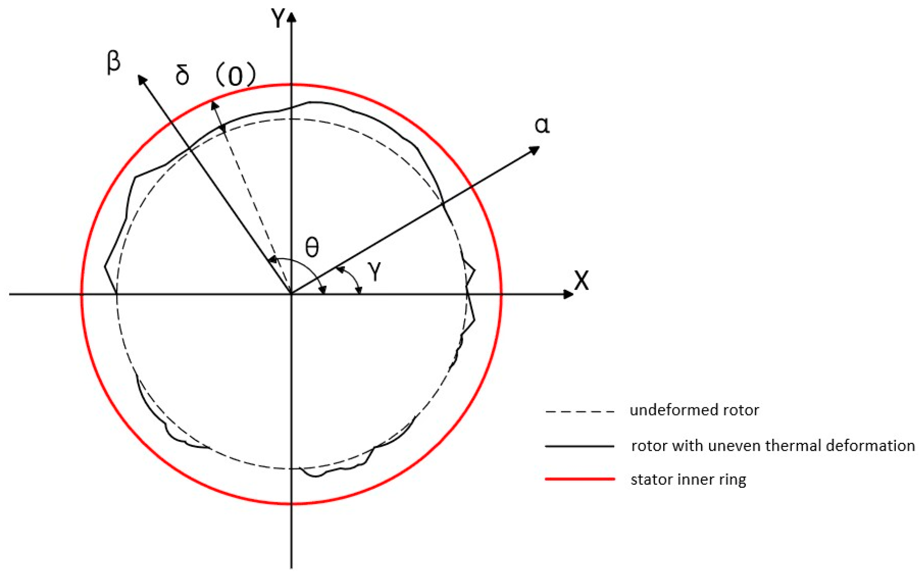
2.2. Mathematical Model of Thermal Eccentricity Unbalanced Excitation Force

The uneven mass distribution of a moving rotor results in the non-coincidence of the center of gravity with the geometrical center; this discrepancy gives rise to an additional centrifugal force, leading to an unbalanced phenomenon. This unbalanced force is usually caused by uneven temperature distribution, hence its designation as a thermal eccentric centrifugal excitation force. The coordinate system xoy is established with the geometric center of the spindle, the rotary center is located at point O , and the position of the center of mass offset due to thermal eccentricity is located at point m H . A schematic diagram of the rotor thermal eccentricity is shown in Figure 4.
In order to describe the effect of thermal eccentricity on rotor vibration, it is necessary to define the centrifugal excitation force on the rotor under thermal eccentricity conditions. Its formula can be expressed as follows:
  F m e x = m ω 2 e cos ω t + θ F m e y = m ω 2 e sin ω t + θ
where e —eccentricity distance; θ —initial phase angle; F m e x x direction thermal eccentric centrifugal excitation force; and F m e y y direction thermal eccentric centrifugal excitation force.

2.3. Mathematical Model of Unbalanced Magnetic Pull Due to Air Gap Inhomogeneity

Due to the effect of inhomogeneous thermal deformation between the stator and the rotor of the BLMS, the air gap is not uniformly distributed. In a BLMS, the air gap length is closely related to the distribution of the magnetic field; as the air gap length decreases, the magnetic field becomes more concentrated in the magnetic circuit, rather than dissipating into the air. This results in an increased magnetic induction intensity between the stator and the rotor, causing the magnetic force lines to become denser. Consequently, the magnetic pulling force on the rotor increases, leading to the generation of unbalanced magnetic forces. These unbalanced magnetic forces can induce vibrations and increase noise in the motorized spindle, thereby reducing its efficiency and lifespan.
Simplifying the thermal deformation of the rotor in Figure 3 to obtain Figure 5, the inhomogeneous air gap of the stator and rotor of the BLMS can be expressed as follows:
  δ θ , t = R r θ , t r 0
where δ θ , t —stator and rotor air gap after thermal deformation; r θ , t —angle θ radius of the rotor after thermal deformation; R —radius of inner circle of stator; and r 0 —radius of the rotor at the end of thermal deformation.
Expanding the air gap’s permeability between the stator and the rotor of a BLMS into the form of a series, the following applies:
Λ θ , t = μ 0 δ θ , t = μ 0 δ 0 n = 0 ε n cos θ γ = n = 0 Λ n cos θ γ
where δ 0 —the length of the air gap at the end of the eccentricity state; ε —relative eccentricity; ε = r θ , t r 0 δ 0 ; and μ 0 —air permeability coefficient. The Fourier coefficient Λ n is as follows:
Λ n = μ 0 δ 0 1 1 ε 2 n = 0 2 μ 0 δ 0 1 1 ε 2 1 1 ε 2 ε n n > 0
According to the operating principle of the BLMS, the base wave magnetic potential of the air gap of the motorized spindle without external load is expressed as follows:
  F θ , t = F j cos ω t p θ
where F j —basic wave magnetic potential of the excitation current; p —the number of magnetic pole pairs of the motorized spindle; and ω —current frequency. The air gap magnetization is distributed as follows:
  B = μ 0 F δ = Λ θ , t F θ , t
The magnetic field distribution in the air gap of the BLMS resembles that of a rotating magnetic pole. The magnetic field strength is primarily distributed along the air gap in the normal direction, with negligible tangential distribution. If we assume infinite magnetic permeability of the iron core, the Maxwell stress along the boundary between the rotor and air in the normal direction is expressed as follows:
σ = B 2 2 μ 0
The analytical expression for the unbalanced magnetic tension can be obtained by integrating Equation ( 7 ) into Equation ( 8 ), as follows:
F u m p x = 2 f 1 cos γ + f 2 cos 2 ω t γ + 2 f 3 cos 2 ω t 3 γ + f 4 cos 2 ω t 5 γ F u m p y = 2 f 1 sin γ + f 2 sin 2 ω t γ + 2 f 3 sin 2 ω t 3 γ + f 4 sin 2 ω t 5 γ
where f 1 = R L π 4 μ 0 F j 2 2 Λ 0 Λ 1 + Λ 1 Λ 2 + Λ 2 Λ 3 ; f 2 = R L π 4 μ 0 F j 2 ( Λ 0 Λ 1 + 1 2 Λ 1 Λ 2 + 1 2 Λ 2 Λ 3 ) ; f 3 = R L π 4 μ 0 F j 2 Λ 0 Λ 3 + 1 2 Λ 1 Λ 2 ; f 4 = R L π 8 μ 0 F j 2 Λ 2 Λ 3 ; F u m p x —x direction unbalanced magnetic tension; and F u m p y —y direction unbalanced magnetic tension.
The Jeffcott rotor model is used to calculate the effect of thermal deformation on spindle vibration. It consists of a massless elastic rotor shaft and a rotor disk with mass m. At the same time, the rotor disk is affected by linear damping and nonlinear stiffness, which are easy to model and analyze, allowing us to accurately predict the vibration response of the motorized spindle. Considering the thermal deformation of the BLMS, the Jeffcott rotor model coupling Equations (1) and (8) can be obtained:
  M d 2 x d t 2 + c d x d t + k x = F m e x + F u m p x M d 2 y d t 2 + c d y d t + k y = M g + F m e y + F u m p y

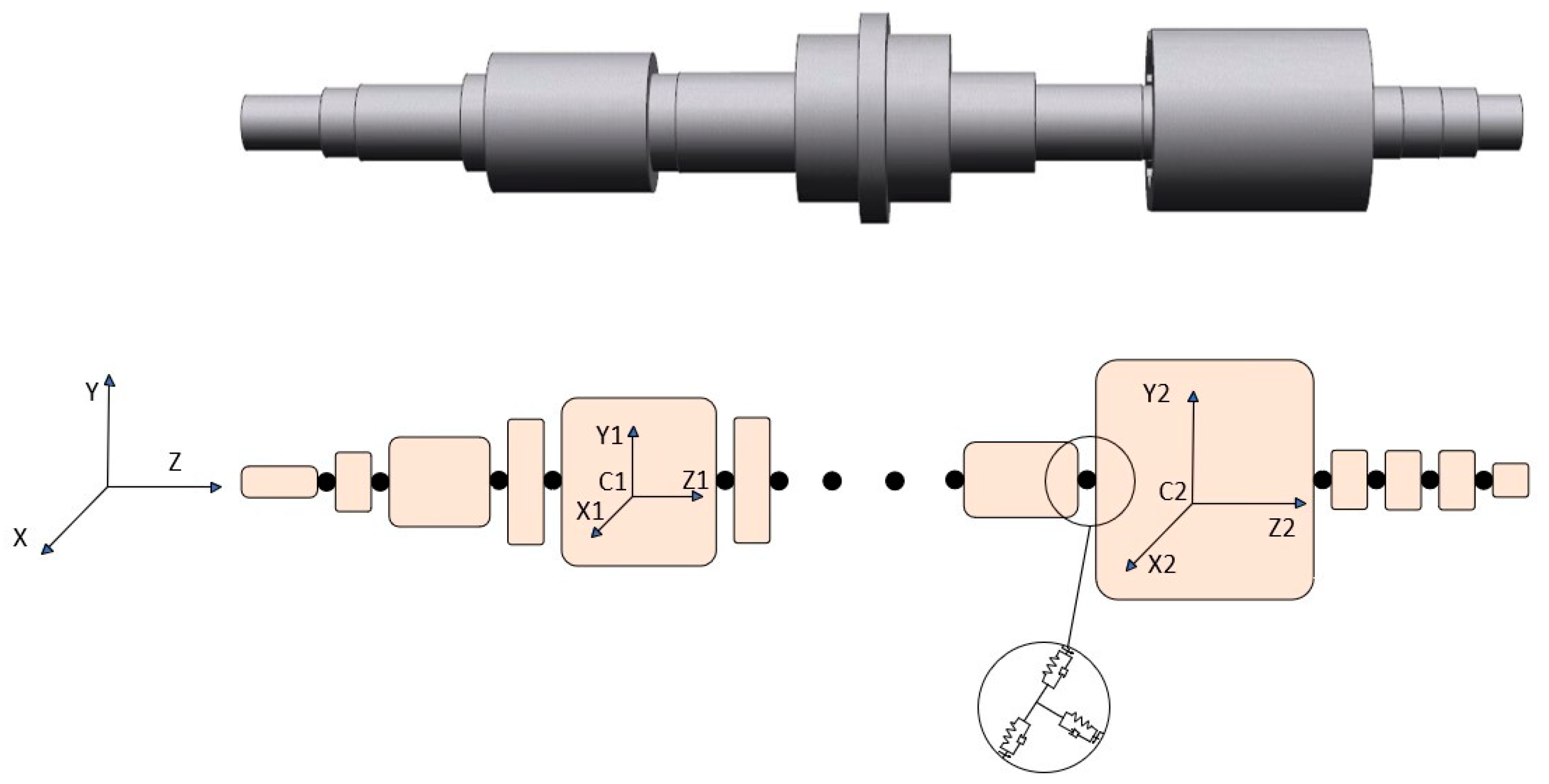
2.4. Discrete Multibody Dynamics Modeling of a BLMS

Based on the theory of multibody dynamics, the main shaft part of the BLMS is simplified and dispersed into N multi-rigid body systems that are formed by linking spherical joints, springs, and dampers according to its cross-sectional relationship, as shown in Figure 6. The spherical joint restrains the movement of the discrete spindle unit in three directions to simulate the torsion and bending deformation of the spindle; the spring and damper, respectively, replace the bending stiffness and structural damping of the spindle [33,34,35,36].
Inside a BLMS system, a spherical joint can be equivalent to simulating a connection point in the system that allows the rigid body to rotate freely in certain axes, and it can simulate rotational constraints between internal components. Springs can simulate the elastic properties of internal structures in a BLMS system. To discretize the motorized spindle into a system of rigid body, equivalent springs must be introduced at the rigid body hinge point. These springs generate an elastic force, which is equivalent to the bending and torsional stiffness of the motorized spindle operation, and simulate the elastic deformation between components. Additionally, the springs may also play a damping role in vibration. Dampers in BLMS systems are equivalent to simulating the energy dissipation and vibration damping characteristics of the internal structure. The damper can simulate the damping effect of the system, thus reducing unwanted vibrations and improving the stability and response characteristics of the system. Applying multibody dynamics theory, the continuous mass and infinite degrees of freedom in the shaft are discretized into a finite element model with n-order degrees of freedom. The overall BLMS system dynamics model of the system [37] was established as in Equation (10).
M Φ Λ T Φ q T Φ Λ 0 0 Φ q 0 0 q ¨ σ i Λ λ = b η Λ η + Q 0 0 + Q n 0 0 + Q k 0 0
where
M = M 1 0 0 M N ; b = 0 8 L T J 1 L Λ 1 0 8 L T J N L Λ N ; Q = F 1 2 L T M 1 F N 2 L T M N ; Q n = F 1 n 2 L T M 1 n F N n 2 L T M N n ; Q k = F 1 k 2 L T M 1 k F N k 2 L T M N k ;   ϕ Λ = ( 0   Λ 1 T ) 0 0 ( 0   Λ N T ) ; η Λ = Λ 1 T Λ 1 0 Λ N T Λ N
By incorporating spherical joints, springs, and dampers into the internal model of a BLMS system, the constraints, elastic properties, and damping effects of the system’s internal structure can be simulated and described; this allows us to better understand how these factors influence the overall dynamic behavior of the system. The modeling approach helps to analyze and optimize the performance of the motorized spindle system [38,39].
Thermal eccentricity and an inhomogeneous air gap are incorporated as uncertain parameters in the multibody dynamics model of the BLMS. Utilizing the Polynomial Chaos (PC) and Legendre Metamodel (LM) for characterizing the uncertain parameters within the multibody dynamics model, these parameters are incorporated into the discrete multibody dynamics model of the BLMS, as shown in Equation (11).
The discrete multibody kinetic equation for the spindle under the influence of thermal deformation is written as follows:
M C Φ Λ T Φ q T Φ Λ 0 0 Φ q 0 0 q ¨ σ i Λ λ = b η Λ η + Q ε 0 0 + Q n 0 0 + Q k 0 0
where
  M c = m R R 1 m R θ 1 m R θ 1 m θ θ 1 0 m R R N m R θ N 0 m R θ N m θ θ N
denotes the mass matrix of the spindle with mass imbalance.

3. Vibration Simulation of BLMS

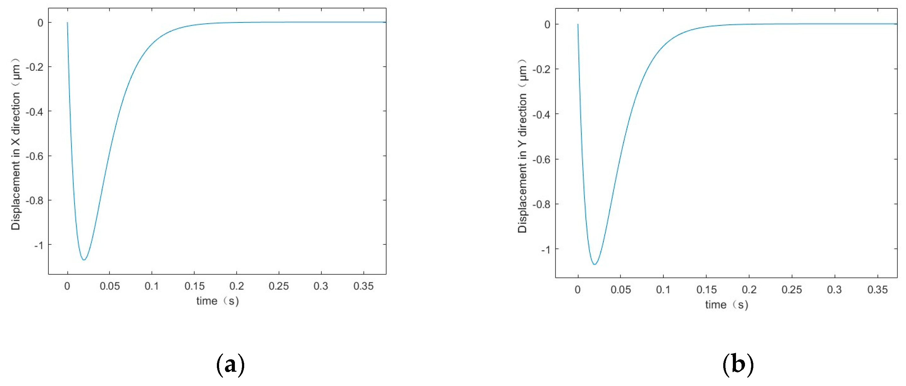
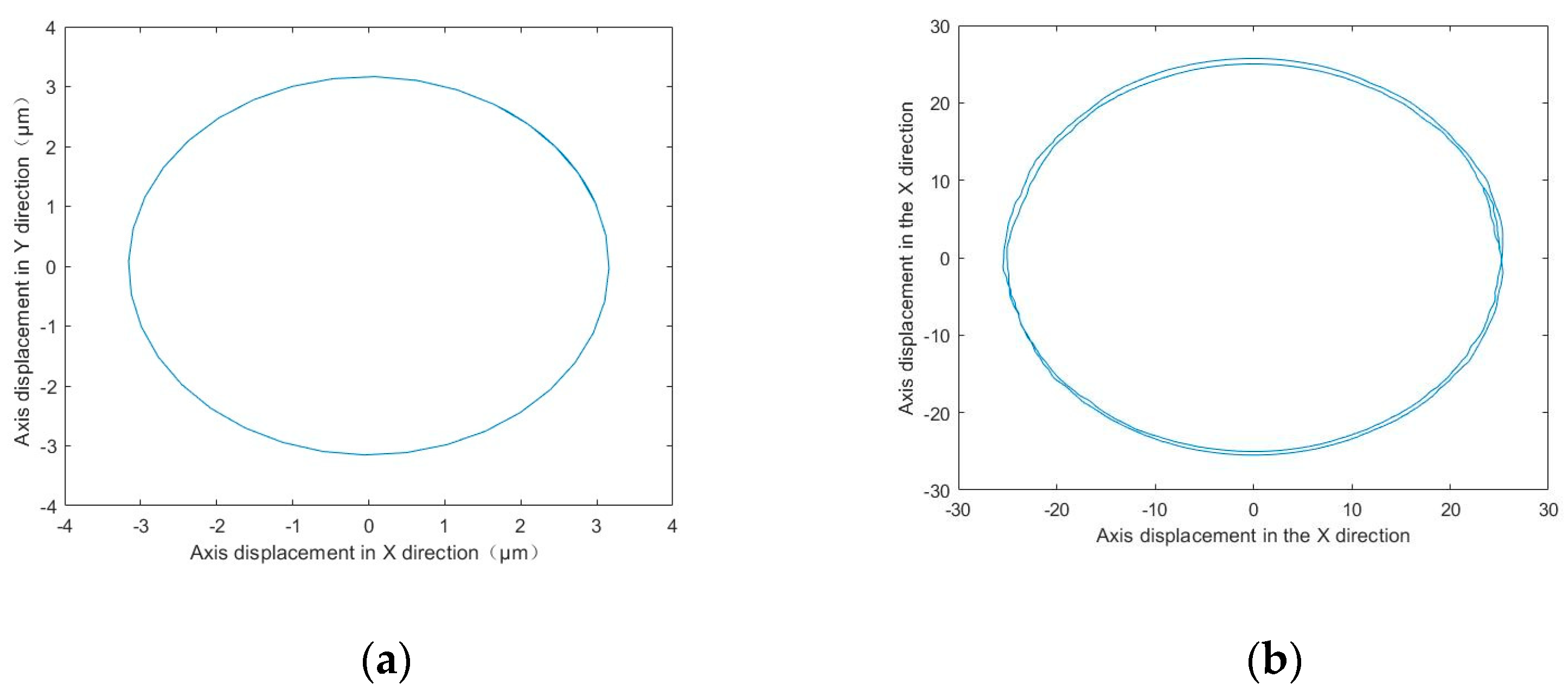
3.1. Thermal Deformation Vibration Simulation Based on Deterministic Parameters

Thermal eccentricity and the inhomogeneous air gap are significant factors that cause vibration in BLMSs. Therefore, the vibration characteristics are investigated in three different cases, as follows: (1) without considering the influence of external factors, (2) considering only the influence of the thermal eccentricity of the spindle, and (3) considering the influence of both thermal eccentricity and the inhomogeneous air gap simultaneously. The main parameters of the BLMS are as follows: m = 7.714 kg, rotor length L = 105 mm, rotor radius R = 48.5 mm, and vacuum permeability μ 0 = 4 π × 1 0 7   H / m . The determined parameters and the uncertain parameter cases of the motion are also compared.
Based on the above parameters, using the ode45 function in MATLAB to solve Equation ( 9 ), the displacement variation in the spindle in the x and y directions can be obtained. The thermal eccentric excitation force and unbalanced magnetic tension force in Equation ( 9 ) are not considered for solving the displacements of the spindle in the x and y directions, which are not affected by external factors; this is shown in Figure 7a,b.
As shown in Figure 7, when considering only the spindle displacement change without external factors, fluctuations occur at the beginning due to the torque pulsation that is generated during the motorized spindle’s start-up. This pulsation excites intrinsic vibration modes in the spindle system, resulting in a larger amplitude during the initial operation. As time passes, the spindle operation stabilizes and reaches a steady state, with vibration displacement presenting a linear state.
The nature of the discrete model of the multibody dynamics of the BLMS is a differential equation in matrix form. To solve this equation, the ode45 function in MATLAB 2020 is used to solve Equations ( 10 ) and ( 11 ). The ode45 function employs the 4th order 5-step Lunger Kuta algorithm, which allows us to obtain the motion of each discrete unit in the spindle’s discrete model. The results are presented in Figure 8.
In Figure 8, we can see the discrete unit axial trajectory displacement of the shaft’s protruding end under deterministic parameter calculations. Figure 8a displays the axial displacement of the spindle when it is not subjected to external loads, while Figure 8b shows the axial displacement under the consideration of thermal eccentricity of the rotor. From Figure 8a, we can observe that the spindle operates in a stable state when the influence of thermal deformation factors is not considered. However, when the BLMS is started, the spindle may experience a certain suspension displacement due to the joint action of the windings. This is caused by the electromagnetic force that moves the spindle from its initial stationary position and suspends it. When the motorized spindle starts to operate, the axial trajectory of the spindle will be circular, and the amplitude of its axial displacement will be around 3 μm.
As can be seen in Figure 8b, the displacement trajectory of the spindle is slightly shifted when only considering the thermal eccentricity of the spindle. The centrifugal force during operation, caused by the thermal eccentricity effect, affects the discrete multibody dynamics model of the BLMS, resulting in a shift in the displacement trajectory of the spindle, as well as an increase in the displacement amplitude. Additionally, the centrifugal force caused by the thermal eccentricity effect leads to a shift in the displacement trajectory of the spindle, and its axial displacement amplitude increases by approximately 24 μm.
Thermal eccentricity creates an excitation force that is solved as the initial excitation. The x and y positions of the spindle are found for the case of only thermal eccentricity of the spindle, as shown in Figure 9a,b. Figure 9 displays axial displacements in the case of thermal deformation of a BLMS solved using the multibody dynamics model defined by deterministic parameters.
Observing Figure 9, it can be seen that the amplitude of the spindle fluctuates near the starting moment of the motion. This phenomenon is attributable to the substantial starting torque that is exerted by the motorized spindle, which gives rise to destabilizing vibrations during the initial stages of operation. Over time, the amplitude of the spindle vibration gradually stabilizes, exhibiting a periodic change due to the thermal eccentricity of the spindle, which results from the influence of uneven thermal deformation. This imbalance causes the spindle to be subjected to centrifugal force and thus, it generates a periodic vibration with a vibration amplitude of about 20 μm in the x direction, and about 19.7 μm in the y direction.
As can be seen from Figure 10, the combination of thermal eccentricity and the inhomogeneous air gap in the multibody model leads to a more complex dynamic behavior in the discrete multibody dynamics model of the BLMS. The two factors of inhomogeneous thermal deformation result in an increased displacement amplitude of the spindle, due to the iterative unbalanced magnetic tension force generated by the inhomogeneous air gap, on top of the centrifugal force that is subjected to thermal eccentricity. In comparison to Figure 10, Figure 8b displays irregular fluctuations in spindle displacement. These fluctuations are caused by air gap inhomogeneity, resulting in an unbalanced magnetic pulling force acting on the spindle over a cycle. Additionally, the non-uniformity of the air gap leads to a change in the spindle’s vibration frequency, further complicating its dynamic behavior. As a result, the spindle displacement amplitude increases to approximately 36 μm.
This study aims to investigate the behavior of a motorized spindle during thermal deformation and vibration processes under known conditions. By specifying clear initial and boundary conditions, the simulation results demonstrate the vibration characteristics of the motorized spindle during stable operation in detail. However, in actual operational environments, parameters are often subject to numerous unforeseen factors, thus limiting the applicability of simulations based on predetermined parameters when dealing with real-world scenarios. To provide a more comprehensive reflection of the complex conditions encountered by the motorized spindle during actual operation, it is necessary to explore vibration simulations based on uncertain parameters, which can lead to more accurate analysis results.
The thermal deformation vibration simulation based on uncertain parameters is classified as aleatory uncertainty, primarily due to the random changes in external conditions, such as temperature and load during motorized spindle operation. These changes cannot be precisely described by definite parameter values. Therefore, it is necessary to introduce time-varying parameters in dynamic models to reflect the impact of this randomness.

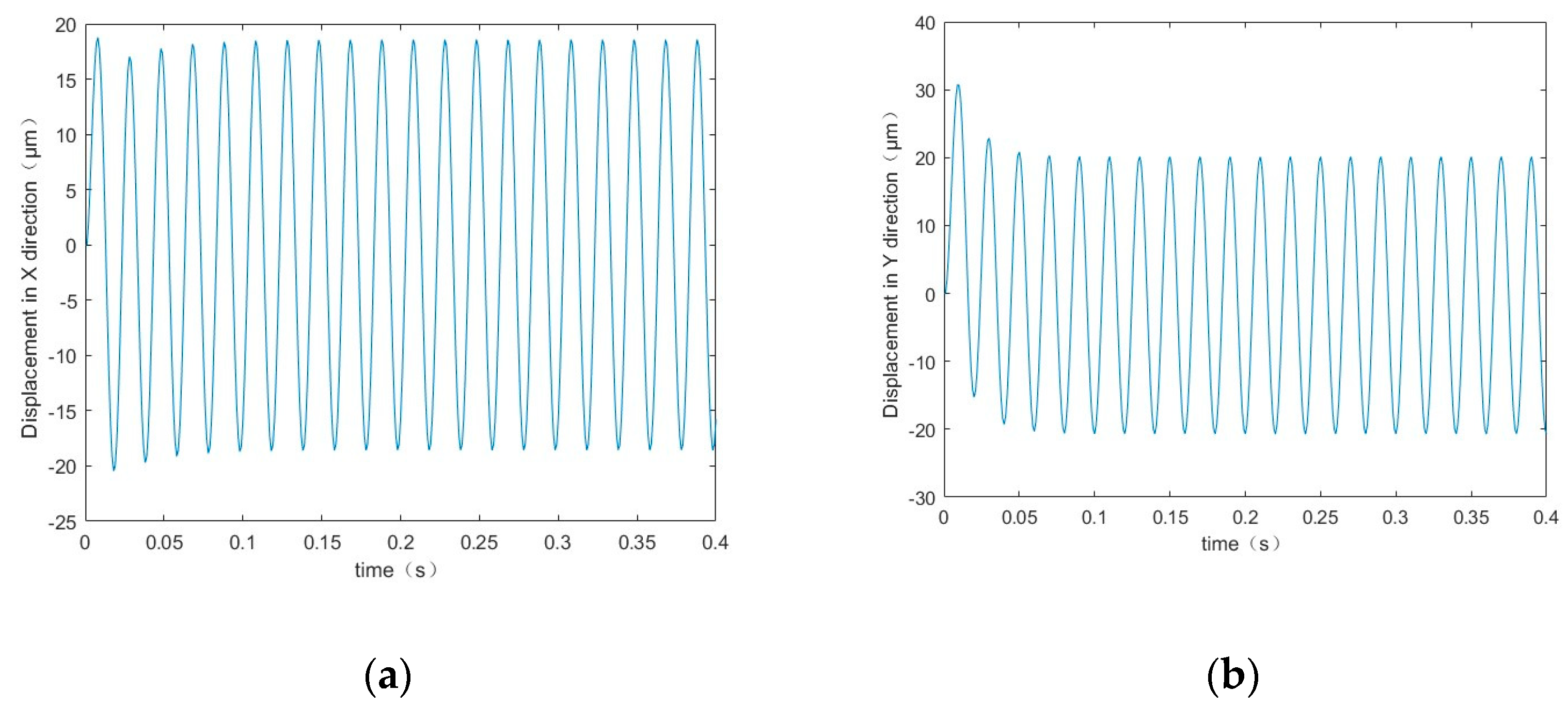
3.2. Thermal Deformation Vibration Simulation Based on Uncertain Parameters

Figure 11a,b illustrates the displacements in the x and y directions of the spindle, taking into account the thermal eccentricity and the inhomogeneous air gap conditions. The initial excitation is solved by addressing the thermal eccentric excitation force and the unbalanced magnetic tension force caused by the air gap inhomogeneity.
As can be seen from Figure 11, the frequency of spindle vibration increases further when considering the effects of both thermal eccentricity and the inhomogeneous air gap simultaneously. Compared to the case of thermal eccentricity only, the amplitude of spindle vibration increases when considering both thermal eccentricity and the inhomogeneous air gap together. However, the vibration displacement after stabilization remains periodic. This is because centrifugal force is the main excitation source in spindle vibration analysis, and unbalanced magnetic tension is an additional excitation source, which leads to an increase in the amplitude of spindle vibration. Thermal deformation causes unbalanced magnetic tension, which introduces extra vibration modes in the spindle. This results in an increase in both the frequency and total energy of the spindle’s vibration in each cycle. As a consequence, the vibration frequency and amplitude also increase. Specifically, the vibration amplitude reaches approximately 43.6 μm in the x direction and 42.9 μm in the y direction.
Figure 12 shows the discrete cell axial trajectory displacements of the shaft protrusion with uncertain parameters. Figure 12a shows the displacement of the shaft in the case of thermal eccentricity of the rotor only; Figure 12b shows the displacement of the shaft in the case of thermal eccentricity of the rotor and the inhomogeneous air gap.
As shown in Figure 12a, solving a multibody dynamics model with uncertain parameters often results in random and unstable outcomes. When considering thermal eccentricity as a random parameter, the existence of mass imbalance in any rigid body within the multibody model, combined with the random degree of mass imbalance on each rigid body, leads to fluctuations in the axial trajectory displacement of the rotor. Only taking into account the amplitude of the axial displacement in the case of rotor thermal eccentricity, the displacement is approximately 41 μm.
As depicted in Figure 12b, when taking into account both thermal eccentricity and air gap inhomogeneity, the spindle vibration becomes more severe due to the compounding effects of these two factors. In particular, mass imbalance causes the spindle to vibrate, while inhomogeneous thermal deformation causes the spindle to deform, thereby affecting the vibration pattern of the spindle. This intricate interplay results in a more intense and unstable spindle vibration, rendering the system more challenging to forecast and regulate. The amplitude of shaft displacement, taking into account both rotor thermal eccentricity and air gap inhomogeneity, is approximately 52 μm.
To more clearly demonstrate the effects of thermal eccentricity and inhomogeneity of the air gap on vibration displacement under uncertain conditions, Figure 13 has been generated.
As shown in Figure 13a, the initial temperature rise leads to a significant increase in vibration displacement, owing to thermal expansion effects. Subsequently, the velocity increase gradually decelerates as the temperature continues to rise, finally stabilizing at 95 °C with a vibration displacement of about 51 μm. This observation implies that the thermal eccentricity effect of the system under high temperatures has achieved saturation.
Inhomogeneous gaps can lead to unbalanced magnetic forces acting on the rotor during its operation, which, in turn, cause vibrations. As shown in Figure 13b, the vibration displacement increases relatively slowly when the air gap inhomogeneity is small. However, once the air gap inhomogeneity reaches a certain level, the increase in vibration displacement accelerates significantly. Ultimately, the vibration displacement is limited by both damping effects and structural constraints working in concert.

4. Results

4.1. Prototype Vibration Experiment

By analyzing the vibration mechanism caused by unbalanced mass and unbalanced magnetic tension, we obtained the vibration characteristics of the BLMS while considering unbalanced mass and unbalanced magnetic tension. To verify the accuracy of the vibration model, we conducted vibration experiments on the BLMS prototype developed by our group.
The experiment was conducted using the experimental prototype of the BLMS, which was smoothly placed on the experimental platform, as shown in Figure 14. The experimental equipment mainly consisted of the BLMS prototype, an eddy current sensor, a multimeter, and a data acquisition card NI-9234, manufactured by National Instruments, located in Austin, TX, USA.
The vibration displacement of the spindle is detected using eddy current sensors and is converted into electrical signals. These signals are then transmitted to a data acquisition card, which converts them into digital signals. The data are then sent to a computer for analysis and processing, resulting in the improved precision and reliability of the experiment. The power supply for the BLMS prototype is divided into two parts—the bearingless motor and the magnetic bearing. The bearingless motor is powered by a 380 V three-phase AC power supply, while the magnetic bearing is powered by a 24 V DC power supply. The displacement sensor uses an eddy current displacement sensor and is powered by a 24 V DC power supply. Figure 15 illustrates the principle diagram for measuring the vibration displacement of the BLMS.
The prototype test examines the dynamic behavior of the spindle by collecting vibration signals from its extended end, subsequently analyzing the impact of thermal deformation. A standard industrial voltage of 380 V/50 Hz is used, with a rotational speed of 3000 r/min and an acquisition time of 400 s. The sensors are arranged vertically to collect vibration signals in both the x and y directions, as shown in Figure 16.

4.2. Vibration Test Analysis

A total of four rounds of vibration displacement data of the spindle protruding end were collected in the test. To simplify the experimental results, we have presented them in Table 3 and Figure 17, considering the large number of data samples.
This test primarily investigates how thermal deformation affects the vibration of the BLMS. Based on the vibration data presented in Table 3 and Figure 17, it is evident that the initial vibration displacement of the spindle is relatively small, with the amplitude of the vibration displacement ranging between 2 μm and 6 μm. At the beginning of the operation, when the motorized spindle is at a low temperature in its initial state, the thermal stress and material deformation can be considered negligible, leading to a smaller amplitude of vibration.
As the spindle continues to operate, its temperature gradually increases, causing the vibration displacement to also increase. At around 220 s of operation, the vibration displacement reaches its peak value and gradually stabilizes. At this point, the spindle’s vibration amplitude is approximately 55 μm. This is because the increase in spindle temperature results in the uneven thermal deformation of the spindle and stator–rotor, leading to thermal eccentricity and an inhomogeneous air gap, which ultimately affect the vibration.
The findings have exposed the constraints of traditional simulation methodologies. Even with the establishment of accurate initial and boundary conditions, there exists a substantial discrepancy between the simulation outcomes and experimental data. In contrast, the outcomes derived from a multibody dynamics model of a motorized spindle with indeterminate parameters demonstrate a closer alignment with experimental data. This model, distinguished by its imprecise parameters, can more precisely depict the irregularity in the air gap, which results from manufacturing mistakes and thermal deformation during practical operation, as well as the effect on vibration that is caused by thermal eccentricity.

5. Discussion

  • Considering the parameter uncertainties that may arise during the service life of the BLMS, this study utilized PC and LM to establish a vibration model based on multibody dynamics and time-varying parameters.
  • Employing the Runge–Kutta algorithm, the motion conditions in the discrete model of the BLMS were solved. Utilizing conventional methods for simulation, the radial vibration displacement of the BLMS was estimated to be approximately 43 μm. Based on a multibody dynamic model of a BLMS with uncertain parameters, the maximum displacement of its central trajectory was calculated to be around 52 μm.
  • An experimental platform was established to conduct experiments on the BLMS prototype. Vibration experiments revealed that the vibration amplitude of the BLMS increased over time, reaching a maximum displacement of approximately 55 μm. The study results indicate that the dynamic model for the BLMS, which includes uncertain parameters, is more consistent with experimental data.
This study is of great significance in ensuring the stable operation of BLMSs. It can also serve as a foundation for optimizing the structural and operating parameters of spindles.

Author Contributions

Conceptualization, J.M. and L.H.; methodology, J.M.; software, L.H.; validation, J.M., L.H. and J.Y.; formal analysis, L.H.; investigation, J.Y.; resources, J.M.; data curation, S.L.; writing—original draft preparation, L.H.; writing—review and editing, L.H.; visualization, J.Y.; supervision, J.Y.; project administration, L.H.; funding acquisition, J.M. All authors have read and agreed to the published version of the manuscript.

Funding

This work was supported by National Natural Science Foundation of China (51505049); the Key Project of Science and Technology Research Project of Chongqing Municipal Education Commission (KJZD-K202101504); the National Key R&D Program Project (2018YFB2002205); and the Project of Graduate Student Innovation Program of Chongqing University of Science and Technology (YKJCX2220318).

Data Availability Statement

Data can be obtained from the corresponding author upon reasonable request.

Conflicts of Interest

The authors declare no competing interests.

References

  1. Dai, Y.; Tao, X.; Li, Z.; Zhan, S.; Li, Y.; Gao, Y. A Review of Key Technologies for High-Speed Motorized Spindles of CNC Machine Tools. Machines 2022, 10, 145. [Google Scholar] [CrossRef]
  2. Yang, Z.; Chen, C.; Chen, F. Progress in the Research of Reliability Technology of Machine Tools. J. Mech. Eng. 2013, 49, 130–139. [Google Scholar] [CrossRef]
  3. Jiang, S.; Zheng, S. Dynamic Design of a High-Speed Motorized Spindle-Bearing System. J. Mech. Des. 2010, 132, 034501. [Google Scholar] [CrossRef]
  4. Gerada, D.; Mebarki, A.; Brown, N.L.; Gerada, C.; Cavagnino, A.; Boglietti, A. High-Speed Electrical Machines: Technologies, Trends, and Developments. IEEE Trans. Ind. Electron. 2014, 61, 2946–2959. [Google Scholar] [CrossRef]
  5. Chen, J.; Zhu, J.; Severson, E.L. Review of Bearingless Motor Technology for Significant Power Applications. IEEE Trans. Ind. Appl. 2020, 56, 1377–1388. [Google Scholar] [CrossRef]
  6. Zhang, Z.; Zhu, H. Decoupling Control on Outer Rotor Coreless Bearingless Permanent Magnet Synchronous Motor Using LS-SVM Generalized Inverse. Prog. Electromagn. Res. M 2022, 111, 65–76. [Google Scholar] [CrossRef]
  7. Knospe, C.R. Active Magnetic Bearings for Machining Applications. IFAC Proc. Vol. 2004, 37, 7–12. [Google Scholar] [CrossRef]
  8. Sun, Y.; Ding, L.; Shi, T.; Liu, X. Finite Element Analysis and Dynamics Charateristic Study for High-Speed Magnetic Suspension Motorized Spindle of CNC Machine Tools. Adv. Mater. Res. 2011, 317–319, 595–599. [Google Scholar] [CrossRef]
  9. Li, Y.; Sheng, L.; Liu, Y.; Tian, X.; Gao, Y. Dynamic Characteristics Analysis of Permanent Magnet Grinding motorized spindle Rotor System under Eccentricity Failure and Stiffness Failure. Int. J. Dyn. Control. 2022, 10, 1349–1360. [Google Scholar] [CrossRef]
  10. Qiao, X.; Hu, G. Modal Analysis and Research on Joint Surface of High Speed Motorized Spindle Unit-Spindle Box. Mach. Sci. Technol. 2016, 20, 425–439. [Google Scholar] [CrossRef]
  11. Bai, X.; Li, J.; Gou, W. Analysis and research on vibration of high-speed motorized spindle in cutting process. J. Qinghai Univ. 2018, 36, 61–79. [Google Scholar] [CrossRef]
  12. Cheng, M.; Gao, F.; Li, Y. Vibration Detection and Experiment of PMSM High Speed Grinding Motorized Spindle Based on Frequency Domain Technology. Meas. Sci. Rev. 2019, 19, 109–125. [Google Scholar] [CrossRef]
  13. Zhang, Y.; Sun, H.; Hu, Z. Analysis of high-speed spindle unbalance vibration behavior and suppression strategy. J. Xi’an Jiao Tong Univ. 2019, 53, 24–29. [Google Scholar]
  14. Chen, D.; Wu, J.; Wang, L. Prediction method of rotary accuracy of motorized spindle based on vibration signal. China Sci. Technol. Sci. 2020, 50, 819–828. [Google Scholar]
  15. He, Y.; Chen, X.; Liu, Z.; Chen, Y. Active Vibration Control of Motorized Spindle Based on Mixed H∞/Kalman Filter Robust State Feedback Control. J. Vib. Control. 2019, 25, 1279–1293. [Google Scholar] [CrossRef]
  16. Bu, W.; Tu, X.; Lu, C.; Pu, Y. Adaptive Feedforward Vibration Compensation Control Strategy of Bearingless Induction Motor. Int. J. Appl. Electromagn. Mech. 2020, 63, 199–215. [Google Scholar] [CrossRef]
  17. Shan, W.; Chen, X. Modelling the Dynamic Performance of Motorized Spindles with Different Bearing Types. Int. J. Simul. Syst. Sci. Technol. 2016, 17, 41–47. [Google Scholar] [CrossRef]
  18. Liu, C.; Yang, Z. The Fem Analysis of Dynamic Characteristics of High Speed Motorized Spindle. Comb. Mach. Tool Autom. Mach. Technol. 2019, 3, 1–4. [Google Scholar] [CrossRef]
  19. Kang, H.; Zhang, C.; Liu, Y. Influence of Time-varying Cutting Load on Dynamic Control Accuracy of Asynchronous Motorized Spindle. Mech. Sci. Technol. 2017, 36, 1367–1374. [Google Scholar] [CrossRef]
  20. Liu, J.; Lai, T.; Tie, G. Influence of thermo-mechanical coupled behaviors on milling stability of high-speed motorized spindles. Precis. Eng. 2018, 52, 94–105. [Google Scholar] [CrossRef]
  21. Zhang, L.; Zha, J.; Zou, C.; Chen, X.; Chen, Y. A New Method for Field Dynamic Balancing of Rigid Motorized Spindles Based on Real-Time Position Data of CNC Machine Tools. Int. J. Adv. Manuf. Technol. 2018, 102, 1181–1191. [Google Scholar] [CrossRef]
  22. Xu, K.; Wang, B.; Zhao, Z.; Zhao, F.; Kong, X.; Wen, B. The Influence of Rolling Bearing Parameters on the Nonlinear Dynamic Response and Cutting Stability of High-Speed Spindle Systems. Mech. Syst. Signal Process. 2020, 136, 106448. [Google Scholar] [CrossRef]
  23. Yang, Z.; Sun, C.; Sun, X.; Sun, Y. An Improved Dynamic Model for Bearingless Induction Motor Considering Rotor Eccentricity and Load Change. IEEE Trans. Ind. Electron. 2022, 69, 3439–3448. [Google Scholar] [CrossRef]
  24. Ye, X.; Yang, Z.; Zhang, T. Modelling and Performance Analysis on a Bearingless Fixed-Pole Rotor Induction Motor. IET Electr. Power Appl. 2019, 13, 251–258. [Google Scholar] [CrossRef]
  25. Bossmanns, B.; Tu, J.F. A Thermal Model for High-Speed Motorized Spindles. Int. J. Mach. Tools Manuf. 1999, 39, 1345–1366. [Google Scholar] [CrossRef]
  26. Liu, T.; Gao, W.; Zhang, D.; Zhang, Y.; Chang, W.; Liang, C.; Tian, Y. Analytical Modeling for Thermal Errors of Motorized Spindle Unit. Int. J. Mach. Tools Manuf. 2017, 112, 53–70. [Google Scholar] [CrossRef]
  27. Chen, X. Thermal Properties of High-Speed Motorized Spindle and Their Effects. Jixie Gongcheng Xuebao 2013, 49, 135. [Google Scholar] [CrossRef]
  28. Liu, D. Finite Element Analysis of High-Speed Motorized Spindle Based on ANSYS. Open Mech. Eng. J. 2011, 5, 1–10. [Google Scholar] [CrossRef]
  29. Tu, X.; Bu, W.; Zeng, Q. Research on the Modelling of a Single-Winding Bearingless Permanent Magnet Brushless DC Motor. J. Phys. Conf. Ser. 2021, 1887, 012049. [Google Scholar] [CrossRef]
  30. Sun, Q.; Ma, C.; Xiao, S.; Niu, L.; Pu, J.; Wu, Y. Analysis of Influence of Uneven Air Gap of Hydrogenerator on Magnetic Field Strength and Rotor Magnetic Pole Stress Change. In 2020 IEEE International Conference on Energy Internet (ICEI); IEEE: Piscataway, NJ, USA, 2020; pp. 147–151. [Google Scholar] [CrossRef]
  31. Zhu, R.; Tong, X.; Han, Q.; He, K.; Wang, X.; Wang, X. Calculation and Analysis of Unbalanced Magnetic Pull of Rotor under Motor Air Gap Eccentricity Fault. Sustainability 2023, 15, 8537. [Google Scholar] [CrossRef]
  32. Xul, J.; Zheng, X.; Zhang, J.; Liu, X. Vibration Characteristics of Unbalance Response for Motorized Spindle System. Procedia Eng. 2017, 174, 331–340. [Google Scholar] [CrossRef]
  33. Huston, R.L. Multibody Dynamics Modeling and Analysis Methods. Appl. Mech. Rev. 1991, 44, 109–117. [Google Scholar] [CrossRef]
  34. Xu, C.; Jiang, S. Dynamic Analysis of a Motorized Spindle with Externally Pressurized Air Bearings. J. Vib. Acoust. 2015, 137, 041001. [Google Scholar] [CrossRef]
  35. Feng, H.; Jiang, S. Dynamics of a Motorized Spindle Supported on Water-Lubricated Bearings. Proc. Inst. Mech. Eng. Part C J. Mech. Eng. Sci. 2016, 231, 459–472. [Google Scholar] [CrossRef]
  36. Guo, D.; Chu, F.; Chen, D. The Unbalanced Magnetic Pull and Its Effects on Vibration in a Three-Phase Generator with Eccentric Rotor. J. Sound Vib. 2002, 254, 297–312. [Google Scholar] [CrossRef]
  37. Xu, J. Multibody Dynamics Modeling of Wind Turbines and Its Application. Ph.D. Thesis, University of Chinese Academy of Sciences, Beijing, China, 2021. [Google Scholar]
  38. Cho, S.; Jeon, K.; Kim, C.W. Vibration Analysis of Electric Motors Considering Rotating Rotor Structure Using Flexible Multibody Dynamics-Electromagnetic-Structural Vibration Coupled Analysis. J. Comput. Des. Eng. 2023, 10, 578–588. [Google Scholar] [CrossRef]
  39. Sheng, L.; Sun, Q.; Ye, G.; Li, W. Dynamic Analysis of Grinding motorized spindle Bearing-Rotor System under Eccentric Action. J. Adv. Mech. Des. Syst. Manuf. 2023, 17, 28. [Google Scholar] [CrossRef]
Figure 1. The structure of the BLMS.
Machines 12 00458 g001
Figure 2. Internal temperature field of the BLMS.
Machines 12 00458 g002
Figure 3. Thermal deformation of the stator and the rotor of the BLMS.
Machines 12 00458 g003
Figure 4. Schematic of the rotor under thermal eccentric conditions.
Machines 12 00458 g004
Figure 5. Schematic diagram of the uneven thermal deformation of the rotor.
Machines 12 00458 g005
Figure 6. Schematic of the discrete model of the spindle.
Machines 12 00458 g006
Figure 7. Variation in spindle displacement without considering the influence of external factors. (a) X direction; (b) Y direction.
Machines 12 00458 g007
Figure 8. Axis displacement trajectory of spindle end under deterministic parameter definition.
Machines 12 00458 g008
Figure 9. Variation in spindle displacement considering only the case of thermal eccentricity of the spindle. (a) X direction; (b) Y direction.
Machines 12 00458 g009
Figure 10. Axis displacement trajectory of spindle end under deterministic parameter definition.
Machines 12 00458 g010
Figure 11. Variation in spindle displacement considering thermal eccentricity and inhomogeneous air gap. (a) X direction; (b) Y direction.
Machines 12 00458 g011
Figure 12. Axis displacement trajectory of spindle end under uncertain parameter definition.
Machines 12 00458 g012
Figure 13. Impact of temperature (a) and inhomogeneous gaps (b) on amplitude in uncertain conditions.
Machines 12 00458 g013
Figure 14. BLMS test prototype.
Machines 12 00458 g014
Figure 15. Measurement schematic.
Machines 12 00458 g015
Figure 16. Experimental scheme of the vibration of a BLMS prototype.
Machines 12 00458 g016
Figure 17. Experimental results of vibration of the BLMS.
Machines 12 00458 g017
Table 1. Heat generation rate of the BLMS.
Heat Generation Rate (kW/m3)Numerical Value
Bearingless motor stator243,851
Bearingless motor rotors226,159
Radial magnetic bearing copper loss10,008
Radial magnetic bearing iron loss163,516
Copper loss in axial magnetic bearings52,135
Axial magnetic bearing iron loss137,788
Rotor wind loss10,623
Table 2. Convective heat transfer coefficient of the BLMS.
Convective   Heat   Transfer   Rate   ( W / m 3 · ° C )Numerical Value
Bearingless motor rotor with air231.17
Thrust magnetic bearing rotor with air179.84
Radial magnetic bearing rotor with air137.81
BLMS outer surface and air9.7
Table 3. Vibration test parameters and peak amplitude.
Experiment NumberActivation MethodNumber of Revolutions per MinuteRunning TimePeak Amplitude (μm)
1380 V voltage start3000 r/min400 sX:57 Y:57
2380 V voltage start3000 r/min400 sX:56 Y:57
3380 V voltage start3000 r/min400 sX:57 Y:56
4380 V voltage start3000 r/min400 sX:56 Y:55
Disclaimer/Publisher’s Note: The statements, opinions and data contained in all publications are solely those of the individual author(s) and contributor(s) and not of MDPI and/or the editor(s). MDPI and/or the editor(s) disclaim responsibility for any injury to people or property resulting from any ideas, methods, instructions or products referred to in the content.

