Article

Impact of Installation Deviations on the Dynamic Characteristics of the Shaft System for 1 Gigawatt Hydro-Generator Unit

1
China Three Gorges Construction Engineering Corporation, Liangshan 615421, China
2
State Key Laboratory of Hydroscience and Engineering, Department of Energy and Power Engineering, Tsinghua University, Beijing 100084, China
3
S.C.I. Energy, Future Energy Research Institute, 8706 Zurich, Switzerland
*
Author to whom correspondence should be addressed.
Machines 2024, 12(7), 473; https://doi.org/10.3390/machines12070473
Submission received: 26 June 2024 / Revised: 4 July 2024 / Accepted: 11 July 2024 / Published: 12 July 2024

Abstract

:
The shaft system, transferring the kinetic energy of water flow into electrical energy, is the most critical component in hydropower plants. Installation deviations of the shaft system for a giant hydro-generator unit can have significant impacts on its dynamic characteristics and overall performance. In this investigation, a three-dimensional geometry of the shaft system of an operating hydro-generator unit prototype with a rated power of 1 GW is established. Then, the calculation model of the shaft system is generated accordingly with tetrahedral and hexahedral elements. By applying different boundary conditions, the finite-element method is used to analyze the influences of installation deviations, including shaft radial misalignment and angular misalignment, on the dynamic characteristics of the shaft system. The calculation results reveal that the installation deviations change the natural frequencies, critical speeds, and mode shapes of the shaft system to a certain degree. The natural frequencies of the backward precession motion with installation deviations are reduced by 23% and 38% for the rated speed and the maximum runaway speed. Furthermore, for the forward precession motion, they increased by 30% and 48%, respectively. The critical speeds for the shaft system with radial and angular deviations are 3.2% and 3% larger than the critical speed of the shaft system without any mounting deviations. The radial and angular installation deviations below the maximum permissible values will not result in the structural performance degradation of the 1 GW hydro-generator shaft system. The conclusion drawn in this research can be used as a valuable reference for installing other rotating machinery.

1. Introduction

In recent decades, hydropower, which uses water energy to generate electricity, has become an important and well-established source of renewable energy globally. Hydropower, as a base load power source that provides reliable and predictable power to the grid and has become an environmentally friendly option for many countries to reduce greenhouse gas and carbon emissions and combat climate change [1]. Hydropower is by far the largest renewable source of electricity and generates more electricity than all other renewable technologies combined [2]. Large-scale hydropower projects provide stable power for energy security and stabilize the national grid. Infrastructure development associated with these projects can have positive knock-on effects on various sectors of the economy. Large-scale hydropower projects require a large number of high-quality large and giant hydroelectric generating units.
Francis turbines are known for their high efficiency, especially in medium–high head applications, and their efficiency can be over 95%. Francis turbine units have been widely used and studied over many decades, making them a mature and proven technology [3]. Francis turbines perform best when they have a head of between 100 and 300 m [4]. The accumulated knowledge and experience have contributed to the reliability and predictability of their performance. Their ability to operate efficiently across a range of water flow rates and heads makes them suitable for various hydropower projects.
The shaft systems of Francis hydro-generator units are the core rotating equipment in the hydropower plants. The shaft system usually consists of several interconnected parts, e.g., the generator rotor, the Francis runner, the turbine shaft, and the generator shaft [5]. The shaft system transmits mechanical power from the rotating turbine runner driven by water to the generator rotor, which in turn generates electrical power. The turbine shaft and generator shaft are assembled with a number of connecting bolts during the installation in the power plant. The designed model of shaft system of the hydro-generator unit is an idle model without any deviations, but the radial installation deviation and angular installation deviation between the turbine shaft and the generator shaft in the power plant can not be avoided—although, the deviation values are very small compared to the dimensions of the shaft system.
Installation deviations of the turbine and generator may change the natural frequencies and critical speed of the hydro-generator shaft system [6], and can cause severe vibrations in the shaft system [7]. Gustavsson R. explored the influence of generator radial deviation on the strong unbalanced magnetic pull of the shaft system for a hydro-generator unit and found that the electromagnetic forces can, in some situations, have a strong influence on the rotor dynamics; they suggested carefully guaranteeing the radial deviation between the center line of generator spider hub and the center line of generator rim during installation [8]. Kahraman G. carried out the study of the balancing effect of the radial and axial alignment of the hydraulic turbine shaft; they researched the vibration failure caused by the unbalancing effect in the hydraulic turbine shaft system, and provided a new nonlinear, proportional-order mathematical model to ensure specificity in the diagnosis and prediction of faults in hydropower plants [9]. Lundstrom L. et al. researched the huge eccentricity forces acting on the hydro-generator shaft system with a 74 MVA synchronous generator and found that the large eccentricity forces resulting from the generator radial deviation can lead to expensive damage and failures of the shaft system [10].
Taking account of the radial deviations of the generator rotor, Xu Y. et al. investigated the influence of nonlinear unbalanced magnetic pull on the radial vibration of a large hydro-generator shaft system [11]. Rondon. D. et al. conducted numerical simulations of a hydropower unit and found that the uneven distribution of electromagnetic forces in the deformed generator rotor of the hydropower unit can produce an unbalanced magnetic pull. The unbalanced magnetic pull can result in a high force on the generator of the shaft system, leading to the risk of fatigue, and shortening the life of the hydropower unit [12]. Cardinali, R. et al. developed a nonlinear model of the hydro-generator shaft system, considering the deviations of the boundary conditions, and calculated bending vibrations and natural frequencies of the shaft system to ensure that the shaft system can withstand axial and radial loads during operation [13]. Based on the experimental data over the last three decades, Brito Junior, G.C. et al. found that the boundary condition deviations of the shaft system for 20 hydropower machines can have frequent, significant, and unpredictable changes, which significantly reduced the natural frequencies and the critical speeds of the shaft system [14]. Boyko A. et al. presented the disaster and damages to the shaft systems of the large hydropower units in the Sayano-Shushenskaya hydropower plant. The 920 tonne shaft system was shot out of its seat by the water and destroyed the powerhouse [15]. So, the hydro-generator shaft system must be reasonably designed and precisely manufactured and installed to ensure its reliability, durability, and efficient long-term operating performance.
In order to analyze the structural model behavior and rotor dynamics of the hydro-generator shaft system, the transfer matrix method (TMM) and the finite-element method (FEM) are usually used among experts. TMM, a simplified method, employs a one-dimensional model of the rotating shaft system in a hydroelectric generation unit to predict the dynamic characteristics of the shaft systems. Feng F. et al. provided a detailed calculation of the critical speed and vibration modes with TMM and studied the influence of the stiffness of the guide bearings on the dynamic characteristics of the shaft system of a pump–turbine unit [16]. Wang Z. et al. performed a rotordynamics analysis of the shaft system for a middle-scale Francis hydro-generator unit at the design phase using TMM and evaluated the dynamic responses of the shaft system under different load cases [17]. Barbosa R. developed a computer routine with TMM to predict the bending critical speeds of shaft systems of two hydro-generator units, and the code can be used for the preliminary analysis of the rotor dynamics at the early design phase of hydro-generator shaft systems [18]. TMM simplifies the three-dimensional (3D) components of the shaft system into line elements and mass points, so the calculation results differ significantly from the actual situation. To improve the accuracy of calculation results, the FEM was adopted to perform the dynamic characteristics analysis of the full 3D shaft systems of various types of hydro-generator units with Bulb turbines and pump–turbines. Cao J. et al. calculated the natural frequencies of the horizontal shaft Bulb hydro-turbine unit, with a full 3D finite-element calculation model, and checked the possible resonance problems for the turbine shaft system [19]. Egusquiza E. et al. presented the natural frequencies and mode shapes response of a full 3D shaft system for a 110 MW pump–turbine unit, which was calculated via finite-element analysis [20]. The Bulb turbine and pump–turbine have totally different geometries than the Francis turbines and present different dynamic characteristics of the shaft systems as the Francis turbine–generator units. Furthermore, these investigations did not take into consideration the impact of radial and angular installation deviations between the turbine shaft and generator shaft on the dynamic behavior of the hydro-generator shaft systems.
Some researchers have studied the impacts of axial and radial installation deviations of the shaft system components on the hydraulic forces for large Francis turbine–generator units. Liu Y. et al. discovered the axial installation deviations of the large Francis runner have a great effect on the hydraulic axial force on the runner’s outer surfaces, but a smaller impact on the runner’s inner outer surfaces. As the runner axial installation deviation increases, the total hydraulic axial force of the shaft system gradually decreases [21]. Wang Y. found that as the radial installation deviation of the large Francis runner increases, the radial unbalance forces acting on the shaft system increases linearly [22]. Zhang Y. reported that the installation deviation for the bearings has a significant influence on the modal behavior of the shaft systems of large hydro-turbine generator units [23]. However, the influences of the installation deviations between the turbine shaft and generator shaft were not studied. In order to gain a deeper understanding of the effects of shaft installation deviations on the shaft systems of large hydro-generator units and to provide valuable technical guidance for different hydropower plants during the insulation process, it is extremely important to study the impacts of the radial and angular installation deviations between the turbine shaft and the generator shaft on the modal behavior and rotor dynamics of the shaft systems.
To achieve this goal, the world’s largest Francis units, rated at 1 GW, are used in this study as state-of-the-art representatives of Francis turbine generator units. First, the complete 3D computer-aided design (CAD) geometry of the shaft system of turbine–generator units is constructed, precisely based on the installed prototype in the hydropower plant. Then, the finite-element (FE) meshes are generated according to the CAD geometry of the shaft system, integrating various components. Next, the modal analysis and the rotordynamic analysis of the shaft systems without shaft installation deviations are conducted to obtain the mode shapes and natural frequencies, as well as the critical speed. Afterward, the impacts of the shaft angular installation deviation and shaft axial installation deviation on the dynamic behavior and rotor dynamics of the shaft system are investigated in detail, and the results are compared to the results obtained without installation deviations. The analysis approach and conclusions for the 1 GW shaft systems also apply to other large-, medium-, and small-scale Francis hydro-generator units.

2. Numerical Calculation Theory of the Hydro-Generator Shaft System

2.1. Modal Analysis

The turbine installation elevation of this hydropower plant is about 570 m above sea level, and the rated power of a single hydro-generator unit is 1 GW. Table 1 lists the parameters of the hydro-generator unit.
A full 3D model of the shaft system for the 1 GW hydro-generator unit has been established on the basis of ensuring that the modeling is consistent with the dimensions of the prototype installed in the hydropower plant (Figure 1). The shaft system of the 1 GW hydro-generator unit mainly includes a Francis runner, a generator rotor, a turbine shaft, a generator shaft, shaft-connecting bolts, and other components. The shaft system is supported by the generator guide bearings, the turbine guide bearing, and the thrust bearing. Since the 3D model of the shaft system is very complex, a more regular geometric model can be obtained by simplifying the non-important parts.
The density of the steel structure of the shaft system is 7850 kg m 3 , the modulus of elasticity is 210 GPa, and the Poisson’s ratio is 0.3. The total mass of the shaft system of the 1 GW hydro-generator unit is 2680.5 tonnes, and the detailed mass values of structural components of the shaft system are shown in Table 2.
The structural inherent characteristics of the shaft systems of the Francis turbine generator units are the basis for studying their dynamic performance. A modal analysis of hydro-generator shaft systems can determine their dynamic characteristics, such as the natural frequency and the mode shapes, and these parameters are essential for predicting resonance conditions of the hydro-generator units and ensuring their stable operation. Precise calculation of the dynamic characteristics of the shaft system can effectively avoid the occurrence of resonance in key components of the hydro-generator unit.
The typical structural governing equation of the shaft system of a hydro-generator unit can be described as follows:
M φ ¨ + C φ ˙ + K φ = F
where φ is the displacement vector of the shaft system, while φ ˙ and φ ¨ are the velocity vector and acceleration vector; M denotes the mass matrix of the shaft system, while C and K the damping matrix and stiffness matrix; F denotes the forces applied on the shaft system considering the impacts of installation deviations.
The presence of water around the hydro-turbine increases the effective mass of the turbine runner, which affects the natural frequencies and dynamic responses of the hydro-generator shaft system. The governing equation of the shaft system considering the added mass effect of water can be written as follows:
( M + M w ) φ ¨ + C φ ˙ + K φ = F + F w
where M w denotes the added effective mass of water; F w denotes the force of water applied on the shaft system.
The dynamic characteristics of the 1 GW hydro-generator shaft system depend on the structural properties and boundary conditions of the unit. The installed turbine runner is submerged in water and the effect of the additional mass of water around the runner on the dynamic characteristics of the shaft system needs to be considered.
The installed shaft system is radially restrained by the upper generator bearing, the lower generator bearing, and the turbine bearing, and is axially restrained by the thrust bearing. The high-pressure oil films in the guide and thrust bearings keep the shaft system operating within the permissible range of bearing clearances. According to the obtained data from the power plant, the equivalent stiffness of the upper generator bearing and the lower generator bearing is 7 × 10 9 N m 1 , and the stiffness of the turbine bearing is 5 × 10 9 N m 1 . The equivalent stiffness of the thrust bearing oil film is 8 × 10 10 N m 1 .
The damping value of the shaft steel structures is very small and can be ignored when performing the modal analysis. The structural free vibration Equation (Equation (3)) and its harmonic form solution (Equation (4)) can be used to calculate the mode shapes and natural frequencies of the shaft system of the hydro-generator unit.
( M + M w ) φ ¨ + K φ = 0
φ = Φ e j ω t
where e, j, and t are the Euler’s number, unit imaginary number, and time, respectively. Φ is the mode shape vector with the natural frequency ω .

2.2. Rotordynamics Analysis

Rotordynamics can analyze the dynamic behavior of the rotating shaft system for the hydro-generator unit, considering factors such as installation deviations, mass unbalance, and gyroscopic effects. Accurate rotordynamics analysis can ensure the reliability and longevity of the shaft system. In order to accurately assess the effect of rotational speed on the dynamic behavior of the shaft system, rotordynamics were analyzed for the shaft system with speeds ranging from 0 rpm to 300 rpm and without installation deviation. The rotation direction of the shaft system is clockwise from the top view (Figure 2).
The following equation of motion can be used to analyze the rotordynamics of the shaft system of the hydro-generator unit:
( M + M w ) φ ¨ + ( C + C r ) φ ˙ + ( K K r ) φ = F + F w
where C r is the Coriolis effect matrix related to the rotational speed, and K r is the rotation softening effect matrix.

3. Dynamic Characteristics Analysis and Discussions

3.1. Modal Analysis of the Shaft System without Installation Deviation

Firstly, the modal characteristics of the 1 GW hydro-generator shaft system at a standstill and without installation deviation were analyzed to obtain basic results of the unit as a reference.
Tetrahedral and hexahedral elements are the primary element types used to discretize geometric models and generate the corresponding FE models. Hexahedral elements can achieve similar accuracy with fewer elements compared to tetrahedral elements, but they are less flexible than tetrahedral elements when dealing with highly irregular and sophisticated geometries. The geometric topologies of the generator, generator shaft, and turbine shaft are simple; hexahedral meshes are suitable here and can achieve similar accuracy with fewer elements compared to tetrahedral meshes. The design of Francis runners is critical in optimizing the efficiencies and performance of the unit, and the turbine blades are usually uniquely shaped in a 3D twist to enable them to efficiently convert fluid energy into mechanical energy. The established FE model of the 1 GW hydro-generator shaft system is shown in Figure 3.
Considering the water-added mass and the stiffness of the radial and axial bearings, the calculation results show that the first-order (1st-order) mode shapes of the shaft system are a primary bending vibration mode (Figure 4). The first bending mode of the shaft system is mainly reflected in the vibration on the generator, which has the largest vibration displacement, while the main shaft and turbine runner have almost no motion. The analysis shows that the natural frequency of the shaft system corresponding to the first vibration mode is 5.68 Hz, corresponding to 340.8 rpm, which is higher than the rated rotational speed ( n r ), 111.1 rpm, and the maximum runaway speed ( n m a x . ), 202 rpm.

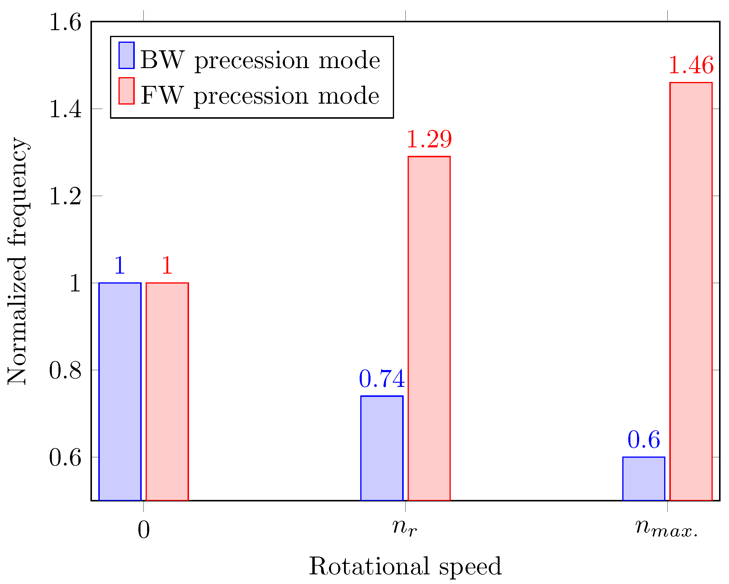
3.2. Rotordynamics Analysis of the Shaft System without Installation Deviation

As presented in Figure 5, due to the Coriolis effect caused by the rotation of the shaft system, the natural frequency of the shaft system at a given rotational speed is divided into two different values. Accordingly, the motion of the shaft system becomes a backward (BW) precession motion and a forward (FW) precession motion. For the BW precession motion, the rotating direction of shaft precession is opposite to the rotation direction of the shaft system, and the 1st-order natural frequency decreases as the speed increases. For the FW precession motion, the rotating direction of the shaft precession is the same as the rotation direction of the shaft system, and the 1st-order natural frequency increases as the speed increases.
Figure 5 shows the natural frequencies of BW precession motion at the rated rotating speed n r (111.1 rpm) and the maximum runaway speed n m a x . (202 rpm) are 0.74 and 0.6 times the natural frequency for the shaft system at 0 rpm, respectively. The natural frequencies of FW precession motion at the rated rotating speed n r and the maximum runaway speed n m a x . are 1.29 and 1.46 times the natural frequency for the shaft system at 0 rpm, respectively.
Taking the natural frequency for the shaft system at 0 rpm ( f 0 ) without deviations as a reference, the changes of the natural frequencies at various rotating speeds can be calculated with the frequency increase rate (FIR) as expressed in Equation (6).
F I R ( % ) = 100 × ( f n f 0 ) / f 0
As demonstrated in Figure 6, the natural frequencies of BW precession motion at the rated speed n r and the maximum runaway speed n m a x . have reduced by 26% and 40%, respectively. The natural frequencies of FW precession motion at the rated speed n r and the maximum runaway speed n m a x . have increased by 29% and 46%, respectively.
The FW and BW vibration modes present the same pattern but rotate in opposite directions. Figure 7 presents the BW vibration mode in a revolution of the shaft system without installation deviations. It can be seen that the BW vibration mode of the shaft system is also mainly reflected in the oscillation vibration of the generator. The structural stiffness of the support structures in the middle of the generator rotor is much lower than the stiffness of the generator poles, so the maximum displacement is located at the generator poles. In one rotating revolution of the shaft system, half of the generator rotor moves upward and half moves downward, so the motion of the generator rotor is one nodal diameter (1 ND) vibration pattern.
Figure 8 illustrates the Campbell diagram of the 1 GW hydro-generator shaft system, which presents the dynamic characteristics of the rotating shaft system in terms of a plot of natural frequencies versus the rotating speeds. In the Campbell diagram, 1 X denotes the fundamental frequency corresponding to the shaft rotational speed. It can be seen that the natural frequencies of FW and BW precession motions show a slightly nonlinear variation with rotational speed. The variations of natural frequencies of FW ( f F W ) and BW precession motion ( f B W ) with rotating speed (n) can be expressed by the regression equations Equations (7) and (8).
f F W = 0.00002 n 2 + 0.0146 n + 5.68
f B W = 0.00001 n 2 + 0.0154 n + 5.68
The critical speed in Figure 8 is the speed at which the natural frequency of the shaft system is equal to its rotational frequency, and it is an important parameter in the mechanical analysis and design of large hydro-generator unit units. The calculation results show that the first critical speed of the shaft system without installation deviations is 202.5 rpm, which is higher than the rated speed of n r (111.1 rpm) and also higher than the maximum runaway speed n m a x . (202 rpm), so the 1 GW hydro-generator unit will not reach the first critical speed of the shaft system during operation.

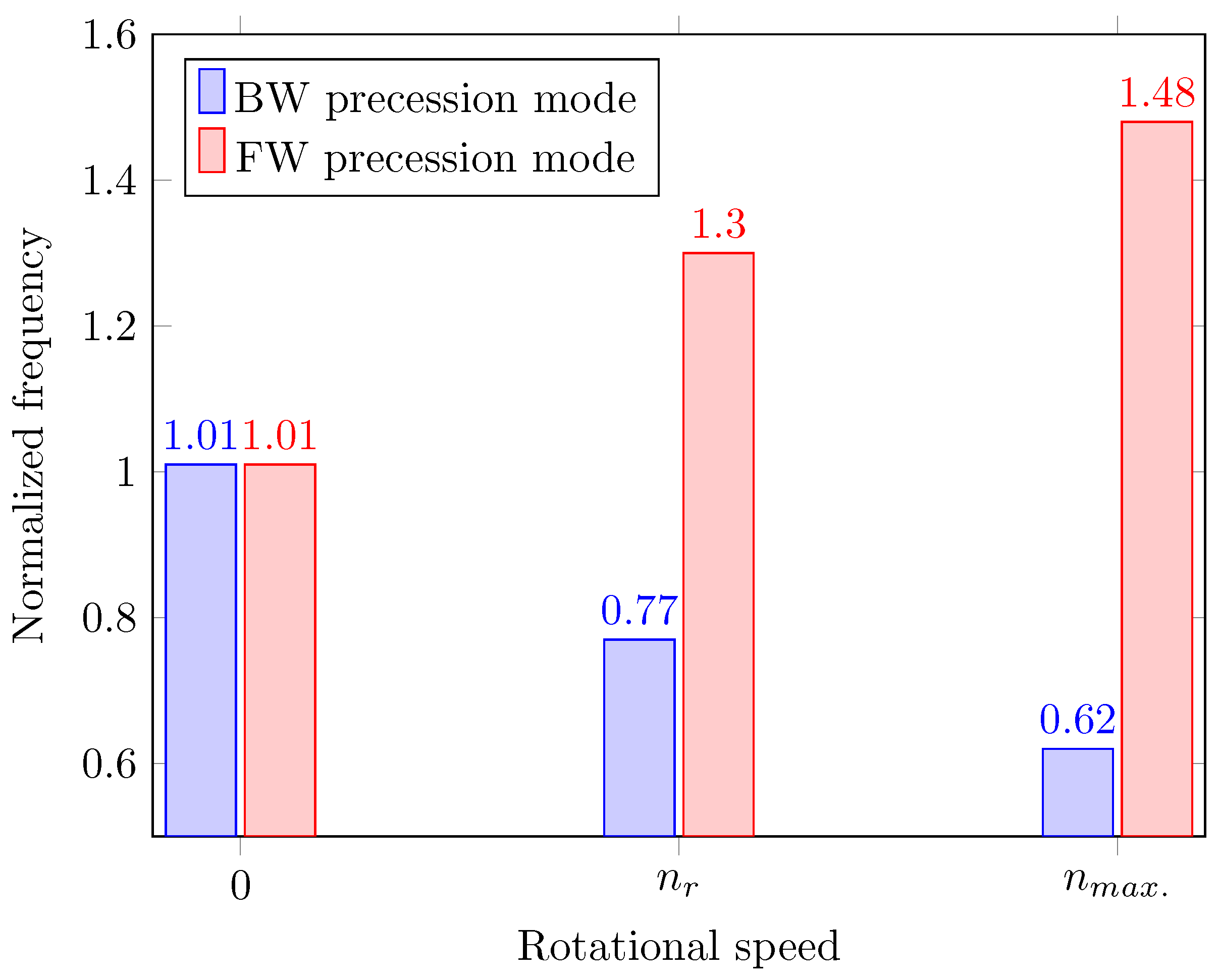
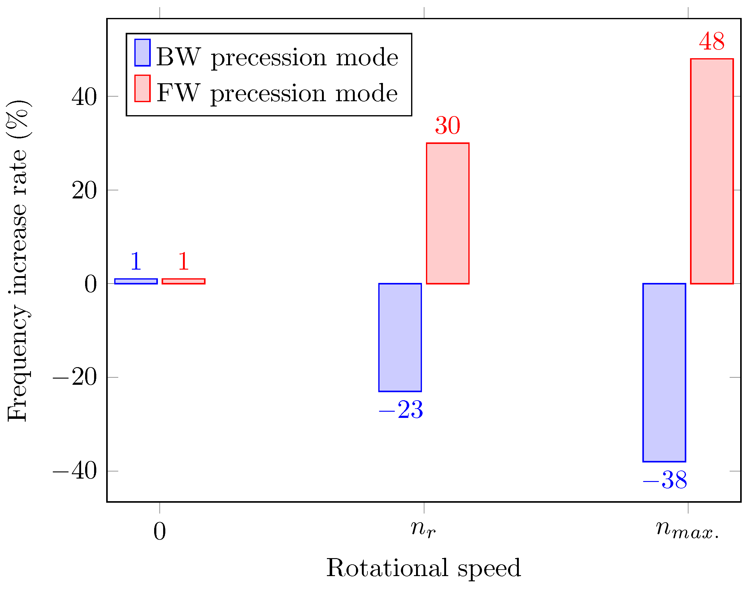
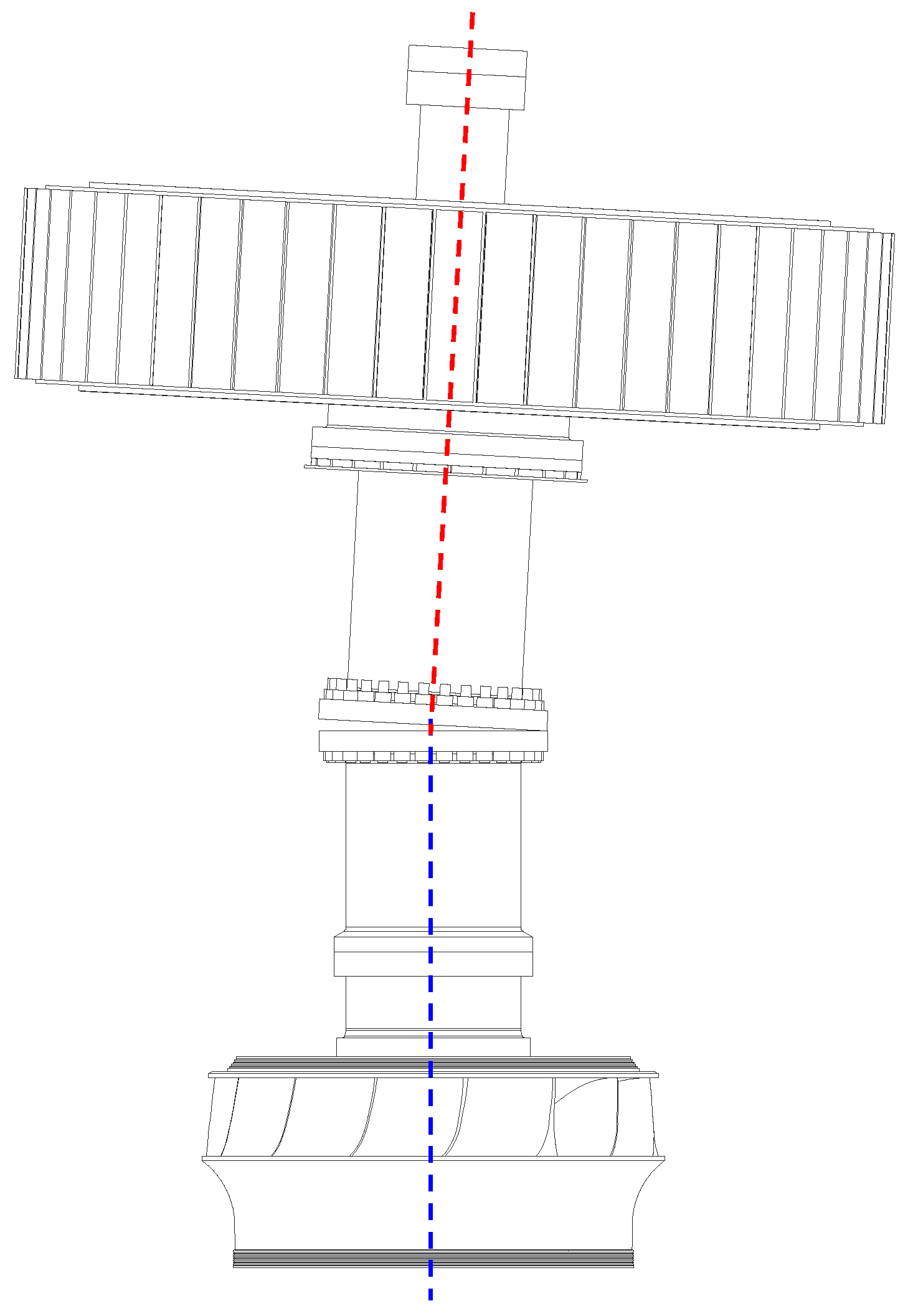
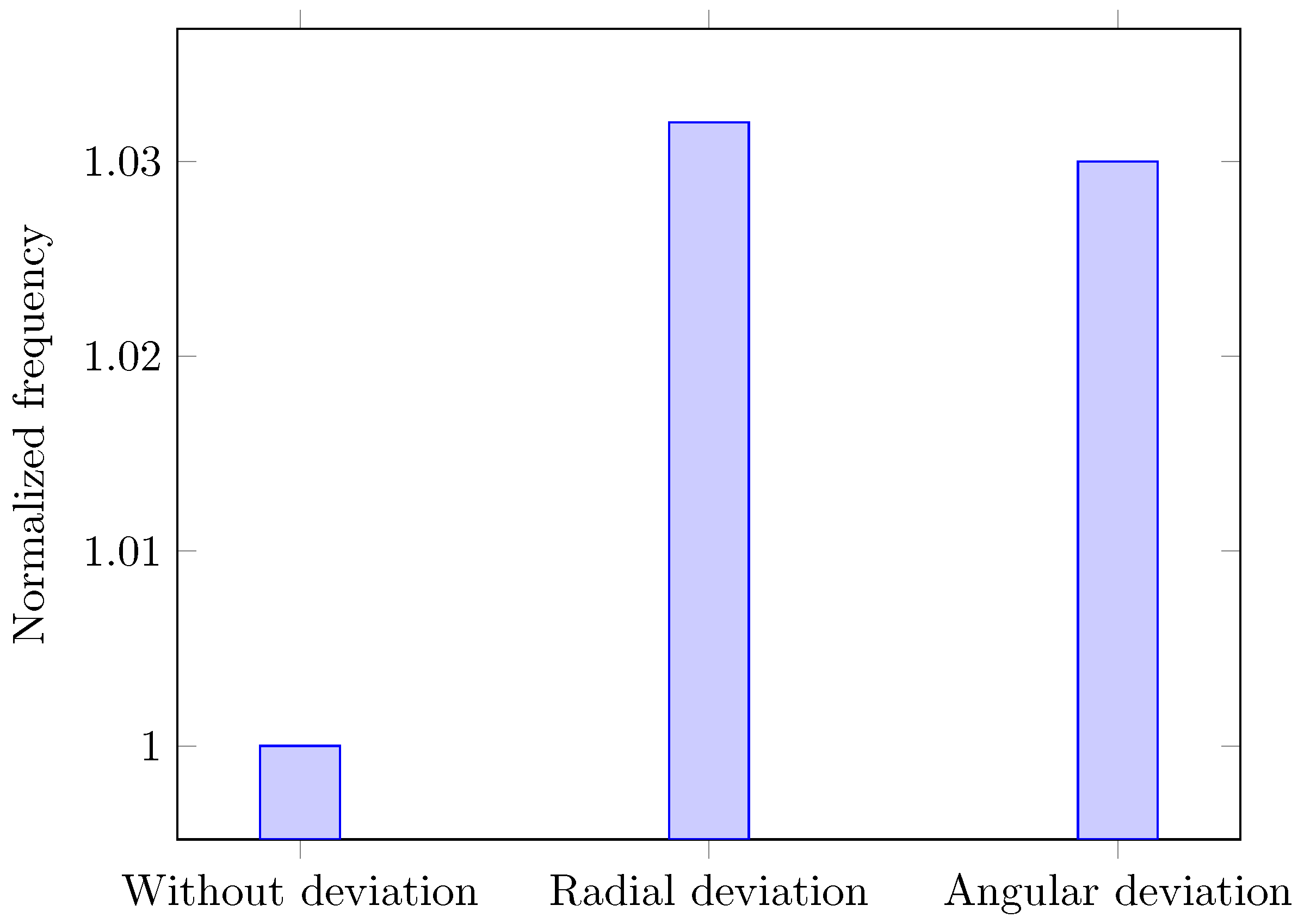
3.3. Structural Dynamic with Shaft Radial Installation Deviation

During the installation of the hydro-turbine generator shaft system, radial deviation may exist between the turbine shaft and the generator shaft (Figure 9). Shaft radial installation deviation can cause rotor imbalance because the offset rotating parts will cause additional centrifugal force when the shaft system rotates. These centrifugal forces may cause increased vibration and reduced stability of the shaft system, thus affecting the performance and service life of the shaft system.
Following the installation guidelines of hydropower operators for 1 GW-class hydro-generator units, the maximum permissible radial installation deviation between the generator shaft and the turbine shaft is 0.5 mm. In order to accurately assess the impact of rotational speed on the shaft system’s dynamic behavior, rotordynamics were analyzed in the speed range of 0 rpm to 300 rpm for the shaft system with a shaft radial installation deviation of 0.5 mm.
The 1st-order vibration mode for the shaft system with shaft radial deviation shows a similar vibration pattern as that without deviations (Figure 7). Similar to the results for the shaft system without mounting deviation, for the BW precession motion with shaft radial installation deviation, the rotating direction of shaft precession is opposite to the rotation direction of the shaft system; the 1st-order natural frequency decreases as the speed increases. For the FW precession motion, the rotating direction of shaft precession is the same as the shaft system’s rotation direction, and the 1st-order natural frequency increases as the speed increases.
Figure 10 shows that, at 0 rpm, the natural frequency of the 1st-order vibration mode with radial installation deviation is 1.01 times that without installation deviation. For the BW precession motion with shaft radial installation deviation at the rated rotating speed n r (111.1 rpm) and the maximum runaway speed n m a x . (202 rpm) are 0.77 and 0.62 times the natural frequency of the shaft system at 0 rpm without installation deviation, respectively. The natural frequencies of FW precession motion at the rated rotating speed n r and the maximum runaway speed n m a x . are 1.3 and 1.48 times the natural frequency of the shaft system at 0 rpm without installation deviation, respectively.
As demonstrated in Figure 11, the natural frequency of the 1st-order vibration mode with radial deviation at 0 rpm is 1% higher than that without installation deviation and the natural frequencies of BW precession motion at the rated speed n r (111.1 rpm) and the maximum runaway speed n m a x . (202 rpm) have reduced by 23% and 38%, respectively. The natural frequencies of FW precession motion at the rated speed n r (111.1 rpm) and the maximum runaway speed n m a x . (202 rpm) have increased by 30% and 48%, respectively.
The Campbell diagram of the shaft system with radial mounting deviation is plotted in Figure 12. The regression equations Equations (9) and (10) describe the nonlinear relations between the natural frequencies for FW ( f F W ) and BW precession motion ( f B W ) with the rotating speed (n).
f F W = 0.00002 n 2 + 0.0141 n + 5.74
f B W = 0.00003 n 2 + 0.0182 n + 5.74
As presented in Figure 12, the critical speed of the shaft system with radial installation deviation is 209 rpm, which is higher than that without installation deviations (202.5 rpm). The critical speed of the shaft system with radial installation deviation is also above the rated speed of n r (111.1 rpm) and the maximum runaway speed n m a x . (202 rpm). The results reveal that a radial mounting deviation of 0.5 mm in the shaft system of 1 GW hydroelectric turbine generator units slightly enhances the structural rotor dynamics of the shaft system during operation.

3.4. Dynamic Characteristics with Shaft Angular Installation Deviation

Angular deviations between the axes of the turbine shaft and the generator shaft may also occur during the installation of the 1 GW hydro-generator shaft system (Figure 13), resulting in the deterioration of the performance of the shaft system. According to the installation guidelines, the maximum allowable angular installation deviation between the turbine shaft and the generator shaft is 0.01 degrees.
The rotordynamics characteristics of the shaft system with shaft angular mounting deviation are investigated with a speed range from 0 rpm to 300 rpm. The FIRs of the shaft system without and with mounting deviations are compared in Figure 14.
As the results of the shaft system with radial installation deviation, the 1st-order vibration mode of the shaft system with shaft angular mounting deviation has a similar pattern to that without mounting deviation (Figure 7). The natural frequency of the 1st-order vibration mode with angular installation deviation at 0 rpm is also higher than that without installation deviation. The natural frequencies of BW precession motion with angular installation deviation at the rated rotating speed n r (111.1 rpm) and the maximum runaway speed n m a x . (202 rpm) have also reduced by 23% and 38%, respectively, when compared with the frequency at 0 rpm without installation deviation. For the FW precession motion, they have increased by 30% and 48%, respectively.
The Campbell diagram of the shaft system with angular mounting deviation is shown in Figure 15 with a critical speed of 208.5 rpm. The nonlinear relationships between the natural frequencies and the rotational speeds (n) of the FW ( f F W ) and BW progression modes ( f B W ) are listed in Equations (11) and (12).
f F W = 0.00002 n 2 + 0.0146 n + 5.74
f B W = 0.00003 n 2 + 0.0189 n + 5.74
The critical speeds of the shaft system without and with mounting deviations are illustrated in Figure 16; they are beyond the rated speed of n r (111.1 rpm) and the maximum runaway speed n m a x . (202 rpm) of the unit. The critical speeds of the shaft system with radial and angular installation deviations are 3.2% and 3% higher than those without installation deviation. Therefore, radial and angular installation deviations below the maximum permissible values do not cause a degradation of the rotor dynamics performance of the shaft system.

4. Conclusions

The full three-dimensional CAD and FE models of the 1 GW hydro-generator shaft system—including the turbine runner, the generator rotor, the generator shaft, and the turbine shaft—have been constructed. The impacts of radial and angular installation deviations on the structural modal behavior and rotor dynamics performance have been assessed in detail.
The results reveal that first-order mode shapes of the shaft system with and without installation deviations have a similar vibration pattern, with the largest vibration displacement occurring for the generator, while the main shaft and turbine runner have almost no motion. The motions of the generator rotor rotating one revolution at various speeds exhibit a nodal diameter (1 ND) vibration pattern, i.e., half of the generator rotor moves upward and half moves downward.
The rotational speed has a significant influence on the changes in the natural frequencies of the 1st-order vibration mode. The Coriolis effect caused by the rotation divides natural frequency into two different values at a given rotational speed. The vibration mode for the shaft system split into a backward precession motion and a forward precession motion. For the backward precession motion, the first-order natural frequency decreases with increasing speed, while for the forward precession motion, it increases with the rotating speed.
The natural frequencies of forward and backward precession motions present a slightly nonlinear variation with rotational speed for the shaft system with and without mounting deviations. Furthermore, the natural frequencies for the backward and forward precession motions at various rotational speeds can be calculated from the corresponding regression equations of the shaft system with and without installation deviations.
The natural frequency of the first-order vibration mode with radial and angular installation deviations at 0 rpm is 1% higher than that without installation deviation. The natural frequencies of backward precession motion with installation deviations are reduced by 23% and 38% for the rated speed (111.1 rpm) and the maximum runaway speed (202 rpm), respectively; meanwhile, for the forward precession motion, they increased by 30% and 48%, respectively.
The critical speeds of the shaft system with radial and angular mounting deviations are 3.2% and 3% larger than that of the shaft system without mounting deviations, respectively. Furthermore, the shaft system’s critical speeds with and without installation deviations are above the rated speed and the maximum runaway speed of the 1 GW hydro-generator unit, so the unit will not reach its first critical speed during operation, and the designed guide and thrust bearings are sufficiently stiff and the shaft system is well supported by the bearings. The radial and angular installation deviations below the maximum permissible values will not result in structural performance degradation of the 1 GW hydro-generator shaft system, which can provide a valuable reference for installing other Francis turbine generating units and the rotating machinery with a similar layout.

Author Contributions

Conceptualization, X.H.; methodology, X.H.; investigation, G.S. and X.H., validation, H.L. and D.W.; writing—original draft preparation, G.S. and X.H.; writing—review and editing, H.L., D.W. and X.H.; supervision, Z.W. All authors have read and agreed to the published version of the manuscript.

Funding

This research received no external funding.

Data Availability Statement

Data are contained within the article.

Acknowledgments

The authors gratefully acknowledge the research project: “Multi-field coupling study on dynamic characteristics of 1 Gigawatt Hydro-generator unit” supported by China Three Gorges Construction Group Co., Ltd.

Conflicts of Interest

Authors Gangyun Song, Haijun Li and Dong Wang are employed by the company China Three Gorges Construction Group Co., Ltd. The remaining authors declare that the research was conducted in the absence of any commercial or financial relationships that could be construed as a potential conflict of interest.

Abbreviations

3Dthree-dimensional
BWbackward
CADcomputer-aided design
CFDcomputational fluid dynamics
FEfinite element
FEMfinite-element method
FIRfrequency increase rate
FWforward
NDnodal diameter
RANSReynolds-averaged Navier–Stokes
SSTshear stress transport
TBETimoshenko beam-elements
TMMtransfer matrix method

References

  1. Almeida, R.; Shi, Q.; Gomes Selman, J.; Wu, X.; Xue, Y.; Angarita, H.; Barros, N.; Forsberg, B.; Garcia-Villacorta, R.; Hamilton, S.; et al. Reducing greenhouse gas emissions of Amazon hydropower with strategic dam planning. Nat. Commun. 2019, 10, 4281. [Google Scholar] [CrossRef] [PubMed]
  2. Bogaart, P. The potential for sustainable hydropower. Nat. Water 2023, 1, 22–23. [Google Scholar] [CrossRef]
  3. Lewis, B.J.; Cimbala, J.M.; Wouden, A.M. Major historical developments in the design of water wheels and Francis hydroturbines. IOP Conf. Ser. Earth Environ. Sci. 2014, 22, 012020. [Google Scholar] [CrossRef]
  4. Breeze, P. Power Generation Technologies; Elsevier Science: Amsterdam, The Netherlands, 2019. [Google Scholar]
  5. Garcia, M.; Laín, S.; Orrego, S.; Barbosa, J.; Quintero, B. Hydraulic and rotor-dynamic interaction for performance evaluation on a Francis turbine. Int. J. Interact. Des. Manuf. (IJIDeM) 2016, 11, 623–632. [Google Scholar] [CrossRef]
  6. Shi, Y.; Zhou, J.; Lai, X.; Xu, Y.; Guo, W.; Liu, B. Stability and sensitivity analysis of the bending-torsional coupled vibration with the arcuate whirl of hydro-turbine generator unit. Mech. Syst. Signal Process. 2021, 149, 107306. [Google Scholar] [CrossRef]
  7. Bettig, B.P.; Han, R.P.S. Modeling the Lateral Vibration of Hydraulic Turbine-Generator Rotors. J. Vib. Acoust. 1999, 121, 322–327. [Google Scholar] [CrossRef]
  8. Gustavsson, R.; Aidanpää, J.O. The influence of nonlinear magnetic pull on hydropower generator rotors. J. Sound Vib. 2006, 297, 551–562. [Google Scholar] [CrossRef]
  9. Kahraman, G.; Osman, Ö. Mathematical modeling of vibration failure caused by balancing effect in hydraulic turbines. Mech. Based Des. Struct. Mach. 2021, 1–12. [Google Scholar]
  10. Lundstrom, L.; Gustavsson, R.; Aidanpää, J.O.; Dahlback, N.; Leijon, M. Influence on the stability of generator rotors due to radial and tangential magnetic pull force. Electr. Power Appl. IET 2007, 1, 1–8. [Google Scholar] [CrossRef]
  11. Xu, Y.; Li, Z. Computational Model for Investigating the Influence of Unbalanced Magnetic Pull on the Radial Vibration of Large Hydro-Turbine Generators. J. Vib. Acoust. 2012, 134, 051013. [Google Scholar] [CrossRef]
  12. Rondon, D.; Aidanpää, J.O.; Gustavsson, R. Effect of unbalancing mass placement in hydropower generators with floating rotor rim. IOP Conf. Ser. Earth Environ. Sci. 2022, 1079, 012094. [Google Scholar] [CrossRef]
  13. Cardinali, R.; Nordmann, R.; Sperber, A. Dynamic simulation of non-linear models of hydroelectric machinery. Mech. Syst. Signal Process. 1993, 7, 29–44. [Google Scholar] [CrossRef]
  14. Brito Junior, G.C.; Machado, R.D.; Chaves Neto, A. Using Simplified Models to Assist Fault Detection and Diagnosis in Large Hydrogenerators. Int. J. Rotating Mach. 2017, 2017, 9258456. [Google Scholar] [CrossRef]
  15. Boyko, A.; Popov, S.; Krajisnik, N. Investigating the Sayano-Shushenskaya Hydro Power Plant Disaster. Power 2010, 154, 48. [Google Scholar]
  16. Feng, F.; Chu, F. Dynamic analysis of a hydraulic turbine unit. Mech. Struct. Mach. 2001, 29, 505–531. [Google Scholar] [CrossRef]
  17. Wang, Z.; Yu, J.; Fang, Y.; Wen, X.; Cao, J.; Shi, Q. Characteristic analysis of rotor dynamics of large hydraulic generating unit. Shuili Fadian Xuebao (J. Hydroelectr. Eng.) 2005, 24, 62–66. [Google Scholar]
  18. Albuquerque, R.B.; Barbosa, D.L. Evaluation of bending critical speeds of hydrogenerator shaft lines using the transfer matrix method. Proc. Inst. Mech. Eng. Part C J. Mech. Eng. Sci. 2013, 227, 2010–2022. [Google Scholar]
  19. Cao, J.; Luo, Y.; Presas, A.; Ahn, S.H.; Wang, Z.; Huang, X.; Liu, Y. Influence of rotation on the modal characteristics of a bulb turbine unit rotor. Renew. Energy 2022, 187, 887–895. [Google Scholar] [CrossRef]
  20. Egusquiza, E.; Valero, C.; Presas, A.; Huang, X.; Guardo, A.; Seidel, U. Analysis of the dynamic response of pump-turbine impellers. Influence of the rotor Mech. Syst. Signal Process. 2016, 68, 330–341. [Google Scholar] [CrossRef]
  21. Liu, Y.; Liu, C.; Zhang, Y.; Huang, X.; Guo, T.; Zhou, L.; Wang, Z. Influence of Axial Installation Deviation on the Hydraulic Axial Force of the 1000 MW Francis Runner in the Rated Operating Condition. Energies 2023, 16, 1878. [Google Scholar] [CrossRef]
  22. Wang, Y.; Jin, K.; Huang, X.; Lin, P.; Wang, Z.; Wang, W.; Zhou, L. Influence of Radial Installation Deviation on Hydraulic Thrust Characteristics of a 1000 MW Francis Turbine. Water 2023, 15, 1606. [Google Scholar] [CrossRef]
  23. Zhang, Y.; Huang, X.; Liu, Y.; Ma, G.; Liu, C.; Wang, Y.; Zhang, J.; Shif, Y.; Cao, J.; Wang, Z. Study on the Importance of Precise Control of Installation Deviation to the Structural Behavior of the Shaft System of a 1000 MW Hydro-generator Unit. In Proceedings of the 2022 International Conference on Environmental Science and Green Energy (ICESGE), Shenyang, China, 25–27 November 2022; pp. 192–196. [Google Scholar] [CrossRef]
Figure 1. The full 3D model of the shaft system of a 1 GW hydro-generator unit.
Machines 12 00473 g001
Figure 2. The rotordynamics analysis model of the shaft system without installation deviation.
Machines 12 00473 g002
Figure 3. The FE model and boundary conditions of the shaft system.
Machines 12 00473 g003
Figure 4. The 1st-order mode shapes of the shaft system without installation deviation. (a) Mode shape I; (b) Mode shape II.
Machines 12 00473 g004
Figure 5. Normalized natural frequencies of the shaft system at different speeds without installation deviations.
Machines 12 00473 g005
Figure 6. Frequency increase rates of the shaft system at different speeds without installation deviations.
Machines 12 00473 g006
Figure 7. The motion of the shaft system without installation deviations. (a) t = 1/9 × T; (b) t = 2/9 × T; (c) t = 3/9 × T; (d) t = 4/9 × T; (e) t = 5/9 × T; (f) t = 6/9 × T; (g) t = 7/9 × T; (h) t = 8/9 × T; (i) t = T.
Machines 12 00473 g007
Figure 8. Campbell diagram of the shaft system without installation deviations.
Machines 12 00473 g008
Figure 9. Schematic diagram of the radial installation deviation of shaft system.
Machines 12 00473 g009
Figure 10. Normalized natural frequencies of the shaft system at different speeds with radial installation deviation.
Machines 12 00473 g010
Figure 11. Frequency increase rates of the shaft system at different speeds with radial installation deviation.
Machines 12 00473 g011
Figure 12. Campbell diagram of the shaft system with radial installation deviation.
Machines 12 00473 g012
Figure 13. Schematic diagram of angular installation deviation of shaft system.
Machines 12 00473 g013
Figure 14. Comparison of frequency increase rates of the shaft system without and with installation deviations.
Machines 12 00473 g014
Figure 15. Campbell diagram of the shaft system with angular installation deviation.
Machines 12 00473 g015
Figure 16. Comparison of critical speeds of the shaft system without and with installation deviations.
Machines 12 00473 g016
Table 1. Parameters of the 1 GW hydro-generator unit.
ParameterValueUnit
Rated power1GW
Rated head202m
Rated flow545.5 m 3 s 1
Rated rotating speed111.1rpm
Maximum runaway speed202rpm
Table 2. Mass of the shaft system components.
ComponentTonne
Runner346.5
Turbine shaft118
Generator2000
Generator shaft and other small parts216
Total2680.5
Disclaimer/Publisher’s Note: The statements, opinions and data contained in all publications are solely those of the individual author(s) and contributor(s) and not of MDPI and/or the editor(s). MDPI and/or the editor(s) disclaim responsibility for any injury to people or property resulting from any ideas, methods, instructions or products referred to in the content.

