Abstract
This paper proposes a solution for the cooperative obstacle avoidance path planning problem in dual manipulator arms using an improved Rapidly Exploring Random Tree (RRT) algorithm. The dual manipulator arms are categorized into a main arm and a secondary arm. Initially, the obstacle avoidance path for the master arm is planned in the presence of static obstacles. Subsequently, the poses of the master arm during its movement are treated as dynamic obstacles for planning the obstacle avoidance path for the slave arm. A cost function incorporating a fast convergence policy is introduced. Additionally, adaptive weights between distance cost and variation cost are innovatively integrated into the cost function, along with increased weights for each joint, enhancing the algorithm’s effectiveness and feasibility in practical scenarios. The smoothness of the planned paths is improved through the introduction of interpolation functions. The improved algorithm is numerically modeled and simulated in MATLAB. The verification results demonstrate that the improved RRT algorithm proposed in this paper is both feasible and more efficient.
1. Introduction
With the continuous advancement of industrial automation technology, the demand for dual-arm systems as an advanced automation solution in the industrial sector has grown significantly [1]. These systems are characterized by synergistic operations and high flexibility [2], making them widely applicable in complex production environments such as manufacturing, warehousing, and logistics [3]. Despite the strong market demand for dual-arm systems, they face several challenges, the most significant being obstacle avoidance and path planning [4].
Petit et al. [5] introduced the RRT-Rope method, which leverages the rapid computation capabilities of a modified RRT connect algorithm and integrates a deterministic shortcutting technique to achieve near-optimal solutions more swiftly. The incorporation of intermediate nodes for each tree branch is a notable strength, leading to improved path cost and computation time. Nonetheless, potential weaknesses of the algorithm could include its performance dependency on the specific structure of the environment and the possibility that the deterministic shortcutting technique may not fully capitalize on the diversity of feasible paths in more complex or highly dynamic settings. Xanthidis et al. [6] proposed enhancements to traditional sampling-based planners to address efficiency challenges posed by high-dimensional holonomic systems, such as hyper-redundant manipulators, snake-like robots, and humanoids. By focusing on exploring lower dimensional volumes within the configuration space, the algorithm aims to mitigate the exponential complexity associated with higher dimensions. This approach demonstrates significant performance improvements, achieving up to two orders of magnitude faster computation times compared to standard methods like RRT-Connect and Bidirectional T-RRT. However, like many sampling-based algorithms, its effectiveness can be hindered by issues such as sensitivity to initial conditions, difficulty in handling narrow passages, and the potential for local minima traps, particularly in complex environments. Gammell et al. [7] introduced Rapidly Exploring Random Trees (RRTs), which have gained significant popularity in motion planning due to their efficient resolution of single-query problems. Optimal RRTs (RRT*) represent an extension aimed at finding the optimal solution within the planning domain. They achieve this by asymptotically identifying the optimal path from the initial state to every state, thereby enhancing path optimality. However, this approach can introduce inefficiencies and inconsistency, deviating from the straightforward single-query purpose of traditional RRTs. Brunner et al. [8] propose a two-phase motion planning algorithm for actively reconfigurable tracked robots, demonstrating significant strengths in autonomous traversal of unstructured and urban environments. The initial graph search quickly identifies a feasible path within the platform’s operational constraints, ensuring computational efficiency. The subsequent RRT* search in the high-dimensional state space, incorporating the robot’s actuators, enhances navigation of complex terrains without relying on detailed terrain classification or predefined motion sequences. However, potential weaknesses include reliance on the initial path found by the graph search, which may limit the final path’s optimality in highly dynamic or cluttered environments. Additionally, real-time performance may be constrained by the computational overhead of the high-dimensional RRT* search, especially with increasing robot configuration complexity. Ranganathan et al. [9] proposed the algorithm, parti-game directed RRTs (PDRRTs), which represents a significant advancement in the field of motion planning by effectively merging graph-based and cell-based techniques. The integration of rapidly exploring random trees (RRTs) as local controllers within the framework of the parti-game method enhances both speed and problem-solving capability. Experimental results demonstrate that PDRRTs not only outperform traditional RRTs in planning speed and problem-solving rate but also surpass the parti-game method in terms of planning speed and memory efficiency. Despite these strengths, potential weaknesses include the reliance on the effectiveness of the local controllers, which may vary with different problem spaces, and the possible increase in computational complexity due to the combination of two distinct methods.
This paper proposes an improved RRT-based algorithm to address the shortcomings of existing RRT-related algorithms in trajectory planning for collision-free path planning of a dual-arm robot. The proposed method offers the advantages of shorter planning time and fewer steps. The paper details the kinematic modeling of the dual-arm robot, the improved RRT algorithm, experimental validation, and result analysis.
2. Kinematic Modeling of Dual Robotic Arms
The PUMA560 (Programmable Universal Machine for Assembly) is a classic six-degree-of-freedom serial robotic arm [10]. Known for its simple structure, high reliability, and versatility in performing a variety of complex tasks, the PUMA560 is widely utilized in industrial production lines, research laboratories, and educational institutions [11]. In this paper, we combine two PUMA560 robotic arms to create a dual-arm robotic platform for experimental purposes. One arm functions as the master, while the other operates as the slave, arranged in a mirror-image configuration relative to the master arm [12]. In order to facilitate the establishment of a coordinate system for calculations. The joint schematic of the slave robot arm and the joint schematic of the master robot arm are symmetrical, with the robot body as a mirror image. The D-H parameter α and θ of the master arm and the D-H parameter of the slave arm are opposite to each other. In this paper, the kinematic model of the dual-arm is established using the D-H parameter modeling method [13].
Firstly, the coordinate system of the primary robotic arm is established, as illustrated in Figure 1;
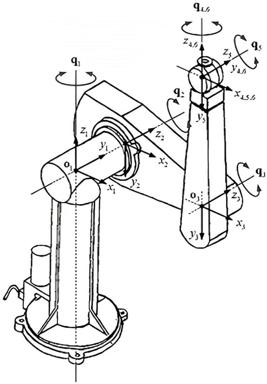
Figure 1.
PUMA560 robotic arm establishes a set of coordinate systems.
Secondly, the D-H parameter table for the master robot arm is created, as shown in Table 1, according to the method of building the system of the robot arm. The D-H parameter α and θ of the master and slave robot arms are inversely proportional to each other;

Table 1.
The D-H parameter table.
Thirdly, the transformation matrix of the robotic arm is calculated using Equation (1) and the D-H parameter table;
Finally, the forward kinematic equations are established, and the position of the end-effector relative to the reference coordinate system is calculated by connecting the coordinate systems of the six joints using Equation (2) and the aforementioned transformation matrix.
Several problems that will be faced while solving the using inverse kinematics [14] of a robotic arm are as follows:
- Multiple Solution Problem: The presence of various joint angle solutions for a given end-effector position and orientation complicates the selection of the optimal or most suitable solution, leading to ambiguity [15];
- Singular Solution Problem: Certain configurations of the robotic arm can result in singularity issues, where the position and orientation of the end-effector cannot be uniquely determined at specific joint angles [16];
- Numerical Instability Problem: Solving inverse kinematics involves numerical computations and optimization methods. Numerical stability is crucial; errors or instabilities in computation can affect the accuracy and reliability of the solution and may cause instability in the robotic arm’s movements [17];
- High Computational Complexity: Inverse kinematics solutions typically require complex mathematical calculations and algorithms. This is particularly true for high-degree-of-freedom robotic arms or complex tasks, leading to a time-consuming solution process [18].
To address the issues in trajectory planning, this paper proposes a method that combines an improved RRT algorithm with forward kinematics to plan paths for dual-arm motion after resolving collision problems.
3. Improved RRT Algorithm
The improved RRT algorithm presented in this paper incorporates a more precise collision detection method and a more efficient cost function, leading to reduced planning time and fewer steps compared to the traditional RRT algorithm [19]. Furthermore, an interpolation method is introduced to ensure smoother trajectory planning.
3.1. Dual-Arm Path Planning Based on the Improved RRT Algorithm
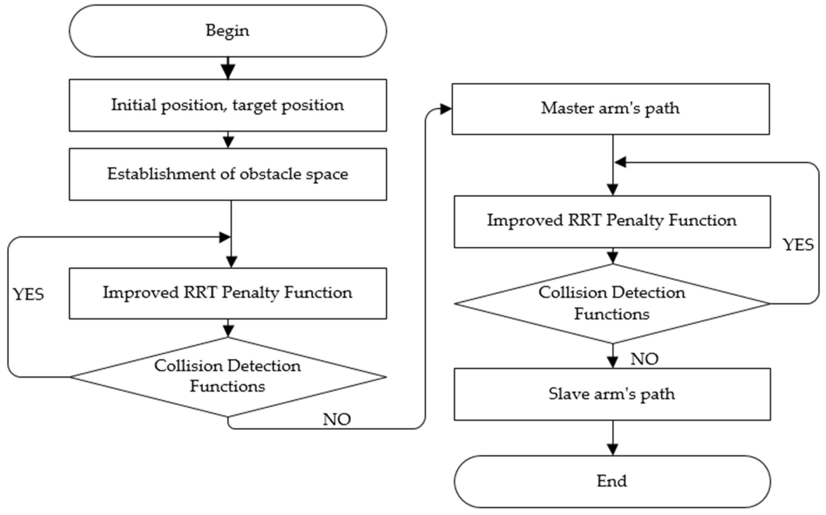
First, the initial and target positions of both the master and slave robotic arms are determined. Subsequently, one of the robotic arms is designated as the master, while the other functions as the slave. Next, create an obstacle course environment. The robot body itself is also utilized as an obstacle within this environment. Next, a feasible path for the master arm is charted amidst the obstacles using a path planning algorithm. Finally, the master arm is dynamically incorporated as an obstacle, and a viable path for the slave arm is planned accordingly. The overall algorithmic process is depicted in Figure 2, highlighting the establishment of obstacle space, the ExtendTreeRobot function, and collision detection as pivotal enhancements within the algorithm.

Figure 2.
Overall Idea Flowchart.
3.2. Obstacle Generation Function
In this paper, spheres are used as obstacles. Spherical obstacles are generated using information about their locations and radii. Using a spherical obstacle is considered an effective approach in robotic arm trajectory planning, offering several key advantages: it simplifies the model, enhances computational efficiency, facilitates extension, and provides a better approximation. This method can significantly reduce the complexity of the planning algorithm and streamline the collision detection process, thereby expediting the execution of path planning.
3.3. Improved Penalty Function for the RRT Algorithm
In path planning, the root pose node of the robotic arm acts as the starting point. An improved Rapidly Exploring Random Tree (RRT) utilizes a penalty function to expand a randomized tree structure consisting of pose nodes. This expansion includes sampling and adding leaf pose nodes. Once the target pose node is incorporated into the random tree, a path from the initial pose node to the target pose node can be established.
This paper enhances the traditional RRT penalty function by integrating a cost function and implementing a rapid convergence policy. Furthermore, innovation is introduced by adjusting the weights between distance cost and variation cost within the penalty function, as well as incorporating weights for each joint. These enhancements aim to accommodate real-world conditions, thereby enhancing the algorithm’s applicability in practical scenarios. The improved RRT penalty function proposed in this paper is formulated as follows:
In Equation (3), is the total path cost (path cost, abbreviated as C) from the pose node to the current random pose node , that has been generated by the algorithm; is the Eulerian distance cost of the end pose of the robotic arm, , in the state of the pose node to the goal pose, ; is the extended random tree currently generated by the algorithm, and a smaller Euler distance cost indicates a better current end position of the robotic arm; is the degree of change in the angle of the various joints of the robotic arm from the pose node that has already been generated to the current randomized pose node , and the smaller the degree of change, the higher the performance of the robotic arm movement smoothness; and is the weighted optimal solutions for the end pose of the robotic arm and the weighted optimal solution for the smoothness of the robotic arm motion, respectively.
In Equation (6), and are two adjacent pose nodes, is the degree of change of the angle of each joint of these two adjacent pose nodes, because in the actual working conditions, the load-bearing and wear degree of the joints of the robotic arm is not the same, and weights should be set up between the joints, to ensure that the service life of the robotic arm and the benefits are maximized, the introduction of weights , where the value is based on a set of optimal weights obtained from many experiments.
Equations (10) and (11) represent the adaptive weights. The Eulerian distance cost decreases with sampling and tends to zero continuously; three intervals are set for this distance cost, e.g., the first interval corresponds to a group of , ; the weights of the optimal solution for the smoothness of the movement of the robotic arm need to be increased when the distance cost is small and decreased when this distance cost is large, and three sets of better , are obtained in several experiments. When this distance cost is large, the weight of the optimal solution for the smoothness of the movement of the robotic arm needs to be reduced, and three sets of optimal , are obtained in many experiments; in the sampling process, the Eulerian distance cost enters into the corresponding interval, and then the size of the weights is changed adaptively.
Dual-arm robots often experience reduced search efficiency due to their large size and workspace, as well as the expansive search space of the rapidly expanding random tree function. To enhance search efficiency, we propose an improved RRT algorithm that optimizes the filtering of traversed robotic arm positions. The introduction of a cost function facilitates a gradual optimization process during search, enabling pruning of suboptimal solutions, reduction of algorithmic traversal space, and improvement of overall search efficiency. When targeting a specific position, an initial error range is defined; nodes within this range relative to the current and target positions are retained in the algorithmic traversal space, while those outside are excluded.
An example explaining this function follows:
- (1)
- Select a random joint from the 6 joints of the robotic arm, such as joint 2, and set the algorithm step size to 5°;
- (2)
- Within the interval [−90°, 90°], randomly select an angle in 5° increments. If the angle is positive, rotate 5° clockwise; if the angle is negative, rotate 5° counterclockwise. Assume a positive angle is randomly selected;
- (3)
- Rotate joint 2 clockwise by 5° from its initial angle (angle 1), designating this new position as angle 2 for the child node in the random tree, with angle 1 noted as its parent node;
- (4)
- Randomly choose another joint from the 6 joints, for example, joint 3;
- (5)
- Within the interval [−90°, 90°], randomly select an angle, such as 30°;
- (6)
- Rotate joint 3 clockwise by 5° from the angle 2 of the child node in the random tree, assigning this as angle 1;
- (7)
- Define the cost function;
- (8)
- If the cost function value for angle 2 of the random tree’s child node is minimal, then rotate joint 3 clockwise by 5° from angle 2 of the random tree’s child node, designating it as angle 3;
- (9)
- Achieve rapid convergence;
- (10)
- Utilize the Robotics Toolbox function to map angles to positions for the 6 joints;
- (11)
- Implement the collisionRobot function to prevent collisions between the master arm and obstacles;
- (12)
- Repeat the above steps until the distance between the new node and the target node is within the specified error range, terminating the loop at this point;
- (13)
- Make fine adjustments to the final end position to precisely reach the target location.
Algorithm 1 below shows the detailed flow of the function.
| Algorithm 1. ImprovedTreeRobot |
| Function1: ImprovedTreeRobot |
| , max_iterations |
| # Initialize an empty pose x and an empty node P x = None P = None # Initialize iterations to keep track of iteration counts iterations = 0 is the end position of the robot arm at the start do ) using forward kinematics ) if iterations < max_iterations do # Calculate the cost C that minimizes C ) ) ) else # Similarly, calculate the cost C , n) that minimizes C respectively ) ) ) end # If a collision is detected, generate a new random node if CollisionCheck(x) == 1 then GenerateRand() else to their respective node sets = S = P # Add iterations iterations = iterations + 1 end ) end do ) end |
3.4. Collision Detection Function
Static obstacles refer to randomly generated spherical obstacles in space. Both the master and slave arms must perform collision detection with these static obstacles during path planning to generate a collision-free trajectory. Dynamic obstacles occur when the slave arm treats the moving master arm as a dynamic obstacle while the master arm follows the planned trajectory. To balance the hardware’s computational power and the trajectory planning algorithm’s solution quality, a 100-millisecond time window is introduced into the trajectory planning process.
The master arm is treated as a dynamic obstacle in the following manner: within the first 50 milliseconds of the time window, the positions of each joint in the master arm’s trajectory, along with the mid-points between adjacent joint positions, are used as the centers of dynamic obstacle spheres. The radius of these spheres is determined by the length of the robotic arm’s rods, creating a collection of spherical obstacles for the first 50 milliseconds.
During the trajectory planning of the master arm, it is ensured that the distance between any joint position or rod midpoint and the center of a static obstacle sphere exceeds 1.2 times the radius of the static obstacle sphere. Considering the physical dimensions of the robotic arm and the factors discussed in this study, the radius of the obstacle sphere is increased by 20% to ensure collision avoidance.
The slave arm considers both static and dynamic obstacles during its trajectory planning. The master and slave arms are temporally coordinated during trajectory planning, with a 50-millisecond delay for the slave arm relative to the master arm. The slave arm uses the dynamic obstacle space generated by the master arm within the first 50 milliseconds of the time window for collision detection and completes its trajectory planning within the second 50 milliseconds, before proceeding to the next time window.
Algorithm 2 below shows the collision detection function, which gives an example of collision detection for the first rod, and the collision detection in real trajectory planning needs to cover all the rods of the robot arm.
| Algorithm 2. collisonRobot |
| Function2: collisonRobot |
| ), obstacle |
| ) |
| indicates the position of the 6 joints #Example of the first rod’s collision avoidance |
| = , = , = |
| #r is the radius of the obstacle sphere, c is the center coordinate of the obstacle sphere |
| if |||| < 1.2r and |||| < 1.2r and |||| < 1.2r |
| then during the collision detection process |
| ) = 1 |
| end |
4. Simulation Experiment
The improved RRT algorithm proposed in this study was validated experimentally using MATLAB. Table 2 presents the initial simulation parameters used for planning dual-arm trajectories under random obstacle conditions.
Table 2.
Randomized obstacle simulation experiment parameters.
In this simulation experiment, we conducted ten groups of trials, each varying in the number of obstacles randomly generated from 1 to 10. For each experimental group, we executed 200 motion planning trajectories and recorded the average planning time and success rate. The static sphere obstacles differed in number, position, and radius across groups. Obstacles were placed to avoid the initial position of the dual-arm, with a maximum radius limit to ensure sufficient movement space. Table 3 presents the statistical outcomes from these ten experimental sets.
Table 3.
Results of the improved RRT algorithm run.
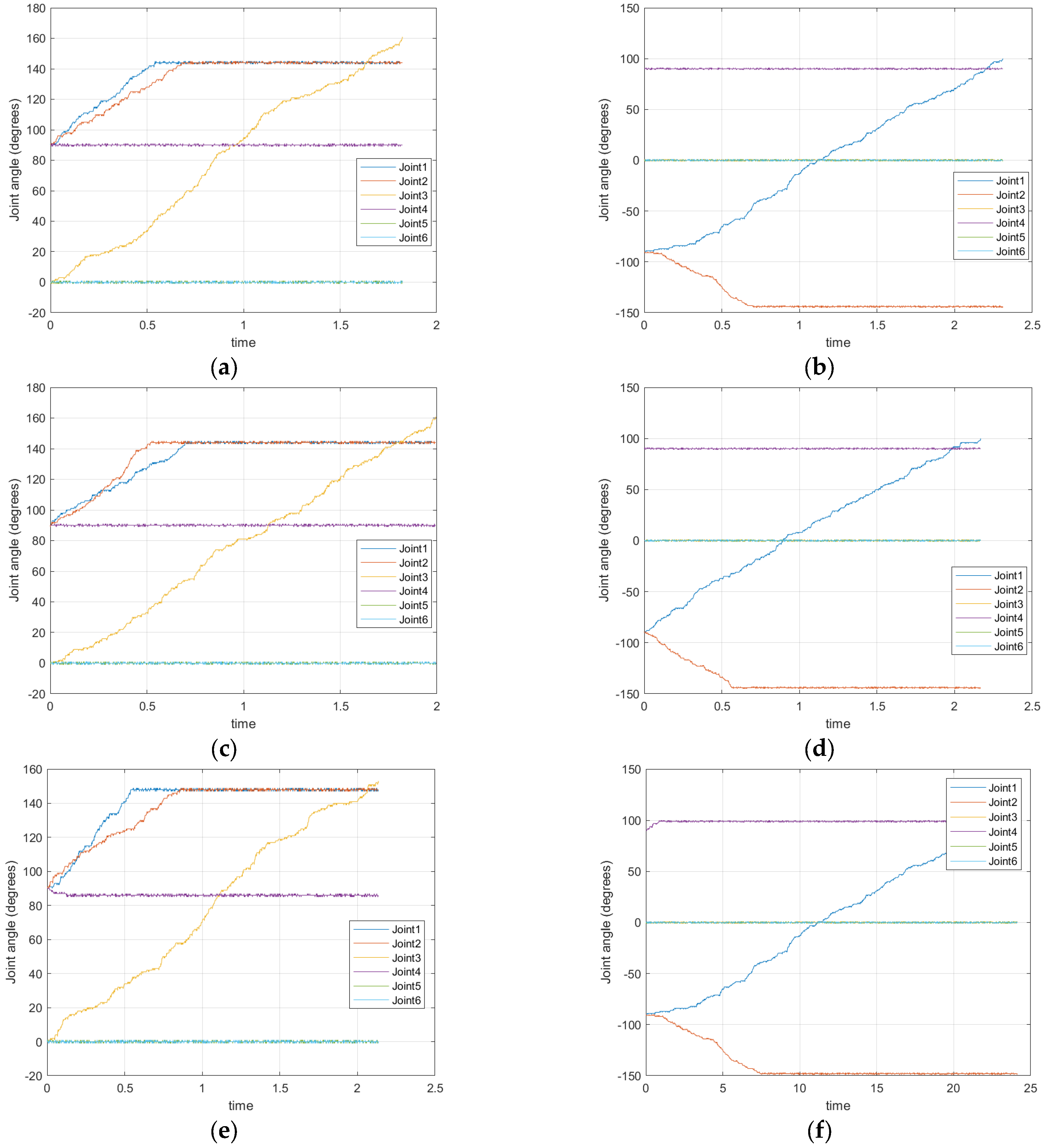
Figure 3 illustrates the trajectories of the robotic arms during the simulation experiments.
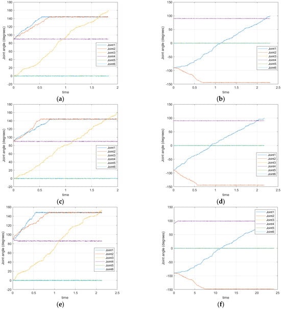
Figure 3.
Trend of the angle of the arms in the random obstacle simulation experiment. Panels (a,b) depict the trajectories of the dual–arm in a single–obstacles experiment. Panels (c,d) display the trajectory of the dual–arm movement in a five–obstacles experiment. Panels (e,f) show the trajectories of the dual–arm in a ten–obstacles experiment. The left set of three figures de–picts the trajectories of the master arm, while the right set represents those of the slave arm. Six joints in the image correspond to six colors.
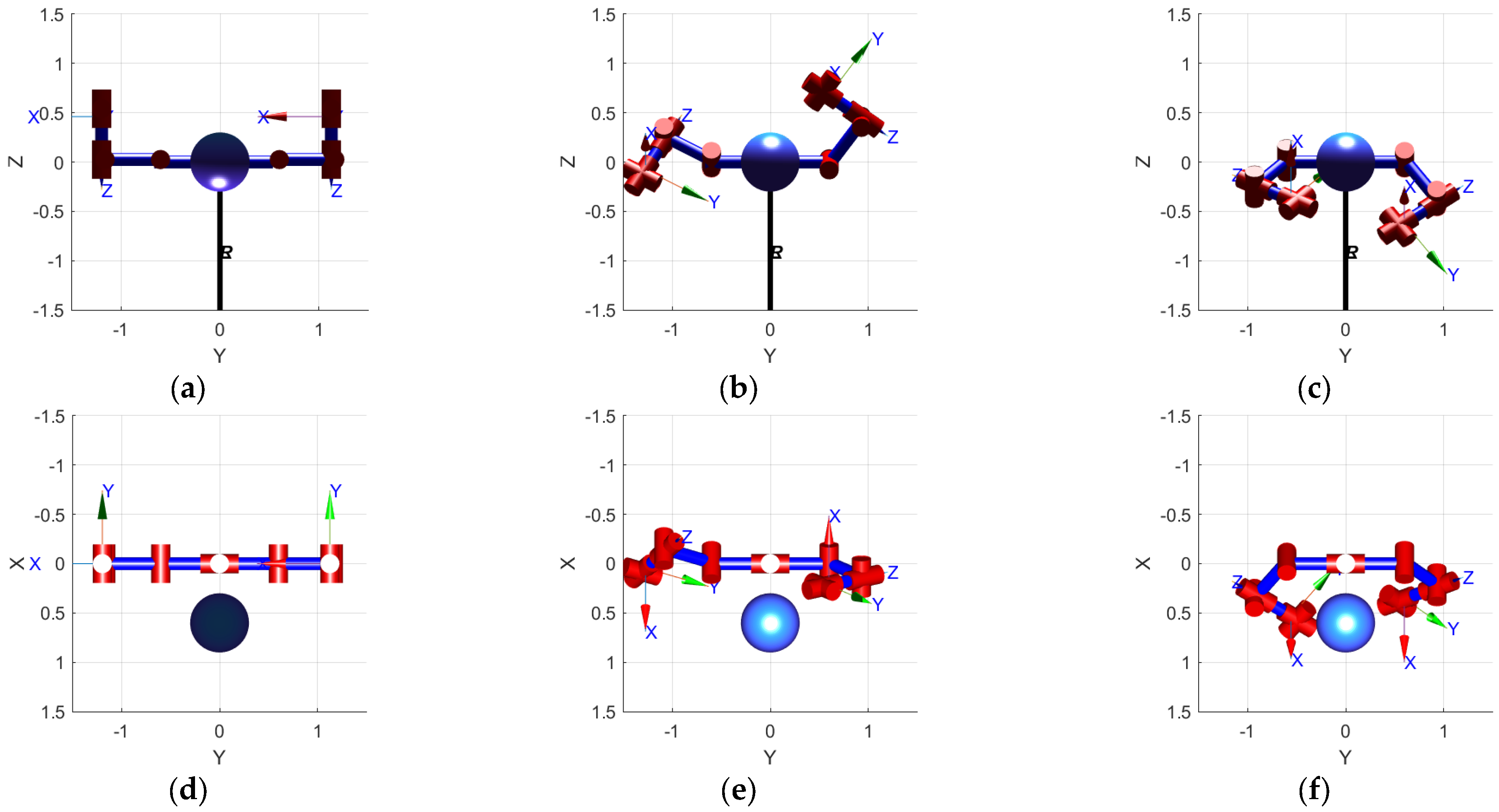
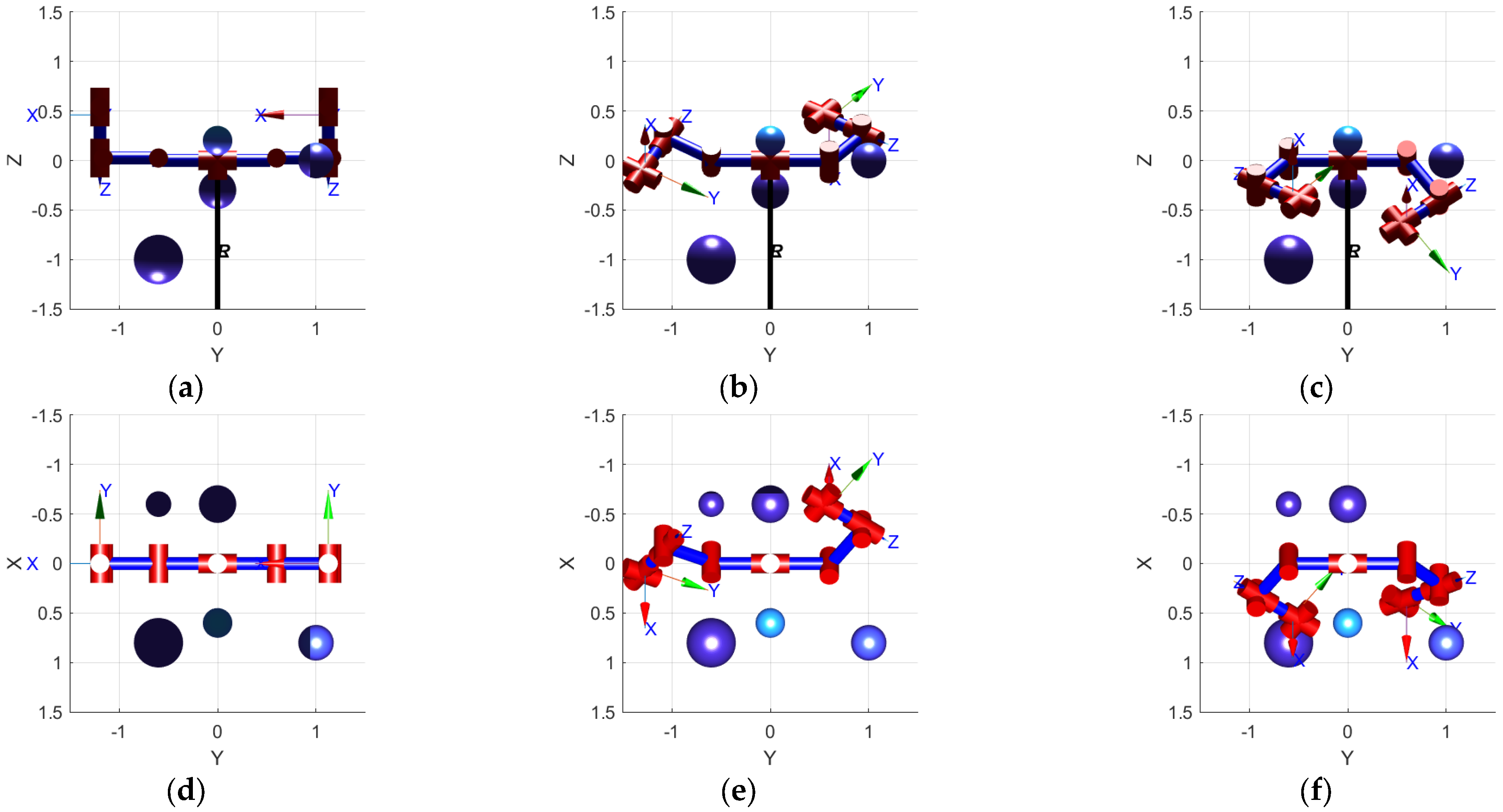
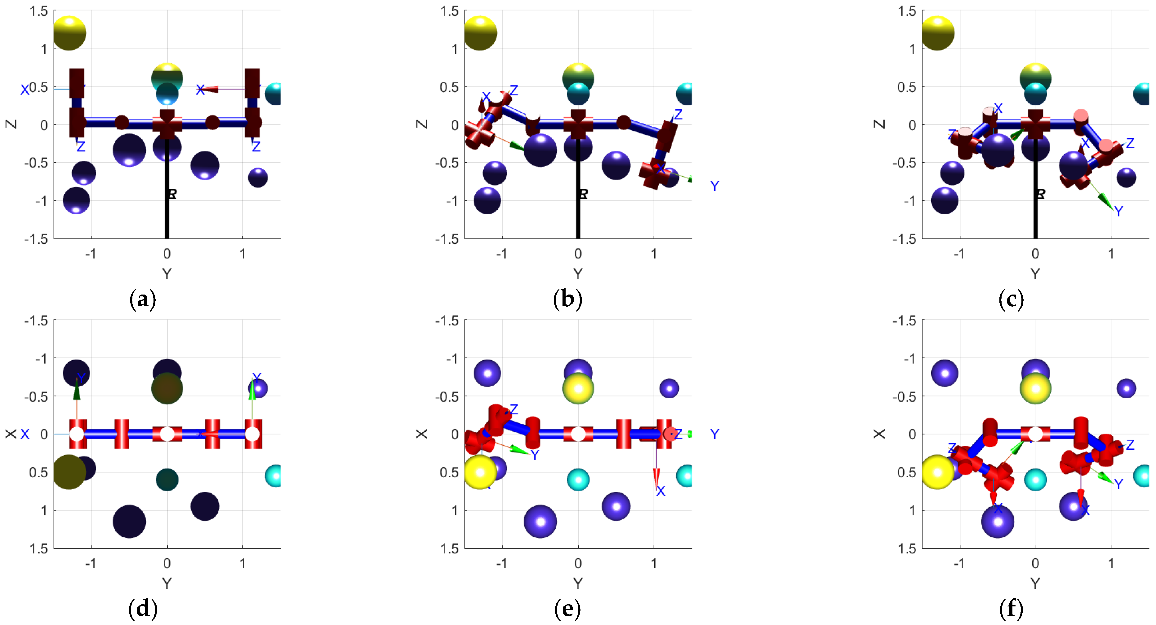
The trajectories generated by the improved RRT algorithm were simulated using the Robotics Toolbox in MATLAB. Simulation results from three randomly selected experiments are depicted in Figure 4, Figure 5 and Figure 6. These experiments demonstrate that the proposed simulation algorithm effectively generates collision-free paths for both the master arm and the slave arm. This capability enables the dual-arm to transition from their initial positions to designated target positions, confirming the feasibility and effectiveness of the improved RRT algorithm introduced in this study.
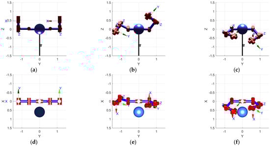
Figure 4.
One random obstacle simulation experiment. (a–c) depict the initial state main view, in–termediate state main view, and end state main view of the dual robotic arm. (d–f) depicts the initial state top view, intermediate state top view, and end state top view of the dual robotic arm.
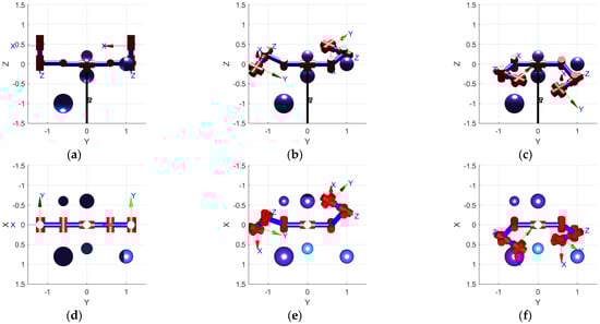
Figure 5.
Five random obstacle simulation experiments. (a–c) depict the initial state main view, in–termediate state main view, and end state main view of the dual robotic arm. (d–f) depicts the initial state top view, intermediate state top view, and end state top view of the dual robotic arm.
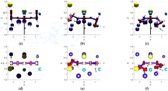
Figure 6.
Ten random obstacles simulation experiments. (a–c) depict the initial state main view, int–ermediate state main view, and end state main view of the dual robotic arm. (d–f) depicts the initial state top view, intermediate state top view, and end state top view of the dual robotic arm.
5. Discussion
The algorithm proposed in this paper achieves good results in solving the dual-arm collaborative obstacle avoidance path planning problem. By integrating an improved Rapidly Exploring Random Tree (RRT) approach, the algorithm effectively plans obstacle-free paths for both the main and slave arms. Notably, the introduction of a novel cost function with adaptive weights improves convergence speed and enhances path quality by balancing distance and variation costs. Moreover, the algorithm’s capability to handle dynamic obstacles, treating the main arm’s poses as such for the slave arm, underscores its adaptability in real-world scenarios [20]. The inclusion of interpolation functions further ensures smoother path execution, validated through rigorous MATLAB simulations. While the algorithm has yielded good results, further enhancements could be explored to address computational complexity and scalability in highly dynamic environments.
6. Conclusions
This paper presents an improved Rapidly Exploring Random Tree (RRT) algorithm designed specifically for addressing dynamic cooperative obstacle avoidance in path planning for dual-arm robots. The effectiveness of the proposed approach is thoroughly validated through experimental verification.
- The improved RRT algorithm proposed in this study exhibits outstanding experimental results in dual-arm collision avoidance trajectory planning. Extensive experiments confirm that the algorithm achieves high planning speed and success rates in handling trajectory planning amid numerous obstacles;
- To address the inherent path roughness of the improved RRT algorithm, path smoothing is achieved through interpolation and an increased number of nodes. This refinement significantly enhances the smoothness of the generated trajectories;
- To tackle challenges associated with multi-solution, singularities, and computational complexity in robot inverse kinematics, this study advocates using robot forward kinematics for trajectory planning, thereby improving computational efficiency;
- By employing a master-slave coordinated control approach, obstacle avoidance planning begins with the master arm. Subsequently, the slave arm leverages the trajectory of the master arm (left arm) for obstacle avoidance path planning;
- The effectiveness and feasibility of the algorithm are validated through numerical simulations using the Robotics Toolbox in MATLAB as part of the experimental methodology.
Author Contributions
Conceptualization, Z.D.; methodology, Z.D. and B.Z.; software, Z.D. and B.Z.; validation, B.Z., J.H. and Z.G.; formal analysis, B.Z.; investigation, B.Z.; resources, J.H. and Z.G.; data curation, Z.D. and B.Z.; writing—original draft preparation, B.Z.; writing—review and editing, Z.D.; visualization, J.H. and Z.G.; supervision, Z.D.; project administration, Z.D.; funding acquisition, Z.D. All authors have read and agreed to the published version of the manuscript.
Funding
This research received no external funding.
Data Availability Statement
The original data contributions presented in the study are included in the article, further inquiries can be directed to the corresponding authors.
Conflicts of Interest
The authors declare no conflicts of interest.
References
- Anh, T.L.; Phuc, H.Q. Adaptive fractional-order integral fast terminal sliding mode and fault-tolerant control of dual-arm robots. Robotica 2024, 42, 1476–1499. [Google Scholar]
- Ge, J.; Kam, M.; Opfermann, J.D.; Saeidi, H.; Leonard, S.; Mady, L.J.; Schnermann, M.J.; Krieger, A. Autonomous System for Tumor Resection (ASTR)—Dual-Arm Robotic Midline Partial Glossectomy. IEEE Robot. Autom. Lett. 2024, 9, 1166–1173. [Google Scholar] [CrossRef] [PubMed]
- Long, H.; Li, G.; Zhou, F.; Chen, T. Cooperative Dynamic Motion Planning for Dual Manipulator Arms Based on RRT*Smart-AD Algorithm. Sensors 2023, 23, 7759. [Google Scholar] [CrossRef] [PubMed]
- Marco, R.; Matthieu, J.; Marco, S.; Alessandra, A.; Cesare, M. Collision-free and smooth motion planning of dual-arm Cartesian robot based on B-spline representation. Robot. Auton. Syst. 2023, 170, 104534. [Google Scholar]
- Petit, L.; Desbiens, A.L. RRT-Rope: A deterministic shortening approach for fast near-optimal path planning in large-scale uncluttered 3D environments. In Proceedings of the 2021 IEEE International Conference on Systems, Man, and Cybernetics (SMC), Melbourne, Australia, 17–20 October 2021; pp. 1111–1118. [Google Scholar]
- Xanthidis, M.; Esposito, J.M.; Rekleitis, I.; O’Kane, J.M. Motion planning by sampling in subspaces of progressively increasing dimension. J. Intell. Robot. Syst. 2020, 100, 777–789. [Google Scholar] [CrossRef]
- Gammell, J.D.; Srinivasa, S.S.; Barfoot, T.D. Informed RRT*: Optimal sampling-based path planning focused via direct sampling of an admissible ellipsoidal heuristic. In Proceedings of the 2014 IEEE/RSJ International Conference on Intelligent Robots and Systems, Chicago, IL, USA, 14–18 September 2014; pp. 2997–3004. [Google Scholar]
- Brunner, M.; Brüggemann, B.; Schulz, D. Hierarchical rough terrain motion planning using an optimal sampling-based method. In Proceedings of the 2013 IEEE International Conference on Robotics and Automation, Karlsruhe, Germany, 6–10 May 2013; pp. 5539–5544. [Google Scholar]
- Ranganathan, A.; Koenig, S. PDRRTs: Integrating graph-based and cell-based planning. In Proceedings of the 2004 IEEE/RSJ International Conference on Intelligent Robots and Systems (IROS) (IEEE Cat. No. 04CH37566), Sendai, Japan, 28 September–2 October 2004; pp. 2799–2806. [Google Scholar]
- Azita, A.; Babak, A.; Mojtaba, V. Self-Tuning Fuzzy Task Space Controller for Puma 560 Robot. J. Electr. Eng. Technol. 2020, 16, 579–589. [Google Scholar]
- Lavín-Delgado, J.E.; Solís-Pérez, J.E.; Gómez-Aguilar, J.F.; Escobar-Jiménez, R.F. Trajectory tracking control based on non-singular fractional derivatives for the PUMA 560 robot arm. Multibody Syst. Dyn. 2020, 50, 259–303. [Google Scholar] [CrossRef]
- Lin, W.; Yuefa, F.; Dan, Z.; Yi, Y. Kinematics and optimization of a novel 4-DOF two-limb gripper mechanism. Robotica 2023, 41, 3649–3671. [Google Scholar]
- Zhu, C.; Zhao, Z. Research on Influence of Joint Clearance on Precision of 3-TPT Parallel Robot. Mech. Sci. 2019, 10, 287–298. [Google Scholar] [CrossRef]
- Abbes, M.; Poisson, G. Geometric Approach for Inverse Kinematics of the FANUC CRX Collaborative Robot. Robotics 2024, 13, 91. [Google Scholar] [CrossRef]
- Jennifer, D.; Thorsteinn, R.; Bo, S.; Mattias, O. Deterministic annealing with Potts neurons for multi-robot routing. Intell. Serv. Robot. 2022, 15, 321–334. [Google Scholar]
- Polyakova, A.P.; Svetov, I.E. A numerical solution of the dynamic vector tomography problem using the truncated singular value decomposition method. J. Inverse Ill-Posed Probl. 2024, 32, 145–160. [Google Scholar] [CrossRef]
- Pan, V.Y.; Soleymani, F.; Zhao, L. An efficient computation of generalized inverse of a matrix. Appl. Math. Comput. 2018, 316, 89–101. [Google Scholar] [CrossRef]
- Guichao, L.; Peichen, H.; Minglong, W.; Yao, X.; Rihong, Z.; Lixue, Z. An Inverse Kinematics Solution for a Series-Parallel Hybrid Banana-Harvesting Robot Based on Deep Reinforcement Learning. Agronomy 2022, 12, 2157. [Google Scholar] [CrossRef]
- Cui, X.; Wang, C.; Xiong, Y.; Mei, L.; Wu, S. More Quickly-RRT*: Improved Quick Rapidly-exploring Random Tree Star algorithm based on optimized sampling point with better initial solution and convergence rate. Eng. Appl. Artif. Intell. 2024, 133, 108246. [Google Scholar] [CrossRef]
- Merckaert, K.; Convens, B.; Nicotra, M.M.; Vanderborght, B. Real-time constraint-based planning and control of robotic manipulators for safe human–robot collaboration. Robot. Comput.-Integr. Manuf. 2024, 87, 102711. [Google Scholar]

Disclaimer/Publisher’s Note: The statements, opinions and data contained in all publications are solely those of the individual author(s) and contributor(s) and not of MDPI and/or the editor(s). MDPI and/or the editor(s) disclaim responsibility for any injury to people or property resulting from any ideas, methods, instructions or products referred to in the content. |
© 2024 by the authors. Licensee MDPI, Basel, Switzerland. This article is an open access article distributed under the terms and conditions of the Creative Commons Attribution (CC BY) license (https://creativecommons.org/licenses/by/4.0/).