Article

A Prediction Model of Two-Sided Unbalance in the Multi-Stage Assembled Rotor of an Aero Engine

1
College of Mechanical Engineering, Tianjin University of Technology and Education, Tianjin 300222, China
2
School of Aviation and Aerospace, Tianjin Sino-German University of Applied Sciences, Tianjin 300350, China
3
College of Electronic Information and Automation, Tianjin University of Science and Technology, Tianjin 300222, China
*
Author to whom correspondence should be addressed.
Machines 2024, 12(8), 503; https://doi.org/10.3390/machines12080503
Submission received: 14 June 2024 / Revised: 21 July 2024 / Accepted: 22 July 2024 / Published: 24 July 2024
(This article belongs to the Special Issue New Advances in Rotating Machinery)

Abstract

:
In rotating machinery with a multi-stage assembled rotor, such as is found in aero engines, any unbalance present will undergo unknown changes at each stage when rotating the assembly phases of the rotor. Repeated disassembly and adjustments are often required to meet the rotor’s residual unbalance specifications. Therefore, developing a prediction model of this two-sided unbalance for a multi-stage assembled rotor is crucial for improving the first-time assembly pass rate and assembly efficiency. In this paper, we propose a prediction model of the two-sided unbalance seen in the multi-stage assembled rotor of an aero engine. Firstly, a method was proposed to unify the mass feature parameters of each stage’s rotor into a geometric measurement coordinate system, achieving the synchronous transmission of geometric and mass feature parameters during the assembly process of the multi-stage rotor. Building upon this, a linear parameter equation of the actual rotation axis of the multi-stage rotor was established. Based on this axis, the mass eccentricity errors of the rotor were calculated at each stage, further enabling the accurate prediction of two-sided unbalance and its action phase in a multi-stage rotor. The experimental results indicate that the maximum prediction errors of the two-sided unbalance and its action phase for a four-stage rotor are 9.6% and 2.5%, respectively, when using this model, which is a reduction of 53.0% and 38.1% compared to the existing model.

1. Introduction

Unbalance is an important factor causing vibration faults in rotating machinery such as aero engines and gas turbines [1,2]. Aero engines and gas turbines are assembled by stacking multiple stages of rotors; thus, the dimensional and positional errors of single-stage rotors accumulate during the assembly process, causing the rotors to deviate from their ideal assembly positions, resulting in mass eccentric errors in the multi-stage assembled rotor relative to its actual rotation axis.
The traditional method for removing unbalance is to first place the unbalanced rotor on the support pendulum of a dynamic balancing machine and then measure the unbalance and its action phase in two predefined balancing planes when under the working rotational speed of the unbalanced rotor. Finally, balance weights are applied on the two predefined balancing planes, and the process is repeated until the residual unbalance meets the specified criteria [3,4]. However, for multi-stage assembled rotors, in addition to the unbalance criteria, certain concentricity criteria must also be satisfied [5,6,7]. The traditional method for adjusting the concentricity of a multi-stage assembled rotor is to rotate each stage of the rotor to its appropriate assembly phase, aiming to position the center lines of the rotor as close to a straight line as possible. This is also known as the “straight-build” method, which was proposed by Hussain et al. [8,9,10]. However, when rotating the assembly phases of the rotors at each stage, the unbalance of the multi-stage assembled rotor also changes. Measuring and adjusting the dual criteria require separate equipment and often necessitate repeated disassembly and adjustment to simultaneously meet both criteria. Therefore, developing a prediction model of the unbalance for a multi-stage assembled rotor is particularly important for improving the first-time assembly qualification rate and assembly efficiency.
To accurately predict the unbalance of a multi-stage assembled rotor, an accurate assembly error transfer model is required. Yang et al. [11,12,13,14] extended the two-dimensional assembly error transfer model used in the “straight-build” method to three dimensions and then combined it with tolerance analysis theory. In this model, it is assumed that the key dimensions of the rotors at each stage are normally distributed within a given tolerance band. By employing the Monte Carlo method, the range of the various geometric eccentricity errors of the rotors at each stage can be accurately predicted after assembly. Based on the dovetail assembly method of multi-stage rotors in aero engines, Shan et al. [15] established a dimensional chain model of multi-stage rotors that includes both dimensional errors and positional errors. The Pearson distribution family method was introduced to investigate the distribution characteristics of assembly errors under normal and non-normal distribution scenarios for the input parameters. Meng et al. [16] further extended the aforementioned two-dimensional chain model to three dimensions and then established a functional relationship between the concentricity of the rotor at its final stage and the assembly phase of rotors at each stage. The Monte Carlo method was employed to simulate and predict the concentricity qualification rate of a multi-stage rotor. Zhang et al. [17] established an assembly deviation analysis model of micro gas turbine core engines, based on design tolerance. The key factors of the occurrence of assembly deviation and the causes of these errors were analyzed through Monte Carlo operations, which solved the assembly interference and collision caused by unreasonable design through optimization.
The aforementioned studies fundamentally concern tolerance analyses, which involve the application of statistical methods to evaluate the geometric eccentricity error of a multi-stage assembled rotor at all assembly phases, given the key dimensional tolerance bands of the rotors at each stage. Such methods can provide some guidance for tolerance allocation in the design phase. However, the problem with the above methods is that they have not established a function that takes the assembly phases of rotors at each stage as the control variable and the assembly concentricity as the optimization objective, resulting in their inability to provide the optimal assembly phase for rotors at each stage.
Wang et al. [18] constructed an assembly error transfer model of a multi-stage rotor based on the positioning and orienting errors of its rotors at each stage. By traversing all possible assembly phases of each rotor, the coaxiality of each phase sequence was calculated; achieving the minimum coaxiality was considered the optimal assembly phase sequence. Sun et al. [19] combined the error transfer model proposed by Hussain et al. [10] with the coaxiality objective function for multi-stage rotors developed by Wang et al. [18]. They achieved an accuracy of 80% in predicting the assembly error of multi-stage rotors and proposed a correction method for the assembly phases of an aero engine based on minimizing the geometric eccentricity error.
Mu et al. [20] proposed an error model construction method considering manufacturing error and assembly deformation. The prediction results based on the proposed model are closer to actual conditions than those produced by the existing assembly precision prediction models. Liu et al. [21] built a finite element model to obtain the deformation of the bolted flange joints by simulating the assembly process of an aero engine rotor. The deformation of the flange was involved in the stack-build assembly model as an error matrix. The results showed that bolted flange joints have a significant effect on concentricity, especially regarding the complex geometry at the flange interface. Shi et al. [22] proposed a novel error propagation model that comprehensively considers real surface morphology and non-uniform contact deformation. A specific type of aero engine rotor simulator was used as the object of this study, which showed a 10.6% deviation in prediction accuracy between the classical model and the novel model.
However, in the process of optimizing the assembly of multi-stage rotors, the unbalance caused by mass eccentricity errors should also be taken into account. Zhang et al. [23] proposed a discrete improved Harris Hawk optimization algorithm to optimize the unbalance of an engine rotor assembly. However, this method does not take into account the influence of the geometric assembly errors of rotors at each stage on the unbalance of the multi-stage assembled rotor, and the optimization model is essentially a two-dimensional computational model. Zhang et al. [24] proposed a Pareto-optimal scheme combining multi-objective optimization algorithms for the stacked assembly of multi-stage rotors. However, this model was not based on the actual rotation axis of the multi-stage rotor, and the target parameters were not unified within the same coordinate system.
Liu et al. [25] proposed an assembly method for a multi-stage rotor, with the unbalance measure as the optimization objective. This method applies the assembly error transfer model from Reference [18] to the transfer of the mass eccentricity errors of rotors at each stage. However, the barycenter coordinates that are described are not obtained through actual measurement, but rather through estimation using a predetermined conversion coefficient. To address this issue, Sun et al. [26,27] used a vertical dynamic balancing machine to measure the two-sided unbalance of a multi-stage rotor and further converted it into a single-sided unbalance. The results showed that the average prediction error of this model for the mass eccentricity error was 14.38%. However, in this study, the formula used to convert the two-sided unbalance measured by the balancing machine into a single-sided unbalance had a flaw, as it did not consider the axial position of the two balancing planes. Additionally, this study only verified the prediction accuracy of the magnitude of the unbalance and did not validate the prediction accuracy of the action phase of the unbalance.
The existing research commonly adopts the geometric eccentricity error transfer model of a multi-stage rotor to predict its unbalance. However, this approach has its limitations. Firstly, the initial unbalance of a single-stage rotor should be measured relative to its actual rotation axis, i.e., the tested rotor should be placed on the supporting circular centerline of the swing frame on both sides of the dynamic balancing machine, and, secondly, each rotor has a different actual rotation axis. The measured unbalance should be converted to the measurement coordinate system used for the rotors’ geometric parameters at each stage before being introduced into the assembly model for error transmission. Secondly, the solution for the two-sided unbalance of a multi-stage rotor should also be based on its own actual rotation axis for calculation reference.
Targeting the above problems, a prediction model of two-sided unbalance in the multi-stage assembled rotor of an aero engine is proposed in this study. In Section 2.1 and Section 2.2, measurement definitions of the geometric and mass feature parameters of a single-stage rotor are provided, as are transfer formulas for converting the mass feature parameters of a single-stage rotor to the geometric measurement coordinate system. Section 2.3 implements the synchronous transfer of dual parameters within the stacking assembly process of multi-stage rotors and verifies the accuracy of the coordinate transfer using three-dimensional modeling software. Section 2.4 establishes the linear equation of the actual rotation axis of the multi-stage assembled rotor and calculates its two-sided unbalance based on its actual rotation axis. In Section 3, the calculated results of the two-sided unbalance and its action phase in a multi-stage rotor are compared between the assembly error transfer model proposed in this study and the existing model [18,19,25,26,27]. Finally, in Section 4, the accuracy of the prediction model of two-sided unbalance is validated through experiments.

2. Methods

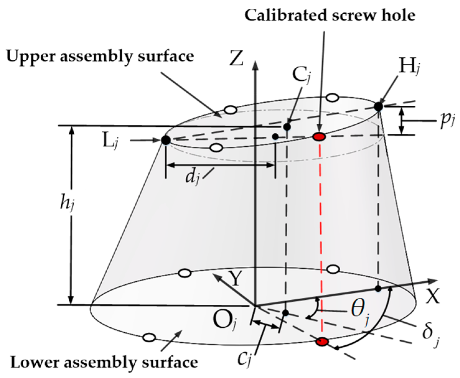
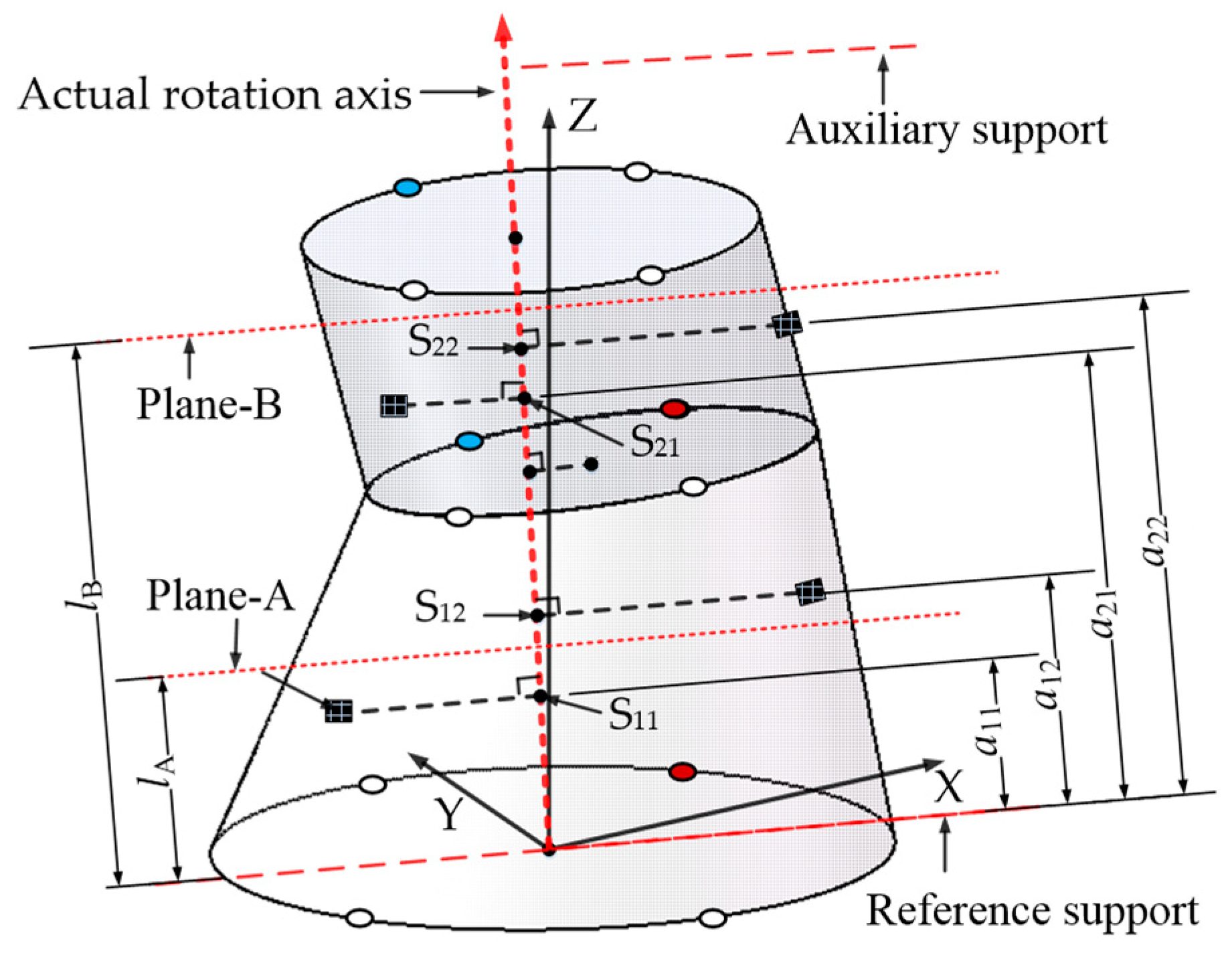
2.1. Measurement Definition of the Geometric Feature Parameters of a Single-Stage Rotor

Figure 1 displays the geometric feature parameters of a single-stage rotor, as measured using a coordinate measuring machine. The lower assembly surface of the jth-stage rotor is defined as the XY plane of the measurement coordinate system, with the Z-axis passing through the center of the front edge (Oj) and perpendicular to the lower assembly surface, and with Oj as the coordinate origin. The line connecting the highest point Hj and the lowest point Lj of the upper assembly surface is projected onto the lower assembly surface and can be defined as the X-axis. δj is the sampling angle between the center of the calibrated screw hole and Hj. hj is the vertical distance between the upper and lower assembly surfaces, and pj is the parallelism error of the upper and lower assembly surfaces. Cj and θj are, respectively, the eccentric distance and eccentric angle of the centroid of the upper assembly surface, the coordinate vector of which can be expressed as Cj = [cjcos(θj), cjsin(θj), hj]. dj is the radius of the upper assembly surface.

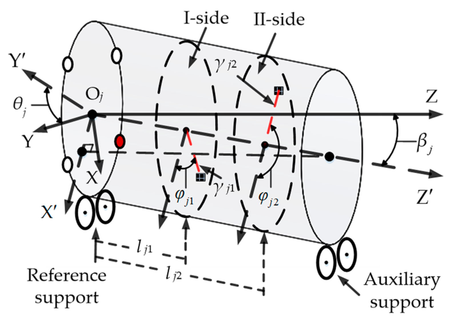
2.2. Measurement Definition for the Mass Feature Parameters of a Single-Stage Rotor

The mass feature parameters of a single-stage rotor are measured using a dynamic balancing machine, including the two-sided unbalance, its action phase, and the action radius of the unbalanced mass point, as shown in Figure 2. ϕjk and γjk are the action phase and action radius of the kth unbalanced mass point of the jth stage rotor, respectively. ljk is the distance between the kth unbalanced mass point of the jth stage rotor and the reference support. In the first step, the rotor to be measured is placed on the two-side support of the dynamic balancing machine, with the upper and lower assembly surfaces of the geometric measurement coordinate system OjXYZ placed on the left and right roller supports. In the second step, the eccentric direction (OjY′) of the center Oj of the lower assembly surface of the jth stage rotor is defined as the zero phase. In the third step, the phase in which the calibrated screw hole is located is aligned with the phase sensor. In the fourth step, the rotor to be measured is rotated by δjθj degrees. In the fifth step, retroreflective stickers are attached at the corresponding positions of the phase sensor. Upon completion of the above steps, the dynamic balancing machine can begin its measurement. The OjZ′-axis represents the measurement datum of the mass feature parameters of the jth stage rotor, which is the actual rotation axis. The coordinates of unbalanced mass points are measured relative to the coordinate system OjX′Y′Z′ and need to be further unified into the geometric measurement coordinate system OjXYZ to ensure the synchronous transmission of the geometric and mass feature parameters to the assembly model. The coordinate vector of an unbalanced mass point (Ijk) can be expressed by Equation (1). Using the coordinate conversion performed with Equation (2), Ijk is first rotated θj around the Z-axis and then rotated βj (βj = arctan(cj/hj)) around the OjY-axis. Finally, Ijk is converted into a coordinate vector Ejk relative to the coordinate system OjXYZ.
I j k = γ j k cos φ j k γ j k sin φ j k l j k j , k N , k 2 ,
E j k = I j k cos θ j sin θ j 0 sin θ j cos θ j 0 0 0 1 cos β j 0 sin β j 0 1 0 sin β j 0 cos β j .

2.3. Coordinate Transfer of Multi-Stage Assembled Rotors

Figure 3 shows the assembly calculation process of a two-stage rotor. The first step is to align the calibrated screw hole of Rotor-b with that of Rotor-a. We define the assembly phase of Rotor-b as being in its zero position, and Rotor-a is fixed by default. The second step is to rotate Rotor-b around the Z-axis at the distribution angle of the assembly screw holes and to select the appropriate assembly phase. This is necessary in order to select the assembly phase that minimizes the assembly indicators of the two-stage rotor. The third step is to rotate Rotor-b around the Y-axis so that its lower assembly surface is parallel to the upper assembly surface of Rotor-a. The fourth step is to translate the lower assembly surface of Rotor-b to the upper assembly surface of Rotor-a so that the centroid of their lips coincides. The assembly process of the j-stage rotor can be seen as the reverse assembly process of (j − 1) two-stage rotors, and the coordinate vector Xj of any point in the jth stage rotor during the assembly process can be expressed by Equation (3):
X j = X j j : 1 : 2 T z j T y j 1 + X j 1 ,
where Xj refers to the coordinate vector of Xj after its assembly transformation. Tzj and Tyj are the coordinate rotation matrixes of the jth stage rotor around the Z-axis and Y-axis, respectively (Equations (4) and (5)):
T z j = cos θ z j + δ j δ j - 1 sin θ z j + δ j δ j - 1 0 sin θ z j + δ j δ j - 1 cos θ z j + δ j δ j - 1 0 0 0 1 ,
where δjδj1 refer to the true phase difference between adjacent single-stage rotors. θzj is the optional assembly phase for the jth stage rotor relative to the (j − 1)th stage rotor. δj represents the angle between the calibrated screw hole of the jth stage rotor and the X-axis. When the calibrated screw holes of adjacent rotors are aligned, the phase difference between the jth and the (j − 1)th stage rotor becomes δjδj−1. When the jth stage rotor selects any assembly phase θzj, the phase difference between the two-stage rotors is θzj + (δjδj−1).
T y j = cos arctan p j 2 d j 0 sin arctan p j 2 d j 0 1 0 sin arctan p j 2 d j 0 cos arctan p j 2 d j .
We use a three-stage simulated rotor with the same geometric feature parameters as in Reference [17], combined with the coordinate measurement function found in the three-dimensional modeling software SOLIDWORKS 2015, to verify the accuracy of Equation (3) in calculating the transfer of centroid coordinates. As shown in Table 1, the geometric feature parameters of each stage’s rotor are identical. SOLIDWORKS is used to reconstruct the rotor model, assuming that each stage’s rotor is a rigid body with uniform density distribution. The measured initial barycenter coordinate vector of each stage’s rotor is [0.003 626, 0.000 117, 34.999 160] mm. There are currently two assembly states set. The first is the default assembly state, which means that the assembly phase of each stage’s rotor is 0°. The second state is one in which the assembly phase sequence of the three-stage simulated rotor is {θz1 = 0°, θz2 = 30°, θz3 = 60°}. By importing the initial barycenter coordinates and geometric feature parameters of each stage’s rotor into the coordinate transfer in Equation (3), the barycenter coordinates of the two assembly states can be obtained (Table 2). Comparing their coordinate measurement results in SOLIDWORKS (Figure 4), it can be seen that the calculation results from Equation (3) are almost identical to the measurement results achieved with SOLIDWORKS. Because the initial barycenter coordinates imported into Equation (3) are retained to the sixth digit after the decimal point, we can see that there is only a slight difference between the two results in the sixth digit after the decimal point.

2.4. Mass Eccentricity Cumulative Errors of a Multi-Stage Rotor, Based on Its Actual Rotation Axis

The manufacturing errors of each stage’s rotor are gradually transmitted through the front edges to form cumulative errors in the assembly process of a multi-stage rotor, which can lead to the actual spatial position of each stage’s rotor deviating from its ideal assembly position and the actual rotation axis of the whole assembly deviating from its geometric reference axis. Therefore, the geometric and mass eccentricity errors of each stage’s rotor should be recalculated relative to the actual rotation axis based on its centroid coordinates after its assembly transformation; the actual rotation axis will also change with the change in the assembly phase of each stage’s rotor. The geometric and mass eccentricity errors of a two-stage rotor at a particular assembly phase are presented in Figure 5, and its actual rotation axis is the line connecting the center of the supporting joints of the head and tail rotors. The coordinate vector of the front-edge center of the jth stage rotor is Cj = [Cjx, Cjy, Cjz], and the kth unbalanced mass point of the jth stage rotor is Ejk = [Ejkx, Ejky, Ejkz]. By importing Cj and Ejk into Equation (3), the coordinate vectors after assembly are Cj′ = [Cjx′, Cjy′, Cjz′] and Ejk′ = [Ejkx′, Ejky′, Ejkz′], respectively. The linear parameter equation of the actual rotation axis can be expressed as:
x C j x = y C j y = z C j z = λ .
The normal plane equation passing through the kth unbalanced mass point of the jth stage rotor and perpendicular to the rotation axis is:
C j x x E j k x + C j y y E j k y + C j z z E j k z = 0 .
The parameter λ of Linear Equation (6) can be obtained by combining Equations (6) and (7) as follows:
λ = C j x E j k x + C j y E j k y + C j z E j k z C j x 2 + C j y 2 + C j z 2 .
Substituting λ into Equation (6), the coordinate of the intersection point Sjk between the rotation axis and the normal plane can be obtained as follows:
S j k x = C j x 2 E j k x + C j x C j y E j k y + C j x C j z E j k z C j x 2 + C j y 2 + C j z 2 S j k y = C j x C j y E j k x + C j y 2 E j k y + C j y C j z E j k z C j x 2 + C j y 2 + C j z 2 S j k z = C j x C j z E j k x + C j y C j z E j k y + C j z 2 E j k z C j x 2 + C j y 2 + C j z 2 .
The action vector ejk of the kth unbalanced mass point of the jth stage rotor can be expressed as:
e j k = E j k x S j k x , E j k y S j k y , E j k z S j k z .

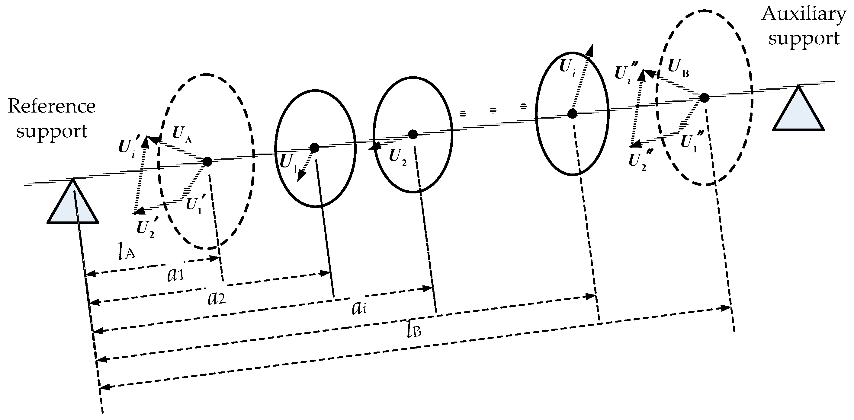
2.5. Decomposition Principle of the Two-Sided Unbalance of a Multi-Stage Rotor

Figure 6 shows a schematic diagram of the decomposition of the two-sided unbalance in a rotor dynamic balance test. Assuming that there are i unbalance vectors Ui on i planes perpendicular to the rotation axis, two planes with distances lA and lB from the reference supports are selected as the correcting planes. According to the principle of torque balance, Ui is decomposed into two sub-vectors Ui′ and Ui″ on Plane A and Plane B, and the unbalanced vectors UA and UB on Plane A and Plane B are the composite vectors of Ui′ and Ui″, respectively.
U A = i = 1 n l B a i l B l A U i U B = i = 1 n a i l A l B l A U i ,
Here, ai refers to the distance between the ith unbalanced vector and the reference support.
Figure 7 shows a schematic diagram of the decomposition of the two-sided unbalance of a two-stage rotor. When extended to a multi-stage rotor, the distance between the kth unbalanced mass point of the jth stage rotor and the reference support can be expressed as:
a j k = S j k x 2 + S j k y 2 + S j k z 2 .
If the vector direction of the first unbalanced mass point of the first-stage rotor is in the X-direction, the angle between the vector direction and the other unbalanced mass point can be expressed as:
θ j k 1 = arccos e 11 · e j k e 11 e j k .
According to Equation (11), the two-sided unbalance of each stage’s rotor can be decomposed into the unbalance of a multi-stage rotor on Plane A as follows:
U A x = j = 1 n l B a j 1 l B l A u j 1 e j 1 cos θ j 1 1 + l B a j 2 l B l A u j 2 e j 2 cos θ j 2 1 U A y = j = 1 n l B a j 1 l B l A u j 1 e j 1 sin θ j 1 1 + l B a j 2 l B l A u j 2 e j 2 sin θ j 2 1 ,
where ujk is the kth unbalanced mass of the jth stage rotor and ujkejk is the kth unbalance of the jth stage rotor (mass–radius product). Similarly, the two-sided unbalance of each stage’s rotor can be decomposed into the unbalance of a multi-stage rotor on Plane B as follows:
U B x = j = 1 n a j 1 l A l B l A u j 1 e j 1 cos θ j 1 1 + a j 2 l A l B l A u j 2 e j 2 cos θ j 2 1 U B y = j = 1 n a j 1 l A l B l A u j 1 e j 1 sin θ j 1 1 + a j 2 l A l B l A u j 2 e j 2 sin θ j 2 1 .
The two-sided unbalance of a multi-stage rotor can be determined using Equation (16), and its action phase can be expressed through Equation (17):
U A = U A x 2 + U A y 2 U B = U B x 2 + U B y 2 ,
ζ A = arctan U A y U A x + φ 11 ζ B = arctan U B y U B x + φ 11

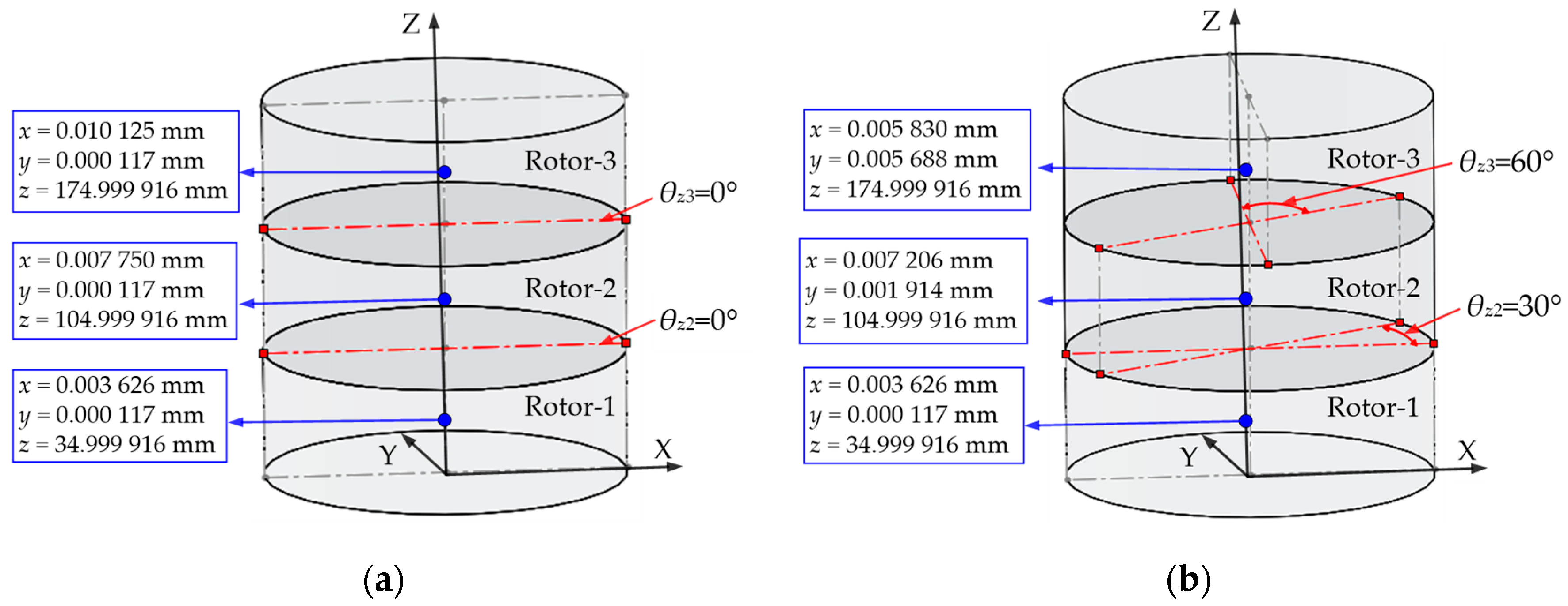
3. Simulation Analysis of the Two-Sided Unbalance of a Multi-Stage Rotor

Figure 8 shows a simulated rotor that reduces the real four-stage high-pressure rotor of a certain aero engine by 10 times. The rotor system is assembled step-by-step from a front axle, a compressor, a high-pressure turbine, and a rear axle, defined as Rotor-1 to Rotor-4, respectively. The high-pressure turbine is composed of a drum and a turbine disk, which are pre-assembled and held together with screws. The assembly surface of the lower lip of each stage’s rotor is defined as the measurement reference for the geometric feature parameters, and the assembly surfaces of the upper and lower lips of each stage’s rotor are defined as the positions of the reference support and the auxiliary support for measuring mass feature parameters. The geometric and mass feature parameters of each stage’s rotor are shown in Table 3 and Table 4. The front axle is fixed by default, with an assembly phase θz1 of 0°, and is connected to the compressor using 12 evenly distributed screws. The optional assembly phases θz2 after aligning the assembly screw holes of the compressor and the front axle are 0°, 30°, 60°, 90°, 120°, 150°, and 180°, respectively. The high-pressure turbine and the compressor are connected by 24 evenly distributed screws, which allows for optional assembly phases θz3; after aligning, the assembly screw holes of the high-pressure turbine and the compressor are at 0°, 15°, 30°, 45°, 60°, 75°, 90°, 105°, 120°, 135°, 150°, 165°, and 180°, respectively. The rear axle is connected to the high-pressure turbine using 12 evenly distributed screws—that is, the optional assembly phase θz4 can be selected to be the same as θz2 after the assembly screw holes of the rear axle and high-pressure turbine are aligned. The distances lA and lB between the two balanced planes A and B and the reference support of the four-stage rotor are defined as 71 mm and 315 mm, respectively.
Figure 9 shows the point cloud diagram of the unbalance UA and its action phase ζA on Plane A when the second-, third-, and fourth-stage rotors traverse all possible assembly phases, with the first-stage rotor remaining stationary by default. Similarly, as shown in Figure 10, the unbalance UB and its action phase ζB on Plane B can be obtained. Figure 11 shows the point cloud diagram of the comprehensive unbalance (max(UA, UB)) of the four-stage rotor as a function of the assembly phases of the rotor in each stage. When the assembly phase sequence is {θz2 = 0°, θz3 = 180°, θz4 = 180°}, the maximum comprehensive unbalance is obtained (max{max(UA, UB)} = 111.69 g·mm, with an action phase of 0°). When the assembly phase sequence is {θz2 = 0°, θz3 = 0°, θz4 = 0°}, the minimum comprehensive unbalance is obtained (min{max(UA, UB)} = 11.45 g·mm, with an action phase of 0°).
The assembly error transfer models in the existing research generally use the longitudinal axis of the first-stage rotor’s datum plane (i.e., the Z-axis in Figure 7) as the calculation basis for the unbalance. At this point, the action vector diameter (ejk) of the unbalanced mass point of each stage’s rotor becomes {Ejkx′, Ejky′, Ejkz′}, and the mass feature parameters of the rotors at all stages have not been converted to the geometric measurement coordinate system (lacking the coordinate conversion process detailed in Section 2.2). By incorporating the same input parameters (Table 3 and Table 4) into an assembly error transfer model in existing research and repeating the simulations in Figure 9, Figure 10 and Figure 11, Figure 12, Figure 13 and Figure 14 can be obtained.
When the assembly phase sequence is {θz2 = 150°, θz3 = 180°, θz4 = 0°}, the maximum comprehensive unbalance is 80.86 g·mm, with an action phase of −7°. When the assembly phase sequence is {θz2 = 90°, θz3 = 180°, θz4 = 90°}, the minimum comprehensive unbalance can is 11.34 g·mm, with an action phase of 0°.
Table 5 shows the results of two assembly error transfer models used to determine the two-sided unbalance of a four-stage rotor under six fixed assembly phase sequences. The first and second assembly phase sequences are {θz2 = 30°, θz3 = 30°, θz4 = 30°} and {θz2 = 60°, θz3 = 60°, θz4 = 60°}, respectively. The third and fifth are the assembly phase sequences ({θz2 = 0°, θz3 = 0°, θz4 = 0°} and {θz2 = 150°, θz3 = 180°, θz4 = 0°}, respectively), which, when using the model in this paper, lead to the maximum level of comprehensive unbalance. The fourth and sixth are the assembly phase sequences ({θz2 = 0°, θz3 = 0°, θz4 = 0°} and {θz2 = 90°, θz3 = 180°, θz4 = 90°}, respectively), which, when using the model outlined in this paper, lead to the minimum comprehensive unbalance.
The results show that, with the same assembly phase sequences, there is a significant difference in the calculated two-sided unbalance of the four-stage rotor between the two assembly error transfer models. The existing model [18,19,25,26,27] finds a maximum difference of 74.37 g·mm in its calculation results compared to the model in this paper (the unbalance on Plane B under the sixth assembly phase sequence), while the calculation results of the action phase of the two-sided unbalance have a maximum difference of 68° (the action phase of the unbalance on Plane B under the sixth assembly phase sequence). Although the minimum comprehensive unbalance obtained using the existing model [18,19,25,26,27] and when using the model proposed in this paper only differ by 0.11 g·mm, and their action phases are both 0°, the two occur in different assembly phase sequences. Therefore, it is necessary to further compare the predictive accuracy of the model proposed in this paper and the existing model [18,19,25,26,27] through dynamic balance experiments.

4. Experimental Results and Discussion

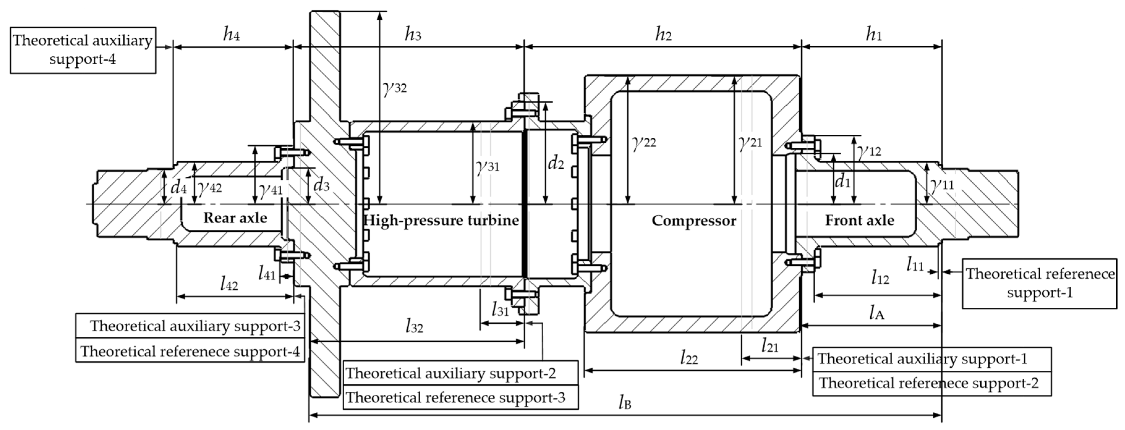
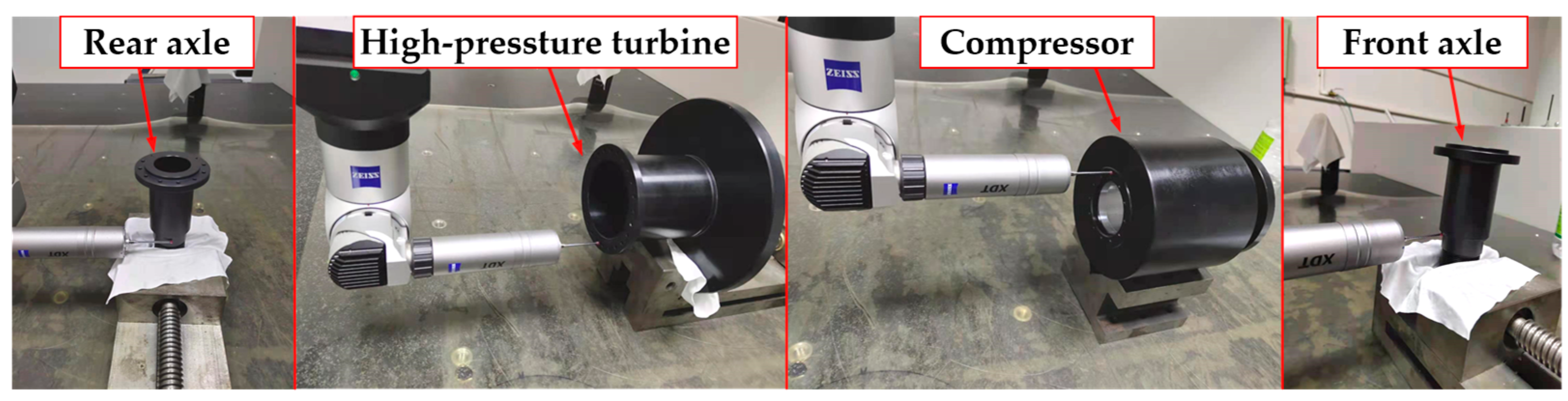
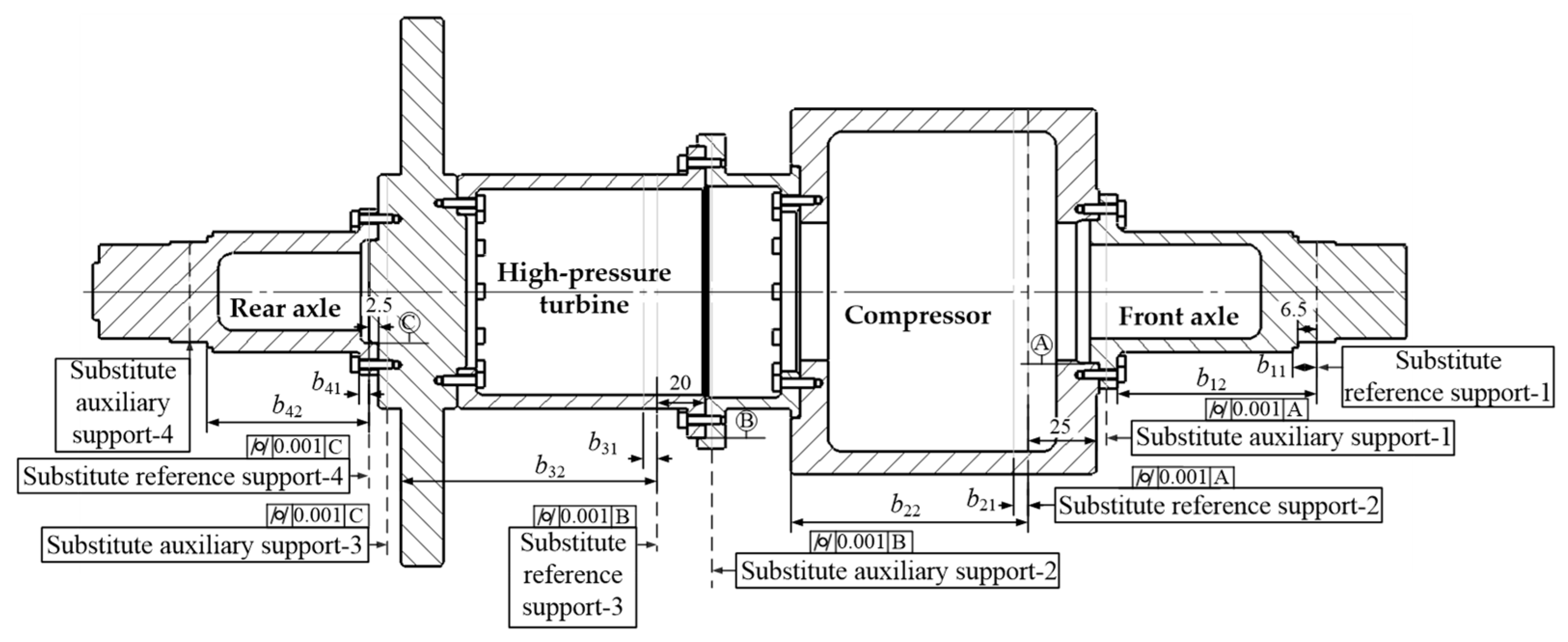
4.1. Measurement of the Geometric Feature Parameters of a Four-Stage Rotor

A four-stage rotor made of 40 Cr, with a surface hardness of HRC 43~55 after heat treatment and a nitriding depth of no less than 0.2 mm for all assembled front edges, was used for the simulation reported in Section 3. The initial parameters of each stage’s rotor were measured according to the geometric feature parameter measurement principle described in Section 3. The measurement equipment used was the Zeiss Spectrum-10166 three-coordinate measuring machine produced by Carl Zeiss AG in Jena, Germany, with an extended uncertainty of 0.7 μm (k = 2) for coordinate measurements in the X, Y, and Z directions within a range of 300 mm.
Figure 15 shows the measurement of the geometric feature parameters for each stage’s rotor. The sampling starting point is the center of the calibrated screw hole of each stage’s rotor, and 120 evenly distributed sampling points are established on both the axial and radial measurement surfaces of the front edge of each stage’s rotor. Table 6 presents the measurement results.

4.2. Measurement of the Mass Feature Parameters of a Four-Stage Reduced-Scale Simulated Rotor

Based on the measurement principle of mass feature parameters described in Section 3, some front edges are concave and cannot be used as direct support points. Therefore, suitable positions are selected on the outer circle of each stage’s rotor as substitute benchmarks, to serve as support points. The newly defined support intercept circle and the radial surface of the front edges on the same side adopt the same machining process, commonly known as “one-cut turning”, to ensure that the coaxiality between the substitute support intercept circle and the theoretical support intercept circle is within 0.001 mm. Figure 16 displays the substitute reference and auxiliary supports selected for each stage’s rotor. The parameters bjk and ljk in the figure have the same meaning and represent the axial position of the two-sided unbalance of each stage’s rotor after the substitute benchmarks are used. These parameters are only input during dynamic balancing machine measurements, but ljk is still used for calculation purposes. The measurement equipment used is the DH20Q dynamic balancing machine produced by the Shanghai Dong yi Jing Test Machine Co., Ltd. (Shanghai, China), with a minimum unbalance resolution of less than or equal to 0.3 g·mm/kg. The test speed is set to 1000 r/min. Figure 17 shows the measurement of the mass feature parameters of each stage’s rotor. The resulting measurements of the two-sided unbalance, its phase angle, the measurement radius, and the support span for each stage’s rotor are shown in Table 7.

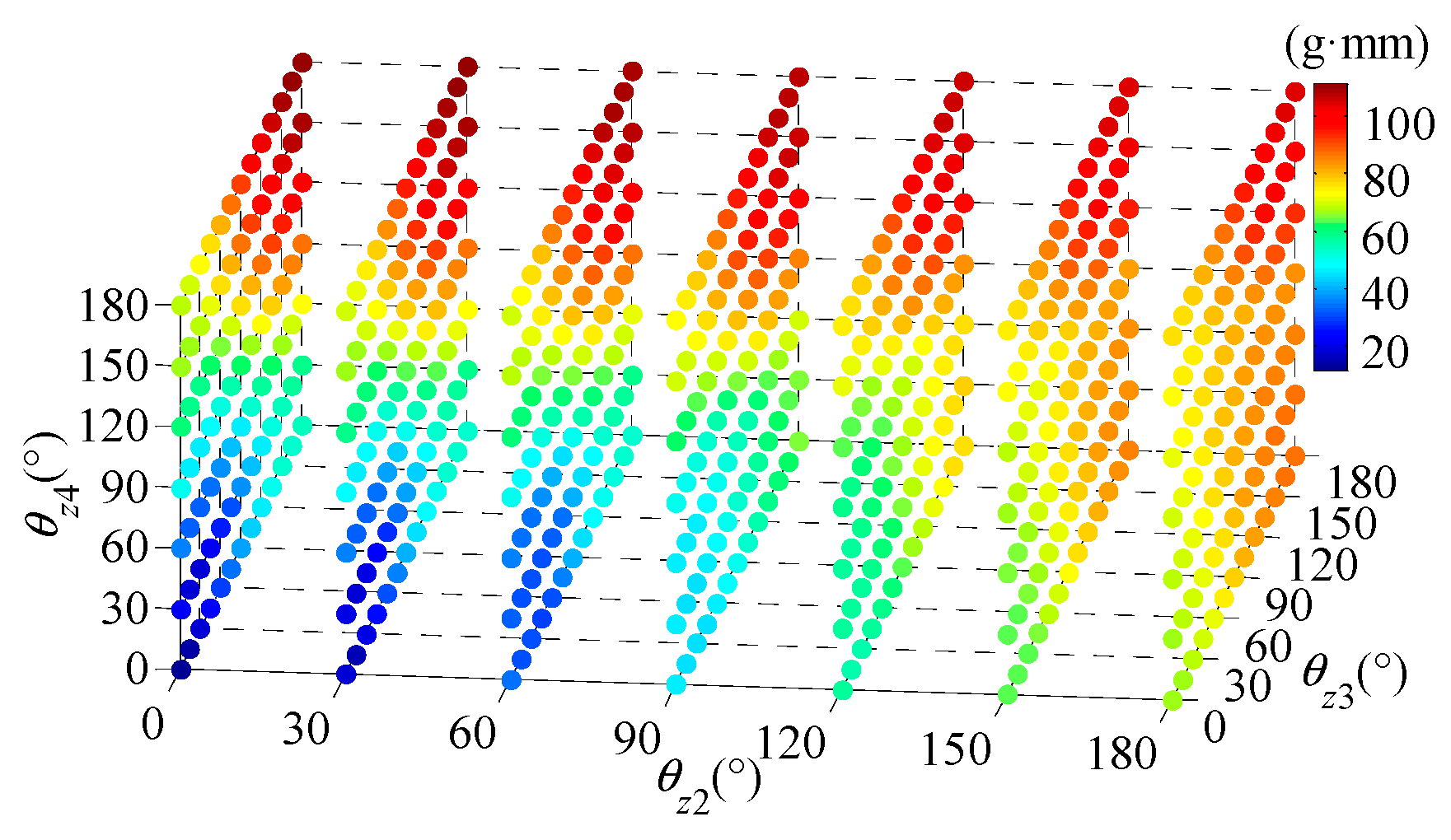
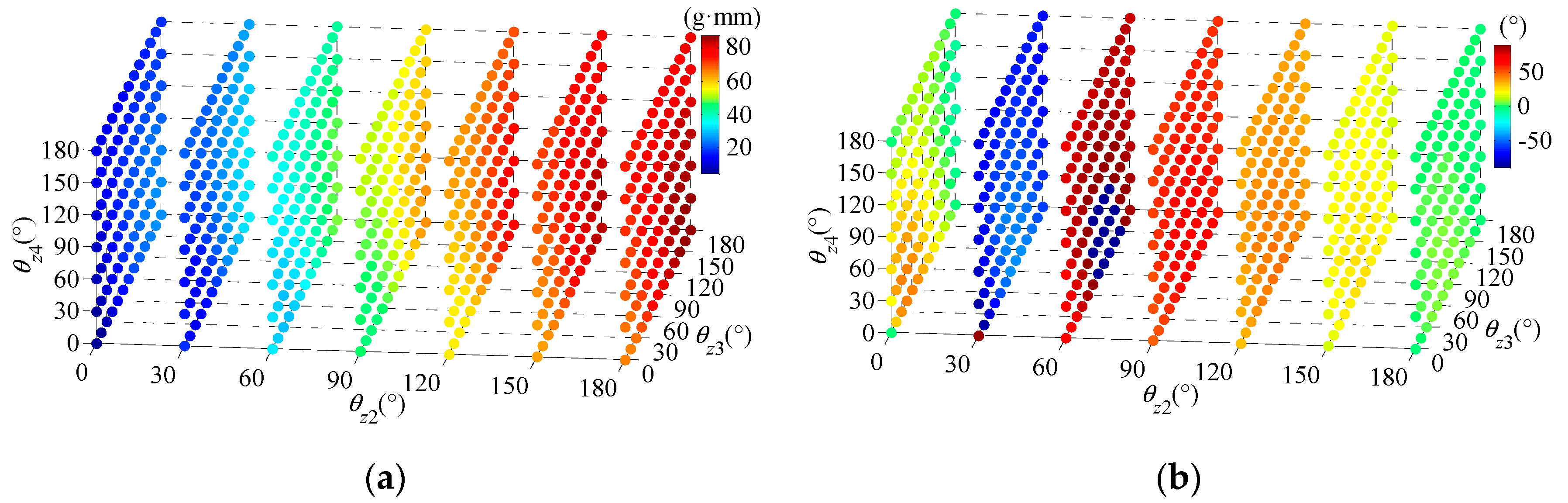
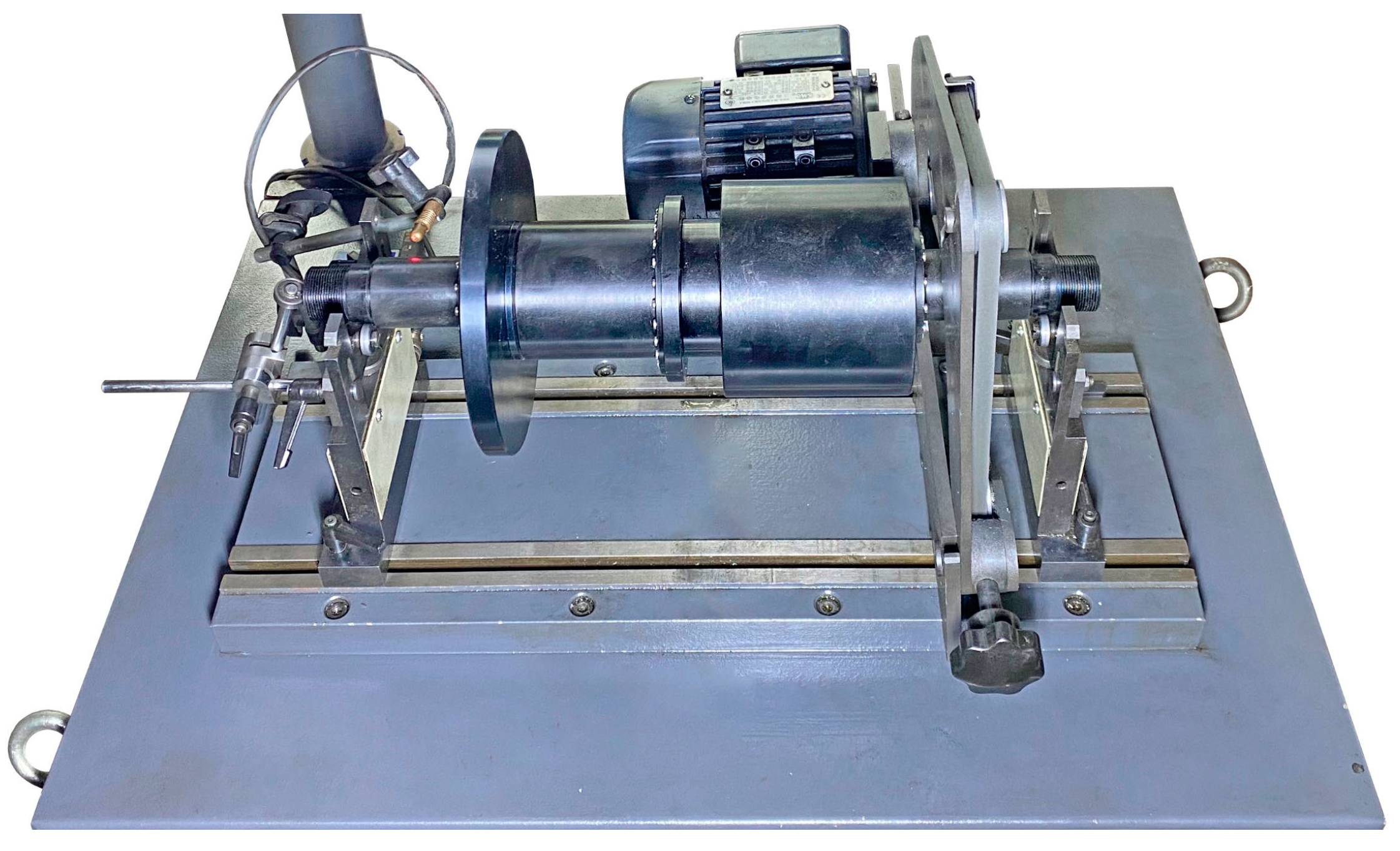
4.3. Testing and Analysis of the Two-Sided Unbalance for the Four-Stage Reduced-Scale Simulated Rotor

Two assembly error transfer models were employed to calculate the two-sided unbalance and its action phases in a four-stage reduced-scale simulated rotor, one of which is proposed in this paper, while the other is the existing model [18,19,25,26,27] constructed during previous research. Based on the measured parameters in Table 6 and Table 7, the simulation in Section 3 is reconstructed. The two models’ prediction accuracies are, thus, compared across the six assembly phase sequences.
Figure 17 shows the measurement of the two-sided unbalance of the four-stage rotor. Table 8 records the measured data, and Table 9 and Table 10 present the two-sided unbalance and action phase obtained by the two models, respectively. Table 11 and Table 12, respectively, provide the relative errors of the calculation results of the two models compared to the measured results. Relative error is the difference between the calculated and measured results divided by the measured results. For a comparison of the calculated action phases, the quoted error is used, which is the difference between the calculated and measured results, divided by 360°.
The above results indicate that the proposed model’s prediction errors of the unbalance on Plane A vary from −9.4% to 8.0% under the six assembly phase sequences. Its prediction errors of the action phases of the unbalance on Plane A vary within the range of −1.9% to 2.2%. Its prediction errors of the unbalance on Plane B vary within the range of −5.4% to 9.6%, and those of the action phases of the unbalance on Plane B vary within the range of −2.5% to 1.7%.
The existing model’s [18,19,25,26,27] prediction errors of the unbalance on Plane A vary from −14.0% to 62.6% under the six assembly phase sequences. Its prediction errors of the action phases of the unbalance on Plane A vary within the range of −37.8% to 19.2%. Its prediction errors of the unbalance on Plane B vary within the range of −3.5% to 44.9%, and those of the action phases of the unbalance on Plane B vary within the range of −10.6% to 40.6%.
Compared with the experimental results, the proposed model’s maximum prediction errors for the two-sided unbalance and its action phases of the four-stage rotor are 9.6% and 2.5%, respectively. In contrast, the existing model [18,19,25,26,27] has maximum prediction errors of 62.6% and 40.6% for the same input parameters. Therefore, the model proposed in this paper reduces the maximum prediction errors of the two-sided unbalance and its action phases of a four-stage rotor by 53.0% and 38.1%, respectively, compared to the existing model [18,19,25,26,27].
The reason for the significant errors in the existing assembly error transfer model’s predictions lies in the common issue of adopting the longitudinal axis of the first-stage rotor base as the reference for calculating mass eccentricity errors, rather than the actual rotation axis of the multi-stage rotor, which prevents accurate determination of the real unbalance and its corresponding phase.

5. Conclusions

In this study, six different assembly phase sequences were used to assemble a four-stage rotor, and its two-sided unbalance and action phases were measured under each of these assembly phase sequences using a dynamic balancing machine. The experimental results indicate that the maximum prediction errors of the assembly error transfer model proposed in this paper for the four-stage rotor’s two-sided unbalance and action phases are 9.6% and 2.5%, respectively. Moreover, compared to the existing models [18,19,25,26,27], the assembly error transfer model proposed in this paper reduces these maximum prediction errors by 53.0% and 38.1%, respectively.
The significant improvement achieved herein in the prediction accuracy of the two-side unbalance of a multi-stage assembled rotor is mainly attributable to several innovative methods used in the construction process of the assembly error transfer model, which are summarized as follows:
  • According to the principle of homogeneous coordinate matrix transformations, the geometric and mass feature parameters of the rotors at each stage are unified to the same coordinate system, solving the problem of the asynchronous transmission of dual parameters.
  • A linear parameter equation of the actual rotation axis of a multi-stage assembled rotor has been established, and this then reproduced the actual working conditions of the dynamic balance test. Therefore, the true two-side unbalance of a multi-stage assembled rotor can be accurately calculated.
In summation, the prediction model for two-sided unbalance in multi-stage assembled rotors developed in this study exhibits an advancement in prediction accuracy when contrasted with the existing models. Nonetheless, it should be noted that the comparative analysis was confined to a four-stage simulated model. The degree to which the prediction accuracy of the proposed model is enhanced for multi-stage rotors comprising five, six, or additional stages remains to be determined. This constitutes an area for future research to explore and substantiate.

Author Contributions

Conceptualization, L.S.; methodology, L.S.; validation, L.S. and Y.C.; formal analysis, L.S.; investigation, L.S.; resources, L.S.; data curation, L.S.; writing—original draft preparation, L.S.; writing—review and editing, Y.C.; visualization, L.S.; supervision, L.S.; project administration, L.S.; funding acquisition, L.S. All authors have read and agreed to the published version of the manuscript.

Funding

This research was funded by the National Natural Science Foundation of China General Project, Number 52275366. The authors are grateful for the financial support.

Data Availability Statement

Data are contained within the article.

Acknowledgments

The authors acknowledge Shihai Cui from the College of Mechanical Engineering, Tianjin University of Science and Technology, for actively supporting this research.

Conflicts of Interest

The authors declare no conflicts of interest.

References

  1. Zhang, Y.; Wang, W.; Wei, D. Unbalance response and stability analysis of a high-speed turbocharger bearing-rotor system. Tribol. Lett. 2022, 42, 620–631. [Google Scholar]
  2. Yang, W.; Liang, M.; Wang, L. Research on unbalance response characteristics of gas turbine blade-disk rotor system. J. Vibroeng. 2018, 20, 1676–1690. [Google Scholar] [CrossRef]
  3. Qiuxiao, W.; Fei, W. A new vibration mechanism of balancing machine for satellite-borne spinning rotors. Chin. J. Aeronaut. 2014, 27, 1318–1326. [Google Scholar]
  4. Dinggen, L.; Jiguang, C.; Junwen, W. The design and analysis of vibration structure of vertical dynamic balancing machine. Acta. Mech. Solida. Sin. 2004, 17, 11–17. [Google Scholar]
  5. Chen, Z.; Liu, Y.; Zhou, P. Assembly success rate calculation method for aero-engine based on improved taguchi method. J. Propuls. Technol. 2018, 39, 653–659. [Google Scholar]
  6. Wang, C.; Yu, H.; Zhang, W. Object-oriented aero-engine assembly models. Int. J. Internet Manuf. Serv. 2010, 2, 354–364. [Google Scholar] [CrossRef]
  7. Chen, Y.; Cui, J.; Sun, X. An unbalance optimization method for a multi-stage rotor based on an assembly error propagation model. Appl. Sci. 2021, 11, 887. [Google Scholar] [CrossRef]
  8. Hussain, T.; Yang, Z.; Popov, A. Straight-build assembly optimization: A method to minimize stage-by-stage eccentricity error in the assembly of axisymmetric rigid components (two-dimensional case study). J. Manuf. Sci. Eng. 2011, 133, 031014. [Google Scholar] [CrossRef]
  9. Hussain, T.; Mcwilliam, S.; Popov, A. Geometric error reduction in the assembly of axis-symmetric rigid components: A two-dimensional case study. Proc. Inst. Mech. Eng. Part B J. Eng. Manuf. 2012, 226, 1259–1274. [Google Scholar] [CrossRef]
  10. Hussain, T.; Yasinshaikh, G.; Shaikh, A. Variation propagation control in straight-build assemblies: 2d case study. Mehran Univ. Res. J. Eng. Technol. 2013, 32, 71–80. [Google Scholar]
  11. Yang, Z.; Popov, A.; Mcwilliam, S. Variation propagation control in mechanical assembly of cylindrical components. J. Manuf. Syst. 2012, 31, 162–176. [Google Scholar] [CrossRef]
  12. Yang, Z.; Hussain, T.; Popov, A. A comparison of different optimization techniques for variation propagation control in mechanical assembly. Mater. Sci. Eng. IOP 2011, 26, 012017. [Google Scholar] [CrossRef]
  13. Yang, Z.; Hussain, T.; Popov, A. Novel optimization technique for variation propagation control in an aero-engine assembly. J. Eng. Manuf. 2011, 225, 100–111. [Google Scholar] [CrossRef]
  14. Yang, Z.; Mcwilliam, S.; Popov, A. Dimensional variation propagation analysis in straight-build mechanical assemblies using a probabilistic approach. J. Manuf. Syst. 2013, 32, 348–356. [Google Scholar] [CrossRef]
  15. Shan, F.; Li, Z.; Zhu, B. Modeling and analysis of assembling deviation of typical aero-engine rotor parts. Manuf. Autom. 2015, 37, 100–103. (In Chinese) [Google Scholar]
  16. Meng, X.; Shan, F. Prediction of assembly quality of aero-engine rotor parts. Manuf. Autom. 2016, 38, 61–65. (In Chinese) [Google Scholar]
  17. Zhang, N.; Wu, Y.; Yang, R.; Xie, G. Digital simulation and analysis of assembly-deviation prediction based on measurement data. Appl. Sci. 2023, 13, 12193. [Google Scholar] [CrossRef]
  18. Wang, L.; Sun, C.; Tan, J. Improvement of location and orientation tolerances propagation control in cylindrical components assembly using stack-build assembly technique. Assem. Autom. 2015, 35, 358–366. [Google Scholar] [CrossRef]
  19. Sun, Y.; Guo, J.; Hong, J. Repair decision based on sensitivity analysis for aero-engine assembly. Int. J. Precis. Eng. Man. 2019, 20, 347–362. [Google Scholar] [CrossRef]
  20. Mu, X.; Wang, Y.; Yuan, B.; Sun, W.; Liu, C.; Sun, Q. A New assembly precision prediction method of aeroengine high-pressure rotor system considering manufacturing error and deformation of parts. J. Manuf. Syst. 2021, 61, 112–124. [Google Scholar] [CrossRef]
  21. Zhu, L.; Yang, Y.; Huang, H.; Bouzid, A.H.; Hong, J. A novel method to predict the concentricity of aero-engine rotor considering the assembly process of bolted flange joints. In Proceedings of the Pressure Vessels and Piping Conference, Las Vegas, NV, USA, 17–22 July 2022; American Society of Mechanical Engineers: New York, NY, USA, 2022; Volume 86151, p. V002T02A008. [Google Scholar]
  22. Shi, S.; Liu, J.; Gong, H.; Shao, N.; Anwer, N. Assembly accuracy analysis and phase optimization of aero-engine multistage rotors considering surface morphology and non-uniform contact deformation. Precis. Eng. 2024, 88, 595–610. [Google Scholar] [CrossRef]
  23. Zhang, B.; Lu, H.; Liu, S.; Yang, Y.; Sang, D. Aero-engine rotor assembly process optimization based on improved harris hawk algorithm. Aerospace 2023, 10, 28. [Google Scholar] [CrossRef]
  24. Zhang, X.; Fu, X.; Fu, B.; Du, H. Multi-objective optimization of aeroengine rotor assembly based on tensor coordinate transformation and NSGA-II. CIRP J. Manuf. Sci. Technol. 2024, 51, 190–200. [Google Scholar] [CrossRef]
  25. Liu, Y.; Zhang, M.; Sun, C. A method to minimize stage-by-stage initial unbalance in the aero engine assembly of multistage rotors. Aerosp. Sci. Technol. 2019, 85, 270–276. [Google Scholar] [CrossRef]
  26. Sun, C.; Li, C.; Liu, Y. Prediction method of concentricity and perpendicularity of aero engine multistage rotors based on PSO-BP neural network. IEEE Access 2019, 7, 132271–132278. [Google Scholar] [CrossRef]
  27. Sun, C.; Liu, Z.; Liu, Y. An adjustment method of geometry and mass centers for precision rotors assembly. IEEE Access 2019, 7, 169992–170002. [Google Scholar] [CrossRef]
Figure 1. Geometric feature parameters of a single-stage rotor.
Machines 12 00503 g001
Figure 2. Mass feature parameters of a single-stage rotor.
Machines 12 00503 g002
Figure 3. The assembly calculation processes of a two-stage rotor [25].
Machines 12 00503 g003
Figure 4. Barycenter coordinate measurements of the three-stage simulated rotor in SOLIDWORKS: (a) the first assembly state; (b) the second assembly state.
Machines 12 00503 g004
Figure 5. A two-stage rotor assembly.
Machines 12 00503 g005
Figure 6. Decomposition of two-sided unbalance in a rotor dynamic balance test.
Machines 12 00503 g006
Figure 7. Decomposition of the two-sided unbalance of a two-stage rotor.
Machines 12 00503 g007
Figure 8. A scaled model of the four-stage high-pressure simulated rotor of an aero engine.
Machines 12 00503 g008
Figure 9. The unbalance UA and its action phase ζA on Plane A in simulation: (a) UA; (b) ζA.
Machines 12 00503 g009
Figure 10. The unbalance UB and its action phase ζB on Plane B in simulation: (a) UB; (b) ζB.
Machines 12 00503 g010
Figure 11. Maximum comprehensive unbalance under all assembly phase sequences in simulation.
Machines 12 00503 g011
Figure 12. The unbalance UA and its action phase ζA on Plane A: (a) UA; (b) ζA.
Machines 12 00503 g012
Figure 13. The unbalance UB and its action phase ζB on Plane B: (a) UB; (b) ζB.
Machines 12 00503 g013
Figure 14. Maximum comprehensive unbalance under all assembly phase sequences.
Machines 12 00503 g014
Figure 15. Measurement of the geometric feature parameters for each stage’s rotor [26].
Machines 12 00503 g015
Figure 16. The substitute benchmarks and auxiliary support of the four-stage reduced-scale simulated rotor.
Machines 12 00503 g016
Figure 17. Measurement scene of the two-sided unbalance of the four-stage rotor.
Machines 12 00503 g017
Table 1. Geometric feature parameters of each stage’s rotor of the three-stage simulated rotor.
Stage Numbercj (mm)θj (°)pj (mm)hj (mm)δj (°)dj (mm)
10.00500.005700100
20.00500.005700100
30.00500.005700100
Table 2. Barycenter coordinates of the three-stage rotor, simulated in two assembly states.
Stage NumberBarycenter Coordinate Vector of
the First Assembly State (mm)
Barycenter Coordinate Vector of
the Second Assembly State (mm)
1[0.003 626, 0.000 117, 34.999 160][0.003 626, 0.000 117, 34.999 160]
2[0.007 751, 0.000 117, 104.999 916][0.007 207, 0.001 914, 104.999 916]
3[0.010 126, 0.000 117, 174.999 916][0.005 830, 0.005 689, 174.999 916]
Table 3. Geometric feature parameters of each stage’s rotor of the four-stage simulated rotor.
Stage Numbercj (mm)θj (°)pj (mm)hj (mm)δj (°)dj (mm)
10.0200.0270025
20.02900.021389051
30.021800.0211518017.5
40.022700.026027017
Table 4. Mass feature parameters of each stage’s rotor of the four-stage simulated rotor.
Stage NumberUnbalanced Mass
Point Number
γjk (mm)ljk (mm)ujk (g)φjk (°)
112120.50
23463.50.50
2164300.50
2641080.50
3141250.50
2961070.50
41296.50.50
221600.50
Table 5. Calculation results of two assembly error transfer models of two-sided unbalance.
Assembly Phase
Sequence
Calculation Basis:
Actual Rotation Axis
Calculation Basis:
Longitudinal
Axis of Datum Plane
UA (g·mm)
ζA (°)
UB (g·mm)
ζB (°)
UA (g·mm)
ζA (°)
UB (g·mm)
ζB (°)
114.46 ∠ −6719.59 ∠ −5334.01 ∠ −8940.57 ∠ −69
234.04 ∠ 8940.50 ∠ 6919.53 ∠ 5314.46 ∠ −67
318.25 ∠ 0111.69 ∠ 062.70 ∠ −5358.99 ∠ 11
44.51 ∠ 011.45 ∠ 055.46 ∠ −6466.10 ∠ −10
585.10 ∠ 2047.61 ∠ 3233.47 ∠ 8380.86 ∠ −7
663.43 ∠ 5785.71 ∠ −684.50 ∠ 011.34 ∠ 0
Table 6. Geometric feature parameters of each stage’s rotor.
Stage Numbercj (mm)θj (°)pj (mm)hj (mm)δj (°)dj (mm)
10.015 31080.013 070.322 52125.016 0
20.094 42160.023 5137.963 126150.929 6
30.096 3340.035 1114.896 617717.509 5
40.049 6850.019 460.113 09917.023 9
Table 7. Mass feature parameters of each stage’s rotor.
Stage NumberUnbalanced Mass
Point Number
γjk (mm)ljk (mm)ujk (g)φjk (°)
112120.2671
23463.50.23233
2164300.39112
2641080.3124
3141250.2896
2961070.53113
41296.50.1375
221600.11198
Table 8. Measured data of the two-sided unbalance and its action phases in the four-stage rotor.
Assembly Phase SequencesUA (g·mm)ζA (°)UB (g·mm)ζB (°)
θz2 = 30°, θz3 = 30°, θz4 = 30°18.4111045.55106
θz2 = 60°, θz3 = 60°, θz4 = 60°25.318242.8145
θz2 = 90°, θz3 = 180°, θz4 = 180°31.025765.4367
θz2 = 30°, θz3 = 60°, θz4 = 0°20.9812346.8778
θz2 = 0°, θz3 = 150°, θz4 = 90°27.6515358.90−4
θz2 = 180°, θz3 = 0°, θz4 = 0°22.1814051.42−11
Table 9. The two-sided unbalance and its action phases in the four-stage rotor, calculated using the model proposed in this paper.
Assembly Phase SequencesUA (g·mm)ζA (°)UB (g·mm)ζB (°)
θz2 = 30°, θz3 = 30°, θz4 = 30°19.8911546.70107
θz2 = 60°, θz3 = 60°, θz4 = 60°22.948946.9241
θz2 = 90°, θz3 = 180°, θz4 = 180°29.885068.6862
θz2 = 30°, θz3 = 60°, θz4 = 0°21.3511944.3569
θz2 = 0°, θz3 = 150°, θz4 = 90°26.6514759.572
θz2 = 180°, θz3 = 0°, θz4 = 0°23.1014850.37−13
Table 10. The two-sided unbalance and its action phases in the four-stage rotor, calculated using the existing model [18,19,25,26,27].
Assembly Phase SequencesUA (g·mm)ζA (°)UB (g·mm)ζB (°)
θz2 = 30°, θz3 = 30°, θz4 = 30°29.94256.7170
θz2 = 60°, θz3 = 60°, θz4 = 60°30.8815162.059
θz2 = 90°, θz3 = 180°, θz4 = 180°26.6711365.2045
θz2 = 30°, θz3 = 60°, θz4 = 0°31.30059.4440
θz2 = 0°, θz3 = 150°, θz4 = 90°29.151771.04−14
θz2 = 180°, θz3 = 0°, θz4 = 0°23.254049.62135
Table 11. The errors between the results calculated by the model proposed in this paper and the measured results.
Assembly Phase SequencesErrors of UA (%)Errors of ζA (%)Errors of UB (%)Errors of ζB (%)
θz2 = 30°, θz3 = 30°, θz4 = 30°8.01.42.50.3
θz2 = 60°, θz3 = 60°, θz4 = 60°−9.41.99.6−1.1
θz2 = 90°, θz3 = 180°, θz4 = 180°−3.7−1.95.0−1.4
θz2 = 30°, θz3 = 60°, θz4 = 0°1.8−1.1−5.4−2.5
θz2 = 0°, θz3 = 150°, θz4 = 90°−3.6−1.71.11.7
θz2 = 180°, θz3 = 0°, θz4 = 0°4.12.2−2.0−0.6
Table 12. The errors between the results calculated by the existing model [18,19,25,26,27] and the measured results.
Assembly Phase SequencesErrors of UA (%)Errors of ζA (%)Errors of UB (%)Errors of ζB (%)
θz2 = 30°, θz3 = 30°, θz4 = 30°62.6−30.024.5−10.0
θz2 = 60°, θz3 = 60°, θz4 = 60°22.019.244.9−10.0
θz2 = 90°, θz3 = 180°, θz4 = 180°−14.015.6−0.4−6.1
θz2 = 30°, θz3 = 60°, θz4 = 0°49.2−34.226.8−10.6
θz2 = 0°, θz3 = 150°, θz4 = 90°5.4−37.820.6−2.8
θz2 = 180°, θz3 = 0°, θz4 = 0°4.8−27.8−3.540.6
Disclaimer/Publisher’s Note: The statements, opinions and data contained in all publications are solely those of the individual author(s) and contributor(s) and not of MDPI and/or the editor(s). MDPI and/or the editor(s) disclaim responsibility for any injury to people or property resulting from any ideas, methods, instructions or products referred to in the content.

