Abstract
The metallic components of an electric machine exert a notable impact on the electromagnetic transmission between an external recipient and an internal shaft sensor. The RTMS (rotor temperature monitoring system) is aimed at boosting power transfer in the machine, regardless of the considerable impact of its components. This research assesses the influence of the components of an electric machine on shaft sensor transmission and specifically addresses the packaging needs of the receiver antenna. The study includes a comparative analysis of two antennas. HFSS (high frequency structure simulator) simulation was utilized to identify the antenna with a superior propagation factor. The principal contribution of this paper is the assessment of how the electrical machine body affects the transmission and propagation of rotor sensor signals, establishing a connection between these effects and the packaging criteria for the receiver antenna. Moreover, the paper presents an antenna design that capitalizes on the electrical machine body to enhance the power transmission effectiveness. The final section of this paper encompasses the experimental results obtained from the implementation of the RN171 antenna on the electrical machine, provides valuable insights into the propagation characteristics, and contributes to a comprehensive understanding of the electromagnetic dynamics within the system.
1. Introduction
Rotating electrical machines are ubiquitous across numerous sectors, and their monitoring has become a constant concern in industrial domains such as aviation and nuclear power. Surveillance techniques play a critical role in ensuring the reliability of industrial systems, preventing failures that could lead to physical damage [1,2]. Typically, the success of these techniques hinges on a thorough understanding of both internal and external characteristics of the machine. Various monitoring methods have been proposed [3,4]. Generally, these methods can be categorized as human experience-based knowledge methods, analytical redundancy methods based on mathematical modeling of the system, and signal modeling methods. The challenge posed by using these various methods lies in the fact that internal parameters (rotational) are not practically accessible. To address these issues, we propose a new technique for monitoring electrical machines and primarily for the detection of rotational defects. This technique relies on a wireless transmission chain that allows for online supervision of various parameters. Indeed, for several years, the market for wireless networks has undergone significant evolution and continues to do so to offer users new multimedia services [5,6].
The effectiveness of communication systems in electrical machines is significantly influenced by the complexity of their components [7]. Our research aims to explore how the limited space within the transmission module impacts communication performance. To facilitate this investigation, one antenna is placed inside the machine, while another is fixed externally. Understanding the operational dynamics of these antennas is crucial for designing an efficient telecommunication network within electrical machines. Therefore, this paper revisits the fundamental properties of antennas to evaluate how various components of electrical machines affect their operation patterns. By doing so, we seek to optimize communication system performance and propose an optimal design framework.
The unique challenges posed by the geometric constraints, limited space and material composition of electrical machines remain underexplored. To address these challenges, we utilize a rotor temperature monitoring system (RTMS), which employs wireless radio frequency transmission to monitor the machine’s rotor temperature during operation [8]. Enhancing the direct communication quality of RTMS has involved implementing various telecommunications techniques, including radiofrequency characterization.
The importance of RTMS cannot be overstated, as failures in electrical machines can lead to significant disruptions in production lines, affecting costs, quality, and safety [9,10]. Ensuring the efficient operation of these machines is paramount [11,12]. Wireless communication offers a promising approach for real-time monitoring of electrical machines, particularly in detecting faults when parameters deviate from their normal ranges [13]. However, integrating wireless communication into the control of electrical machines presents several challenges, including electromagnetic compatibility issues among devices [14]. These challenges stem from factors such as device geometry, confined spaces, and the materials used in electrical machine components, as well as the electromagnetic flux within rotating machines and the presence of electromagnetic fields from rotating modules.
Our previous research highlighted that low-frequency flux within machines does not interfere with high-frequency transmitters. Experimental findings from radio monitoring systems within rotating electrical machines revealed significant fluctuations in received power and rapid fading of the wireless channel due to transmitter rotation. Additionally, a slight reduction in signal amplitude was noted when the emitter was positioned within the electric machine [15]. Similarly, Zeng’s study examined the influence of vehicle components on electromagnetic (EM) propagation within the tire pressure monitoring system (TPMS). The study suggested an antenna design that leverages vehicle components to enhance power efficiency. Thus, optimizing antenna design to harness surface electromagnetic waves (EMWs) induced on EM bodies is essential for achieving reliable communication.
Our research explores the influence of various factors on signal transmission between RTMS sensors positioned within a rotor and a central receiver located outside the electrical machine. It evaluates how the structure of the electrical machine impacts the transmission and propagation of signals from rotor sensors. Additionally, it illustrates that RTMS antennas designed to capitalize on surface waves induced on the electrical machine’s body can surpass the performance of RTMS antennas optimized for free space transmission and reception. The final section of this paper encompasses the experimental results obtained from the implementation of the RN171 antenna on the electrical machine, providing valuable insights into the propagation characteristics and contributing to a comprehensive understanding of the electromagnetic dynamics within the system.
2. RTMS (Rotor Temperature Monitoring System) Design
Wireless data transmission using radio signals employs electromagnetic wave propagation (EMWP). In the context of collecting parameters from rotating electric machines, the monitoring system serves as a crucial method for data transmission in rotational environments. This technology is widely used in aerospace, industry, automotive, and other sectors due to its broad bandwidth, excellent penetration, and long-range capabilities [16]. Common examples include systems for monitoring car and truck tire pressure and devices for data collection from rotating components [17].
A radio monitoring system typically consists of a rotating transmitter attached to the moving part and a stationary receiver nearby. Its primary goal is to ensure reliable and accurate wireless transmission of data and signals from rotating components to the stationary receiver, especially in dynamic environments. Various sensors, such as strain gauges, thermocouples, thermistors, pressure transducers, and accelerometers, convert physical measurements into electrical signals, which are then transmitted wirelessly without physical connections. A schematic of a standard radio monitoring system is shown in Figure 1.
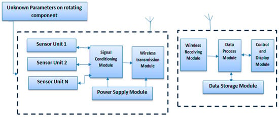
Figure 1.
Diagram illustrating the radio monitoring system for rotating components.
The rotor temperature monitoring system (RTMS) illustrates a paradigm shift in rotorcraft technology, seamlessly integrating advanced sensors and IoT capabilities within the framework of Industry 4.0 [18]. By harnessing the power of IoT, the RTMS transforms traditional rotor temperature monitoring into a dynamic, data-driven process where information is continuously transmitted and processed in a cloud-based infrastructure. Through sophisticated algorithms and machine learning techniques, the RTMS not only monitors temperature variations but also predicts potential anomalies and preemptively identifies maintenance needs, ushering in a new era of predictive maintenance in rotorcraft industry. Additionally, the RTMS boasts unparalleled precision and reliability, with sensors calibrated to nanoscale accuracy, ensuring the capture of even the slightest temperature fluctuations. This level of precision empowers operators with actionable insights, enabling them to optimize rotorcraft performance, extend component lifespans, and enhance overall operational safety. As rotorcraft continue to evolve in complexity and operational demands, the RTMS stands as a testament to innovation, driving the industry towards greater efficiency, reliability, and sustainability in aerial mobility.
The applications of the rotor temperature monitoring system (RTMS) are vast and varied, spanning across multiple industries where rotorcraft plays a crucial role [19]. In the aviation sector, RTMS finds extensive utility in commercial and military rotorcraft, ensuring optimal performance and safety during flight operations [20]. It serves as a vital tool for monitoring rotor temperatures in helicopters, tiltrotors, and other rotary-wing aircraft, facilitating proactive maintenance and preventing catastrophic failures. Additionally, RTMS can be deployed in industries like marine transportation, where it monitors the temperature of ship propellers, contributing to the reliability and efficiency of marine vessels [21]. Moreover, in the context of research and development, RTMS can serve as a valuable asset for testing and validation of new rotorcraft designs, providing crucial data for performance optimization and safety enhancement [22]. With its versatility and reliability, RTMS stands as a pivotal technology in ensuring the integrity and efficiency of rotor systems across diverse applications and industries [22].
The rotating transmitter integrates crucial modules such as a power supply, signal conditioning module, sensor unit, transmitting antenna, and wireless transmission module. Typically housed in robust casing, this transmitter captures raw data from rotating components through various sensor units. The acquired data undergoes processing in the signal conditioning module before being transmitted to the wireless module.
Conversely, the stationary receiver includes a data processing module, control unit, wireless receiving module, receiving antenna, display module, and data storage module. The receiving antenna detects and demodulates the frequency-modulated (FM) signal using the wireless receiving module [23]. The demodulated signal is then directed towards the control and display module via a designated bus, or it may be temporarily stored in the data storage module.
Earlier research endeavors predominantly concentrated on forecasting electromagnetic wave propagation (EMWP) characteristics in scenarios featuring stationary or moving wireless transceiver systems. As a result, the principal aim of this paper is to undertake an initial examination of EMWP characteristics in rotating environments and institute a testing setup for evaluating EMW propagation features of both stationary and rotating transmitters.
“The IoT in Industry 4.0” refers to the integration of the Internet of Things (IoT) technologies within the framework of Industry 4.0, which represents the fourth industrial revolution. In this context, IoT plays a pivotal role in enhancing connectivity, communication, and automation in industrial processes. The synergy of Industry 4.0 and IoT involves embedding smart sensors, devices, and actuators into physical assets, machinery, and production systems. These interconnected devices collect real-time data and communicate with each other over a network, enabling intelligent decision-making, predictive maintenance, and optimization of manufacturing processes. The goal is to create a more efficient, flexible, and responsive industrial ecosystem where data-driven insights contribute to improved productivity, resource utilization, and overall operational excellence. The integration of IoT in Industry 4.0 signifies a transformative shift in how industries manage and leverage information, fostering innovation and adaptability in the modern industrial landscape. In the specific context of controlling electrical machines, IoT 4.0 facilitates wireless communication between the electrical machine and its control system [24,25], allowing for remote monitoring and management of the machine. This capability enhances operational efficiency and flexibility. Sensors with IoT 4.0 can be seamlessly integrated into the electric machine to collect data, enabling analysis for optimized operation and proactive breakdown prevention. In this regard, our proposed system, RTMS, aligns seamlessly with the principles of IoT Industry 4.0 [26,27].
Fundamentally, a RTMS involves wireless RF propagation connecting a fixed sender module situated within the EM to a stationary receiver positioned outside. This technological innovation has revolutionized the manufacturing sector by enhancing overall productivity, minimizing downtime, and enabling predictive maintenance.
It is crucial to note that this system serves a dual purpose: assessing propagation quality in the machine and detecting rotor temperature [9,28]. In this research, the data control system follows the IEEE 802.11 protocol.
Providing a comprehensive and dependable analysis of the RF channel is imperative to ensure the effectiveness of a rotor temperature monitoring system. Key components in characterizing the RTMS encompass the carcass, stator, rotor, and shaft. These elements notably impact the parameters of the sensor antenna, including the radiation pattern and antenna gain. It is important to highlight that the propagation between the shaft and the receiver doesn’t traverse open space; instead, it passes through the body of the electrical machine and internal equipment.
3. Modeling Electromagnetic Propagation in a Rotating Machine
3.1. Modeling and Structure
In this section, we will focus on modeling the asynchronous machine using the finite element method in the Ansys HFSS environment. Due to its high performance, Ansys HFSS allows for more precise analysis in motor design and modeling. Designing the electric machine model requires not only knowledge of its structure but also the specifications of the constituent materials and various geometric characteristics.
Communication between the transmitter and receiver is complex due to several factors that increase the complexity of the radio link budget and degrade the overall transmission quality. Transmission within a machine is influenced by these main components:
- Rotor: The metal part of the machine.
- Stator: A complex composite made of various materials that differ widely between models or manufacturers. The associated electrical information is difficult to access and study.
- Flange: A steel component fixed to the stator with bolts or rods.
To examine the maximum power transfer between two monopole antennas—one inside the electrical machine and the other outside—we will develop the expression for the propagation factor, which is inversely proportional to propagation loss.
To study the influence of electrical machine components on electromagnetic propagation, modeling the electrical machine is essential. This requires knowledge of its structure and the specifications of its materials and geometric characteristics [29,30]. The HFSS modeling must consider the same material specifications and geometric characteristics used with Maxwell 2D [31].
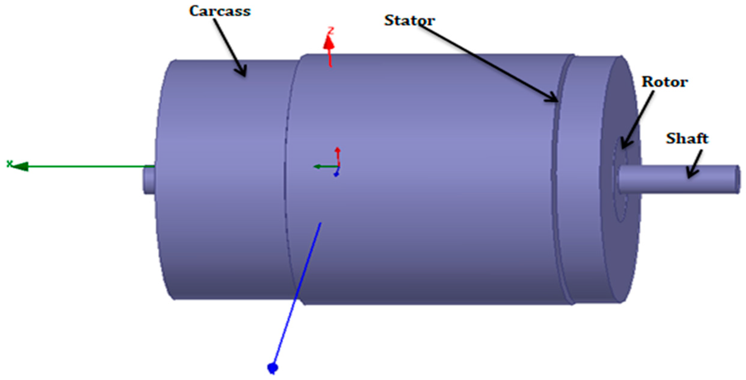
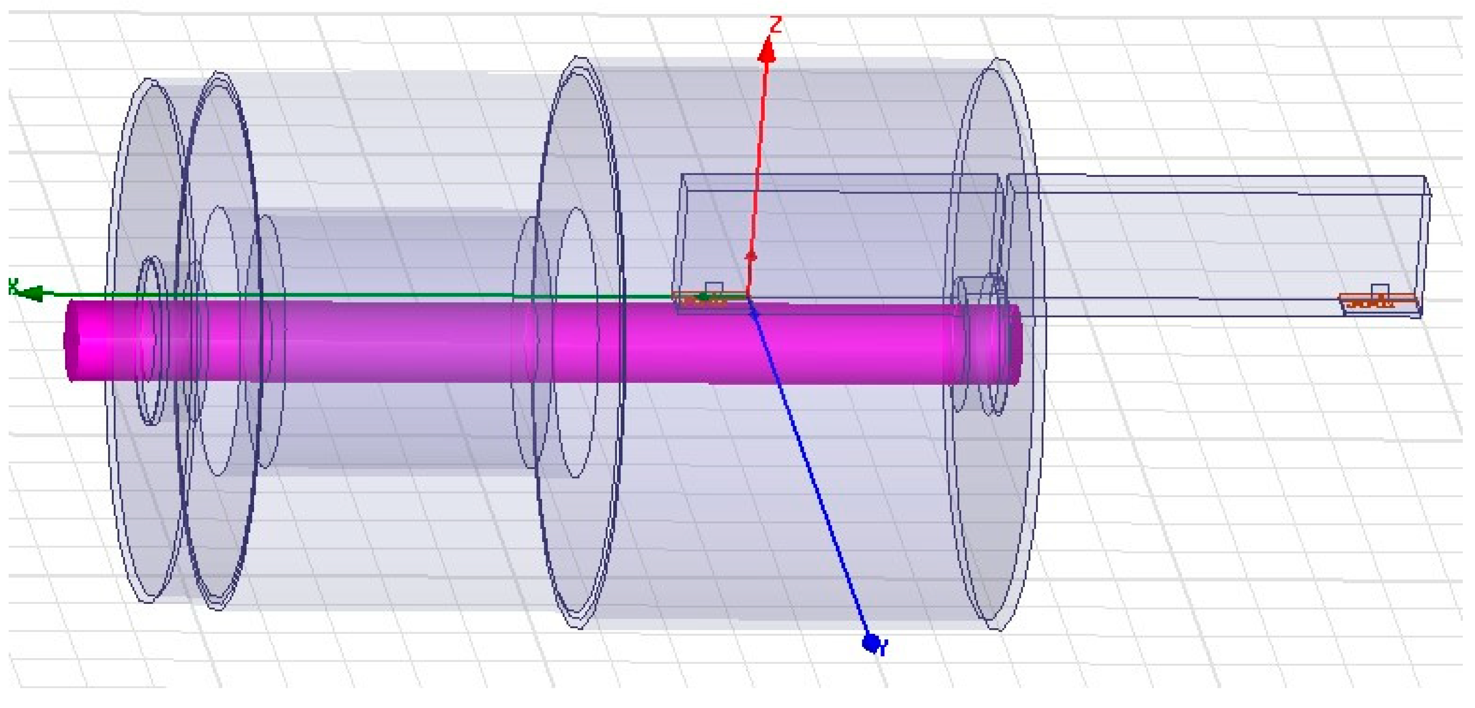
The model includes all elements of the machine, such as a steel shaft, an aluminum rotor, a copper layer, a ferromagnetic stator layer, an aluminum flange, and steel lamination. The shaft has a diameter of 21.6 mm and a length of 285 mm; the rotor has a diameter of 74.5 mm and a length of 79.22 mm; the stator has a diameter of 126 mm and a length of 69 mm; and the flange has a diameter of 135.7 mm and a length of 213 mm. The antenna is placed near the rotor location.
The simplified HFSS simulation model of the electrical machine is shown in Figure 2. Modeling this configuration took approximately 3 h to simulate.
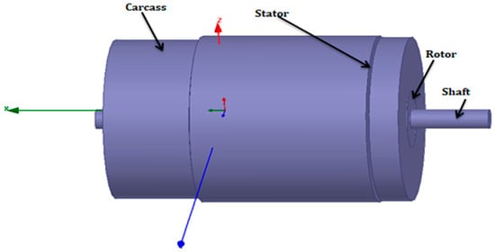
Figure 2.
HFSS implementation of the SM for the squirrel cage induction motor.
3.2. Monopole Antennae Design
The primary objective was to determine the feasibility of signal detection in a rotor- embedded machine (REM). To achieve this, we integrated an appropriate electric circuit and a suitable antenna with the sensor. The chosen monopole satisfied these criteria: efficient and suitable antenna gain, compact size, and stability of antenna parameters across a broad range of rotors and stators.
In theory, multiple antenna types met these criteria, categorically falling within three primary groups: electrical antennas, magnetic antennas, and combinations of both. Antennas like patch antennas, IFAs (inverted-F antennas), and monopole antennas were considered within the scope of applicability [32,33].
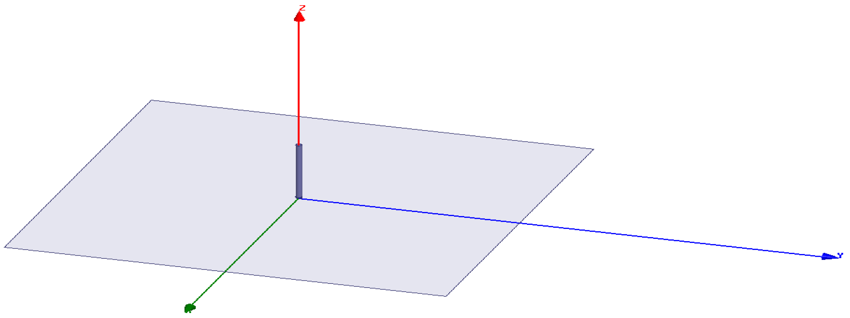
Our initial focus was on the monopole antenna, consisting of a strand positioned above a large metal plane, taking into account wavelengths of two to three lambdas at least.
For our investigation, a design was created featuring a metal piece spanning the surface of a PCB (printed circuit board). A monopole antenna has a height of 3.16 cm and a radius of 0.1 cm. Utilizing HFSS, we simulated this structure, requiring approximately 15 min for the simulation process. Figure 3 visually depicts the HFSS design of the monopole antenna.
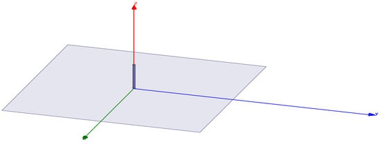
Figure 3.
The design of the monopole antenna.
Our simulations were conducted with two different setups. The first was in an open space above a ground plane situated between two antennas. In the other case, we included all the machine components: rotor, stator, shaft, and carcass.
In both instances, both antennas shared the same position and orientation. To reduce reflection waste, the matching network was fine-tuned separately for each case, setting the corresponding parameters at the zero position.
The propagation factor is [34,35]:
where S11 is the coefficient at the input of the adaptation network and the antenna of the transmitter, S21 is the transmission coefficient from Port 1 to Port 2, S22 is the reflection coefficient at the receiver, et is the efficiency of the transmitting antenna, and er is the radiation efficiency of the receiving antenna.
Following the calculation of parameter S, the actual Fp was derived using Equation (1). The outcomes of the simulation are presented in Table 1.

Table 1.
The calculated Fp.
As shown in the table, the calculated propagation factor (Fp) for electromagnetic transmission and reception decreases with the addition of each component of the rotating machine. This means that as more parts are added to the machine, the efficiency of signal transmission and reception declines. Each new component introduces more obstacles and potential sources of interference, which disrupt the electromagnetic waves and reduce the overall effectiveness of the communication system.
3.3. Design of RN 171 Antennae
The underlying hardware architecture depends on the RN-171 module, incorporating a 32-bit SPARC processor (scalable processor architecture), a real-time clock, a 2.4 GHz radio, a CPU, a crypto accelerator, power management, analog sensor interfaces, and a TCP/IP stack [36].
We chose the RN171-EK specifically for our system’s mobile wireless applications, given its exceptionally minimal energy usage.
The positioning and alignment of the two antennas remained consistent across the four scenarios. Matching parameters were established at the zero position and maintained constantly during rotor rotation. Subsequently, the radiation efficiencies and S-parameters were computed, and the propagation factor Fp was determined by Equation (1).
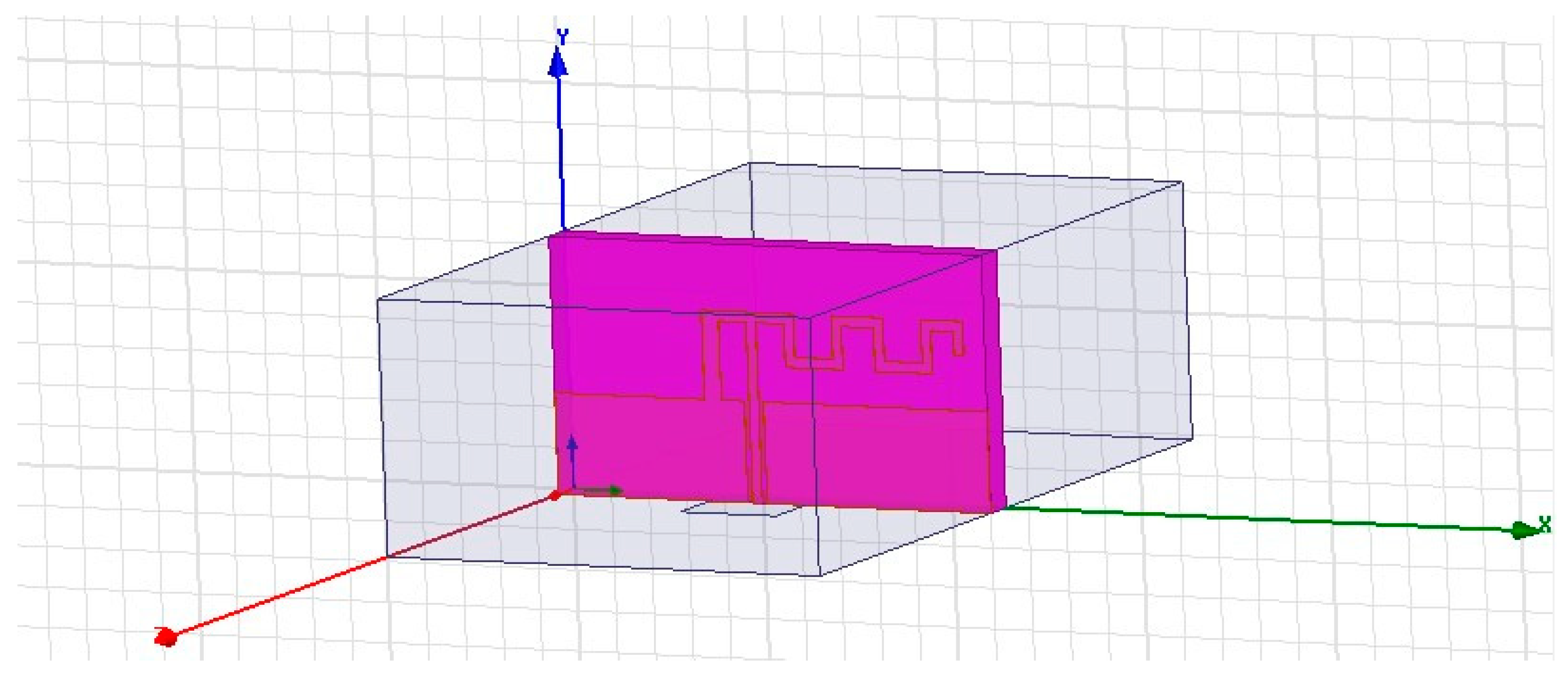
Figure 4 represents the HFSS RN-171 design. The characteristics of the RN-171 module are shown in ref. [8].
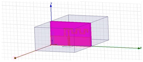
Figure 4.
The RN171 antenna design.
Figure 5 represents the HFSS simulation of two RN-171 antennas with an electrical machine.

Figure 5.
The HFSS simulation of two RN171 antennas with an electrical machine.
Table 2 presents the computed S-parameters and propagation factors for electromagnetic propagation/reception in two scenarios.
Table 2.
Fp for two RN-171 antennas.
The propagation factor closely approaches the maximum achievable when the transmitter is positioned in free space. Clearly, the electrical machine bodies cause significant attenuation in signal propagation.
3.4. Monopole Antenna Performance
The HFSS simulation revealed that the metallic components of the machine significantly influenced the propagation factor (Fp) and the machine’s carcass had a noticeable attenuating effect on signal transmission.
In contrast, it was observed that the monopole antenna exhibited a superior propagation factor in comparison to the RN-171 antenna. Additionally, the monopole antenna radiated uniformly in a specific direction, contributing to a stronger transmitted signal.
The existence of the electrical machine body significantly influences both the input impedance of the antenna and the S21 parameter, thereby affecting the transmission characteristics. This implies that optimizing antennas for their specific operational environment may offer more advantages than designing them exclusively for free-space propagation. Tailoring antennas to leverage the machine components enables a meaningful improvement in the efficiency of EM communication.
4. Experimental Results
In this section, we will validate the simulations discussed earlier in the paper. We conducted experiments on a single-phase squirrel cage asynchronous machine using two RN-171 antennas introduced in Section 3.3.
Figure 6 shows the placement of the RN-171 transmitter inside the electrical machine.
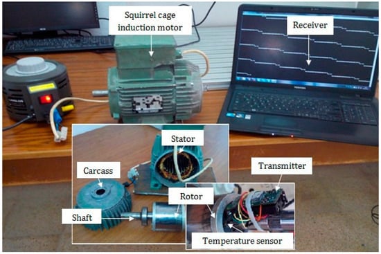
Figure 6.
RN171 antenna mounted inside the electrical machine.
The propagation factor within the electrical machine was 0.3 × 10⁻⁵, closely matching the simulated values. The two antennas were arranged similarly to previous simulations, approximating the maximum free-space over-ground propagation factor. Despite the antennas not being optimized for their surroundings, the power transfer efficiency was higher than theoretical predictions for two comparable antennas in a free-space scenario.
Our research focused on the effect of antenna positioning, specifically using the RN-171 transmitter, on the computed propagation factor. Interestingly, our analysis showed a significant decrease in the propagation factor when the antenna was placed on the machine compared to its performance in free space. This reduction aligns with theoretical expectations, as obstructions within the electrical machine significantly impact electromagnetic wave propagation.
The introduction of electrical components adds complexity and leads to signal attenuation. A major factor in this is interference from electrical noise, which greatly impairs wave propagation within the machine.
These observations highlight the complex interaction between the machine’s electromagnetic environment and wave behavior. This insight provides important considerations for future applications and improvements in industrial settings.
Table 3 presents an analysis of monopole antennas versus other types of antennas based on five different research works. This comparison includes evaluation parameters such as radiation patterns, gain, bandwidth, efficiency, size, ease of integration, and propagation factors. The aim is to highlight the performance characteristics and practical benefits of monopole antennas in various communication scenarios.
Table 3.
Comparative study table.
Monopole antennas offer advantages in terms of omnidirectional coverage, compact size, ease of integration, and consistent performance across varied environments. They are suitable for applications requiring uniform coverage and reliable performance in different orientations and settings. While other antennas like dipole, patch, loop, helical, and YagiUda antennas provide specific benefits in terms of gain, bandwidth, and directivity, the practical benefits of monopole antennas make them a preferred choice for many modern wireless communication applications.
Therefore, the monopole antenna is widely recognized for its superior performance and a range of beneficial characteristics, making it a preferred choice in various applications, especially in electrical machinery. This antenna features a simple design with a single radiating element mounted vertically on a conductive ground plane, which simplifies construction, installation, and maintenance.
Among its key attributes is its omnidirectional radiation pattern in the horizontal plane, providing consistent and uniform signal coverage in all directions. This is crucial for applications requiring broad area coverage without significant signal degradation. Additionally, the monopole antenna is highly efficient and exhibits low return loss, enhancing its ability to effectively transmit and receive signals. Its compact size and cost-effectiveness further contribute to its widespread use in both commercial and industrial settings.
The preference for using this antenna in electric machines is supported by extensive simulation results obtained using the highfrequency structure simulator (HFSS). These simulations have demonstrated that the monopole antenna maintains stable and reliable performance under various conditions, a critical factor for the dynamic environments in which these machines operate. Furthermore, empirical data from experimental studies have validated these findings, including precise calculations of the propagation factor. This factor is essential as it measures how effectively the antenna propagates the signal through different media, ensuring optimal performance.
The propagation factor is particularly useful in telecommunications and complex systems like tire pressure monitoring systems (TPMS), where reliable signal transmission is paramount. In TPMS, for instance, the antenna’s ability to provide consistent signal coverage ensures accurate and timely transmission of tire pressure data, enhancing vehicle safety. Overall, the combination of robust simulation data and empirical results underscores the monopole antenna’s exceptional performance and suitability for modern electrical machinery and complex telecommunication systems, solidifying its role as a crucial component for efficient and reliable operation.
5. Conclusions
Our research aimed to evaluate how the physical structure of electric machines affects signal propagation. We proposed systems involving a stationary antenna mounted on a shaft which communicates wirelessly with an external receiver. These systems are designed to operate optimally under open-space transmission conditions, highlighting the critical need for reliable sensor communication within electrical machines.
Ensuring reliable sensor transmission and reception is a major challenge for rotor temperature monitoring system (RTMS) engineers. Typically, RTMS use a transmitting antenna embedded within a shaft which wirelessly connects to a receiver unit outside the machine. These systems are often designed for optimal performance in free-space conditions. This study introduces a metric called the propagation factor to assess the effectiveness of electromagnetic (EM) propagation, taking into account antenna efficiency and reflection losses. Simulations show that strategically placed and aligned RN-171 antenna can nearly achieve the theoretical peak in free-space propagation above a ground plane.
The electrical machine body significantly degrades the propagation factor, making it over 100 times worse than the ideal free-space benchmark. This highlights the need for antenna designs that do not prioritize free-space communication. Instead, a better strategy is to design antennas that use surface waves traveling along the electrical machine body.
To validate this potential, a simple experiment was conducted. Although this design may not be the best for any specific RTMS application, it clearly shows the importance of leveraging the electrical machine body to improve the efficiency of wireless RTMS communications.
A more effective approach would be to develop antennas that leverage wave transmission through machine components. Future work will involve conducting preliminary tests to confirm that such antennas can achieve a higher propagation factor, even in open-space conditions without obstructions. While this design may not be universally applicable, it underscores the potential benefits of integrating electrical machine components to enhance the efficiency of rotating temperature monitoring systems (RTMS).
Author Contributions
Methodology, S.B.B. and S.D.; Validation, S.B.B. and R.B.; Formal analysis, J.D.; Resources, J.D.; Writing—original draft, S.B.B.; Writing—review & editing, A.H.; Supervision, R.B.; Project administration, R.B., T.-H.V. and J.D. All authors have read and agreed to the published version of the manuscript.
Funding
This research received no external funding.
Data Availability Statement
Data is contained within the article.
Acknowledgments
We would like to thank the Deanship of Scientific Research at Shaqra University for supporting this work.
Conflicts of Interest
The authors declare no conflict of interest.
References
- Tavner, P.J. Review of condition monitoring of rotating electrical machines. IET Electr. Power Appl. 2008, 2, 215–247. [Google Scholar] [CrossRef]
- Xiang, D.; Ran, L.; Tavner, P.; Yang, S.; Bryant, A.; Mawby, P. Condition monitoring power module solder fatigue using inverter harmonic identification. IEEE Trans. Power Electron. 2012, 27, 235–247. [Google Scholar] [CrossRef]
- Dorell, D.G. Detection of Rotor Eccentricity in Wound Rotor Induction Machines Using Pole-Specific Search Coils. IEEE Trans. Magn. 2015, 51, 1–4. [Google Scholar] [CrossRef]
- Ceban, A. Methode Globale de Diagnostic des Machines Electriques. Ph.D. Thesis, Universite d’Artois, Arras, France, 2012. [Google Scholar]
- Mahulkar, V.; McKay, S.; Adams, D.; Chaturvedi, A. System-of-systems modeling and simulation of a ship environment with wireless and intelligent maintenance technologies. IEEE Trans. Syst. Man Cybern. Part A Syst. Hum. 2009, 39, 1255–1270. [Google Scholar] [CrossRef]
- Larios, D.F.; Barbancho, J.; Rodriguez, G.; Sevillano, J.L.; Molina, F.J.; Leon, C. Energy efficient wireless sensor network communications based on computational intelligent data fusion for environmental monitoring. IET Commun. 2012, 6, 2189–2197. [Google Scholar] [CrossRef]
- Brahim, S.B.; Bouallegue, R.; David, J.; Vuong, T.H. Path Loss Characteristics for Wireless Communication System in Rotating Electrical Machine. In Proceedings of the 2016 30th International Conference on Advanced Information Networking and Applications Workshops (WAINA), Crans-Montana, Switzerland, 23–25 March 2016; pp. 450–454. [Google Scholar] [CrossRef]
- Brahim, S.B.; Bouallegue, R.; David, J.; Vuong, T.H. Wireless communication to monitor the rotating electrical machines. In Proceedings of the 2015 23rd International Conference on Software, Telecommunications and Computer Networks (SoftCOM), Split, Croatia, 16–18 September 2015; pp. 269–273. [Google Scholar] [CrossRef]
- Giesbrecht, M.; de Carvalho Ferreira, G.T.; da Silva, R.R.; Milfont, L.D. Electric Machine Design and Fault Diagnosis for Electric Aircraft Propulsion in the Context of the Engineering Research Center for the Aerial Mobility of the Future. In Proceedings of the 2023 IEEE Workshop on Power Electronics for Aerospace Applications (PEASA), Nottingham, UK, 18–19 July 2023; pp. 1–5. [Google Scholar] [CrossRef]
- Zaabi, W.; Bensalem, Y.; Trabelsi, H. Fault analysis of induction machine using finite element method (FEM). In Proceedings of the 2014 15th International Conference on Sciences and Techniques of Automatic Control and Computer Engineering (STA), Hammamet, Tunisia, 21–23 December 2014; pp. 388–393. [Google Scholar] [CrossRef]
- Henao, H.; Capolino, G.A.; Fernandez-Cabanas, M.; Filippetti, F.; Bruzzese, C.; Strangas, E.; Pusca, R.; Estima, J.; Riera-Guasp, M.; Hedayati-Kia, S. Trends in Fault Diagnosis for Electrical Machines: A Review of Diagnostic Techniques. IEEE Ind. Electron. Mag. 2014, 8, 31–42. [Google Scholar] [CrossRef]
- Aileen, C.J.; Nagarajan, S.; Reddy, S.R. Detection of broken bars in three phase squirrel cage induction motor using finite element method. In Proceedings of the 2011 International Conference on Emerging Trends in Electrical and Computer Technology, Nagercoil, India, 23–24 March 2011; pp. 249–254. [Google Scholar] [CrossRef]
- Aldea, C.L.; Bocu, R.; Solca, R.N. Real-Time Monitoring and Management of Hardware and Software Resources in Heterogeneous Computer Networks through an Integrated System Architecture. Symmetry 2023, 15, 1134. [Google Scholar] [CrossRef]
- Brahim, S.B.; Bouallegue, R.; David, J.; Vuong, T.-H. Electromagnetic Wave Propagation characteristics of rotating antenna in electrical machine. In Proceedings of the 11th International Conference on Wireless Communications, Networking and Mobile Computing (WiCOM 2015), Shanghai, China, 21–23 September 2015; pp. 1–6. [Google Scholar] [CrossRef]
- Ben Brahim, S.; Bouallegue, R.; David, J.; Vuong, T.H.; David, M. A Wireless On-line Temperature Monitoring System for Rotating Electrical Machine. Wirel. Pers. Commun. 2017, 95, 979–999. [Google Scholar] [CrossRef]
- Sunil, M.P.; Devaraj Verma, C. The Smart Development of Multichip Communication Systems with The Help of Short Transmission Nodes. In Proceedings of the 2023 International Conference on Distributed Computing and Electrical Circuits and Electronics (ICDCECE), Ballar, India, 29–30 April 2023; pp. 1–6. [Google Scholar] [CrossRef]
- Zeng, H.; Hubing, T.H. The Effect of the Vehicle Body on EM Propagation in Tire Pressure Monitoring Systems. IEEE Trans. Antennas Propag. 2012, 60, 3941–3949. [Google Scholar] [CrossRef]
- Prist, M.; Monteriù, A.; Freddi, A.; Cicconi, P.; Giuggioloni, F.; Caizer, E.; Verdini, C.; Longhi, S. Online Fault Detection: A Smart Approach for Industry 4.0. In Proceedings of the 2020 IEEE International Workshop on Metrology for Industry 4.0 & IoT, Roma, Italy, 3–5 June 2020; pp. 167–171. [Google Scholar] [CrossRef]
- Du, C.; Peng, Z.; Ren, Y.; Zhou, A.; Ma, Y.; Chen, J.; Deng, T. Advanced rotor temperature estimation of permanent magnet synchronous machines for electric vehicles. Adv. Mech. Eng. 2020, 12, 1687814020918742. [Google Scholar] [CrossRef]
- Zhu, Y.; Lu, Y.; Sun, F.; Qian, F.; Chen, W.; Chen, H. Study on Stability Test Method of Aeroelastic Machinery of Bearingless Rotorcraft. In Proceedings of the 2021 IEEE International Conference on Electrical Engineering and Mechatronics Technology (ICEEMT), Qingdao, China, 2–4 July 2021; pp. 351–356. [Google Scholar] [CrossRef]
- Maki, N.; Izumi, M.; Numano, M.; Aizawa, K.; Okumura, K.; Iwata, K. Design study of high-temperature superconducting motors for ship propulsion systems. In Proceedings of the 2007 International Conference on Electrical Machines and Systems (ICEMS), Seoul, Republic of Korea, 8–11 October 2007; pp. 1523–1527. [Google Scholar] [CrossRef]
- Rottach, M.; Gerada, C.; Hamiti, T.; Wheeler, P.W. Fault-tolerant electrical machine design within a Rotorcraft Actuation Drive System optimization. In Proceedings of the 6th IET International Conference on Power Electronics, Machines and Drives (PEMD 2012), Bristol, UK, 27–29 March 2012; pp. 1–6. [Google Scholar] [CrossRef]
- Liu, Y.; Ai, Z.; Liu, G.; Jia, Y. An Integrated Shark-Fin Antenna for MIMO-LTE, FM, and GPS Applications. IEEE Antennas Wirel. Propag. Lett. 2019, 18, 1666–1670. [Google Scholar] [CrossRef]
- Patel, D.; Maiti, C.; Muthuswamy, S. Real-Time Performance Monitoring of a CNC Milling Machine using ROS 2 and AWS IoT Towards Industry 4.0. In Proceedings of the IEEE EUROCON 2023—20th International Conference on Smart Technologies, Torino, Italy, 6–8 July 2023; pp. 776–781. [Google Scholar] [CrossRef]
- Abdallah, N.H.; Brahim, R.; Bouslimani, Y.; Ghribi, M.; Kaddouri, A. IoT device for Athlete’s movements recognition using inertial measurement unit (IMU). In Proceedings of the 2021 IEEE International Conference on Industry 4.0, Artificial Intelligence, and Communications Technology (IAICT), Bandung, Indonesia, 27–28 July 2021; pp. 109–114. [Google Scholar] [CrossRef]
- Vafiadis, N.V.; Taefi, T.T. Differentiating Blockchain Technology to optimize the Processes Quality in Industry 4.0. In Proceedings of the 2019 IEEE 5th World Forum on Internet of Things (WF-IoT), Limerick, Ireland, 15–18 April 2019; pp. 864–869. [Google Scholar] [CrossRef]
- Bartolomeu, P.C.; Vieira, E.; Hosseini, S.M.; Ferreira, J. Self-Sovereign Identity: Use-cases, Technologies, and Challenges for Industrial IoT. In Proceedings of the 2019 24th IEEE International Conference on Emerging Technologies and Factory Automation (ETFA), Zaragoza, Spain, 10–13 September 2019; pp. 1173–1180. [Google Scholar] [CrossRef]
- He, S.; Xie, J. A Novel Compact Printed Antenna Used in TPMS or Other Complex and Variable Environments. IEEE Trans. Antennas Propag. 2008, 56, 24–30. [Google Scholar] [CrossRef]
- Tulicki, J.; Weinreb, K.; Sułowicz, M. The possibility of distinguishing rotor cage bar faults in double squirrel cage induction motors on the basis of the stator current signal. In Proceedings of the 2017 International Symposium on Electrical Machines (SME), Naleczow, Poland, 18–21 June 2017; pp. 1–6. [Google Scholar] [CrossRef]
- Srinivasan, J.; Selvaraj, K.; Chitrarasu, J.; Resmi, R. Design and analysis of squirrel cage induction motor in short pitch and full pitch winding configurations using FEA. In Proceedings of the 2016 International Conference on Emerging Technological Trends (ICETT), Kollam, India, 21–22 October 2016; pp. 1–10. [Google Scholar] [CrossRef]
- KhakparvarYazdi, A.; Mostafavi, M.; Safaee, A.; Khajehoddin, S.A. An Alternative Method to Accurately Model Magnetic Components Using Ansys HFSS 3D. In Proceedings of the 2023 IEEE Applied Power Electronics Conference and Exposition (APEC), Orlando, FL, USA, 19–23 March 2023; pp. 1557–1564. [Google Scholar] [CrossRef]
- Zhang, H.; Sun, T.; Ren, W.; Yuan, C.; Chen, D. A Novel Dual-Band Printed Monopole Antenna with Modified SIR Loading. IEEE Access 2024, 12, 13893–13899. [Google Scholar] [CrossRef]
- Kim, S.; Nam, S. Wideband Vertically Polarized Endfire Metasurface Antenna Fed by Tightly Coupled Monopole Probe Array. IEEE Trans. Antennas Propag. 2024, 72, 2481–2489. [Google Scholar] [CrossRef]
- Dinh, N.Q.; Teranishi, T.; Michishita, N.; Yamada, Y.; Nakatani, K. Simple design equations of tap feeds for a very small normal-mode helical antenna. In Proceedings of the 2010 IEEE Antennas and Propagation Society International Symposium, Toronto, ON, Canada, 11–17 July 2010; pp. 1–4. [Google Scholar] [CrossRef]
- Song, H.J.; Hsu, H.P.; Wiese, R.; Talty, T. Modelling signal strength range of TPMS in automobiles. In Proceedings of the IEEE Antennas and Propagation Society Symposium, Monterey, CA, USA, 20–25 June 2004; Volume 3, pp. 3167–3170. [Google Scholar] [CrossRef]
- Arora, S.; Sharma, S.; Anand, R.; Shrivastva, G. Miniaturized Pentagon-Shaped Planar Monopole Antenna for Ultra-Wideband Applications. Prog. Electromagn. Res. C 2023, 133, 195–208. [Google Scholar] [CrossRef]
- Kumari, S.; Maurya, N.K.; Tripta Sarkar, A. Design and Parametric Study of Monopole Blade Antenna for UHF-Band Aerospace Applications. In Cognitive Computing and Cyber Physical Systems, Proceedings of the International Conference on Cognitive Computing and Cyber Physical Systems, IC4S 2023, Bhimavaram, India, 4–6 August 2023; Lecture Notes of the Institute for Computer Sciences, Social Informatics and Telecommunications Engineering; Pareek, P., Gupta, N., Reis, M.J.C.S., Eds.; Springer: Cham, Switzerland, 2024; Volume 537. [Google Scholar] [CrossRef]


Disclaimer/Publisher’s Note: The statements, opinions and data contained in all publications are solely those of the individual author(s) and contributor(s) and not of MDPI and/or the editor(s). MDPI and/or the editor(s) disclaim responsibility for any injury to people or property resulting from any ideas, methods, instructions or products referred to in the content. |
© 2024 by the authors. Licensee MDPI, Basel, Switzerland. This article is an open access article distributed under the terms and conditions of the Creative Commons Attribution (CC BY) license (https://creativecommons.org/licenses/by/4.0/).