Review

In-Depth Analysis of the Processing of Nomex Honeycomb Composites: Problems, Techniques and Perspectives

1
Centre de Recherche (CREHEIO) de L’Ecole des Hautes Etudes d’Ingénierie, Equipe de Production Intégrée, Oujda 60000, Morocco
2
Laboratoire d’Energétique et de Mécanique Théorique et Appliquée, Ecole des Mines de Nancy, Université de Lorraine, F-88100 Saint Dié Des Vosges, France
3
Department of Mathematics, Saveetha School of Engineering, SIMATS, Chennai 602105, Tamil Nadu, India
4
Laboratory of Energetics (LE), Faculty of Sciences, Abdelmalek Essaadi University, Tetouan 93000, Morocco
5
Laboratory of Mechanics and Scientific Calculation, National School of Applied Sciences, Oujda 60000, Morocco
*
Author to whom correspondence should be addressed.
Machines 2024, 12(8), 561; https://doi.org/10.3390/machines12080561
Submission received: 26 June 2024 / Revised: 4 August 2024 / Accepted: 9 August 2024 / Published: 15 August 2024
(This article belongs to the Section Material Processing Technology)

Abstract

:
Nomex honeycomb composites are widely recognized for their advanced structural applications in the aerospace, automotive and defense industries. These materials are distinguished by exceptional characteristics such as thin cell walls and a hexagonal structure, as well as layers made of phenolic resins and aramid fibers. However, complex machining and the maintenance of high quality at a large scale presents considerable challenges. This study provides a comprehensive review of the literature on the processing of Nomex composites, highlighting the design challenges related to processing technologies, the impact of conventional and ultrasonic processing methods, and the associated mechanical properties and microstructural topographies. Moreover, it reviews research advances in machining techniques, current challenges, and future perspectives, thereby providing valuable guidance to ensure the optimal cutting of Nomex honeycomb composite structures (NHCs).

1. Introduction

The appearance of modern honeycomb structures dates back to the late 1930s, and these cores, usually made using an expansion and corrugation process, are characterized by an arrangement of open cells with a hexagonal structure and extremely thin walls [1,2,3,4]. Recently, honeycomb cellular structures have garnered significant attention for use in high-performance sandwich panels, particularly in aerospace, automotive, and defense applications. This is due to their unique properties, including high strength, excellent stiffness-to-weight ratios, outstanding fatigue resistance, low density and corrosion resistance [5,6,7]. Honeycomb structures can be made from various materials, both metallic and non-metallic [8,9,10,11]. These materials include aluminum alloy [12,13,14], stainless steel [15,16], Nomex [17,18], kraft paper [19,20] and fiberglass [21,22]. Nomex honeycomb composites (NHC) are made from aramid paper impregnated with phenolic resins, giving their structure a Thin-Walled hexagonal configuration. The hexagonal cell core has double walls in the longitudinal (L) direction of the ribbon, while the width (W) and thickness (T) directions have single walls [23,24,25,26]. Typically, the thickness of cell walls in honeycomb structures varies between 0.05 and 0.13 mm, while the length of cell sides is usually between 2 and 5 mm [27,28,29]. Nomex honeycomb composites have attracted particular interest in various fields including aviation, aerospace, automotive (especially racing cars), high-speed trains and shipbuilding, as well as in sports and safety helmets, due to their advanced physical, mechanical and structural characteristics, such as light weight and excellent quality [30,31,32,33]. Common applications of Nomex honeycomb sandwich structures in aerospace components include floors, doors, wing flaps, fuselage fairings, control surfaces, overhead storage compartments, ceilings, sidewall panels, engine cowlings, spoilers, nacelles and Randoms [22,32,34,35]. Despite the common and necessary applications of honeycomb structures, the shaping of this type of structure nevertheless presents significant obstacles and challenges for engineers and researchers. These challenges include the complexity of manufacturing processes, the inherent brittleness of the materials, and the need to optimize processing parameters to achieve optimal mechanical and structural performance. Researchers must also overcome obstacles related to the understanding of surface formation mechanisms and the design of new cutting tools and techniques tailored to the specific requirements of honeycomb structures. The complexity of the manufacturing processes lies in the need to integrate advanced processing systems, such as ultrasonic straight blade tools and ultrasonic machines, to efficiently process honeycomb materials. These systems must be finely calibrated to ensure precise cutting and minimize structural damage. In addition, the brittleness of honeycomb materials, such as Nomex, requires delicate handling and specific processing conditions to avoid fractures and deformations. The optimization of processing parameters is crucial to maximize the performance of honeycomb structures. This involves an in-depth study of surface formation mechanisms, as well as rigorous testing to determine the best cutting conditions, such as speed, ultrasonic frequency and cutting angle. Researchers also need to develop theoretical and experimental models to predict the behavior of materials under different processing conditions. Furthermore, the design of new cutting tools and techniques is essential to meet the specific requirements of honeycomb structures. This includes the development of high-precision cutting tools, capable of working at microscopic scales and maintaining high surface quality. Innovation in cutting tool materials, as well as ultrasonic-assisted machining technologies, plays a key role in overcoming these challenges. Through continued research and technological development, it is possible to overcome current obstacles and advance the use of honeycomb structures in various industrial applications. Indeed, when machining composite and metallic honeycomb structures, it is essential to take into consideration mechanical studies of this type of structure. This includes extensive research on various aspects of material behavior, including compression, mechanical properties, numerical and finite element modeling, low velocity impacts and damage, elastic properties, bending, crushing, buckling, and elastic behavior [23,26,31,36,37,38,39,40,41,42,43,44,45,46,47,48,49,50,51,52,53,54,55,56,57,58]. Despite these advances, the processing of honeycomb structures continues to encounter several significant problems, including
  • Material fragility: Honeycomb structures, especially composite ones, are often fragile and susceptible to fracture or deformation under high mechanical stresses.
  • Optimization of processing parameters: It is crucial to determine the optimal machining conditions, such as cutting speed, ultrasonic frequency, and cutting angle, to minimize damage and maximize surface quality.
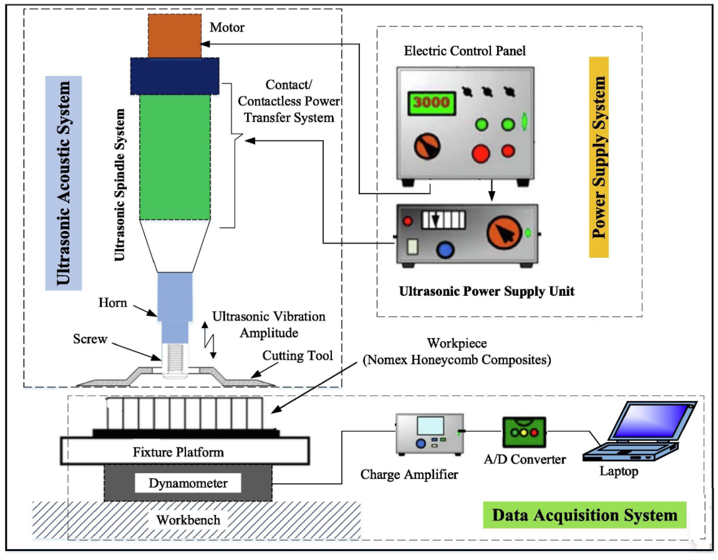
  • Complexity of manufacturing processes: The integration of advanced technologies, such as ultrasonic cutting tools, requires precise calibration and a thorough understanding of tool–material interactions.
  • Modeling and performance prediction: Developing theoretical and experimental models to predict the behavior of honeycomb structures under different machining conditions remains a major challenge.
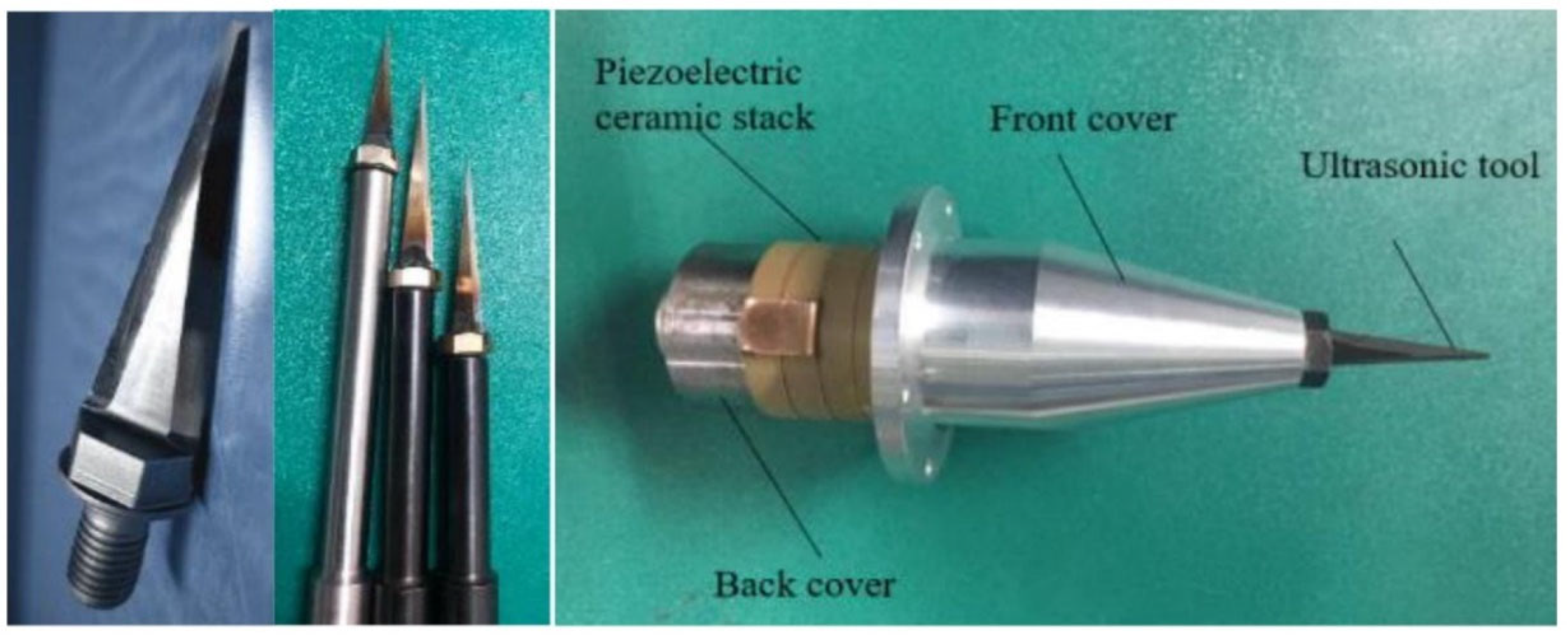
  • Designing innovative cutting tools: It is necessary to design high-precision cutting tools capable of working at microscopic scales while maintaining high surface quality.
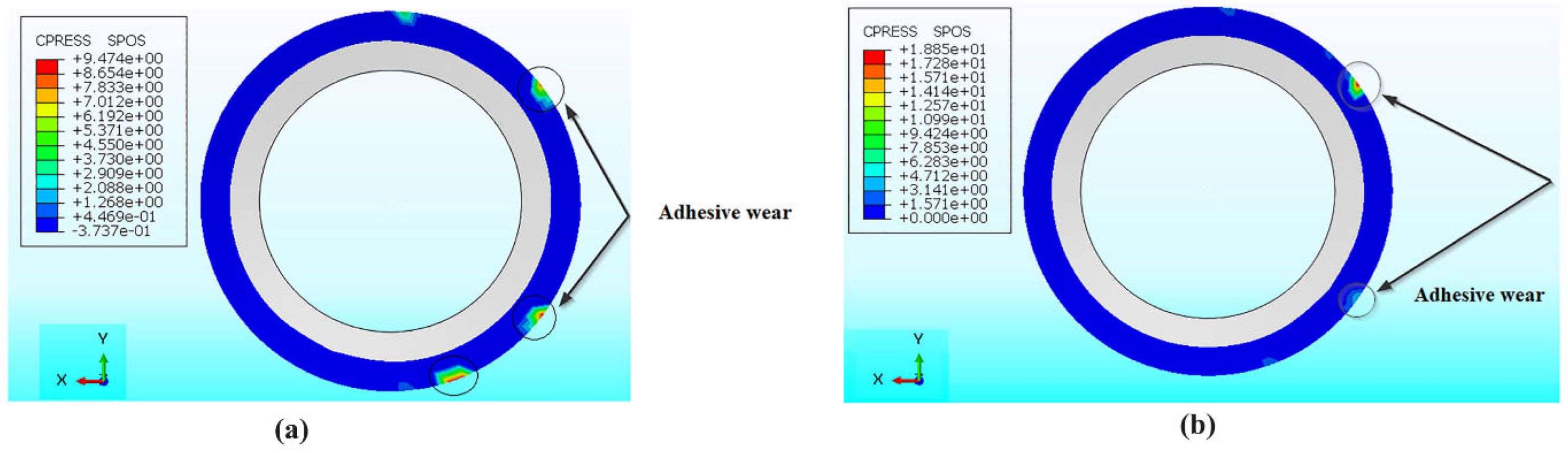
  • Tool Damage and Wear Management: Cutting tools used to machine honeycomb structures must be wear-resistant and capable of minimizing damage to the materials being machined.
By overcoming these challenges through continued research and technological development, it is possible to advance the use of honeycomb structures in various industrial applications.
The treatment of Nomex honeycomb composites structures currently incorporates a combination of conventional and innovative methods. However, due to the geometric complexity and special material properties of Nomex honeycomb composites, the development of specialized cutting equipment and tools is essential. Internationally, researchers [27,33,59] and equipment manufacturers have developed a diverse range of tools specifically tailored to the processing of these materials. The interaction between the cutting tool and the workpiece when using conventional cutting frequently leads to the occurrence of significant defects such as the delamination of aramid fibers, tears, burrs, cracks and the buckling of cell walls. To overcome the limitations of traditional methods, innovative technologies have been developed. Among these, ultrasonic vibration-assisted (UVA) processing techniques stand out for their increased efficiency, attributable to the intermittent interaction of the cutting tool with the workpiece, which reduces tool wear and decreases the required cutting force. This critical review focuses on a systematic analysis of the scientific literature and technological advances of recent decades, with particular emphasis on design issues and factors influencing the performance of treatment technologies. Furthermore, this analysis delves into the intricate nature of processing Nomex honeycomb composites, examining recent advancements in various processing technologies, cutting tools and machining processes. It also evaluates the impact of these technologies on the precision, properties and surface quality of Nomex honeycomb composites’ cores. Finally, studies on fixation techniques are presented, followed by a discussion on current challenges and future research avenues regarding processing technologies of Nomex honeycomb composite structures.

2. Conventional Methods of Processing Nomex Honeycomb Composites (NHC)

2.1. Specific Machining Processes for Honeycomb Structures

Given the alveolar structure of honeycomb, several specific machining processes have been developed by manufacturers in order to facilitate machining and improve the final quality of the machined surfaces. These methods were initiated in the 1950s and 1960s to overcome the challenges posed by the alveolar structure. The first method developed consisted of filling the cells with a third-party material, thus making the structure continuous and limiting the creation of burrs when machining honeycombs in metallic materials. Some works have proposed to fill these cavities with frozen water (Figure 1a) [60]. The solidified liquid will hold the honeycomb in place during machining and prevent significant deflections of the walls. This method also makes it easier to hold the honeycomb block on the machine during machining [61]. It is used for honeycombs that do not pose problems with water contact, such as those made of aluminum, unlike honeycombs made of Nomex. Wang [62] suggested utilizing a freeze-fixing technique in a cryogenic setting to examine the milling machining effects on an aluminum honeycomb core. The experiments showed that this method could enhance the holding force and fixation strength, achieving values up to 287 N and 19.1 kPa, respectively. In this regard, Jaafar et al. [63] developed a numerical model for high-speed conventional milling, aiming to improve the milling efficiency of Nomex honeycomb structures. His study examined the challenges encountered when machining Nomex honeycomb structures, as well as the impact of processing parameters on cell wall structure and surface quality. In this context, Qinglong et al. [64] performed an experimental study to investigate the processing defects, formation mechanisms, and cutting processes of honeycomb core cell walls during the milling of aluminum cores. Their research aimed to understand the intricacies of these phenomena to improve milling techniques.
Figure 1. (a) Solidification with frozen water [61]; (b) partial solidification with frozen water [65]; (c) solidification with liquid nitrogen [66].
Machines 12 00561 g001
In this context, due to the ability of Nomex to absorb water, the previous method is not applicable to this type of honeycomb. Thus, another procedure was developed, consisting of filling the cells of the structure with a resin that solidifies when cold, allowing the honeycomb to be kept in a rigid shape without deforming during machining. After machining, it is sufficient to expose the structure to room temperature to remove the resin which covers the honeycomb walls [67]. To address the same problem and to improve the machining rate, some manufacturers have used expanded foam introduced into the cells of the honeycomb. This allows the feed rate to be increased during machining and for machining to be carried out with severe cutting angles in the case of honeycombs with thin thicknesses, [68]. Another technique is to deform the honeycomb, taking advantage of its flexibility, in a mold with an imprint of the desired geometric shape. Subsequently, and before the machining operation, the shape is frozen using frozen water (Figure 1b) or liquid nitrogen (Figure 1c) to maintain the desired shape of the structure during machining [65,66]. None of these methods are suitable for industrial practices. Implementation constraints are a barrier to their widespread use. The conventional processing of Nomex honeycomb composite structures predominantly utilizes computer numerical control (CNC) machine tools, particularly bridge-type multi-axis gantry CNC milling machines [69], alongside 3-axis and 5-axis CNC machining centers [70]. In fact, large parts are precisely machined using bridge-type multi-axis gantry machine tools, while smaller elements of Nomex honeycomb composite structure are ideally machined using 3- or 5-axis machining centers. In a commercial setting, the conventional tool used for machining these composites consists of a circular cutter with a sharp blade at the front, a grinder with several helical teeth in the center to shred the chips, and a long shank to securely fasten it into the machine spindle. The cutting process involves the rotation of the tool along the spindle axis, combined with feed motion along the X-axis or Y-axis. The essential geometric characteristics of the conventional milling tool are illustrated in Figure 2b [71].

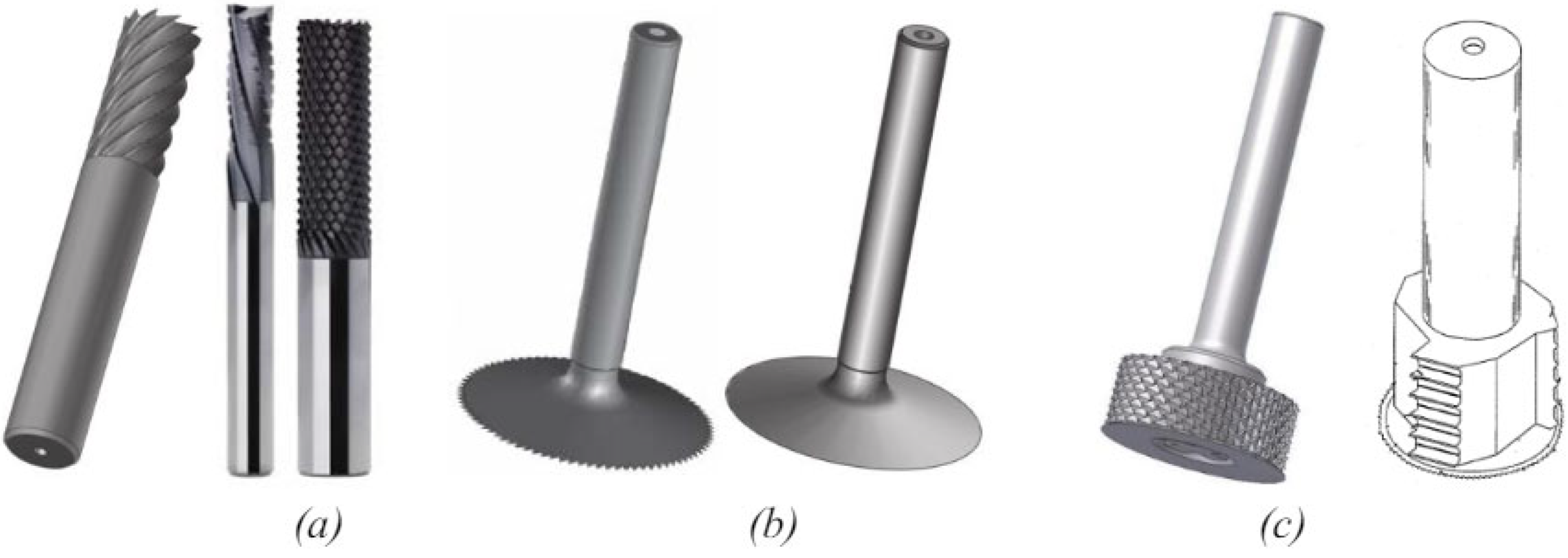
2.2. Diversity of Tools for Machining Honeycomb Structures

Various vendors offer a range of distinct tools, each distinguished by an almost unique geometry and design. This diversity arises from the multiple machining operations, the varied materials used in the manufacture of honeycombs, and the complex configurations encountered. Figure 3 illustrates the main categories of tools used in machining honeycomb materials, each defined by its particular geometries [72,73,74,75].
Figure 3. The tools used for machining honeycombs are grouped as follows: (a) solid tool [74,76]; (b) valve tool [74]; (c) combined tool [74,75].
Machines 12 00561 g003
Generally, three types of tools are commonly available: solid tools, valve tools, and combination tools. Solid tools have a similarity to trimming tools and reamers, featuring cutting helices that may include chip breakers in some cases. There are also tools in the form of smooth or toothed circular valves. These tools are used to cut the walls of honeycombs. The third configuration is a combination of the two previous designs. The combination tool is broken down into two essential parts: the tool body, which resembles the monobloc tools with chip breakers on the helices, and a circular blade which can contain teeth. Each of these components is characterized by several geometric properties in order to improve the machining of honeycomb materials. The circular blade features a sharpened edge to cut through material cleanly. The honeycomb cutting tool body does not just allow chip evacuation or material removal, but provides a shredding operation for the honeycomb walls previously cut by the blade [77,78].

2.3. Optimizing Machining Conditions for Improved Surface Quality

The main problem with this type of machining is associated with the quality of the surface obtained. Nasedkin et al. [79] machined aramid paper, a constituent of Nomex honeycomb, with an abrasive diamond tool and with a CO2 laser. Figure 4 shows the two surfaces obtained after machining. Uncut aramid fibers can be observed on the surface machined by the diamond tool; on the other hand, a clean surface is generated by laser machining. These machining defects affect the behavior of the aramid paper, with a decrease in compressive strength from 245 MPa to 196 MPa, and the uncut fibers induce cracks in the composite material, which facilitates its damage.
The composition of the walls of Nomex, defined by aramid fibers and phenolic resin, makes its machining comparable to that of composite structures. The machining of composites presents different shaping defects, distinct from those observed during the machining of metals due to the constituents of the composite materials (fibers and resin). The different types of damage induced by machining are
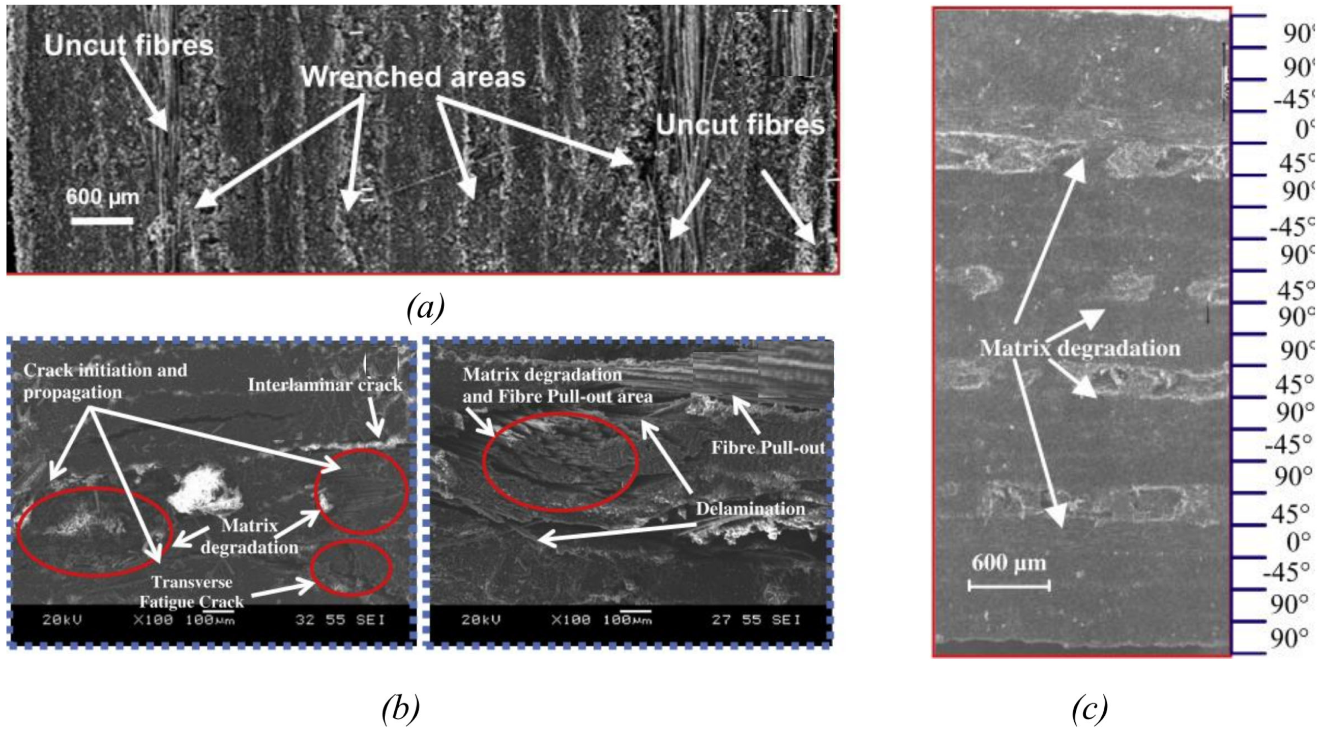
  • Thermal: burning of the matrix, etc.
  • Chemical: destruction of the fiber/matrix bonds, water uptake of the matrix.
  • Mechanical: tearing of fibers, delamination, cracking of the material.
Thermal damage is caused by friction between the tool and the material. In the case of drilling, thermal damage is intensified by the friction of the drill bit rim with the hole wall, combined with too high a cutting speed. Thermal damage results in local elimination of the matrix and exposure of the fibers. This is a phenomenon that is easily controlled by good control of the tool rotation speed. Chemical damage is mainly observed during lubrication-assisted machining; it depends on the rate of water uptake of the material and the time it is kept under high humidity. This results in a fiber/matrix decohesion that can generate cracks or delamination over time. Thus, dry machining or machining under micro-lubrication helps avoid this type of damage. Mechanical damage results in the appearance of defects, the most problematic of which are delamination and wall tearing. Depending on their size and frequency, these residual damages have the consequence of lowering the mechanical characteristics of the composite material, and particularly the breaking stress and the fatigue endurance limit. They are systematically repaired, and as a result lead to additional manufacturing costs. Composite materials are generally considered brittle materials because of their compositions. This behavior differentiates the damage and machining defects observed on this type of material from those of metals. Machining defects can be classified according to their location and the affected component. For defects located on the machined surface, damage is limited to uncut fibers, material tearing, and thermal degradation of the resin [80,81,82,83,84,85] (see Figure 5). These defects depend mainly on the cutting conditions used. Low cutting speeds of the tool promote the appearance of uncut fibers and the tearing of the material. Krapt et al. [86] found that increasing the rotational speed from 2500 rpm to 3000 rpm when milling CFRP allows machining without uncut fibers and gives a cleaner surface finish.
Figure 5. SEM micrographs showing machining defects of composites: (a) tear-out zone and uncut fibers during CFRP cutting [83]; (b) inter-ply delamination, initiation and propagation of cracks in CFRP during drilling [84]; (c) thermal degradation of resin during trimming [87].
Machines 12 00561 g005
Comparing the uncut fiber defect generated during the machining of Nomex honeycomb (Figure 4) and that of CFRP composite materials (Figure 5), it is clear that the length of uncut fibers is different; the uncut fibers in the case of Nomex machining are larger in size. This is explained by the difficulty of cutting aramid fibers because, unlike other fibers (carbon, glass), they are not fragile or brittle [78]. The surface quality of honeycombs is of primary importance for their use in sandwich structures. The machined surface is in direct contact with the sandwich skins. Poor assembly of the sandwich material affects its peel strength, so the assembly is carried out by an adhesive strip connecting the machined surface of the honeycomb to the skin. Khan [88] investigated the effect of honeycomb surface quality on the behavior of the sandwich structure. Three different surface qualities were studied. The first represents poor quality with uncut fibers, leading to a pronounced imbalance of the meniscus. These fibers hinder the flow of adhesive as well as the formation of the meniscus (Figure 6a). These fibers cause impurities in the resin, which present areas of weakness and generate cracks after the resin cures [51]. The second surface studied is obtained by ultrasonic machining and has a surface condition close to the first, with fewer uncut fibers. The decrease in uncut fiber density decreases meniscus imbalance (Figure 6b). Finally, a clean surface was used and a balanced meniscus was identified (Figure 6c). Uncut fibers represent the most harmful defect in the formation of the meniscus. They affect the strength of the sandwich structure through the appearance of cracks in the adhesive strip.
Researchers have examined various aspects of conventional computer numerical control machining of Nomex honeycomb structures. Many researchers have focused their efforts on the machining of honeycomb structure parts, analyzing conventional and unconventional manufacturing processes in detail. These studies involved a careful selection of different conventional cutting tools suitable for machining components made from materials such as carbon-fiber-reinforced plastic and aramid-fiber-reinforced plastic [89,90,91,92]. Jaafar et al. [93] focused his research on the high-speed conventional milling of Nomex honeycomb composite structures, emphasizing the optimization of cutting conditions. In the same context, Figure 7 presents the experimental setup of conventional milling and its effects on the machined surface quality of Nomex honeycomb structures, depending on various machining parameters. To analyze the cutting force involved in this process, Qiu [62] developed a cutting force model and performed simulations under various machining conditions to predict the force exerted on a single cell wall. The results demonstrated that the entry angle plays a crucial role in the formation of these cutting defects. Notably, cutting forces including burrs and overcuts are mainly observed at entry angles of 80° and 170°. Additionally, increased cutting force is observed when the entry angle exceeds 75°.
Figure 7 illustrates that lower spindle speeds and feed rates resulted in a notable presence of uncut fibers and burrs, while enhancing the spindle speed from 2000 rpm to 23,000 rpm led to an enhancement in surface quality. When the feed rate is excessively high while the spindle speed is low, it leads to cell wall tears, an increase in uncut fibers and the formation of significant burrs. The experimental results highlight that the optimization of the processing parameters exerts a significant effect on the machined surface of the Nomex honeycomb composite structure. The work of Zarrouk et al. [94,95,96,97] represents a notable advance in the field of machining Nomex honeycomb composite structures. Using a 3D numerical model based on the finite element method developed by the commercial software ABAQUS/Explicit in its version 6.17., he successfully and accurately predicted the influence of cutting tool diameter on the components of cutting force and chip size. These predictions are essential to optimize the efficiency and accuracy of the machining operation (Figure 8 and Figure 9).
The results in Figure 8 indicate that the machining forces are closely related to the gap between the cutting tool elements. The increase in the diameter difference leads to an increase in the feed component Fx due to the accumulation of material on the tool face, resulting in increased resistance. The crushing component Fz increases steadily with the variation in the diameters, due to the strong contact between the tool and the honeycomb structure. As for the cutting component Fy, it varies non-linearly depending on the diameter difference, attributable to the restoring force of the Nomex paper walls, influencing chip formation. Thus, the management of this gap is crucial to improve the durability of the cutting tool and optimize the machining process.
The results in Figure 9 show that the chip size when milling Nomex honeycomb composite structures is strongly related to the gap between the cutting blade and the cutter. The chip formation process is divided into two stages: first, the blade cuts the thin walls, and then the cut walls are pushed back by the cutter. A small gap promotes the formation of small chips, while a large gap generates larger chips. Thus, the gap between the two elements of the cutting tool significantly influences the chip size. Large chips are undesirable because they lead to premature wear of the tool. Therefore, it is crucial to consider this deviation when milling Nomex honeycomb composite structures to optimize the machining process. In the same context, Zarrouk et al. investigated the influence of feed rate on the premature sticking wear of the cutting tool based on a numerical model for milling Nomex honeycomb structures. This analysis was carried out by comparing the results of the numerical model through a visual examination, as illustrated in Figure 10.
The results presented in Figure 10 clearly show that the bonding wear is closely related to the feed rates, such that the wear becomes more pronounced for high feed rates. Based on these results, the imperfections in the machining process have a substantial effect on the bond strength of the sandwich layers between the Nomex honeycomb composite core and the skin materials. Although widely used in the aerospace, defense and automotive industries, conventional processing technologies have limitations such as reduced processing efficiency, dust generation, high processing defects and high tool wear. On the other hand, alternative processing methods like ultrasonic vibration-assisted machining present benefits such as increased processing efficiency, diminished processing defects, minimized surface damage, reduced cutting force, decreased tool wear, and lowered processing expenses. Currently, researchers are increasingly interested in unconventional processing technologies, with the aim of overcoming the limitations associated with conventional methods. This study is grounded in an extensive review of the literature spanning recent decades, providing a succinct comparison between conventional processing methods and vibration-assisted techniques, with a particular focus on ultrasonic methods, for Nomex honeycomb structures.

3. Machining of Nomex Honeycomb Composite Structure Assisted by Ultrasonic Vibrations

The term “ultrasound” refers to a vibration wave whose frequency exceeds the upper frequency limit of the human ear, set at 20 kHz [98,99,100]. Ultrasonic vibration-assisted processing is distinguished by a discontinuous cutting action, energy concentration, and micro-vibrations at the tool edge. These characteristics play a role in diminishing the resistance generated by plastic deformation and material fracture. As a result, they allow the cutting temperature to be reduced, tool wear to be limited, the required cutting force to be reduced and the quality of the machined surface to be revealed [101,102]. Ultrasonic vibration-assisted processing is suitable for a wide range of materials, both conductive and non-conductive, that pose machinability challenges, such as ceramics, titanium alloys, glass and composites [103,104,105]. The origins of ultrasonic vibration-assisted machining trace back to 1927, when Wood and Loomis pioneered the use of extremely high frequency waves on a glass substrate, along with abrasives, to facilitate material removal from the glass component. In 1945, L. Balamuth filed the first patent on ultrasonic machining, demonstrating the impact of tools with a mixture of grains and the material removal process [98,102,106,107]. Although ultrasonic vibration-assisted machining improves surface quality, its productivity is often compromised due to the reduced material removal rate and some geometric imperfections [98,108]. To overcome these limitations, the rotary ultrasonic machining (RUM) technique has been developed. Rotary ultrasonic machining (RUM), pioneered by Percy Legge in 1964 at the United Kingdom Atomic Energy Authority (UKAEA), is an unconventional hybrid process deemed non-electrical, non-thermal and non-chemical [98,109,110], and for which several machine tool manufacturers have introduced specialized ultrasonic cutting machines and tools tailored for processing Nomex honeycomb composite structures. Prominent manufacturers employing ultrasonic technology include DMG MORI [111], American GFM [112], Tongtai Machine & Tool Co., Ltd. [113], MS Ultrasonic Technology Group [114], OptiPro Systems [115], CRENO [116], COMI Group [117], SONOTEC [118] and MAQ [119], while numerous researchers have investigated the integration of ultrasonic machining systems with diverse machine tools and their processing mechanisms for various materials. Among the various approaches, research has explored ultrasonic vibration-assisted electrochemical machining (UVA-ECM) processes [120,121,122,123,124,125,126,127,128,129,130,131,132,133,134,135,136,137,138,139,140,141,142,143,144,145,146] and ultrasonic, ultrasonic vibration-assisted turning (UVA-Turning) [147,148,149,150,151,152,153,154,155,156,157,158,159,160,161,162,163,164], as well as ultrasonic rotary machining [165,166,167,168,169,170,171,172,173,174,175,176,177]. Currently, the integration of ultrasonic vibration-assisted processing systems with robotic arms is a major research topic in the field of the ultrasonic machining of difficult-to-work materials, including Nomex honeycomb composite structures. Figure 11 showcases ultrasonic processing equipment tailored for the Nomex honeycomb composite core, including the integrated ultrasonic machining system (THU-850), the PaR LM series precision motion platform for bridge-type ultrasonic machining systems, and the robotic arm ultrasonic machining system.
Figure 11. Ultrasonic machining system for Nomex honeycomb composite structure [178]: (a) integrated configuration for rotary ultrasonic machining (THU-850); (b) robotic arm configuration for rotary ultrasonic machining (GEBE2-SONIMAT technology).
Machines 12 00561 g011
The essential elements of ultrasonic processing devices, combined with conventional blade and circular knife-cutting tools for milling carbon-fiber-reinforced composites materials, are shown in Figure 12.
Figure 12 provides an overview of the ultrasonic processing system specifically designed for the Nomex honeycomb composite core. Ultrasonic machining of these composites involves converting electrical energy into mechanical vibrations: the high-frequency electrical signals produced by the ultrasonic generator are transmitted to the ultrasonic transducer, which transforms them into mechanical vibrations at the ultrasonic resonance frequency. These vibrations are then amplified by a device called an “ultrasonic horn” before being transmitted to the cutting part of the cutting tool. Effective matching of the ultrasonic transducer, ultrasonic horn and ultrasonic cutting tools is essential to ensure the resonant frequencies and vibration amplitudes required for Nomex honeycomb composite structure processing. In ultrasonic vibration-assisted processing systems, the transducer and ultrasonic horn are pivotal components, known for their precision and intermittent contact between the cutting tool and the workpiece, making them favorable for machining Nomex honeycomb composite structures and minimizing surface defects. These systems are generally divided into two main categories: those using straight or triangular blades and those using circular knives. Straight or triangular blades are preferred for rough cutting operations and the rapid removal of large quantities of material, while circular knives are more suited to profiling and finishing Nomex honeycomb composite structures. Subsequent sections of this paper will meticulously examine cutting tool designs, processing system integration and processing mechanisms, along with experimental and numerical findings.

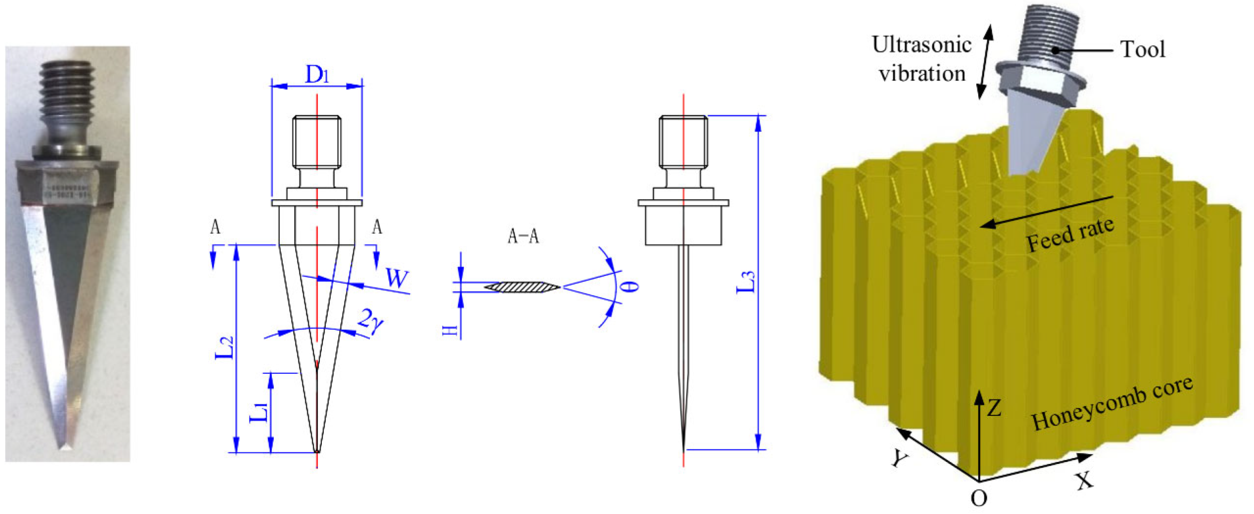
3.1. Ultrasonic-Assisted Straight-Blade Machining Systems

Research on the integration of processing systems with straight-blade tools and ultrasonic machine tools for Nomex honeycomb composite structures is still at a preliminary stage. It faces challenges such as the complexity of the integrated system, and in understanding the processing mechanism, studying the surface formation process, and optimizing the processing parameters. The key elements of these systems include an ultrasonic transducer, an ultrasonic horn, and an ultrasonic straight-blade cutting tool. The configuration of the cutting tools and the integrated structure of the system are shown in Figure 13. Furthermore, Hu et al. [179] focused on examining the specific challenges associated with the ultrasonic-assisted cutting of honeycomb structures (HCS) using triangular blades. This study also includes an analysis of orthogonal cutting as well as the influence of machining conditions on surface quality and the cutting forces generated. Xia et al. [59] analyzed the challenges associated with the structural design parameters of ultrasonic cutting discs used in the processing of Nomex honeycomb structures, as well as the fracture mechanics. This research also explored how tools’ geometric parameters influence energy density and stiffness.
The rise of industrial robots in manufacturing reflects a shift in production methods from mass production to mass customization. Robotic machining has the advantage of high flexibility compared to conventional machine tools, allowing robots to perform various machining processes by simply adjusting their tools or end effectors. This adaptability enhances the agility of companies and their ability to respond effectively to changing market demands. In addition, robots offer notable advantages, such as a large workspace, great freedom of movement and the ability to be deployed in mobile environments, all at a lower cost [180,181,182]. Robotic processing systems are generally structured in two ways: either with a serial manipulator or by attaching a spindle to the robot’s end effector. To meet the needs of a three-dimensional machining process, a spindle can be mounted on the fifth joint of the manipulator robot, thus avoiding the complexity associated with the sixth joint and reducing the impact of external forces on the process. This configuration is illustrated in Figure 14.
In today’s industry, the large-scale integration of robotic processing systems remains less widespread than that of specialized machine tools, due to several factors. First, robotic systems are more complex to implement. In addition, their accuracy is often lower than that of specialized machine tools, and they can have larger geometric errors. Finally, the high number of processing errors poses an additional challenge. These obstacles currently limit their large-scale adoption in industry. Recent studies have revealed two main categories of error in robotic processing systems. On the one hand, geometric errors often result from the misalignment of robot workstations and the deviations between the nominal and actual values of kinematic parameters. On the other hand, non-geometric errors are caused by environmental factors such as temperature, atmospheric pressure, humidity and dust pollution, as well as internal elements such as friction, backlash, limited controller bandwidth and low rigidity of the robot manipulator. It is important to note that the rigidity of industrial robots is typically about 50 times lower than that of dedicated conventional machine tools. The variations and errors observed in robotic machining systems are illustrated in Figure 15.

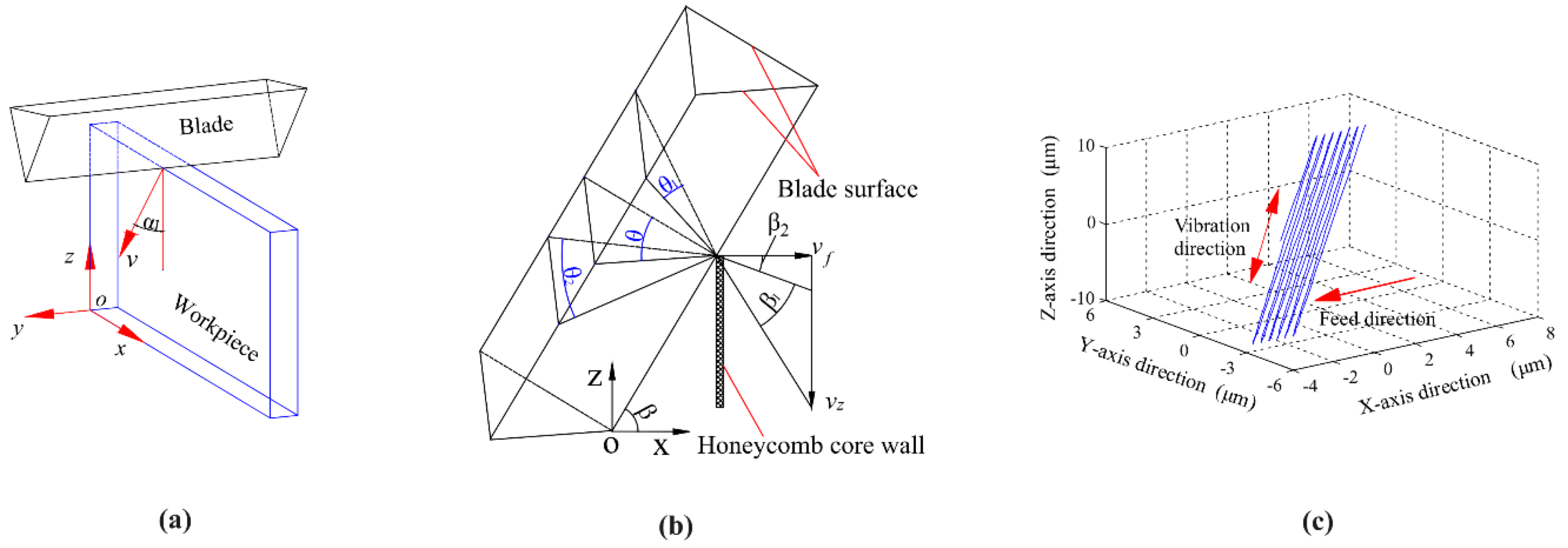
3.1.1. Analysis of the Characteristics of Straight Knife Processing on the Machinability of Nomex Honeycomb Composite Structures

The amplitude and resonance frequency of ultrasonic vibrations play a crucial role in processing systems using straight blades. When designing these tools, it is essential to select and optimize all parameters, considering these variables. An experimental study by Wang [183] investigated the impact of cutting conditions on surface quality and cutting force, revealing that the tool tilt angle and vibration amplitude influence these criteria. Meanwhile, in a complementary approach, Xiang [184] analyzed the surface defects resulting from the straight-knife cutting direction variations in conjunction with ultrasonic vibrations. In addition, Kang [185] developed a theoretical model to evaluate the cutting force during the straight-knife machining of the Nomex honeycomb composite core, highlighting the influence of processing parameters and tool design on the cutting force and surface quality. Cutting force is the stress exerted on the cutting edges of straight-blade cutting tools during the machining of Nomex honeycomb composite structures, representing the material removal resistance. Its analysis is crucial to validate and optimize the design parameters of ultrasonic straight-blade cutting tools, as well as the associated processing variables. This analysis is based on various methods such as mathematical modeling, finite element simulations and empirical experiments. The efficiency, cutting force, and surface quality of workpieces in ultrasonic straight-blade cutting systems are significantly impacted by their design parameters. Straight-blade cutting tools for Nomex honeycomb composite structures are typically developed based on the resonance principle, ensuring optimal performance. High-speed steel (HSS-W18Cr4V) is a common option for such cutting tools. Figure 16 illustrates the design features of the straight-blade cutting tool and the schematic of the machining process.
In the machining of honeycomb composites, ultrasonic straight-blade cutting tools are favored for various tasks, such as rough machining, cutting and edging. The V-shaped cutting method is often used for the initial processing of these materials. Ultrasonic conventional blade cutting tools make two successive passes on an identical trajectory to obtain a V-shaped surface, by transmitting ultrasonic vibrations through an acoustic spindle device to the tool’s axis of symmetry. This approach allows for efficient V-shaped rough processing of the honeycomb composites while ensuring optimum cutting quality. The process involves the synchronization of two movements: the programmed movement of the tool along its trajectory and the ultrasonic vibration along the central axis of the device. During ultrasonic processing, the straight-blade cutting tool comes into contact with the part irregularly, causing high-energy impacts on its surface. This induces shear, compression and tearing forces, leading to the formation of microcracks in the material. The sharp edges of straight-blade cutting tools facilitate burr-free and fiber-free cutting on the machined surface, as depicted in Figure 17, which illustrates the cutting process and the geometric correlations among tool angle, rake angle, cutting speed and the trajectory of the sharp cutting tool through ultrasonic longitudinal vibration-assisted cutting.
To fully comprehend the cutting mechanism associated with straight-blade cutting, it is crucial to examine the cutting tool displacement and speed, which are determining factors in the machining process of honeycomb composites with this technology. The displacement and velocity parameters of straight-blade cutting tools can be defined using various notations such as A for the ultrasonic longitudinal vibration amplitude, vf for the feed rate, β for the tilt angle, α for the defective angle, f for the ultrasonic vibration frequency, t for time and Sx, Sy, Sz, Sx, Sy and vz for the tool displacements and velocities along different axes. The relevant equations have been documented in the literature [179,184,186].
S x = A S i n 2 π f t · C o s β + v f · t S y = A S i n 2 π f t · S i n β ·   S i n α S z = A S i n 2 π f t · S i n β   ·   C o s α
By deriving Equation (1), the speed can be determined as follows:
v x = 2 π f A   C o s 2 π f t · C o s β + v f · v y = 2 π f A   C o s 2 π f t · S i n β   ·   S i n α v z = 2 π f A   C o s 2 π f t · S i n β   ·   C o s α
Referring to Equations (1) and (2), two cases are possible when processing honeycomb composites with a straight blade: continuous processing and discontinuous processing.
  • In the case of continuous processing, when the feed direction of the straight-blade cutting tool matches the speed direction vf during the entire cutting cycle, constant contact between the cutting tool and the workpiece is maintained during processing. In this situation, the feed rate equation can be formulated as follows:
v f   2 π f A   C o s β
  • In the case of discontinuous processing, when the straight-blade cutting tool moves rapidly in the opposite direction to vf during a specific period of the ultrasonic cycle, periodic contact between the cutting tool and the workpiece occurs. This case can be described as follows:
v f < 2 π f A   C o s β

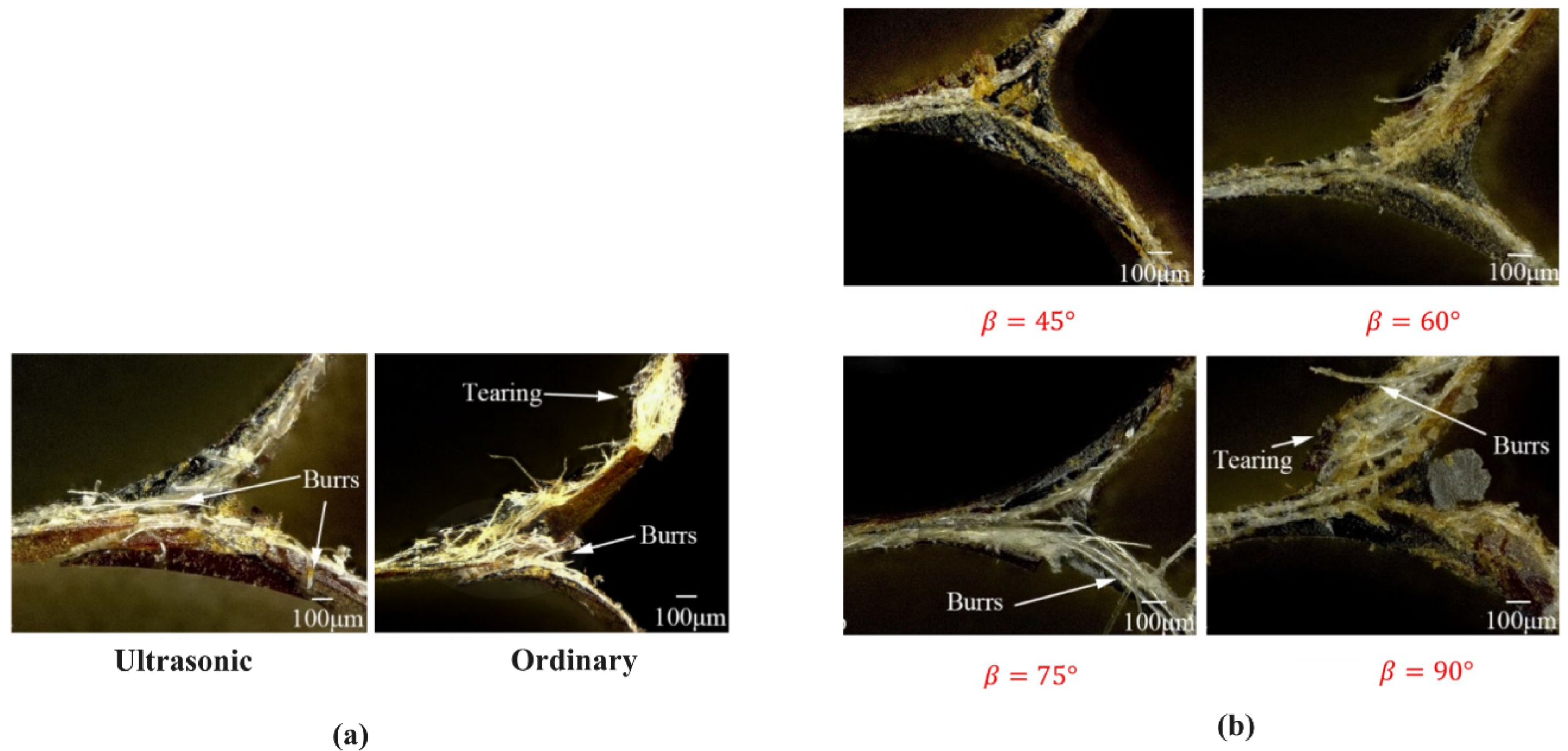
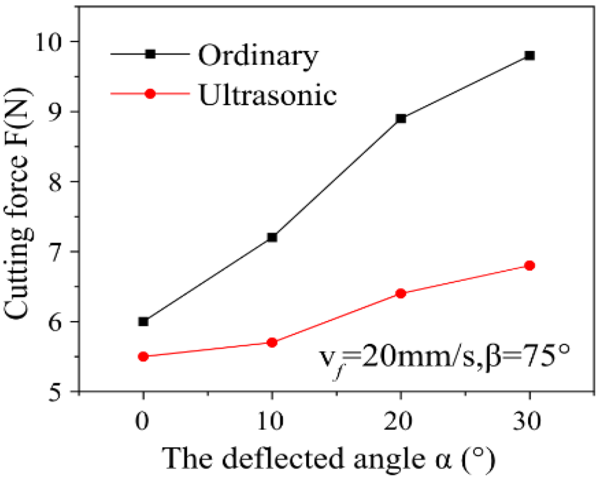
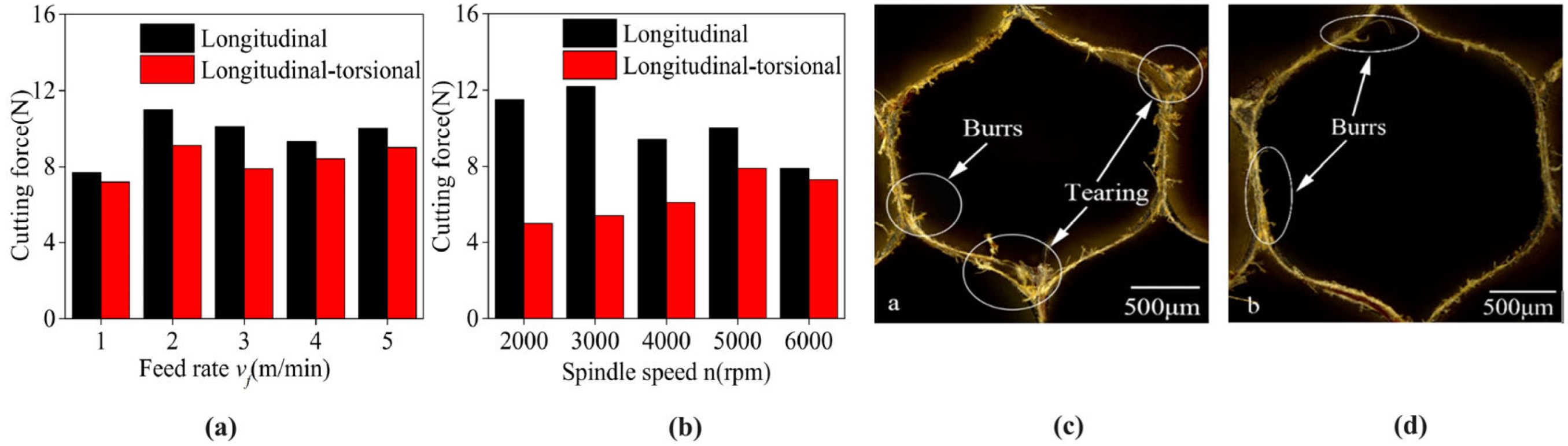
3.1.2. Impact of Straight Knife Treatment on the Nomex Honeycomb Structure: Machined Surface Quality and Cutting Force

The assessment of the influence of the design parameters of the straight knife processing system, including aspects such as tool thickness, tool tilt angle, tool length, and tool material, as well as processing variables such as ultrasonic longitudinal vibration amplitude, tool tilt angle, cutting depth and width and feed rate, on the cutting performance and machined surface quality, is commonly carried out using analytical approaches, finite element simulations and experimental tests. Usually, the practical organization for carrying out the experimental process of processing straight Nomex honeycomb composite blades with the assistance of ultrasonic longitudinal vibration includes several components, including an ultrasonic acoustic system, a multi-axis numerical control machine tool, a dynamometer for measuring cutting force, a data acquisition device, an ultrasonic generator, a power transfer mechanism and various necessary accessories. These components are presented in detail in Figure 18.
Figure 18 shows an ultrasonic-vibration-assisted machining setup, where the Nomex honeycomb composite core is fixed to the base of the fixture using double-sided tape and securely anchored to the machine table. A Kistler force gauge, positioned between the machine table and the workpiece, is used to measure the cutting force. During ultrasonic longitudinal vibration processing, the periodic interaction between the cutting tool and the workpiece generates impacts that promote the formation of microcracks in the material. The machining of Nomex honeycomb composites with straight or triangular blade cutting tools does not require any rotational motion. Furthermore, ultrasonic machining and conventional processes can be alternated simply by switching the ultrasonic power of the generator on or off, thus using the same experimental setup. In this context, the experimental results highlight that the ultrasonic longitudinal vibration-assisted processing produces a superior surface quality compared to the conventional process, under identical processing parameter conditions (Figure 19a). Furthermore, a gradual increase in the burr rate and tearing of the machined surface is observed with the increase in the inclination angle during the ultrasonic-vibration-assisted cutting of the Nomex honeycomb composite structure (Figure 19b). The study by Ma et al. [27] provided strong evidence for the effectiveness of ultrasonic processing in reducing cutting force and improving surface quality compared with conventional methods. In addition, the results of the mathematical model were consistent with the experimental data, thus strengthening the reliability of the approach used. So far, the literature on the processing of straight blades of Nomex honeycomb composite structures assisted by ultrasonic longitudinal vibration remains limited. A few works have addressed this topic from various angles, including cutting force models, finite element (FE) simulations, cutting tool design, processing parameter optimization, kinematic analyses and fracture mechanics theory [183,184,185,186,187,188,189,190,191].
In their study, Xiang et al. [184] observed a negative correlation between cutting force and both vibration amplitude and tool tilt angle. On the other hand, a positive correlation was noted between cutting force, deflection angle and feed rate. Ultrasonic cutting tests conducted by Xiang demonstrated that this technique reduces the cutting force compared to the traditional method (see Figure 20). Furthermore, Ma et al. [27] developed a mini ultrasonic cutting system and modeled it mathematically. Their in-depth analysis revealed that the use of ultrasound decreased the cutting force and improved the surface quality compared with conventional methods. The experimental results were found to be consistent with the predictions of the mathematical model, thus validating the effectiveness of the ultrasonic method.

3.2. Ultrasonic-Assisted Circular Slope Machining Systems

Systems equipped with circular knives are specifically designed to optimize surface quality and remove excess material from Nomex honeycomb composite structures. Compared to systems using straight blades, those equipped with circular knives introduce additional complexity due to the integration of rotary motion. These systems include essential elements such as an ultrasonic transducer, an ultrasonic horn, and a circular knife specially adapted for ultrasound. The geometric characteristics of circular cutters are crucial, as they directly influence the vibrations produced and the resonance frequency of the system. Figure 21a illustrates the geometrical parameters of these tools, while Figure 21b details the integrated configuration of the system with a circular cutter, highlighting the importance of these parameters in the design and operation of the system [189].
Material selection for cutting tools in ultrasonic vibration-assisted processing is critical to ensure maximum efficiency. This process, which uses high-frequency ultrasonic vibrations applied directly to the cutting tool, requires materials that are highly resistant to dynamic loading. Commonly selected materials include high-speed steel (HSS), alloy tool steel, cemented carbide, carbon tool steel and ceramics. Each material offers specific advantages and limitations. For example, ceramic, while very hard and wear-resistant, has low toughness, making it vulnerable to impact. Cemented carbide, on the other hand, offers high hardness but can be brittle when faced with sudden impacts. Carbon tool steels, while economical, offer lower abrasion resistance compared to other more specialized alloys. Alloy tool steels, on the other hand, are suitable for lower cutting speeds due to their good resistance to high temperatures. High-speed steel (HSS) is often the preferred choice for circular knife tools, due to its excellent toughness, stiffness, abrasion resistance, and impact resistance characteristics. This combination of properties makes HSS an ideal candidate to withstand the stresses imposed by high frequencies of ultrasonic vibrations [190].

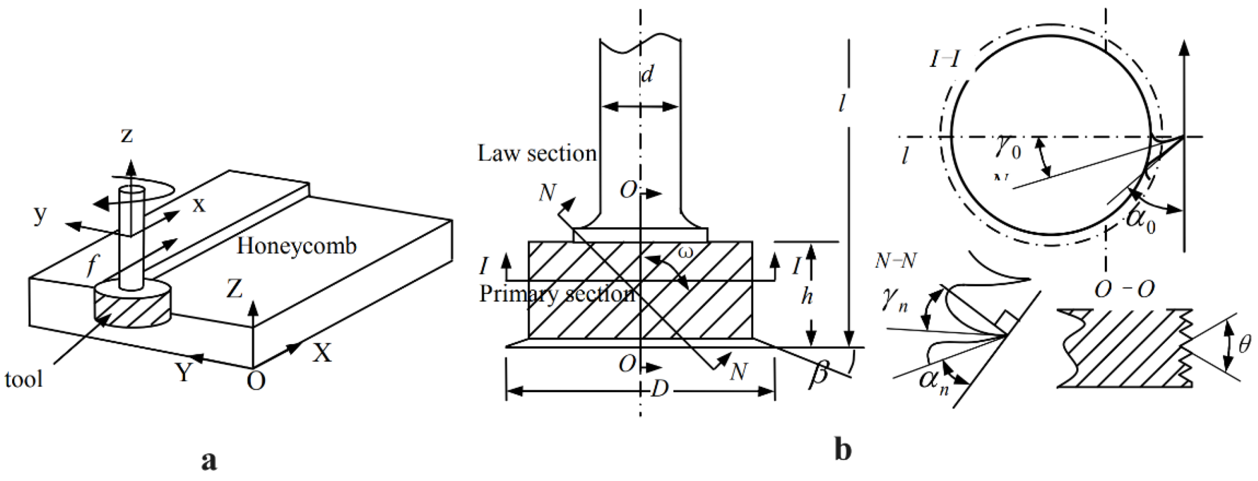
3.2.1. Analysis of the Characteristics of Circular Knife Processing on the Machinability of Nomex Honeycomb Structures

The study conducted by Xu et al. [190] focused on the analysis of the structure of a disc cutter. Its main objective was to determine the optimal parameters that influence the performance of the disc cutter, including its diameter (d), the cutting angle (θ) and the thickness of the disc (h) (Figure 22). To do this, a single-factor modal simulation was proposed, a method allowing us to understand the impact of each parameter in isolation on the dynamic properties of the disc, such as its natural vibration frequency and its response to mechanical stresses. Optimizing these parameters is of critical importance to maximize cutting efficiency while minimizing wear and harmful vibrations, contributing to the better durability and performance of the cutting system.
Figure 23 presents the results of the modal analysis for different tool parameters. As per Figure 23a, it was observed that when the diameter was kept constant, the resonance frequency was positively correlated with the increase in thickness. When the tool thickness varied from less than 1 mm to more than 1 mm, increasing by an average of 0.1 mm, the resonance frequencies increased by 1.7 kHz and 2.2 kHz, respectively. Furthermore, a decrease in the rake angle was associated with a steeper slope of the curve. Figure 23b reveals that at constant rake angle, the resonance frequency exhibits a negative correlation with increasing tool diameter. When the diameter is less than 30 mm, the frequency decreases by 3.2 kHz for each additional millimeter, while above 30 mm, the decrease is 0.37 kHz per additional millimeter. Additionally, increased tool thickness is associated with a steeper slope of the curve. Figure 23c reveals that at constant thickness, the resonance frequency shows a negative correlation with increasing rake angle, and this decreasing trend remains relatively stable with an increasing rake angle. Moreover, an average increase of 1° in rake angle is associated with a decrease in resonance frequency of 78 Hz, 33 Hz, and 11 Hz, respectively. Furthermore, as the diameter increases, the sensitivity of the rake angle to the change in resonance frequency decreases. In this context, Shahzad [191] conducted an extensive study on the processing technologies and mechanisms associated with Nomex honeycomb composites, emphasizing several key points. These points included the design challenges of ultrasonic circular knife-type cutting tools and the impact of the geometry of these tools on the resonance frequency, as well as finite element simulations of integrated ultrasonic circular knives and ultrasonic cutting tools. Ke [59] undertook an analysis of the many challenges related to fixture reliability, reduced machining efficiency and surface integrity of the Nomex honeycomb composite structure. With this in mind, he proposed a new assembly approach, based on magnetic principles and friction theory, to address these issues.

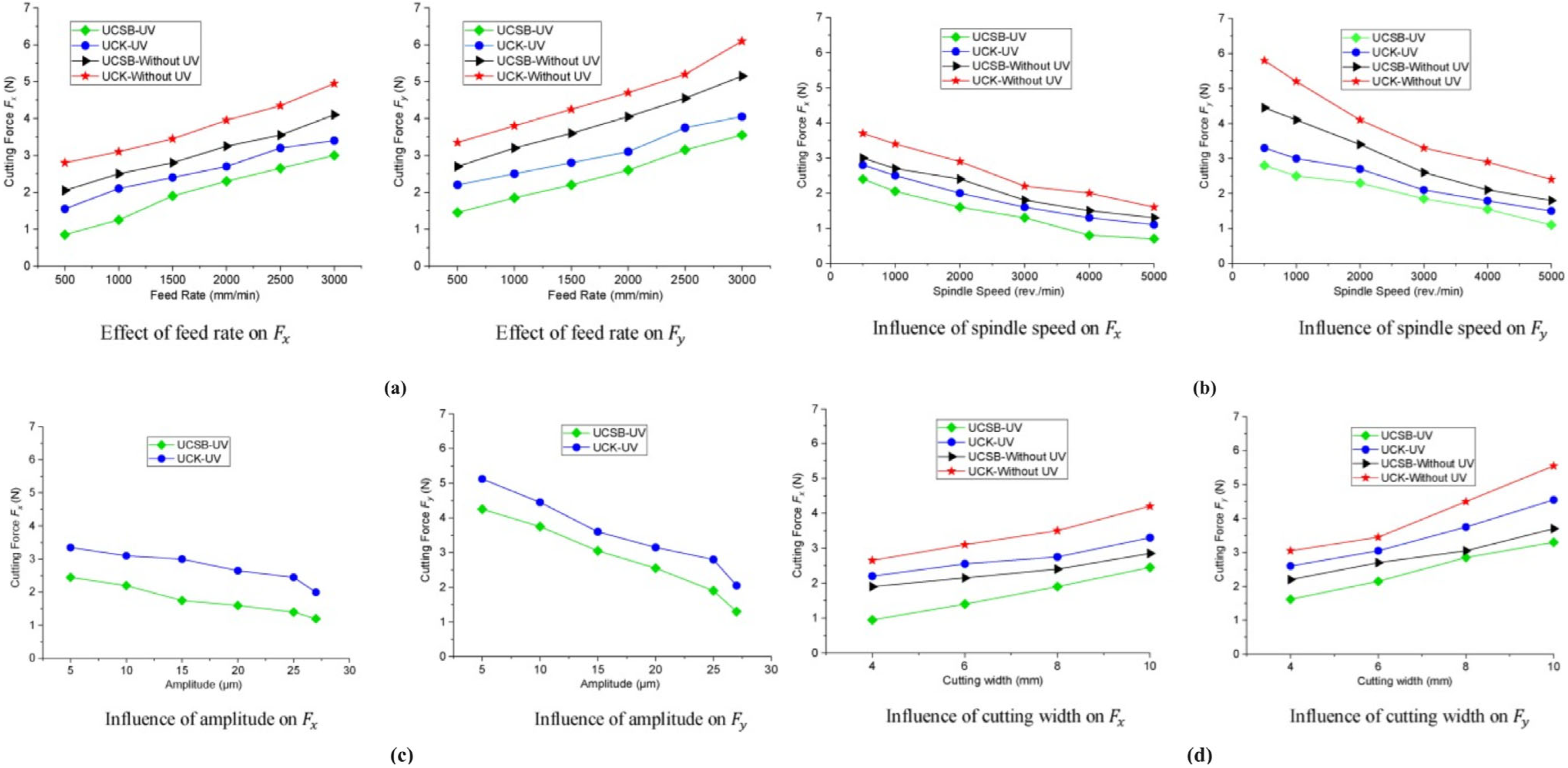
3.2.2. Impact of Straight Knife Treatment on Nomex Honeycomb Structure: Machined Surface and Cutting Force

Ultrasonic vibration-assisted machining equipment uses circular blades, classified into longitudinal and longitudinal–torsional ultrasonic vibration systems. The ultrasonic longitudinal vibration-assisted milling of Nomex honeycomb composite structures with a circular cutting tool involves three motions: longitudinal vibration along the spindle axis, spindle rotation and tool feed in the cutting direction. Thus, the treatment process involves the effect of ultrasonic vibrations on the workpiece at a determined vibration amplitude. This causes the short and fragile fibers of the Nomex honeycomb composite structure to break and generates microcracks on the surface of the substrate. In addition, the combination of the high-speed rotation of the ultrasonic vibration-assisted circular cutting tool and its feed produces a shearing action to cut the material and remove debris from the cutting area, thus ensuring a smooth surface and high finish quality. In contrast, when processing Nomex honeycomb composite structures using ultrasonic longitudinal–torsional vibration-assisted circular knife systems, an extra torsional motion is introduced compared to processing with simple longitudinal vibration. The cutting tools thus perform four separate motions concurrently. During the machining process, the circular cutting tool contacts the workpiece at the points of maximum amplitude, while no contact is established between the cutting tool and the workpiece during the rest of the vibration cycle. In addition, during the ultrasonic longitudinaltorsional vibration cutting process, the ultrasonic torsional vibration of the circular cutting tool alternates with its rotational motion, creating a saw-like cutting action on the cellular structure of the thin walls of the Nomex honeycomb composite structure. This saw-like cutting action, performed by the ultrasonic vibration-assisted circular cutting tool, improves process efficiency and promotes the fragmentation of Nomex fibers, which are both short and fragile, while allowing the removal of material from the part with improved surface quality. Due to the application of ultrasonic longitudinal and torsional vibrations, as well as the cellular nature of the Nomex honeycomb composite structure, a precise gap is maintained between the cutting tool and the part through the machining cycle. This setup aids in decreasing frictional forces between the machined surface and the cutting tool, thereby reducing defects like tearing, delamination of aramid fibers, dust generation and the buckling of cell walls. The schematics describing the processing mechanism involving the ultrasonic vibration-assisted circular knife tool of Nomex honeycomb composite structures are exposed in Figure 24.
The exploration of processing mechanisms is of crucial importance in the development and improvement of processing systems using circular knives. This research provides essential foundations for optimizing cutting conditions, designing cutting tools, and evaluating the overall efficiency of processing systems. As shown in Figure 24, the circular cutting tool oscillates along the z-axis with a specific vibration amplitude, while moving along the y-axis at a defined velocity, denoted by Ve. The displacement and velocity equations for the ultrasonic longitudinal vibration of circular knife processing can be expressed as follows, using the following variables: A for the amplitude of the ultrasonic vibration, Sf for the displacement of the vibration, f for the resonance frequency and vy and vz for the velocity components in the Y and Z directions, respectively, according to the references [59,192,193,194].
s f = A   S i n 2 π f t
From Equation (5), the velocity components can be deduced.
v z   = d s f d t   Cos θ = 2 π f A   C o s 2 π f t   Cos θ
v y   = d s y d t   Sin θ = 2 π f A   C o s 2 π f t   Sin θ
If we define r as the rotation radius of the disc tool, n as the spindle speed, t as the time, A1 as the amplitude of torsional vibration, A2 as the amplitude of longitudinal vibration, f as the frequency of ultrasonic vibration and φ0 as the phase difference between longitudinal vibration and torsional vibration, then the motion trajectory of the cutting tool for ultrasonic longitudinal and torsional vibration processing can be formulated as follows:
S x 1 = r   C o s   2 π n t 60 + A 1 S i n 2 π f t + v f t S y 1 = r   S i n   2 π n t 60 + A 1 S i n 2 π f t S y 1 = A 2   S i n   2 π f t + φ 0
The experimental setup for ultrasonic vibration-assisted circular knife machining consists of a BP4610 ultrasonic feeder, a high-frequency compensation capacitor, an ultrasonic spindle with a BT40 tool holder, an acoustic device (horn and transducer), an ultrasonic circular knife, a clamping platform, a KISTLER dynamometer, a machine tool and a computer for data recording. Figure 25 illustrates the experimental setup devised by Tsinghua University of China for processing Nomex honeycomb composite structures using rotary ultrasonic vibration-assisted circular knives.
The main performance characteristics of the ultrasonic machine tool include an ultrasonic resonance frequency of 20 kHz, a vibration amplitude of up to 27 μm, ultrasonic power up to 2 kW, a spindle speed up to 10,000 rpm, and the BT40 tool holder. Firstly, it is possible to determine the resonance frequency of the structure of the rotary ultrasonic machine by using the controls of the BP4610 bipolar ultrasonic power supply system. Subsequently, the vibration amplitude can be quantified at different voltages using the LK-H020 CMOS laser displacement sensor, which is managed by the KEYENCE LK-G5000 series system and the LK-Navigator software interface. In summary, the surface analysis of the Nomex honeycomb composite structure’s machined parts can be performed with an optical microscope (Model 55XA, SOIF, Shanghai, China). The repeated interaction of the cutting tool with the workpiece, combined with the impacting vibrations, induces microcracks in the brittle aramid fibers of the composites. These cracks, exacerbated by the ultrasonic vibrations, propagate across the surface, facilitating the cutting of the material with less effort required by the cutting tool. As a result, the use of ultrasonic vibrations during circular knife processing reduces the cutting force required, thus improving the quality of the machined surface of the Nomex honeycomb composite structure. The impact of various processing parameters on cutting force and surface quality is summarized as follows (See Figure 26) [189]:
  • Spindle speed impact: An increase in spindle speed results in a reduction in cutting force, due to the increase in the kinetic energy of the circular tool, which overcomes the propagation of cracks on the substrate surface. However, excessive spindle speed can raise the cutting temperature, potentially accelerating tool wear.
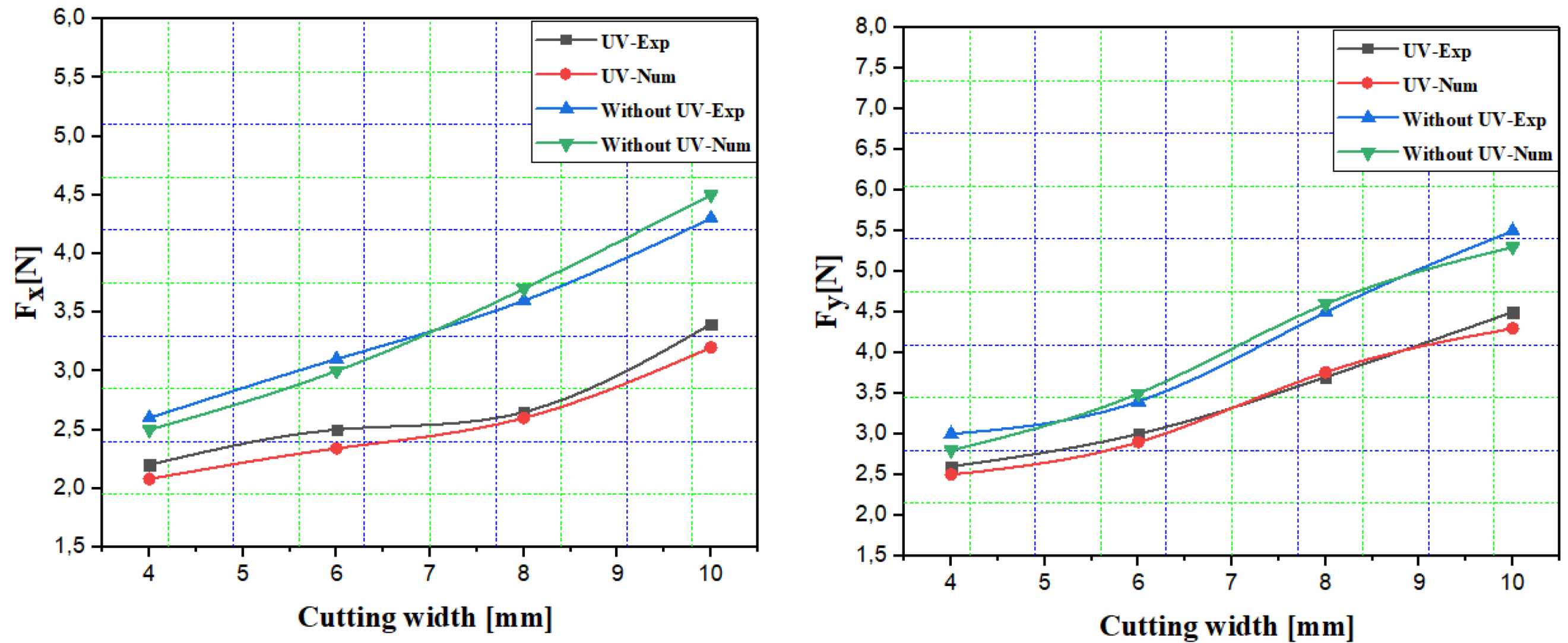
  • Cutting width effect: By widening the cutting width, the contact surface between the cutting tool and the workpiece becomes larger, which increases the frictional resistance during the cutting process. This leads to an increase in the force required for cutting.
  • Impact of feed rate: The cutting force increases with increasing feed rate, due to the increase in the volume of material removed per unit time. If the vibration amplitude remains constant, the propagation of cracks under the unit surface slows down, resulting in an increase in the required cutting force.
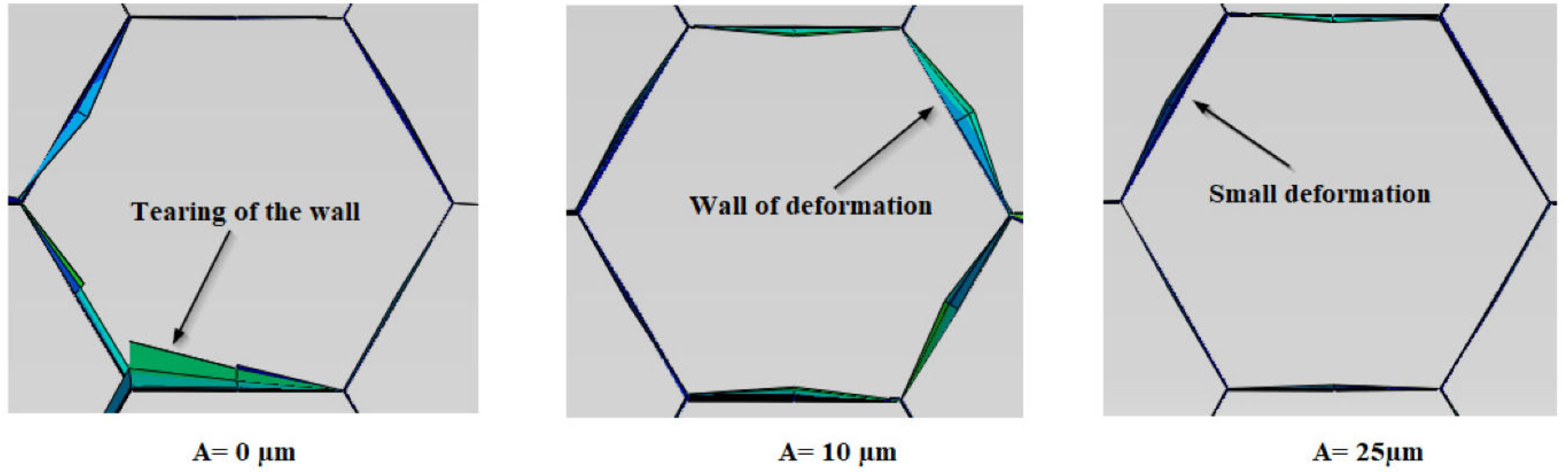
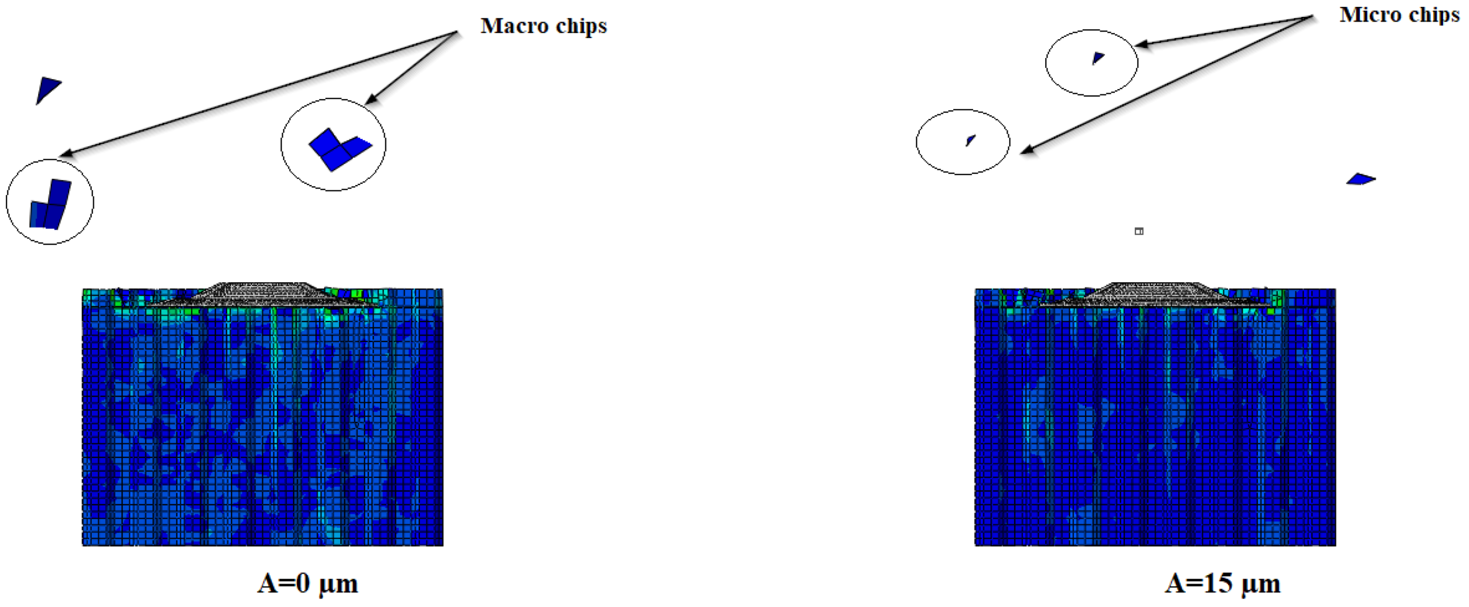
  • Effect of vibration amplitude: At a higher vibration amplitude, the crack propagation length under the intermittent impact of the cutting tool will be longer, leading to a decrease in cutting force. Therefore, an increase in vibration amplitude results in a reduction in cutting force.
Figure 26. Evolutions of the cutting force components (Fx, Fy): (a) feed rate; (b) spindle speed; (c) amplitude; (d) cutting width [189].
Machines 12 00561 g026
The vibration mode plays a crucial role in the cutting process. Compared with longitudinal–torsional ultrasonic vibration, longitudinal ultrasonic vibration generates a higher cutting force. Longitudinal–torsional vibrations, by simulating the action of a saw, facilitate the propagation of cracks under the cutting tool. This combination allows for more efficient cutting with reduced cutting force, resulting in better surface quality (Figure 27).
To better understand RUM-assisted machining with the UCSB cutting tool, Zarrouk et al. developed a three-dimensional numerical model based on the finite element method using the commercial software ABAQUS/Explicit in its version 6.17 [195,196,197]. Their model was able to accurately predict the influence of vibration amplitude on the cutting force components Fx and Fy, machined surface quality and chip size. These predictions are essential for optimizing the efficiency and accuracy of machining operations, as illustrated in Figure 28, Figure 29 and Figure 30.
The results presented by Zarrouk et al. highlight the significant impact of vibration amplitude on the machining process. Indeed, an appropriate vibration amplitude was identified as effectively reducing the cutting force components, resulting in a decrease in the force applied during cutting. In addition, this controlled vibration has helped to improve the quality of the machined surface by reducing defects and increasing the uniformity of its texture. At the same time, the use of this vibration amplitude has also been associated with the production of reduced-size chips, facilitating their management and reducing the risk of damage or disruption to the machining process. These findings highlight the importance of vibration amplitude in optimizing the machining performance of Nomex honeycomb composite structures and pave the way for significant improvements in this area.
Cutting tool wear during the machining of Nomex honeycomb structures is extensively covered in the literature. In this context, Zha et al. [198] analyzed how this wear can compromise processing accuracy. Their study proposes a radial difference calculation (RDC) method to evaluate tool wear and reveals that ultrasonic vibrations can reduce wear by up to 36%. Furthermore, it shows that heat treatments, particularly vacuum quenching, improve tool performance, with wear reductions of up to 64%. Xiang [66] focused on the kinematic aspects and processing mechanisms and developed cutting force models. He also compared the surface quality obtained with circular knife cutting tools and processing methods using ultrasonic longitudinal vibrations, with ultrasonic longitudinal–torsional vibrations applied to the Nomex honeycomb composite structure.
Based on the previous data, we observed that when milling the Nomex honeycomb structure assisted by ultrasonic vibrations, the differences between using a straight blade and a circular blade are significantly manifested in terms of performance, cutting quality and application. The straight blade, used mainly for straight line milling operations, has certain advantages in milling Nomex honeycomb structures with assistance from ultrasonic vibrations. Ultrasonic vibrations applied to a straight blade improve the cut quality by reducing the cutting forces required and decreasing tool wear. This technique allows for more precise cutting and a smoother surface finish, especially for flat sections and straight contours. However, the straight blade may be less suitable for complex or curved cuts, as it is optimized for linear movements. Ultrasonic vibrations help to reduce material build-up issues and burrs on the cut surface, but performance may be limited for more elaborate geometries. Additionally, the complexity of installing and maintaining ultrasonic systems can increase operational costs and setup times. In contrast, the circular blade, when used for ultrasonic vibration-assisted milling, offers distinct advantages for processing Nomex honeycomb structures. The circular blade is particularly effective for circular cutting or sawing operations, where it can make clean and uniform cuts on wider and thicker sections of material. The ultrasonic vibrations applied to the circular blade help reduce heat generation, which is crucial to avoid the warping of heat-sensitive material, such as Nomex. The circular blade also helps to maintain uniform cutting quality around the entire circumference of the tool, reducing cutting defects and improving surface finish. However, as with the straight blade, the integration of ultrasonic technology can add complexity to the system and incur additional costs for installation and maintenance. Additionally, vibrations can cause accelerated wear of the circular blade, especially if the system is not properly adjusted. In summary, the straight blade is ideal for linear milling operations and straight cuts, while the circular blade excels in circular cuts and sawing operations on larger sections. The use of ultrasonic vibration improves performance in both cases, but each blade type has specific advantages and disadvantages that must be considered based on application requirements and desired cutting geometries.

4. Conclusions

This study systematically analyzes the properties of Nomex honeycomb composite materials, the design parameters of processing systems, and the machining mechanisms. It explores the influence of geometric parameters of cutting tools on machining performance and examines the impact of processing parameters on cutting force and surface quality. In addition, it presents and evaluates theoretical models of the machining mechanisms, thus providing an in-depth and integrated understanding of the determining factors for optimizing the machining processes of Nomex honeycomb structures.
  • Conventional processing technologies dominate the large-scale production of Nomex honeycomb structures in the aerospace, defense and automotive industries due to their simplicity. However, they are subject to tool wear, dust pollution, surface damage and machining defects. Thus, to improve the accuracy and quality of Nomex honeycomb composite structure treatments, research is turning towards the development of ultrasound treatment technologies.
  • Ultrasonic machining is preferred for processing Nomex honeycomb composite structures due to the periodic contact between the cutting tool and the workpiece. The ultrasonic vibrations generated during contact reduce the cutting force, limit tool wear, minimize surface defects and ensure high surface quality. It is imperative to conduct in-depth research on the design parameters and the design of ultrasonic cutting tools, as well as ultrasonic cutting mechanisms, in order to effectively adapt them to the large-scale machining of Nomex honeycomb composite structures.
  • Cutting conditions significantly impact the cutting force and surface quality of Nomex honeycomb composites. Increasing the feed rate, cutting width, and depth increases cutting force and decreases surface quality. Higher spindle speeds and vibration amplitudes improve surface quality and reduce cutting force. Straight knives are used for roughing, while circular knives are preferred for finishing, routing, flat surfacing and profiling, taking advantage of the superior benefits of ultrasonic longitudinal–torsional vibration in terms of surface quality and reduced cutting forces compared to ultrasonic longitudinal vibration.
  • Machining defects and the surface quality of Nomex honeycomb structures vary between conventional machining and ultrasonic vibration-assisted machining, with the latter generally providing a better finish and fewer imperfections.
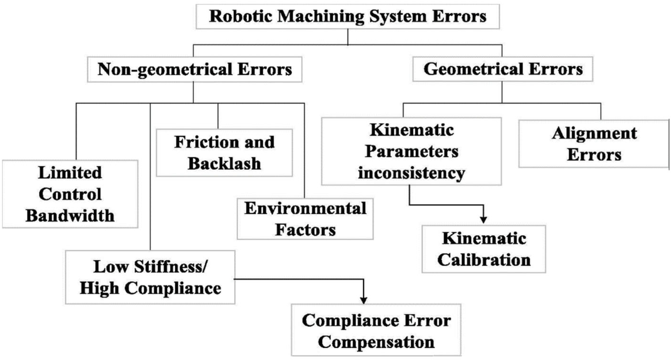
  • The merging of ultrasonic processing systems with robotic arms signifies an advancing technology, yet its application in robotic machining is hampered by several errors. Geometric errors stem from the misalignment of robot workstations and disparities between nominal and actual kinematic parameter values. Non-geometric errors arise from environmental factors like temperature, humidity and dust, alongside issues like friction, limited controller bandwidth and insufficient manipulator robot rigidity.

Author Contributions

Analysis, manuscript writing, investigation: T.Z.; supervision, methodology, investigation, analysis, M.N.; manuscript writing: J.-E.S.; analysis, manuscript writing: H.E. manuscript writing: M.A. manuscript writing: A.A. manuscript writing: M.L.L. All authors have read and agreed to the published version of the manuscript.

Funding

This research received no external funding.

Data Availability Statement

Data are contained within the article.

Conflicts of Interest

The authors declare no conflicts of interest.

Nomenclature

NHCNomex Honeycomb Composite Structure
UVAUltrasonic Vibration-Assisted Machining
CNCComputer Numerical Control

References

  1. Bitzer, T. Honeycomb core. In Honeycomb Technology: Materials, Design, Manufacturing, Applications and Testing; Springer: Dordrecht, The Netherlands, 1997; pp. 10–42. [Google Scholar]
  2. Wang, Z. Recent advances in novel metallic honeycomb structure. Compos. Part B Eng. 2019, 166, 731–741. [Google Scholar] [CrossRef]
  3. Hexcel Corporation. HexWebTM Honeycomb Attributes and Properties; Hexcel Corporation: Stamford, CT, USA, 1999. [Google Scholar]
  4. Keshavanarayana, S.R.; Shahverdi, H.; Kothare, A.; Yang, C.; Bingenheimer, J. The effect of node bond adhesive fillet on uniaxial in-plane responses of hexagonal honeycomb core. Compos. Struct. 2017, 175, 111–122. [Google Scholar] [CrossRef]
  5. Jansons, J.; Kulakov, V.; Aniskevich, A.; Lagzdiņš, A. Structural composites—From aerospace to civil engineering applications. Innov. Technol. News 2012, 4, 3–12. [Google Scholar]
  6. Hayes, B.S.; Gammon, L.M. Optical Microscopy of Fiber-Reinforced Composites; ASM International: Almere, The Netherlands, 2010. [Google Scholar]
  7. Musselman, M. Automotive Composites: A Design and Manufacturing Guide, 2nd ed.; Ray Publishing: Wheat Ridge, CO, USA, 2006. [Google Scholar]
  8. Ratcliffe, J.G.; Czabaj, M.W.; Jackson, W.C. A model for simulating the response of aluminum honeycomb structure to transverse loading. In Proceedings of the 15th US-Japan Conference on Composite Materials Meeting, Arlington, TX, USA, 1–3 October 2012. [Google Scholar]
  9. Heimbs, S. Virtual testing of sandwich core structures using dynamic finite element simulations. Comput. Mater. Sci. 2009, 45, 205–216. [Google Scholar] [CrossRef]
  10. Giglio, M.; Manes, A.; Gilioli, A. Investigations on sandwich core properties through an experimental–numerical approach. Compos. Part B Eng. 2012, 43, 361–374. [Google Scholar] [CrossRef]
  11. Price, T.L.; Dalley, G.; McCullough, P.C.; Choquette, L. Handbook: Manufacturing Advanced Composite Components for Airframes; Federal Aviation Administration Washington DC Office of Aviation Research: Washington, DC, USA, 1997. [Google Scholar]
  12. Yang, X.; Sun, Y.; Yang, J.; Pan, Q. Out-of-plane crashworthiness analysis of bio-inspired aluminum honeycomb patterned with horseshoe mesostructure. Thin Walled Struct. 2018, 125, 1–11. [Google Scholar] [CrossRef]
  13. Liu, S.; Zhang, Y.; Liu, P. New analytical model for heat transfer efficiency of metallic honeycomb structures. Int. J. Heat Mass Transf. 2008, 51, 6254–6258. [Google Scholar] [CrossRef]
  14. Hong, S.T.; Pan, J.; Tyan, T.; Prasad, P. Quasi-static crush behavior of aluminum honeycomb specimens under non-proportional compression-dominant combined loads. Int. J. Plast. 2006, 22, 1062–1088. [Google Scholar] [CrossRef]
  15. Dharmasena, K.P.; Wadley, H.N.; Xue, Z.; Hutchinson, J.W. Mechanical response of metallic honeycomb sandwich panel structures to high-intensity dynamic loading. Int. J. Impact Eng. 2008, 35, 1063–1074. [Google Scholar] [CrossRef]
  16. Cote, F.; Deshpande, V.S.; Fleck, N.A.; Evans, A.G. The out-of-plane compressive behavior of metallic honeycombs. Mater. Sci. Eng. A 2004, 380, 272–280. [Google Scholar] [CrossRef]
  17. de Dios Rodriguez-Ramirez, J.; Castanie, B.; Bouvet, C. Experimental and numerical analysis of the shear nonlinear behaviour of Nomex honeycomb core: Application to insert sizing. Compos. Struct. 2018, 193, 121–139. [Google Scholar] [CrossRef]
  18. Kim, G.; Sterkenburg, R.; Tsutsui, W. Investigating the effects of fluid intrusion on Nomex honeycomb sandwich structures with carbon fiber facesheets. Compos. Struct. 2018, 206, 535–549. [Google Scholar] [CrossRef]
  19. Abd Kadir, N.; Aminanda, Y.; Ibrahim, M.S.; Mokhtar, H. Experimental study of low-velocity impact on foam-filled Kraft paper honeycomb structure. In IOP Conference Series: Materials Science and Engineering; IOP Publishing: Bristol, UK, 2018; Volume 290, p. 012082. [Google Scholar]
  20. Chen, Z.; Yan, N. Investigation of elastic moduli of Kraft paper honeycomb core sandwich panels. Compos. Part B Eng. 2012, 43, 2107–2114. [Google Scholar] [CrossRef]
  21. Toribio, M.G.; Spearing, S.M. Compressive response of notched glass-fiber epoxy/honeycomb sandwich panels. Compos. Part A Appl. Sci. Manuf. 2001, 32, 859–870. [Google Scholar] [CrossRef]
  22. Shahdin, A.; Mezeix, L.; Bouvet, C.; Morlier, J.; Gourinat, Y. Fabrication and mechanical testing of glass fiber entangled sandwich beams: A comparison with honeycomb and foam sandwich beams. Compos. Struct. 2009, 90, 404–412. [Google Scholar] [CrossRef]
  23. Liu, L.; Meng, P.; Wang, H.; Guan, Z. The flatwise compressive properties of Nomex honeycomb core with debonding imperfections in the double cell wall. Compos. Part B Eng. 2015, 76, 122–132. [Google Scholar] [CrossRef]
  24. Karakoç, A.; Santaoja, K.; Freund, J. Simulation experiments on the effective in-plane compliance of the honeycomb materials. Compos. Struct. 2013, 96, 312–320. [Google Scholar] [CrossRef]
  25. Roy, R.; Park, S.J.; Kweon, J.H.; Choi, J.H. Characterization of Nomex honeycomb core constituent material mechanical properties. Compos. Struct. 2014, 117, 255–266. [Google Scholar] [CrossRef]
  26. Kim, D.S.; Lee, J.R. Compressive mechanical properties of the Nomex/thermoset honeycomb cores. Polym. Adv. Technol. 1997, 8, 1–7. [Google Scholar] [CrossRef]
  27. Luo, Y.Q.; Hao, W. Study on properties of T722 Nomex honeycomb. Hi-Tech. Fiber Appl. 2009, 34, 34–37. [Google Scholar]
  28. Ke, M.; Jianfu, Z.; Pingfa, F.; Zhijun, W.; Dingwen, Y.; Ahmad, S. Design and implementation of a mini ultrasonic cutting system for Nomex honeycomb composites. In Proceedings of the 2019 16th International Bhurban Conference on Applied Sciences and Technology (IBCAST), Islamabad, Pakistan, 8–12 January 2019; pp. 148–152. [Google Scholar]
  29. Wenli, C.; Chao, Y.; Qiyan, Q. Honeycomb sandwich structure and manufacturing process in aviation industry. Aeronaut. Manuf. Technol. 2015, 7, 94–98. [Google Scholar]
  30. Asprone, D.; Auricchio, F.; Menna, C.; Morganti, S.; Prota, A.; Reali, A. Statistical finite element analysis of the buckling behavior of honeycomb structures. Compos. Struct. 2013, 105, 240–255. [Google Scholar] [CrossRef]
  31. Zhou, H.; Xu, P.; Xie, S.; Feng, Z.; Wang, D. Mechanical performance and energy absorption properties of structures combining two Nomex honeycombs. Compos. Struct. 2018, 185, 524–536. [Google Scholar] [CrossRef]
  32. Roy, R.; Nguyen, K.H.; Park, Y.B.; Kweon, J.H.; Choi, J.H. Testing and modeling of Nomex honeycomb sandwich Panels with bolt insert. Compos. Part B Eng. 2014, 56, 762–769. [Google Scholar] [CrossRef]
  33. Ahmad, S.; Zhang, J.; Feng, P.; Yu, D.; Wu, Z.; Ke, M. Research on design and FE simulations of novel ultrasonic circular saw blade (UCSB) cutting tools for rotary ultrasonic machining of Nomex honeycomb composites. In Proceedings of the 2019 16th International Bhurban Conference on Applied Sciences and Technology, Islamabad, Pakistan, 8–12 January 2019; pp. 113–119. [Google Scholar]
  34. Heimbs, S.; Middendorf, P.; Hampf, C.; Hähnel, F.; Wolf, K. Aircraft sandwich structures with folded core under impact load. In Proceedings of the 8th International Conference on Sandwich Structures, ICSS8, Porto, Portugal, 6–8 May 2008; pp. 369–380. [Google Scholar]
  35. Kim, K.S.; Chin, I.J.; Sung, I.K.; Min, K.S. Curing of Nomex/phenolic and kraft/phenolic honeycombs. Korea Polym. J. 1995, 3, 35–40. [Google Scholar]
  36. Feng, H.; Liu, L.; Zhao, Q. Experimental and numerical investigation of the effect of entrapped air on the mechanical response of Nomex honeycomb under flatwise compression. Compos. Struct. 2017, 182, 617–627. [Google Scholar] [CrossRef]
  37. Zhou, Z.; Wang, Z.; Zhao, L.; Shu, X. Experimental investigation on the yield behavior of Nomex honeycombs under combined shear-compression. Lat. Am. J. Solids Struct. 2012, 9, 515–530. [Google Scholar] [CrossRef]
  38. Gilioli, A.; Sbarufatti, C.; Manes, A.; Giglio, M. Compression after impact test (CAI) on Nomex honeycomb sandwich panels with thin aluminum skins. Compos. Part B Eng. 2014, 67, 313–325. [Google Scholar] [CrossRef]
  39. Foo, C.C.; Chai, G.B.; Seah, L.K. Mechanical properties of Nomex material and Nomex honeycomb structure. Compos. Struct. 2017, 80, 588–594. [Google Scholar] [CrossRef]
  40. Karakoç, A.; Freund, J. Experimental studies on mechanical properties of cellular structures using Nomex honeycomb cores. Compos. Struct. 2012, 94, 2017–2024. [Google Scholar] [CrossRef]
  41. Liu, Y.; Liu, W.; Gao, W.; Zhang, L.; Zhang, E. Mechanical responses of a composite sandwich structure with Nomex honeycomb core. J. Reinf. Plast. Compos. 2019, 38, 601–615. [Google Scholar] [CrossRef]
  42. Seemann, R.; Krause, D. Numerical modelling of Nomex honeycomb sandwich cores at meso-scale level. Compos. Struct. 2017, 159, 702–718. [Google Scholar] [CrossRef]
  43. Gornet, L.; Marguet, S.; Marckmann, G. Modeling of Nomex honeycomb cores, linear and nonlinear behaviors. Mech. Adv. Mater. Struct. 2007, 14, 589–601. [Google Scholar] [CrossRef]
  44. Roy, R.; Kweon, J.H.; Choi, J.H. Meso-scale finite element modeling of Nomex honeycomb cores. Adv. Compos. Mater. 2014, 23, 17–29. [Google Scholar] [CrossRef]
  45. Rodríguez-Ramírez, J.D.D.; Castanié, B.; Bouvet, C. Damage Mechanics Modelling of the shear nonlinear behavior of Nomex honeycomb core. Application to sandwich beams. Mech. Adv. Mater. Struct. 2020, 27, 80–89. [Google Scholar] [CrossRef]
  46. Castanié, B.; Bouvet, C.; Aminanda, Y.; Barrau, J.J.; Thévenet, P. Modelling of low-energy/low-velocity impact on Nomex honeycomb sandwich structures with metallic skins. Int. J. Impact Eng. 2008, 35, 620–634. [Google Scholar] [CrossRef]
  47. Herup, E.J.; Palazotto, A.N. Low-velocity impact damage initiation in graphite/epoxy/Nomex honeycomb-sandwich plates. Compos. Sci. Technol. 1998, 57, 1581–1598. [Google Scholar] [CrossRef]
  48. Gibson, L.J. Cellular solids. MRS Bull. 2003, 28, 270–274. [Google Scholar] [CrossRef]
  49. Gornet, L.; Marguet, S.; Marckmann, G. Finite Element modeling of Nomex honeycomb cores: Failure and effective elastic properties. Int. J. Comput. Mater. Contin. Technol. Sci. 2006, 4, 11–22. [Google Scholar]
  50. Qiu, K.; Wang, Z.; Zhang, W. The effective elastic properties of flexible hexagonal honeycomb cores with consideration for geometric nonlinearity. Aerosp. Sci. Technol. 2016, 58, 258–266. [Google Scholar] [CrossRef]
  51. Rion, J.; Leterrier, Y.; Månson, J.A.E. Prediction of the adhesive fillet size for skin to honeycomb core bonding in ultra-light sandwich structures. Compos. Part A Appl. Sci. Manuf. 2008, 39, 1547–1555. [Google Scholar] [CrossRef]
  52. Chen, D.H. Bending deformation of honeycomb consisting of regular hexagonal cells. Compos. Struct. 2011, 93, 736–746. [Google Scholar] [CrossRef]
  53. Aktay, L.; Johnson, A.F.; Kröplin, B.H. Numerical modelling of honeycomb core crush behaviour. Eng. Fract. Mech. 2008, 75, 2616–2630. [Google Scholar] [CrossRef]
  54. Chawla, A.; Mukherjee, S.; Kumar, D.; Nakatani, T.; Ueno, M. Prediction of crushing behaviour of honeycomb structures. Int. J. Crashworthiness 2003, 8, 229–235. [Google Scholar] [CrossRef]
  55. Li, K.; Gao, X.L.; Wang, J. Dynamic crushing behavior of honeycomb structures with irregular cell shapes and non-uniform cell wall thickness. Int. J. Solids Struct. 2007, 44, 5003–5026. [Google Scholar] [CrossRef]
  56. Yang, M.Y.; Huang, J.S.; Sam, C.P. In-plane elastic moduli and plastic collapse strength of regular hexagonal honeycombs with dual imperfections. Int. J. Mech. Sci. 2008, 50, 43–54. [Google Scholar] [CrossRef]
  57. Wilbert, A.; Jang, W.Y.; Kyriakides, S.; Floccari, J.F. Buckling and progressive crushing of laterally loaded honeycomb. Int. J. Solids Struct. 2011, 48, 803–816. [Google Scholar] [CrossRef]
  58. Hill, R. A theory of the yielding and plastic flow of anisotropic metals. Proc. R. Soc. London. Ser. A Math. Phys. Sci. 1948, 193, 281–297. [Google Scholar]
  59. Yaozhi, X. Study on Cutting Tool Design and Processing Technology of Ultrasonic-Assisted Cutting of Honeycomb Composites. Master’s Thesis, Tsinghua University, Beijing, China, 2019. [Google Scholar]
  60. Norvilie, H.S.; Tibor, E. Process for Machining Expanded Honeycomb. U.S. Patent 3,413,708, 1968. [Google Scholar]
  61. Nilsen, J.S.; Wadsworth, O. Method and Apparatus for Machining and for Holding during Machining Honeycomb Material. U.S. Patent 2,905,064, 1959. [Google Scholar]
  62. Wang, F.; Wang, Y. Investigate on milling force of cryogenic cooling processing aluminum honeycomb treated by ice fixation. Int. J. Adv. Manuf. Technol. 2018, 98, 1253–1265. [Google Scholar] [CrossRef]
  63. Jaafar, M.; Atlati, S.; Makich, H.; Nouari, M.; Moufki, A.; Julliere, B. A 3D FE modeling of machining process of Nomex honeycomb core: Influence of the cell structure behaviour and specific tool geometry. Procedia CIRP 2017, 58, 505–510. [Google Scholar] [CrossRef]
  64. An, Q.; Dang, J.; Ming, W.; Qiu, K.; Chen, M. Experimental and numerical studies on defect characteristics during milling of aluminum honeycomb core. J. Manuf. Sci. Eng. 2019, 141, 031006. [Google Scholar] [CrossRef]
  65. Griffith, C.G.; Herbert, J.T.A. Method of Machining Honeycomb Core. U.S. Patent 2,855,664, 1958. [Google Scholar]
  66. Carl, R. Three-Dimensional Honeycomb Core Machining Apparatus and Method. U.S. Patent 13/707,670, 2012. [Google Scholar]
  67. Hirayama, A. Method for Cutting Honeycomb Core. U.S. Patent 6740268 B2, 1991. [Google Scholar]
  68. RThiagaraj, R.M.; Chris, J.R.; McCullough, S. Mishra, Method of Repairing, Splicing, Joining, Machining, and Stabilizing Honeycomb Core Using Pourable Structural Foam and a Structure Incorporating the Same. U.S. Patent 20140120305 A1, 2014. [Google Scholar]
  69. Bridge Type Gantry Machine Tool, C.R Onsurd. 2019. Available online: https://www.cronsrud.com/honeycomb_cell.html (accessed on 12 November 2019).
  70. High-Precision, 5-Axes Control Vertical Machining Center, DMG MORI. 2019. Available online: https://en.dmgmori.com/products/machines/milling/5-axis-milling/nmv/nmv-5000-dcg (accessed on 12 November 2019).
  71. Jin, C.Z. Study on reliability of new fixture method for Nomex honeycomb. Adv. Mater. Res. 2012, 415, 3–13. [Google Scholar] [CrossRef]
  72. NEXAM. Cutting Tools for Aircraft Manufacturers and MRO Companies, Cathalogue; NEXAM: Lomma, Sweden, 2012. [Google Scholar]
  73. LMT.ONSRUD. Milling and Drilling Tools for Composite and Honeycomb Materials; LMT.ONSRUD: Waukegan, IL, USA, 2010. [Google Scholar]
  74. Poutord, A. Étude du Perçage à Sec de L‘empilage Ti6Al4V/Composite Fibre de Carbone. Ph.D. Thesis, Ecole Nationale Supérieure d‘arts et Métiers-ENSAM, Paris, France, 2014. [Google Scholar]
  75. Mendoza, M.M.; Eman, K.F.; Wu, S.M. Development of a new milling cutter for aluminium honeycomb. Int. J. Mach. Tool Des. Res. 1983, 23, 81–91. [Google Scholar] [CrossRef]
  76. Seco. Fraises Carbure Monoblocs Hautes Performances Pour Matériaux Composites; Seco Tools: Troy, MI, USA, 2010. [Google Scholar]
  77. Lund, W.C.; Pedersen, D.E. Milling Cutter for Honeycomb Core Material. U.S. Patent 4,907,920, 1990. [Google Scholar]
  78. Jaafar, M. Étude Expérimentale et Simulation Numérique de L’usinage des Matériaux en nids D’abeilles: Application au Fraisage des Structures Nomex et Aluminium. Ph.D. Dissertation, Université de Lorraine, Nancy, France, 2018. [Google Scholar]
  79. Nasedkin, Y.V.; Tsarev, V.F.; Zelenina, I.V. Cutting of aramide fiber-reinforced plastics by Co2 laser. Mech. Compos. Mater. 1999, 35, 259–264. [Google Scholar] [CrossRef]
  80. Geng, D.; Zhang, D.; Xu, Y.; He, F.; Liu, D.; Duan, Z. Rotary ultrasonic elliptical machining for side milling of CFRP: Tool performance and surface integrity. Ultrasonics 2015, 59, 128–137. [Google Scholar] [CrossRef]
  81. Khairusshima, M.N.; Hassan, C.C.; Jaharah, A.G.; Amin, A.K.M.; Idriss, A.M. Effect of chilled air on tool wear and workpiece quality during milling of carbon fibre-reinforced plastic. Wear 2013, 302, 1113–1123. [Google Scholar] [CrossRef]
  82. Zitoune, R.; El Mansori, M.; Krishnaraj, V. Tribo-functional design of double cone drill implications in tool wear during drilling of copper mesh/CFRP/woven ply. Wear 2013, 302, 1560–1567. [Google Scholar] [CrossRef]
  83. Haddad, M.; Zitoune, R.; Bougherara, H.; Eyma, F.; Castanié, B. Study of trimming damages of CFRP structures in function of the machining processes and their impact on the mechanical behavior. Compos. Part B Eng. 2014, 57, 136–143. [Google Scholar] [CrossRef]
  84. Saleem, M.; Toubal, L.; Zitoune, R.; Bougherara, H. Investigating the effect of machining processes on the mechanical behavior of composite plates with circular holes. Compos. Part A Appl. Sci. Manuf. 2013, 55, 169–177. [Google Scholar] [CrossRef]
  85. Teti, R. Machining of composite materials. CIRP Ann. 2002, 51, 611–634. [Google Scholar] [CrossRef]
  86. Karpat, Y.; Bahtiyar, O.; Değer, B. Mechanistic force modeling for milling of unidirectional carbon fiber reinforced polymer laminates. Int. J. Mach. Tools Manuf. 2012, 56, 79–93. [Google Scholar] [CrossRef]
  87. Haddad, M.; Zitoune, R.; Eyma, F.; Castanie, B. Study of the surface defects and dust generated during trimming of CFRP: Influence of tool geometry, machining parameters and cutting speed range. Compos. Part A Appl. Sci. Manuf. 2014, 66, 142–154. [Google Scholar] [CrossRef]
  88. Khan, S.; Loken, H.Y. Bonding of sandwich structures—The facesheet/honeycomb interface—A phenomenological study. Proc. SAMPE 2007, 1–9. [Google Scholar]
  89. Mughal, K.H.; Qureshi, M.A.M.; Jamil, M.F.; Ahmad, S.; Khalid, F.A.; Qaiser, A.A.; Maqbool, A.; Raza, S.F.; Zhang, J. Investigation of hybrid ultrasonic machining process of Nomex honeycomb composite using a toothed disc cutter. Ultrasonics 2024, 141, 107343. [Google Scholar] [CrossRef]
  90. Yuan, X.; Fan, C.; Xu, J.; Cao, W.; Zhou, W.; Jiang, E.; Ma, W.; Xu, C.; Feng, P.; Feng, F. Dominating influence of cutting-edge lead angles on arc-trajectory machining of Nomex honeycomb composites by using a straight blade cutter. Eng. Sci. Technol. Int. J. 2024, 49, 101601. [Google Scholar] [CrossRef]
  91. Jiang, E.; Yue, Q.; Xu, J.; Fan, C.; Song, G.; Yuan, X.; Ma, Y.; Yu, X.; Yang, P.; Feng, P.; et al. A wear testing method of straight blade tools for Nomex honeycomb composites machining. Wear 2024, 546, 205325. [Google Scholar] [CrossRef]
  92. Jaafar, M.; Nouari, M.; Makich, H.; Moufki, A. 3D numerical modeling and experimental validation of machining Nomex honeycomb materials. Int. J. Adv. Manuf. Technol. 2021, 115, 2853–2872. [Google Scholar] [CrossRef]
  93. Jaafar, M.; Makich, H.; Nouari, M. A new criterion to evaluate the machined surface quality of the Nomex honeycomb materials. J. Manuf. Process. 2021, 69, 567–582. [Google Scholar] [CrossRef]
  94. Zarrouk, T.; Nouari, M.; Makich, H. Simulated study of the machinability of the Nomex honeycomb structure. J. Manuf. Mater. Process. 2023, 7, 28. [Google Scholar] [CrossRef]
  95. Zarrouk, T.; Salhi, J.E.; Nouari, M.; Salhi, M.; Kodad, J. Influence of the cutting tool geometry on milling aluminum honeycomb structures. Int. J. Adv. Manuf. Technol. 2023, 126, 313–324. [Google Scholar] [CrossRef]
  96. Zarrouk, T.; Salhi, J.E.; Nouari, M.; Salhi, M.; Chaabelasri, E.; Makich, H.; Salhi, N. Modeling machining of aluminum honeycomb structure. Int. J. Adv. Manuf. Technol. 2022, 123, 2481–2500. [Google Scholar] [CrossRef]
  97. Singh, R.P.; Singhal, S. Rotary ultrasonic machining: A review. Mater. Manuf. Process. 2016, 31, 1795–1824. [Google Scholar] [CrossRef]
  98. Rao, R.V.; Pawar, P.J.; Davim, J.P. Parameter optimization of ultrasonic machining process using nontraditional optimization algorithms. Mater. Manuf. Process. 2010, 25, 1120–1130. [Google Scholar] [CrossRef]
  99. Kang, B.; Kim, G.W.; Yang, M.; Cho, S.H.; Park, J.K. A study on the effect of ultrasonic vibration in nanosecond laser machining. Opt. Lasers Eng. 2012, 50, 1817–1822. [Google Scholar] [CrossRef]
  100. Xu, W.X.; Zhang, L.C. Ultrasonic vibration-assisted machining: Principle, design and application. Adv. Manuf. 2015, 3, 173–192. [Google Scholar] [CrossRef]
  101. Xu, W.; Zhang, L.C.; Wu, Y. Elliptic vibration-assisted cutting of fibre-reinforced polymer composites: Understanding the material removal mechanisms. Compos. Sci. Technol. 2014, 92, 103–111. [Google Scholar] [CrossRef]
  102. Thoe, T.B.; Aspinwall, D.K.; Wise, M.L.H. Review on ultrasonic machining. Int. J. Mach. Tools Manuf. 1998, 38, 239–255. [Google Scholar] [CrossRef]
  103. Koval’chenko, M.S.; Paustovskii, A.V.; Perevyazko, V.A. Influence of properties of abrasive materials on the effectiveness of ultrasonic machining of ceramics. Sov. Powder Metall. Met. Ceram. (Engl. Transl.) 1986, 25, 560–562. [Google Scholar] [CrossRef]
  104. Singh, R.; Khamba, J.S. Ultrasonic machining of titanium and its alloys: A review. J. Mater. Process. Technol. 2006, 173, 125–135. [Google Scholar] [CrossRef]
  105. Kuo, K.L. Experimental investigation of brittle material milling using rotary ultrasonic machining. In Proceedings of the 35th International MATADOR Conference: Formerly the International Machine Tool Design and Research Conference, Taipei, Taiwan, 27 July 2007; pp. 195–198. [Google Scholar]
  106. Kuo, K.L.; Tsao, C.C. Rotary ultrasonic-assisted milling of brittle materials. Trans. Nonferrous Met. Soc. China 2012, 22, s793–s800. [Google Scholar] [CrossRef]
  107. Kumar, J.; Khamba, J.S.; Mohapatra, S.K. An investigation into the machining characteristics of titanium using ultrasonic machining. Int. J. Mach. Mach. Mater. 2008, 3, 143–161. [Google Scholar] [CrossRef]
  108. Churi, N. Rotary Ultrasonic Machining of Hard-to-Machine Materials. Doctoral Dissertation, Kansas State University, Manhattan, KS, USA, 2010. [Google Scholar]
  109. Pei, Z.J.; Ferreira, P.M.; Kapoor, S.G.; Haselkorn, M.B.A.C. Rotary ultrasonic machining for face milling of ceramics. Int. J. Mach. Tools Manuf. 1995, 35, 1033–1046. [Google Scholar] [CrossRef]
  110. DMG MORI USA. Ultrasonic Machine Tools. 2019. Available online: https://us.dmgmori.com/products (accessed on 12 November 2019).
  111. American GFM USA. Ultrasonic Machine Tools. 2019. Available online: http://www.agfm.com/new/Cutting/Intro.html (accessed on 12 November 2019).
  112. Tongtai Machine & Tool Co., Ltd. China. Ultrasonic Assisted Machine Tools Manufacturer. 2019. Available online: http://www.tongtai.com.tw/en/techpage.php?id=1 (accessed on 12 November 2019).
  113. MS Ultrasonic Technology Group Germany. Ultrasonic Machine Tools Manufacturer. 2019. Available online: https://www.msultrasonic.com/cms/en/ultrasonic_technology/ (accessed on 12 November 2019).
  114. OPTIPRO USA. Ultrasonic Machining Centers. 2019. Available online: https://www.optipro.com/optical-manufacturing/ultrasonic-machining/ (accessed on 12 November 2019).
  115. CRENO USA. Ultrasonic Machine Tools and Robots. 2019. Available online: https://www.creno-industry.com/ultrasonic/ (accessed on 12 November 2019).
  116. COMI Group Italy. Ultrasonic Machine Tool. 2019. Available online: http://www.comispa.it/ (accessed on 12 November 2019).
  117. SONOTEC Japan. Ultrasonic Systems. Available online: https://www.sonotec.com/en/ (accessed on 12 November 2019).
  118. MAQ Sweden. Ultrasonic Machine Tools. 2019. Available online: https://www.maqab.com/index.php/product/technology/ (accessed on 12 November 2019).
  119. Skoczypiec, S. Research on ultrasonically assisted electrochemical machining process. Int. J. Adv. Manuf. Technol. 2011, 52, 565–574. [Google Scholar] [CrossRef]
  120. Perusich, S.A.; Alkire, R.C. Ultrasonically induced cavitation studies of electrochemical passivity and transport mechanisms: II. Experimental. J. Electrochem. Soc. 1991, 138, 708. [Google Scholar] [CrossRef]
  121. Ruszaj, A.; Zybura, M.; Żurek, R.; Skrabalak, G. Some aspects of the electrochemical machining process supported by electrode ultrasonic vibrations optimization. Proc. Inst. Mech. Eng. Part B J. Eng. Manuf. 2003, 217, 1365–1371. [Google Scholar] [CrossRef]
  122. Skoczypiec, S. Research on Ultrasonically Assisted Electrochemical Machining with Universal Electrode Tool. Ph.D. Thesis, Cracow University of Technology, Kraków, Poland, 2006. (In Polish). [Google Scholar]
  123. Skoczypiec, S.; Ruszaj, A. Application of ultrasonic vibration to improve technological factors in electrochemical machining of titanium alloys. In Proceedings of the International Symposium on Electrochemical Machining Technology INSECT, Cheminitz University of Technology, Chemnitz, Germany, 25–26 October 2007; pp. 143–148. [Google Scholar]
  124. Zhang, Q.H.; Zhang, J.H.; Deng, J.X.; Qin, Y.; Niu, Z.W. Ultrasonic vibration electrical discharge machining in gas. J. Mater. Process. Technol. 2002, 129, 135–138. [Google Scholar] [CrossRef]
  125. Kunieda, M.; Yoshida, M.; Taniguchi, N. Electrical discharge machining in gas. CIRP Ann. 1997, 46, 143–146. [Google Scholar] [CrossRef]
  126. Srivastava, V.; Pandey, P.M. Study of ultrasonic assisted cryogenically cooled EDM process using sintered (Cu–TiC) tooltip. J. Manuf. Process. 2013, 15, 158–166. [Google Scholar] [CrossRef]
  127. Kremer, D.; Lebrun, J.L.; Hosari, B.; Moisan, A. Effects of ultrasonic vibrations on the performances in EDM. CIRP Ann. 1989, 38, 199–202. [Google Scholar] [CrossRef]
  128. Kremer, D.; Lhiaubet, C.; Moisan, A. A study of the effect of synchronizing ultrasonic vibrations with pulses in EDM. CIRP Ann. 1991, 40, 211–214. [Google Scholar] [CrossRef]
  129. Khatri, B.C.; Rathod, P.; Valaki, J.B. Ultrasonic vibration–assisted electric discharge machining: A research review. Proc. Inst. Mech. Eng. Part B J. Eng. Manuf. 2016, 230, 319–330. [Google Scholar] [CrossRef]
  130. Zhixin, J.; Jianhua, Z.; Xing, A. Ultrasonic vibration pulse electro-discharge machining of holes in engineering ceramics. J. Mater. Process. Technol. 1995, 53, 811–816. [Google Scholar] [CrossRef]
  131. Murti, V.S.R.; Philip, P.K. A comparative analysis of machining characteristics in ultrasonic assisted EDM by the response surface methodology. Int. J. Prod. Res. 1987, 25, 259–272. [Google Scholar] [CrossRef]
  132. Gao, C.; Liu, Z. A study of ultrasonically aided micro-electrical-discharge machining by the application of workpiece vibration. J. Mater. Process. Technol. 2003, 139, 226–228. [Google Scholar] [CrossRef]
  133. Hoang, K.T.; Yang, S.H. A study on the effect of different vibration-assisted methods in micro-WEDM. J. Mater. Process. Technol. 2013, 213, 1616–1622. [Google Scholar] [CrossRef]
  134. Guo, Z.N.; Lee, T.C.; Yue, T.M.; Lau, W.S. A study of ultrasonic-aided wire electrical discharge machining. J. Mater. Process. Technol. 1997, 63, 823–828. [Google Scholar] [CrossRef]
  135. Lipchanskii, A.B. Experimental investigation of wire electrical discharge machining assisted with ultrasonic vibration. Sov. Surf. Eng. Appl. Electrochem. 1991, 1, 5. [Google Scholar]
  136. Yu, Z.Y.; Zhang, Y.; Li, J.; Luan, J.; Zhao, F.; Guo, D. High aspect ratio micro-hole drilling aided with ultrasonic vibration and planetary movement of electrode by micro-EDM. CIRP Ann. 2009, 58, 213–216. [Google Scholar] [CrossRef]
  137. Prihandana, G.S.; Mahardika, M.; Hamdi, M.; Wong, Y.S.; Mitsui, K. Effect of micro-powder suspension and ultrasonic vibration of dielectric fluid in micro-EDM processes—Taguchi approach. Int. J. Mach. Tools Manuf. 2009, 49, 1035–1041. [Google Scholar] [CrossRef]
  138. Ghiculescu, D.; Marinescu, N.; Nanu, S.; Ghiculescu, D. EQUIPMENT FOR ULTRASONIC AIDING OF WIRE ELECTRODIS-CHARGE MACHINING. Acad. J. Manuf. Eng. 2011, 9, 18. [Google Scholar]
  139. Ichikawa, T.; Natsu, W. Realization of micro-EDM under ultra-small discharge energy by applying ultrasonic vibration to machining fluid. Procedia CIRP 2013, 6, 326–331. [Google Scholar] [CrossRef]
  140. Ghoreishi, M.; Atkinson, J. A comparative experimental study of machining characteristics in vibratory, rotary and vibro-rotary electro-discharge machining. J. Mater. Process. Technol. 2002, 120, 374–384. [Google Scholar] [CrossRef]
  141. Shervani-Tabar, M.T.; Maghsoudi, K.; Shabgard, M.R. Effects of simultaneous ultrasonic vibration of the tool and the workpiece in ultrasonic assisted EDM. Int. J. Comput. Methods Eng. Sci. Mech. 2013, 14, 1–9. [Google Scholar] [CrossRef]
  142. Abdullah, A.; Shabgard, M.R. Effect of ultrasonic vibration of tool on electrical discharge machining of cemented tungsten carbide (WC-Co). Int. J. Adv. Manuf. Technol. 2008, 38, 1137–1147. [Google Scholar] [CrossRef]
  143. Marinescu, N.I.; Ghiculescu, D.; Jitianu, G. Solutions for technological performances increasing at ultrasonic aided electrodischarge machining. Int. J. Mater. Form. 2009, 2, 681–684. [Google Scholar] [CrossRef]
  144. Zhang, Q.H.; Zhang, J.H.; Ren, S.F.; Deng, J.X.; Ai, X. Study on technology of ultrasonic vibration aided electrical discharge machining in gas. J. Mater. Process. Technol. 2004, 149, 640–644. [Google Scholar] [CrossRef]
  145. Iwai, M.; Ninomiya, S.; Suzuki, K. Improvement of EDM properties of PCD with electrode vibrated by ultrasonic transducer. Procedia CIRP 2013, 6, 146–150. [Google Scholar] [CrossRef]
  146. Silberschmidt, V.V.; Mahdy, S.M.; Gouda, M.A.; Naseer, A.; Maurotto, A.; Roy, A. Surface-roughness improvement in ultrasonically assisted turning. Procedia CIRP 2014, 13, 49–54. [Google Scholar] [CrossRef]
  147. Mitrofanov, A.V.; Babitsky, V.I.; Silberschmidt, V.V. Finite element analysis of ultrasonically assisted turning of Inconel 718. J. Mater. Process. Technol. 2014, 153, 233–239. [Google Scholar] [CrossRef]
  148. Babitsky, V.I.; Kalashnikov, A.N.; Meadows, A.; Wijesundara, A.A.H.P. Ultrasonically assisted turning of aviation materials. J. Mater. Process. Technol. 2003, 132, 157–167. [Google Scholar] [CrossRef]
  149. Ahmed, N.; Mitrofanov, A.V.; Babitsky, V.A.; Silberschmidt, V.V. 3D finite element analysis of ultrasonically assisted turning. Comput. Mater. Sci. 2007, 39, 149–154. [Google Scholar] [CrossRef]
  150. Ahmed, N.; Mitrofanov, A.V.; Babitsky, V.I.; Silberschmidt, V.V. Analysis of material response to ultrasonic vibration loading in turning Inconel 718. Mater. Sci. Eng. A 2006, 424, 318–325. [Google Scholar] [CrossRef]
  151. Ahmed, N.; Mitrofanov, A.V.; Babitsky, V.A.; Silberschmidt, V.V. Analysis of forces in ultrasonically assisted turning. J. Sound Vib. 2007, 308, 845–854. [Google Scholar] [CrossRef]
  152. Maurotto, A.; Muhammad, R.; Roy, A.; Silberschmidt, V.V. Enhanced ultrasonically assisted turning of a β-titanium alloy. Ultrasonics 2013, 53, 1242–1250. [Google Scholar] [CrossRef]
  153. Mahdy, S.M.A.; Gouda, M.A.; Silberschmidt, V.V. Study of ultrasonically assisted turning of stainless steel and brass alloys. J. Phys. Conf. Ser. 2013, 451, 1012037. [Google Scholar] [CrossRef]
  154. Muhammad, R.; Maurotto, A.; Roy, A.; Silberschmidt, V. Analysis of forces in vibro-impact and hot vibro-impact turning of advanced alloys. Appl. Mech. Mater. 2011, 70, 315–320. [Google Scholar] [CrossRef]
  155. Vivekananda, K.; Arka, G.N.; Sahoo, S.K. Finite element analysis and process parameters optimization of ultrasonic vibration assisted turning (UVT). Procedia Mater. Sci. 2014, 6, 1906–1914. [Google Scholar] [CrossRef]
  156. Lotfi, M.; Amini, S. FE simulation of linear and elliptical ultrasonic vibrations in turning of Inconel 718. Proc. Inst. Mech. Eng. Part E J. Process Mech. Eng. 2018, 232, 438–448. [Google Scholar] [CrossRef]
  157. Nath, C.; Rahman, M.; Andrew, S.S.K. A study on ultrasonic vibration cutting of low alloy steel. J. Mater. Process. Technol. 2007, 192, 159–165. [Google Scholar] [CrossRef]
  158. Attanasio, A.; Ceretti, E.; Fiorentino, A.; Cappellini, C.; Giardini, C. Investigation and FEM-based simulation of tool wear in turning operations with uncoated carbide tools. Wear 2010, 269, 344–350. [Google Scholar] [CrossRef]
  159. Amini, S.; Mohagheghian, N. Vibratory rotary turning process of Al 7075 workpiece. Mater. Manuf. Process. 2014, 29, 344–349. [Google Scholar] [CrossRef]
  160. Karaguzel, U.; Olgun, U.; Uysal, E.; Budak, E.; Bakkal, M. Increasing tool life in machining of difficult-to-cut materials using nonconventional turning processes. Int. J. Adv. Manuf. Technol. 2015, 77, 1993–2004. [Google Scholar] [CrossRef]
  161. Volkov, G.A.; Bratov, V.A.; Gruzdkov, A.A.; Babitsky, V.I.; Petrov, Y.V.; Silberschmidt, V.V. Energy-based analysis of ultrasonically assisted turning. Shock Vib. 2011, 18, 333–341. [Google Scholar] [CrossRef]
  162. Wayal, V.; Ambhore, N.; Chinchanikar, S.; Bhokse, V. Investigation on cutting force and vibration signals in turning: Mathematical modeling using response surface methodology. J. Mech. Eng. Autom. 2015, 5, 64–68. [Google Scholar]
  163. Feng, P.; Wang, J.; Zhang, J.; Zheng, J. Drilling induced tearing defects in rotary ultrasonic machining of C/SiC composites. Ceram. Int. 2017, 43, 791–799. [Google Scholar] [CrossRef]
  164. Zhang, J.; Wang, D.; Feng, P.; Wu, Z.; Yu, D. Effect of processing parameters of rotary ultrasonic machining on surface integrity of potassium dihydrogen phosphate crystals. Adv. Mech. Eng. 2015, 7, 1687814015NHCs606329. [Google Scholar] [CrossRef]
  165. Wang, J.; Zhang, J.; Feng, P.; Guo, P.; Zhang, Q. Feasibility study of longitudinal–torsional-coupled rotary ultrasonic machining of brittle material. J. Manuf. Sci. Eng. 2018, 140, 051008. [Google Scholar] [CrossRef]
  166. Wang, J.; Zhang, J.; Feng, P.; Guo, P. Experimental and theoretical investigation on critical cutting force in rotary ultrasonic drilling of brittle materials and composites. Int. J. Mech. Sci. 2018, 135, 555–564. [Google Scholar] [CrossRef]
  167. Cai, W.; Feng, P.; Zhang, J.; Wu, Z.; Yu, D. Effect of temperature on the performance of a giant magnetostrictive ultrasonic transducer. J. Vibroeng. 2016, 18, 1307–1318. [Google Scholar] [CrossRef]
  168. Wang, J.; Zhang, C.; Feng, P.; Zhang, J. A model for prediction of subsurface damage in rotary ultrasonic face milling of optical K9 glass. Int. J. Adv. Manuf. Technol. 2016, 83, 347–355. [Google Scholar] [CrossRef]
  169. Zha, H.; Zhang, J.; Feng, P. An experimental study on rotary ultrasonic drilling small-diameter holes of high-volume fraction silicon carbide-reinforced aluminum matrix composites (SiCp/Al). In Proceedings of the 2017 14th International Bhurban Conference on Applied Sciences and Technology, Islamabad, Pakistan, 10–14 January 2017; pp. 34–39. [Google Scholar]
  170. Cai, W.; Zhang, J.; Feng, P.; Yu, D.; Wu, Z. A bilateral capacitance compensation method for giant magnetostriction ultrasonic processing system. Int. J. Adv. Manuf. Technol. 2017, 90, 2925–2933. [Google Scholar] [CrossRef]
  171. Wang, J.; Zhang, J.; Feng, P. Effects of tool vibration on fiber fracture in rotary ultrasonic machining of C/SiC ceramic matrix composites. Compos. Part B Eng. 2017, 129, 233–242. [Google Scholar] [CrossRef]
  172. Zhang, J.; Wang, D.; Feng, P.; Wu, Z.; Zhang, C. Material removal characteristics of KDP crystal in ultrasonic vibration-assisted scratch process. Mater. Manuf. Process. 2016, 31, 1037–1045. [Google Scholar] [CrossRef]
  173. Wang, J.; Feng, P.; Zhang, J.; Zhang, C.; Pei, Z. Modeling the dependency of edge chipping size on the material properties and cutting force for rotary ultrasonic drilling of brittle materials. Int. J. Mach. Tools Manuf. 2016, 101, 18–27. [Google Scholar] [CrossRef]
  174. Wang, J.; Zha, H.; Feng, P.; Zhang, J. On the mechanism of edge chipping reduction in rotary ultrasonic drilling: A novel experimental method. Precis. Eng. 2016, 44, 231–235. [Google Scholar] [CrossRef]
  175. Feng, P.; Liang, G.; Zhang, J. Ultrasonic vibration-assisted scratch characteristics of silicon carbide-reinforced aluminum matrix composites. Ceram. Int. 2014, 40, 10817–10823. [Google Scholar] [CrossRef]
  176. Wang, H.; Cong, W.; Ning, F.; Hu, Y. A study on the effects of machining variables in surface grinding of CFRP composites using rotary ultrasonic machining. Int. J. Adv. Manuf. Technol. 2018, 95, 3651–3663. [Google Scholar] [CrossRef]
  177. Chu, B.S.; Kim, D.N.; Hong, D.H. Robotic automation technologies in construction: A review. Int. J. Precis. Eng. Manuf. 2008, 9, 85–91. [Google Scholar]
  178. Ahmad, S.; Zhang, J.; Feng, P.; Yu, D.; Wu, Z.; Ke, M. Processing technologies for Nomex honeycomb composites (NHCs): A critical review. Compos. Struct. 2020, 250, 112545. [Google Scholar] [CrossRef]
  179. Hu, X.P.; Yu, B.H.; Li, X.Y.; Chen, N.C. Research on cutting force model of triangular blade for ultrasonic assisted cutting honeycomb composites. Procedia CIRP 2017, 66, 159–163. [Google Scholar] [CrossRef]
  180. Pham, A.D.; Ahn, H.J. High precision reducers for industrial robots driving 4th industrial revolution: State of arts, analysis, design, performance evaluation and perspective. Int. J. Precis. Eng. Manuf.-Green Technol. 2018, 5, 519–533. [Google Scholar] [CrossRef]
  181. Kim, S.H.; Nam, E.; Ha, T.I.; Hwang, S.H.; Lee, J.H.; Park, S.H.; Min, B.K. Robotic machining: A review of recent progress. Int. J. Precis. Eng. Manuf. 2019, 20, 1629–1642. [Google Scholar] [CrossRef]
  182. Wang, Y.; Wang, X.; Kang, R.; Sun, J.; Jia, Z.; Dong, Z. Analysis of influence on ultrasonic-assisted cutting force of Nomex honeycomb core material with straight knife. J. Mech. Eng. 2017, 53, 73–82. [Google Scholar] [CrossRef]
  183. Xiang, D.H.; Wu, B.F.; Yao, Y.L.; Zhao, B.; Tang, J.Y. Ultrasonic vibration assisted cutting of Nomex honeycomb core materials. Int. J. Precis. Eng. Manuf. 2019, 20, 27–36. [Google Scholar] [CrossRef]
  184. Kang, D.; Zou, P.; Wu, H.; Duan, J.; Wang, W. Study on ultrasonic vibration–assisted cutting of Nomex honeycomb cores. Int. J. Adv. Manuf. Technol. 2019, 104, 979–992. [Google Scholar] [CrossRef]
  185. Huang, Y.; Hu, X.; Yu, B.; Wu, S. Research on ultrasonic cutting mechanism of Nomex honeycomb composites based on fracture mechanics. J. Mech. Eng. 2015, 51, 205–212. [Google Scholar] [CrossRef]
  186. Fujian, M.A.; Jifan, W.; Shengfang, Z. Analysis of the effect of tool parameters on ultrasonic cutting performance of Nomex honeycomb cores. Chin. J. Constr. Mach. 2016, 14, 316–322. [Google Scholar]
  187. Wu, X.; Hu, X.; Yu, B.; Ji, H.; Lu, Z.; Xia, X. Design of ultrasonic cutting tool for an ultrasonic assisted cutting process of Nomex honey-comb materials based on substitution method. China Mech. Eng. 2015, 26, 809. [Google Scholar]
  188. Xia, Y.; Zhang, J.; Wu, Z.; Feng, P.; Yu, D. Study on the design of cutting disc in ultrasonic-assisted machining of honeycomb composites. IOP Conf. Ser. Mater. Sci. Eng. 2019, 611, 012032. [Google Scholar] [CrossRef]
  189. Ahmad, S.; Zhang, J.; Feng, P.; Yu, D.; Wu, Z. Experimental study on rotary ultrasonic machining (RUM) characteristics of Nomex honeycomb composites (NHCs) by circular knife cutting tools. J. Manuf. Process. 2020, 58, 524–535. [Google Scholar] [CrossRef]
  190. Xu, J.; Zhang, K.; Zha, H.; Liu, J.; Yuan, X.; Cai, X.; Xu, C.; Ma, Y.; Feng, P.; Feng, F. Surface integrity of Nomex honeycomb composites after ultrasonic vibration machining by using disc cutters. J. Manuf. Process. 2023, 102, 1010–1022. [Google Scholar] [CrossRef]
  191. Ahmad, S.; Ge, J.; Liang, G. Review on design of hybrid longitudinal-torsional ultrasonic vibration horn for rotary ultrasonic machining (RUM) processes. Procedia CIRP 2023, 119, 608–613. [Google Scholar] [CrossRef]
  192. Xiang, D.; Wu, B.; Yao, Y.; Liu, Z.; Feng, H. Ultrasonic longitudinal-torsional vibration-assisted cutting of Nomex honeycomb-core composites. Int. J. Adv. Manuf. Technol. 2019, 100, 1521–1530. [Google Scholar] [CrossRef]
  193. Zhang, Y.D.; Ma, Z.Q. The study of resonant frequency of horn and circular tool of ultrasonic milling system. Appl. Mech. Mater. 2014, 628, 283–286. [Google Scholar] [CrossRef]
  194. Zarrouk, T.; Nouari, M.; Salhi, J.E. Numerical study on rotary ultrasonic machining (RUM) characteristics of Nomex honeycomb composites (NHCs) by UCSB cutting tool. Int. J. Adv. Manuf. Technol. 2024, 132, 5351–5366. [Google Scholar] [CrossRef]
  195. Zarrouk, T.; Nouari, M.; Salhi, J.E.; Abbadi, M.; Abbadi, A. Three-Dimensional Finite Element Modeling of Ultrasonic Vibration-Assisted Milling of the Nomex Honeycomb Structure. Algorithms 2024, 17, 204. [Google Scholar] [CrossRef]
  196. Zarrouk, T.; Salhi, J.E.; Nouari, M.; Bouali, A. Enhancing the Machining Performance of Nomex Honeycomb Composites Using Rotary Ultrasonic Machining: A Finite Element Analysis Approach. Materials 2024, 17, 2044. [Google Scholar] [CrossRef] [PubMed]
  197. Zarrouk, T.; Nouari, M.; Salhi, J.E.; Benbouaza, A. Numerical Simulation of Rotary Ultrasonic Machining of the Nomex Honeycomb Composite Structure. Machines 2024, 12, 137. [Google Scholar] [CrossRef]
  198. Zha, H.; Shang, W.; Xu, J.; Feng, F.; Kong, H.; Jiang, E.; Ma, Y.; Xu, C.; Feng, P. Tool wear characteristics and strengthening method of the disc cutter for nomex honeycomb composites machining with ultrasonic assistance. Technologies 2022, 10, 132. [Google Scholar] [CrossRef]
Figure 2. Conventional Nomex honeycomb composite structure processing system: (a) geometric characteristics of the milling tool; (b) milling process [71].
Machines 12 00561 g002
Figure 4. Quality of the machined surface: (a) uncut fibers, machined with diamond tool; (b) clean surface machined with a laser [79].
Machines 12 00561 g004
Figure 6. Correlation between the quality of the machined surface and the defect observed at the adhesive strip of the honeycomb structure assembly [88]: (a) poor surface quality containing uncut fibers; (b) poor surface quality containing delamination of the double walls and uncut fibers; (c) better surface quality.
Machines 12 00561 g006
Figure 7. Experimental setup and machined surfaces of Nomex honeycomb composite structure under various machining conditions [63]: Honeycomb machining surfaces. (a) f = 200 mm/min, N = 2000 rpm; (b) f = 200 mm/min, N = 23,000 rpm; (c) f = 3000 mm/min, N = 2000 rpm; (d) f = 3000 mm/min, N = 23,000 rpm.
Machines 12 00561 g007
Figure 8. (a) Evolution of Fx and Fy; (b) CZ10 cutting tools with different diameters of the cutting blade [94].
Machines 12 00561 g008
Figure 9. Resulting chip size of the diameter-cutting blade [94]: (a) D = 16.3 mm; (b) D = 18.3 mm; (c) D = 19.3 mm.
Machines 12 00561 g009
Figure 10. Adhesive wear on the clearance surface of the cutting tool for different cutting conditions [94]: (a) 23,000 rpm, 2000 mm/min; (b) 23,000 rpm, 200 mm/min.
Machines 12 00561 g010
Figure 12. Schematic of the UVA treatment system for Nomex honeycomb composite structures [178].
Machines 12 00561 g012
Figure 13. Treatment system with a straight blade [27].
Machines 12 00561 g013
Figure 14. Serial robotic machining systems: (a) spindle attached to the end-effector; (b) spindle attached to 5th joint [181].
Machines 12 00561 g014
Figure 15. Errors of the robotic machining system [182].
Machines 12 00561 g015
Figure 16. Parameters for designing the straight-blade cutting tool and diagram of the machining process [184].
Machines 12 00561 g016
Figure 17. Mechanism of operation for straight blade tools: (a) machining methodology, (b) variables in processing, and (c) trajectory of the cutting tool through rotary ultrasonic machining [184].
Machines 12 00561 g017
Figure 18. Experimental setup for Nomex honeycomb composite structure treatment with a straight blade using ultrasonic longitudinal vibrations [27].
Machines 12 00561 g018
Figure 19. (a) Surface quality of the double honeycomb core wall; (b) effects of the inclined angle on surface quality during the ultrasonic cutting [183].
Machines 12 00561 g019
Figure 20. Evolution of the cutting force as a function of the deflected angle [183].
Machines 12 00561 g020
Figure 21. Cutting tool used to cut the Nomex honeycomb composite core: (a) UCK cutting tool; (b) UCSB cutting tool [189].
Machines 12 00561 g021
Figure 22. Geometric structure of a disc cutter [189].
Machines 12 00561 g022
Figure 23. Impact of tool variables on resonance frequency: effect of (a) tool thickness, (b) tool diameter and (c) tool corner angle on resonance frequency [190].
Machines 12 00561 g023
Figure 24. Mechanisms of action of circular tools on Nomex honeycomb composite structure: longitudinal and torsional vibration [66].
Machines 12 00561 g024
Figure 25. Experimental device for the application of circular knife treatment on the Nomex honeycomb composite structure [189].
Machines 12 00561 g025
Figure 27. Influence of vibration mode on cutting forces and machined surface quality [192]: (a) Cutting force as function feed rate; (b) Cutting force as function spindle speed; (c) The machined surface resulting from longitudinal vibration; (d) The machined surface resulting from longitudinal-torsional vibration.
Machines 12 00561 g027
Figure 28. Evolutions of the cutting force components (Fx, Fy) [196].
Machines 12 00561 g028
Figure 29. Evolution of the machined surface as a function of the vibration amplitude [196].
Machines 12 00561 g029
Figure 30. Chip sizes for different vibration amplitudes [196].
Machines 12 00561 g030
Disclaimer/Publisher’s Note: The statements, opinions and data contained in all publications are solely those of the individual author(s) and contributor(s) and not of MDPI and/or the editor(s). MDPI and/or the editor(s) disclaim responsibility for any injury to people or property resulting from any ideas, methods, instructions or products referred to in the content.

