Abstract
In Japan, the number of power wheelchair users is increasing as the country becomes an aging society. This trend is expected to continue in the future. Electric wheelchairs currently on the market include (1) bar-handle-type power wheelchairs for older users and (2) joystick-type power wheelchairs that change direction by operating a joystick. When such electric wheelchairs are used outdoors, the problem is curb-climbing at the boundary between the roadway and the sidewalk. It would be difficult for a wheelchair with a small front wheel diameter of 200 mm to overcome a curb height of 50 mm. Therefore, users are forced to take a detour or drive on the street to avoid the curb step. One of the most effective ways to solve this problem is to increase the wheel diameter. However, larger wheels make it more difficult for users to get in and out of the wheelchair. In addition, there are problems such as an increased footprint when turning, which makes the wheelchairs difficult to use on narrow streets. In this paper, using a joystick-type six-wheel electric wheelchair as an example, we examined the mechanism by which an electric wheelchair can overcome curb climbing and consider improvements to the chassis with a method that does not rely on increasing the wheel diameter. As a result, it became possible to overcome a curb of 96 mm in height with a front-wheel diameter of 200 mm.
1. Introduction
The number of power wheelchair users is increasing in Japan due to the declining birth rate and aging population [1,2,3]. The same is likely to be true in other countries with declining birth rates and aging populations [4,5]. Electric wheelchair users in Japan have their own unique circumstances. There is a trend for people voluntarily surrendering their driver’s licenses and giving up driving due to the decline in cognitive and operational functions required for driving as they age [6,7,8,9,10]. This is because serious accidents caused by elderly people are reported daily, and there is social criticism of elderly people driving. There are an increasing number of cases in which people who have relinquished their driver’s license use power wheelchairs as a means of traveling short distances to achieve independence. More active people load their wheelchairs into cars driven by others and use them to reach their destinations. When trying to use a power wheelchair outdoors in this way, the obstacle is the curb where the road meets the sidewalk. Problems that can occur when crossing a curb include 1. The curb itself being not negotiable. 2. The track becoming unstable when going over a curb. 3. Significant shock when encountering curb climbing. These problems cause physical and mental stress to the user. Research has been conducted to solve these problems [11,12,13]. Therefore, in this paper, we use a joystick-type six-wheeled electric wheelchair as an example to study its curb-climbing performance and improve its performance by improving the wheelchair chassis.
2. Explanation of Electric Wheelchairs
This chapter explains the different types of power wheelchairs available, focusing on the joystick-type six-wheel power wheelchair.
Figure 1 shows a senior car that is turned using a handlebar. The rear wheels are the drive wheels, and the power from a drive motor is sent to a differential, which distributes power to the left and right wheels. The front wheels are the driven wheels, and the toe angle of the front wheels is controlled by a handlebar, allowing the vehicle to turn with the same feeling as steering a car or motorcycle. Figure 2 and Figure 3 show a joystick-type electric wheelchair, which is equipped with two drive motors on the left and right, and turns by operating the joystick to create a difference in the rotation speed of the left and right drive motors. The driven wheels are required to roll in a direction tangential to the turning circle, determined by the difference in rotational speed between the left and right driving wheels. This is accomplished by using omniwheels [14] or casters, as shown in Figure 4 and Figure 5. Omniwheels can rotate not only perpendicular to the wheel axis, like normal wheels, but also in the direction of the wheel axis. There are many small wheels that rotate around an axis perpendicular to the wheel axis and which can roll in any direction.
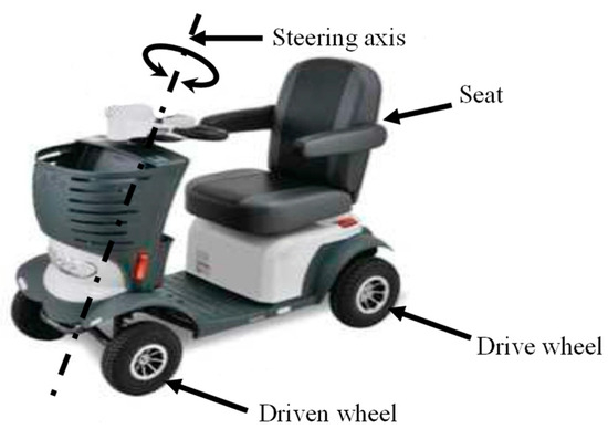
Figure 1.
Bar-handle-type electric wheelchair.
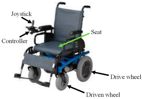
Figure 2.
Joystick-type 4-wheel electric wheelchair.
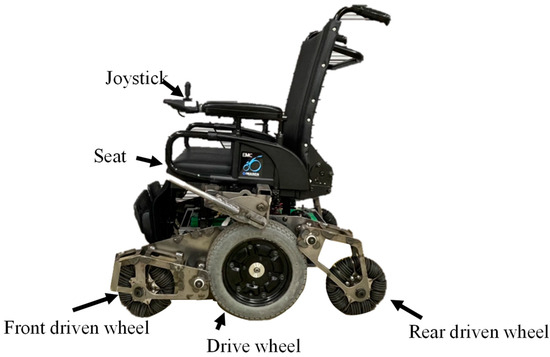
Figure 3.
Joystick-type 6-wheel electric wheelchair.
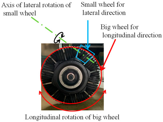
Figure 4.
Omniwheel for a joystick-type electric wheelchair’s driven wheels. It consists of a wheel that moves forward and backward and small wheels that also rotate left and right.
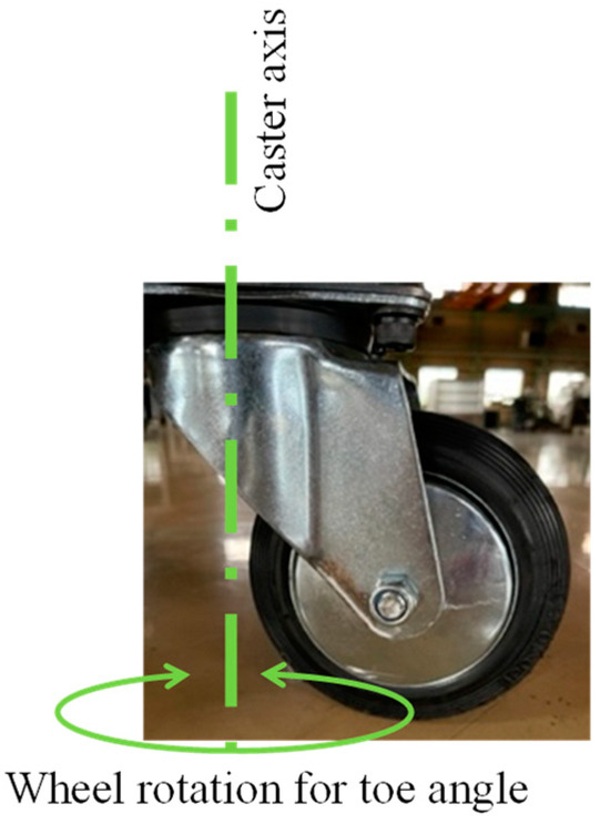
Figure 5.
Caster wheels for a joystick-type electric wheelchair’s driven wheels.
Figure 3 shows a six-wheel joystick wheelchair. In a six-wheel joystick wheelchair, the left and right center wheels provide the propulsion. In this system, the left and right center wheels can rotate in opposite directions to perform pivot turns, so it can turn in a smaller area than wheelchairs with other systems. This is shown in Figure 6. Figure 6 is a top view showing the minimum turning radius of the handle-type, four-wheel joystick, and six-wheel joystick wheelchairs. All three are drawn with the same overall length and width, but it can be seen that the six-wheel type, which rotates around the center of the vehicle dimensions, can turn in a smaller area.
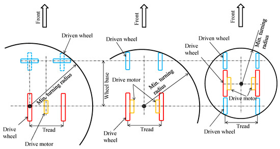
Figure 6.
A plan view comparison of the minimum turning radius of each type. The six-wheel type with the center of rotation in the middle has the greatest maneuverability.
Many commercially available joystick-type six-wheel electric wheelchairs only have a drive motor on the central wheel in the side view, due to cost considerations. Therefore, it is necessary to apply a large load to the central wheel that provides the braking and driving force. There are various types of joystick-type six-wheel electric wheelchairs, with different suspension methods to meet such purposes. Examples are shown below. Figure 7 shows an example of a chassis with three toggle links. The front wheels and the center wheel are connected by a rocker link, and the left and right rear wheels are also connected by a rocker link. Figure 8 shows an example of a chassis with two rocker links and an H-shaped link suspended by a coil spring.
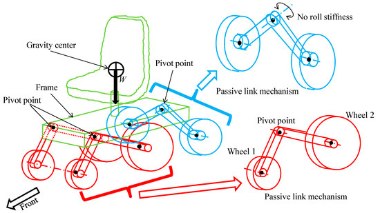
Figure 7.
Chassis with three passive links.
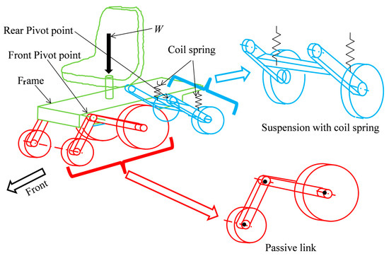
Figure 8.
Chassis consisting of two passive links and one H-link.
The transfer of wheel load from the center of gravity to the wheels in the two examples of power wheelchairs above is shown in Figure 9. The path from the center of gravity to the front and center wheels is completely separate from the path from the center of gravity to the rear wheels. Therefore, to increase the wheel load distribution to the center wheels, dimension c is set to be larger than d. Therefore, an electric wheelchair with dimensions c and d set so that c > d will have a wheel load distribution as shown in Figure 10 when driving downhill with a not too large forward tilt angle. In a wheelchair with a dimensional ratio of c > d, as shown in Figure 10, the line drawn vertically from the center of gravity to the ground points forward of the front pivot point PF. This makes the load on the rear wheel pivot point PR negative. This causes the rear wheel spring to expand, increasing the forward lean angle of the vehicle and increasing the risk of tipping forward.
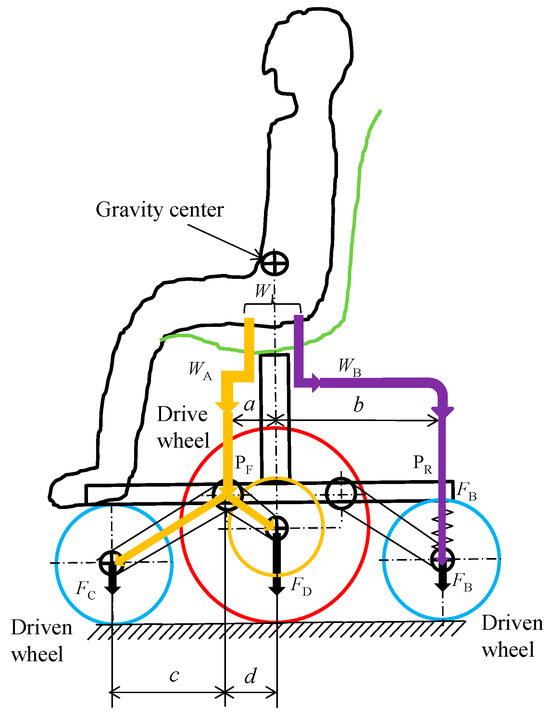
Figure 9.
Wheel load on each wheel in a conventional chassis. To increase the wheel load on the center wheel, c > d is set.
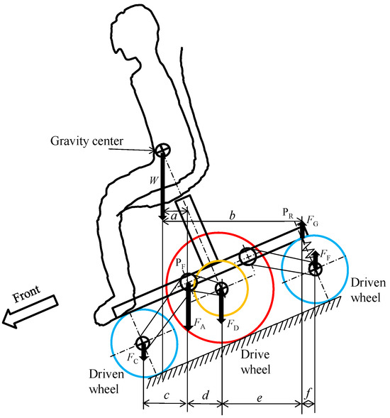
Figure 10.
A diagram showing the wheel load distribution of a conventional joystick-type six-wheel electric wheelchair on a front ramp.
This paper investigates the ability to overcome curb climbing, but in joystick-type electric wheelchairs, the contact resistance of the two front wheels with steps, etc., is input with a time lag between the left and right wheels, or there is a difference in the contact resistance of the left and right wheels, causing the vehicle to deflect to the left and right. This causes a sudden change in the yaw angle in a short period of time.
There are two possible causes of this phenomenon. One is a rotational moment about the Z-axis caused by the contact resistance generated when one of the front wheels hits an obstacle. The yaw motion moves to the side with the greater contact resistance. The other is due to the “speed x torque” characteristic of the drive motor that occurs when the front wheel hits an obstacle. The operation of the motor to restore the drive wheel speed, which has been reduced by the contact resistance of the obstacle, creates a torque difference between the left and right drive wheels. Therefore, after passing the obstacle, a yaw motion occurs in the opposite direction to the one mentioned above. These two yaw motions occur as a set in a short period of time, which is uncomfortable for the occupant.
Specific actions to address the above issues and their impact are currently under consideration and will be detailed in the next report. Here are the points under consideration. (1) One possible method is to reduce the impact force when hitting a step by lowering the front and rear support stiffness of the front wheel according to the front and rear input of the front wheel. (2) A possible method is to determine the step from the rotational speed of the engine and the yaw angle of the wheelchair, and to enable control to reduce the difference in rotational speed between the left and right drive wheels.
3. Description of the Chassis for the Improved Joystick-Type Six-Wheel Electric Wheelchair
This chapter describes a joystick-type six-wheel electric wheelchair with an improved chassis that is currently being developed for commercialization. It has been designed with the goal of having high resistance to tipping and a high ability to overcome obstacles. Please note that the improved chassis is currently under patent application [15,16] with the assumption of commercialization, and the text provides only a qualitative description of its structure and operation and does not provide specific numerical values. Figure 11 shows the complete wheelchair and Figure 12 shows the details of the suspension system. Figure 13 shows the weight distribution of each link from a side view. Next, the mechanism of this suspension system is explained. The front wheels, which are the driven wheels, and the middle wheel, which is the driving wheel, are attached to the front rocker, shown in red. The rear wheels, which are the driven wheels, are attached to the rear rocker, shown in blue. The front and rear rocker arms are connected to share the center wheel. The structure of the link is connected to the center wheel at the PC connection point, and only vertical displacement can be transmitted between them. The vertical displacement of the PC joint is transmitted by the rotating roller on the front link (red) and the U-shaped bracket on the rear link (blue). The roller is embedded in the U-shaped bracket and transmits the vertical displacement of the vehicle to each end. The relative movement of the roller and the U-bracket caused by the vertical movement of the wheel is absorbed by the roller rolling inside the U-bracket. A small gap is provided in the roller diameter and the inner width of the U-bracket to allow the roller to roll easily. The front rocker arm and the rear rocker arm are fixed to the vehicle frame so that they rotate only at the PF and PR pivots. By connecting the two front and rear rocker arms with a roller in the middle, it is possible to rotate the load of the aforementioned PR pivot point to the center wheel. In this way, it is possible to make the dimensions a and b equal and to increase their values.
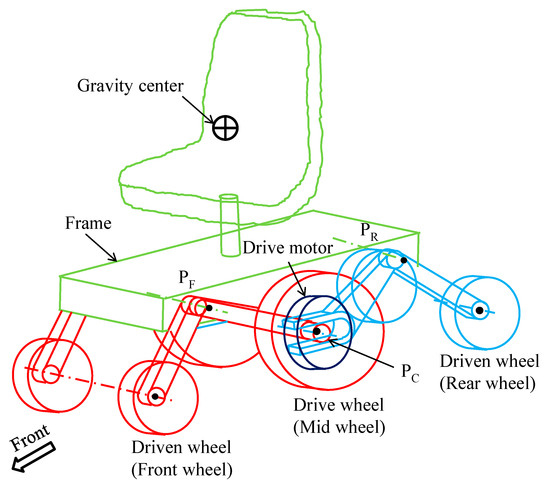
Figure 11.
Overall view of the improved chassis, which is made up of four passive links.
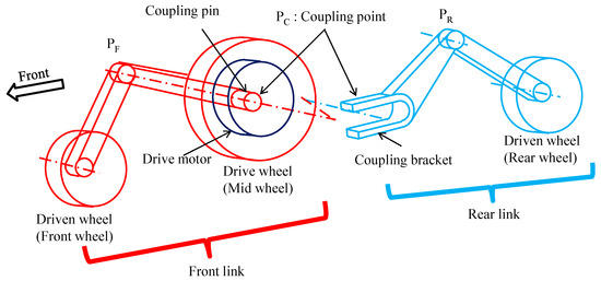
Figure 12.
Improved passive link details.
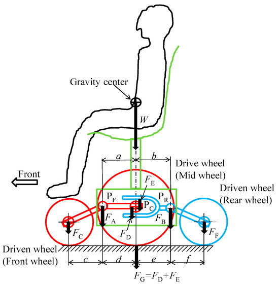
Figure 13.
Wheel load distribution mechanism for improved passive link.
Next, the weight distribution to each wheel is explained using Figure 13. The load from the center of gravity is distributed to the front pivot PF and the rear pivot PR. The load to these two pivots is distributed to FA and FB, respectively, according to the ratio of dimensions a and b. The load to the front wheel and the center wheel attached to the front rocker is distributed to FC and FD, respectively, according to the ratio of dimensions c and d. And the load to the rear wheel and the U-shaped bracket attached to the rear rocker is distributed to FE and FF, respectively, according to the ratio of dimensions e and f. The roller attached to the front rocker arm is held in the U-shaped bracket attached to the rear rocker arm. Therefore, FD and FE are added at the inner contact point PC and act on the center wheel.
In this section, we will explain wheel load distribution on uneven ground for the improved suspension system. We assume that the left front wheel, which is the drive wheel, drives over a curb as shown in Figure 14. We also assume that the height of the obstacle is such that the center of gravity shift caused by the overrun falls within the red lines formed by the points of the front and rear four-link suspensions in the top view of Figure 15.
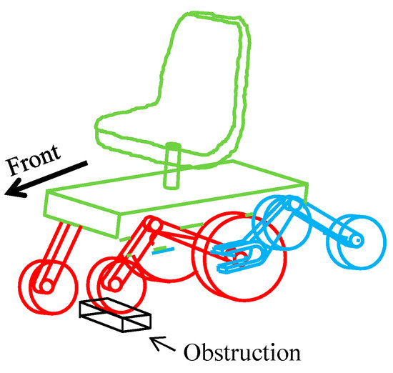
Figure 14.
One wheel running up the curb.
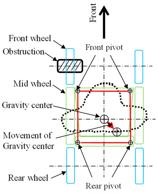
Figure 15.
Shifting the center of gravity on a plane.
Figure 16, Figure 17 and Figure 18 show the wheel loads when driving over a curb, as shown in Figure 14 and Figure 15. Figure 16 shows the wheel load distribution on the left side, where the curb is located. A downward load is generated on each wheel, as shown, and the wheels are secured in contact with the ground. Figure 17 shows the load distribution on the left and right wheels from the front of the wheelchair. As can be seen, the load is transferred to the wheel on the side without the curb. Figure 18 shows the wheel load distribution on the side without the curb, i.e., the right side. In this case, the upward displacement of the front pivot point FP that occurs on the left side lifts the right pivot point FP. This creates an upward force FA on the right pivot FP. If this force is greater than the initial front wheel load, the front wheels will lose contact with the ground. However, as shown in the figure, since the center of gravity is between the center and rear wheels, the center and rear wheels remain in contact with the ground and stable running is possible.
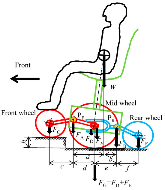
Figure 16.
Side view of wheel load distribution when driving over a curb.
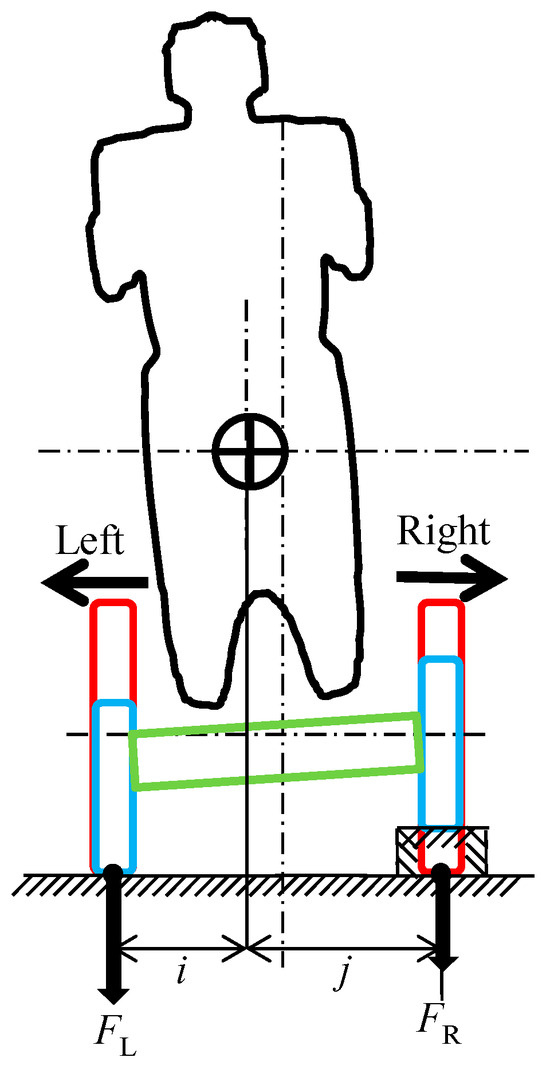
Figure 17.
Front view of wheel load distribution when driving over a curb.
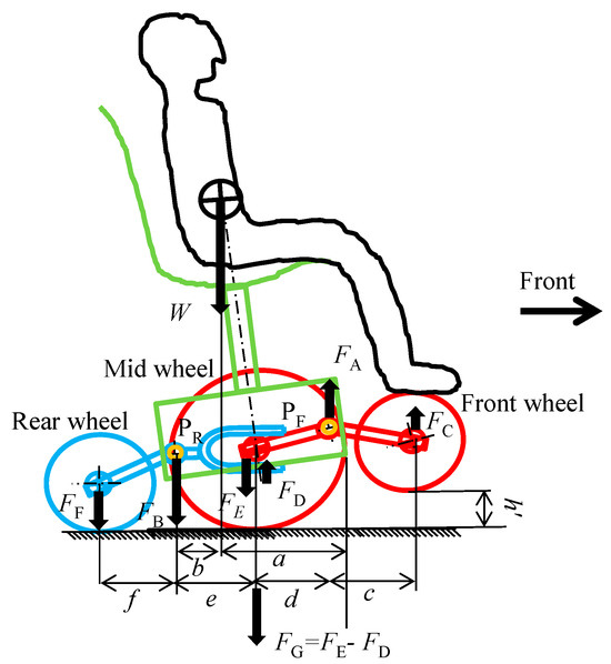
Figure 18.
Side view of wheel load distribution on the non-curb-mounted side.
Finally, we will explain the wheel load distribution on each wheel when running on a slope with the improved suspension system. Figure 19 and Figure 20 show the wheel load distribution on each wheel when running at different forward tilt angles. Figure 19 shows the state in which a line drawn vertically from the center of gravity to the ground points forward of the rear pivot PR. As can be seen from the figure, each wheel can maintain stable contact with the ground. On the other hand, Figure 19 shows the state in which the vehicle runs at a large tilt angle, where a line drawn vertically from the center of gravity to the ground points backward of the rear pivot PR. In this state, an upward force FA acts on the front pivot, causing the front wheels to lose contact with the ground.
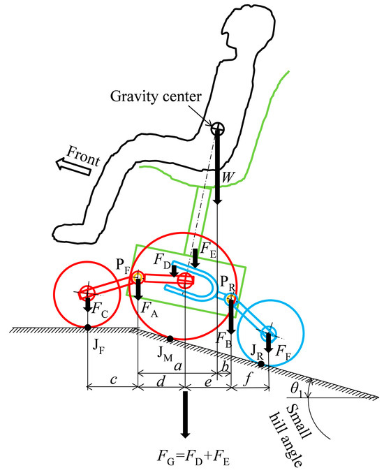
Figure 19.
Wheel load on each wheel on a small hill.
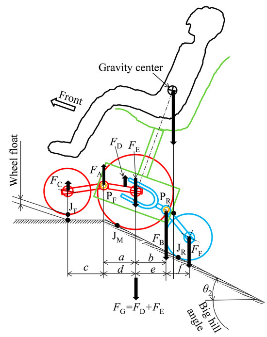
Figure 20.
Wheel load on each wheel on large climbs.
From the above, the range in which stable running is possible is expanded by the size of dimensions a and b, which are derived from the ratio of dimensions c, d, e, and f of the improved suspension system shown in Figure 13.
4. Joystick-Type Six-Wheeled Electric Wheelchair Wheel Mechanism for Climbing over Obstacles
For a joystick-type six-wheel electric wheelchair to get over a curb, the front wheels, which are the driven wheels, must get over the curb first. Then, the center wheels, which are the driven wheels, must get over the curb. It goes without saying that if the front and center wheels are successful in getting over the curb, the rear wheels will easily get over it.
4.1. Mechanism for the Driven Wheels (Front Wheels) When Passing over a Curb
First, the mechanism by which the driven wheel passes over a curb will be explained. Figure 21 shows a diagram of the driven wheel encountering a curb. The symbols in the diagram will be explained. The radius of the driven wheel is R, and the curb-climbing height is H. The forward thrust applied to the driven wheel is F, and the wheel load of the driven wheel is W. Point I indicates the wheel center, point J indicates the contact point between the ground and the wheel, and point A indicates the contact point between the curb and the wheel. Please note that the thrust F mentioned here is not only the driving force of the motor, but also includes the inertial force generated when the wheelchair encounters the curb. Furthermore, the wheel load of the driven wheel W includes not only the static front wheel load of the electric wheelchair, but also the inertial force generated by the wheelchair. Note that the driven wheel is made of hard solid rubber, so it is assumed that it does not deform.
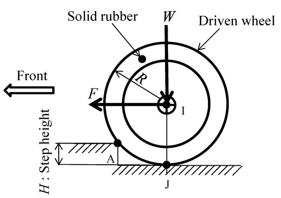
Figure 21.
Symbolic diagram of the curb-climbing mechanism of the driven wheel on the curb.
Figure 22 shows the balance of local forces that occurs when a wheel contacts point A. When a driven wheel contacts point A, a rotational moment M (shown in green) is generated that rotates point I counterclockwise around point A. This causes a diagonally forward upward force F1 to act on point I. The vertical component of F1 is FV1. Next, when the wheel with propulsive force F contacts contact point A, a force FA (shown in red) acts from point I towards point A, generating a reaction force FAO. The vertical component of this force is FV2. The sum of FV1 and FV2 is greater than the wheel load W of the driven wheel, allowing the wheel to overcome a curb climb. One way to make it easier to overcome a curb climb is to increase the difference between the tire radius R and the curb-climbing height H. Other methods include increasing the propulsive force F and reducing the wheel load W. The mechanisms described here have already been described in other studies [17,18]. Most of the previous studies on the mechanisms of wheels going over curbs have been for walking assistance devices, but there have been no studies on the passive or drive wheels of joystick-type six-wheel electric wheelchairs. Here, we proposed wheelchair specifications that can efficiently go over steps based on the curb-climbing mechanism.
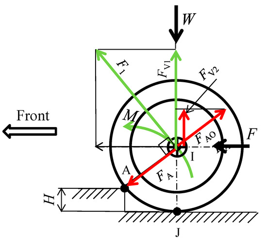
Figure 22.
Force acting on the driven wheel on the curb.
Next, let us consider F and W when the front wheel, which is the driven wheel, encounters a curb while an actual wheelchair is moving. Figure 23 shows a state in which acceleration occurs at the center of gravity when the wheelchair encounters a curb while moving. This causes a forward inertial force FB to act on the center of gravity. This, in turn, causes vertical and horizontal components FFV and FFV to act at the front wheel contact point JF. The vertical component FFV acts downward, increasing the driven wheel load W. The horizontal component F_FH is generated in the forward direction, increasing the propulsive force F.
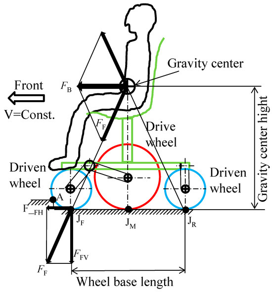
Figure 23.
Forces acting on a wheelchair due to deceleration.
From above, an increase in the driven wheel load W due to contact with a curb while moving is detrimental to getting over the curb. On the other hand, an increase in propulsive force F is advantageous for getting over the curb. In other words, it can be seen that FFH and FFV caused by a wheelchair encountering a curb have opposing effects on the ability to get over the curb. However, if the wheelbase length of a wheelchair is more than twice the height of the center of gravity, the absolute value of FFH will exceed the absolute value of FFV, and the inertial force generated when the wheelchair encounters a curb can be used to improve curb-climb-crossing performance.
Next, consider F and W when a wheelchair accelerates from a stationary state. Figure 24 shows how the force FT acting on the center of gravity when the wheelchair accelerates acts on the front wheel, which is the driven wheel. The vertical component FFV and horizontal component FFV act on the front wheel contact point JF. The vertical component FFV acts upward and reduces the wheel load W of the driven wheel. The horizontal component FFH is generated in the backward direction and reduces the propulsive force F.
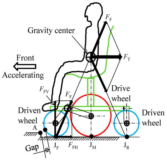
Figure 24.
Acceleration forces acting on a wheelchair.
From the above, the reduction in the wheel load W of the driven wheel due to the acceleration of the wheelchair works in favor of going over a curb. On the other hand, the reduction in the propulsive force F works against curb climbing. In other words, it can be seen that FFH and FFV generated by a wheelchair encountering a curb have opposite effects on the curb-climbing performance. However, if the wheelbase length of the wheelchair is less than half the height of the center of gravity, the absolute value of FFV will exceed the absolute value of FFH, and the inertial force generated by the wheelchair accelerating can be used to improve the curb-climbing performance. However, the relationship between the wheelbase length and the center of gravity height during acceleration in Figure 24 and during deceleration in Figure 23 is contradictory, and no dimensions exist that satisfy both.
When the dimensions c and d in Figure 13 can be set to a ratio close to 1:1, as in the improved joy-stick-type six-wheeled electric wheelchair shown in Figure 11, Figure 12 and Figure 13, the motor driving force of the center wheel affects the F and W of the driven wheels, which are the front wheels. When the dimensions c and d in Figure 13 are c > d, as in the conventional type shown in Figure 7, the effect of the driving force on F and W is small.
To explain Figure 25, the driving reaction force F1 of the motor driving wheel acting on the contact point JM acts on the pivot point PF of the front rocker link, and FM acts in the forward and upward directions. The vertical component FU of FM is divided into the front and center wheels by the inverse of the ratio of dimensions c and d, and acts on each of them. This reduces the W of the front and center wheels, which is advantageous for the front wheels’ ability to overcome curb climbing. For example, the torque of the motor is greatest at startup. Therefore, by bringing the front wheels into contact with a curb and moving forward from a stationary state with maximum acceleration force, it is possible to contribute to an improvement in the front wheels’ ability to overcome curb climbing.
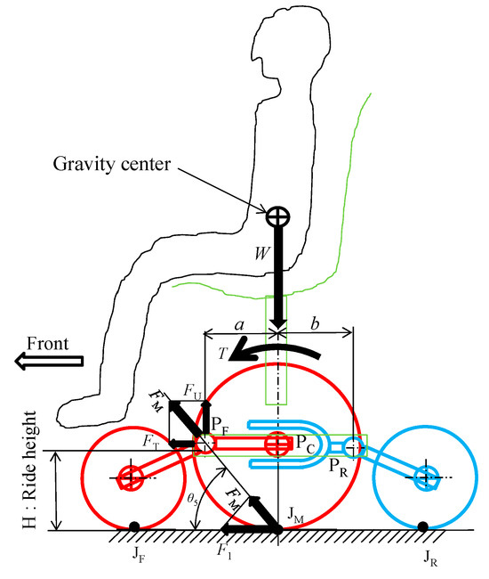
Figure 25.
Force exerted by motor drive.
4.2. Mechanism for the Drive Wheel (Center Wheel) Passing over a Curb
Here, we will examine the mechanism by which the central wheel, which is the drive wheel, passes over a curb. Figure 26 shows a diagram of when the drive wheel encounters a curb. The symbols in the diagram are explained below. The drive wheel radius is R, and the curb-climbing height is H. The forward thrust force applied to the drive wheel is F, and the drive wheel load is W. Point I indicates the wheel center, point J indicates the contact point between the ground and the wheel, and point A indicates the contact point between the curb and the wheel. The torque of the drive motor is T, and the friction coefficient between the wheel and the contact point with the curb is μ. Note that the drive wheels are pneumatic tires and so will deform under load, but here we assumed that they would not deform.
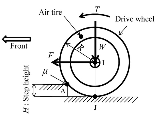
Figure 26.
Symbolic diagram of the curb-climbing mechanism of the drive wheel when curb climbing.
Figure 27 shows the balance of local forces that occur when a wheel encounters point A. Just like a driven wheel, when a wheel encounters point A, a rotational moment M (shown in green) is generated that rotates point I counterclockwise around point A. This causes a diagonal upward forward force F1 to act on point I. The vertical component of F1 is FV1. When the wheel encounters the curb, a frictional force F2 (blue) acts in the tangential direction of point A on the wheel, and the reaction force F2O acts on point I. The vertical component of this force is FV2. When the wheel encounters the curb, a force F3 (red) acts from point I towards point A, and the reaction force F3O acts on the wheel point I. The vertical component of this force is FV3. When the sum of FV1, FV2, and FV3 exceeds the driving wheel load W, the wheel will be able to overcome the curb-climbing task. To make it easier to overcome a curb, increase the difference between the tire radius R and the curb-climbing height H. Increasing the propulsive force F and reducing the wheel load W are ways to do this, as well as increasing the coefficient of friction μ between the wheel and the curb.
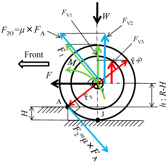
Figure 27.
Force acting on the driven wheel on the curb.
Next, we will examine the effect of the inertial force generated when the drive wheels of an electric wheelchair encounter curb-climbing when going over a curb. Figure 28 shows the change in wheel load of the drive wheels due to the inertial force F in the conventional chassis shown in Figure 8. The inertial force F indicated by the black arrow acts on the front rocker arm pivot points PF and PR directly above the coil spring. The downward force F2 indicated in green acts on the front pivot point PF, and the upward force F1 acts on the rear pivot point PR. As a result, a downward force acts on the center wheel and front wheel, increasing the wheel load W of both. In the case of the conventional type with dimension c > d, the increase in wheel load of the center wheel is significantly large, which is detrimental to going over curbs.
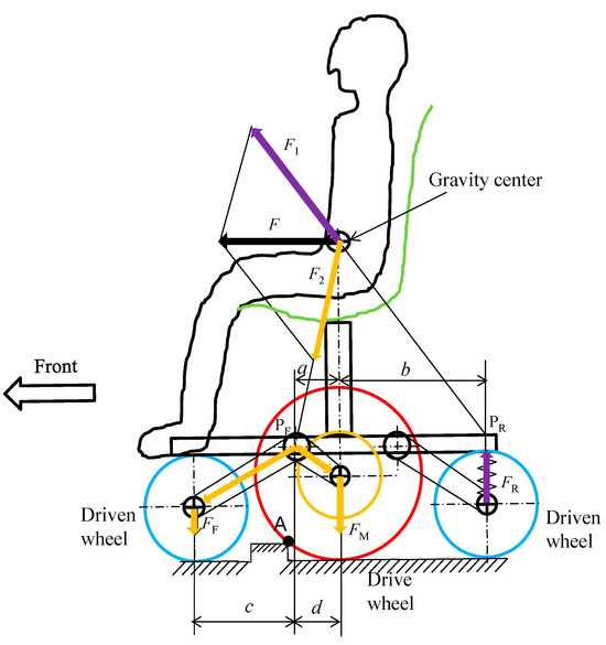
Figure 28.
Relationship between inertial force and wheel load in a conventional chassis.
Next, we considered the inertial force when the drive wheels in the improved chassis go over a curb. Figure 29 shows the change in the wheel load of the drive wheels due to the inertial force F in the improved chassis shown in Figure 11. The inertial force F indicated by the black arrow acts on the front rocker arm pivot point PF and the rear rocker arm pivot point PR. The green F2 acting on the pivot point PF acts downward on the front and center wheels. The blue F1 acting on the pivot point PR acts upward on the center and rear wheels. The center wheel receives a downward force F2M via the front and rear pivot points PF and PR, and an upward force F1M. If the dimensions in Figure 26 are a:b = 1:1, c:d:e:f = 1:1:1:1, then F1M = F2M and the wheel load of the center wheel does not change. Therefore, it is possible to set the drive wheels to go over a curb without being affected by the inertial force that occurs. Naturally, it is also possible to change the wheel load of the driving wheels by setting the dimensions a, b, c, d, e, and f.
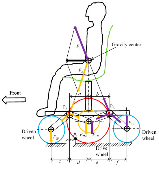
Figure 29.
Relationship between inertial force and wheel load in the improved chassis.
5. Conclusions
In this study, we investigated how the suspension of a joystick-type six-wheel electric wheelchair can improve its curb-climbing performance. We proposed a driving method suitable for curb-climbing based on the mechanism by which the front wheels (driven wheels) and middle wheels (driven wheels) climb over curbs. As a result, we discussed the possibility of improving the climbing performance by utilizing the inertial force acting on the entire wheelchair.
However, by repeating the curb-climbing tests with a prototype vehicle, we found that the impact when the front wheels hit an obstacle was large and placed a strain on the occupant. Table 1 shows the longitudinal acceleration generated in the wheelchair for each combination of electric wheelchair speed and curb height. Contact with a 30 mm curb at 2.5 km/h exceeds 0.7 G, which is a severe value for occupants with weak upper limbs.

Table 1.
Longitudinal acceleration caused by driving speed and curb height.
Based on the above, we would like to further improve the climbing performance of the wheelchair, and at the same time, conduct research and make suggestions on road environments that enable safe and secure wheelchair driving.
Author Contributions
Supervision and writing—original draft preparation, T.K. (Tetsuaki Kawata); Conceptualization, F.S.; Investigation, S.T., T.S. (Toya Suzuki), T.S. (Takato Suzuki) and T.K. (Takuto Kokuryu). All authors have read and agreed to the published version of the manuscript.
Funding
This research received no external funding.
Data Availability Statement
All authors of the papers published in this MDPI journal have already shared their research data in a university database.
Conflicts of Interest
The authors declare no conflicts of interest.
References
- Cabinet Office of Japan. 2022 White Paper on Aging Society (Full Edition). Available online: https://www8.cao.go.jp/kourei/whitepaper/w-2024/zenbun/pdf/1s1s_01.pdf (accessed on 2 June 2024).
- Statistics Bureau of Ministry of Internal Affairs and Communications of Japan. Japan’s Vital Statistics 2024. Available online: https://www.stat.go.jp/data/jinsui/new.html (accessed on 2 June 2024).
- Electric Wheelchair Safety Promotion Association of Japan. Trends in Unit Shipments 2024. Available online: https://www.den-ankyo.org/society/transition.html (accessed on 2 June 2024).
- U.S. Census Bureau. 2017 American Community Survey Single-Year Estimates. Available online: https://www.census.gov/newsroom/press-kits/2017/acs-1year.html (accessed on 2 June 2024).
- Gelau, C.; Sirek, J.; Dahmen-Zimmer, K. The effects of time pressure on older drivers’ left-turn decisions in a fixed-base driving simulator. Transp. Res. Part F Transp. Psychol. Behav. 2011, 14, 76–86. [Google Scholar] [CrossRef]
- Freund, B.; Colgrove, L.A.; Burke, B.L.; McLeod, R. Self-rated driving performance among elderly drivers referred for driving evaluation. Accid. Anal. Prev. 2005, 37, 613–618. [Google Scholar] [CrossRef] [PubMed]
- Thompson, K.R.; Johnson, A.M.; Emerson, J.L.; Dawson, J.D.; Boer, E.R.; Rizzo, M. Distracted driving in elderly and mid dleaged drivers. Accid. Anal. Prev. 2012, 45, 711–717. [Google Scholar] [CrossRef] [PubMed]
- Masuzawa, T.; Minami, S. Status and the future of electric wheel chair in Japan. Trans. J. Hum. Environ. Stud. 2010, 8, 45–53. (In Japanese) [Google Scholar]
- National Police Agency of Japan 2023. Driver’s License Statistics. Available online: https://www.npa.go.jp/publications/statistics/koutsuu/menkyo.html (accessed on 2 June 2024).
- Ishikawa, K. Study on Physical Safety and Protection at the Time of Falling over and Collision of a Wheelchair. Ph.D. Thesis, The Saitama Institute of Technology, Saitama, Japan, 2019; pp. 30–43. (In Japanese). [Google Scholar]
- Sato, Y. Safety-Conscious Electric Wheelchair; Ministry of Health, Labor and Welfare Research and Development Project for Independence Support Equipment for Persons with Disabilities: 2010. Available online: https://www.mhlw.go.jp/bunya/shougaihoken/cyousajigyou/jiritsushien_project/seika/S08Report/S08Report_01.pdf (accessed on 7 November 2023).
- Kaede, K.; Utsugi, M.; Watanuki, K.; Muramatsu, K. Estimation of driving environment with mental strain using operation of mobility scooter. Trans. JSME 2020, 86, 20–00162. (In Japanese) [Google Scholar] [CrossRef]
- Fujikawa, T.; Wang, S.; Shen, B. Development of more compact Omni-directional wheel. In Proceedings of the Transactions of Biomedical Fuzzy Systems Association, BMFSA2016, Kochi, India, 26–27 November 2016. [Google Scholar]
- Kawata, T.; Fuji World. 6-wheel electric wheelchair suspension system. Application number notification patent request 2023-7205, 20 January 2023. [Google Scholar]
- Kawata, T. Research on commercially electric wheelchairs and improving the running performance of passive link of joystick-type 6-wheel electric wheelchairs on uphill and downhill roads Part 1. Trans. JSME 2024, 90, 23–0024. (In Japanese) [Google Scholar] [CrossRef]
- Ichikawa, M. The ABC’s of Wheeled Vehicle I, Dynamics of Wheeled Vehicle. Trans. Robot. Soc. Jpn. 1995; 13, 213–218. (In Japanese) [Google Scholar]
- Nishikawa, Y.; Suzuki, Y.; Development of Level Difference Clearing Caster. Tokyo Metropolitan Industrial Technology Research Center Research Report, No. 10. 2015. Available online: https://www.iri-tokyo.jp/uploaded/attachment/1175.pdf (accessed on 7 November 2023).
- Takami, M.; The Relationship between the Wheel Shape and the Operating Force Required for a Walking Aid to Overcome Road Bumps. Kobe Gakuin Comprehensive Rehabilitation Research, Volume 11, No. 2, March 2016. Available online: https://www.reha.kobegakuin.ac.jp/~rehgakai/journal/files/no11-2/ronbun08.pdf (accessed on 7 November 2023).
Disclaimer/Publisher’s Note: The statements, opinions and data contained in all publications are solely those of the individual author(s) and contributor(s) and not of MDPI and/or the editor(s). MDPI and/or the editor(s) disclaim responsibility for any injury to people or property resulting from any ideas, methods, instructions or products referred to in the content. |
© 2024 by the authors. Licensee MDPI, Basel, Switzerland. This article is an open access article distributed under the terms and conditions of the Creative Commons Attribution (CC BY) license (https://creativecommons.org/licenses/by/4.0/).