Abstract
To enhance the static and dynamic performance of the grinding wheel spindle system, with the gear grinding machine (YKF2060) as the research object, a static mechanics model of the spindle system was established based on Castigliano’s theorem, taking into account the equivalent effect of the triple-point contact ball bearing at the front end of the spindle. Meanwhile, based on the overall transfer matrix method, a dynamic model of the main spindle–eccentric shaft dual-rotor system was established, taking into account the effects of shear deformation and gyroscopic moments. On this basis, the effect of the spindle span, the front and rear overhang of the eccentric shaft, and the bearing stiffness on the static stiffness and first-order critical speed of the system was analyzed. Finally, static stiffness experiments, modal tests, and finite element simulation models were conducted to verify the static and dynamic models. The results show that the stiffness of the front outer bearing has the greatest influence on the static and dynamic performance of the system, while the stiffness of the rear inner bearing has the least influence. The relative errors of the static stiffness and the first two natural frequencies between static stiffness experiments, modal tests, and finite element simulation models are less than 10%, and the mode shapes match well. The established static and dynamic model can effectively reflect both the static and dynamic characteristics of the spindle system.
1. Introduction
Spiral bevel gears are widely used in important fields such as automotive, aerospace, and marine fields due to their high degree of overlap, high load capacity, and low transmission noise [1,2,3]. Thereby, high-performance CNC milling and grinding machines for processing spiral bevel gears are gaining increasing attention and interest from both practitioners and academicians in various fields. The spindle system, as one of the core components of CNC machine tools, directly affects the machining accuracy, stability, and efficiency of the workpieces [4]. Hence, the establishment of a dynamic model that reflects the actual conditions of the machine tool’s spindle system is crucial for the design and optimization of machine tools.
The main evaluation index of static performance is static stiffness, which reflects the spindle system’s ability to resist static external loads. Meanwhile, the main evaluation indexes of dynamic performance include frequency response, damping characteristics, and interference resistance. In this paper, the static stiffness, natural frequency, mode shapes, and critical rotational speed were adapted to analyze the static and dynamic characteristics of the dual-rotor system. Traditional spindle rotor dynamics modeling methods mainly include the finite element method (FEM) and the transfer matrix method [5,6]. The FEM has a high calculation accuracy and is suitable for calculating dynamic systems with complex geometries, but has the drawbacks of having large memory occupation and slow computation speed [7,8,9,10]. In contrast, the transfer matrix method does not change the matrix order with the number of divided elements, making it particularly suitable for calculating chain-like systems such as spindle rotors, with advantages such as fast computation speed and ease of programming [11,12,13,14,15,16].
According to the number of rotors, rotor systems can be classified into single-rotor systems and multi-rotor systems. There is already extensive research on the dynamics of single-rotor systems. For instance, Jiang et al. [17,18] established a dynamic model of the spindle-bearing system based on the overall transfer matrix method, and studied the influence of bearing parameters, spindle inner diameter parameters, and bearing spindle assembly parameters on the dynamic characteristics of the spindle. Li et al. [19,20,21] established a comprehensive dynamic thermal–mechanical model by integrating the rotor dynamics model and thermal model of bearings, and studied the influence of bearing structure parameters on the thermo-dynamic behavior of high-speed spindles. Compared to single-rotor systems, the dynamic characteristics of multi-rotor systems are much more complex.
The dual-rotor system is the most common in multi-rotor systems. The literature survey on the dynamic analysis of spindle systems mainly focuses on the dual-rotor systems in aircraft engines and high-speed motorized spindle systems [4,22,23,24,25]. However, there is relatively little research on the spindle systems of spiral bevel gear machines, especially on the spindle system of dual-rotor gear grinding machines [26,27]. Therefore, this work focuses on the grinding wheel spindle dual-rotor system of the spiral bevel gear grinding machine (YKF2060, Hunan ZDCY CNC Equipment Co., Ltd., Changsha, China). The static and dynamic model of the spindle system was established to study the influence of the main design parameters on the static and dynamic performance of the spindle system. Static stiffness measurement experiments, modal experiments, and the FEM were designed to verify the model’s reliability, aiming to improve the static and dynamic performance of the spindle system.
2. Materials and Methods
2.1. Static Stiffness Model of the Spindle System
2.1.1. Analysis of the Spindle Box Structure of the Spiral Bevel Gear Grinding Machine
As shown in Figure 1, due to the complex curved surface of the spiral bevel gear, the structure and processing technology of the spiral bevel gear grinding machine are much more complex than those of ordinary grinding machines.
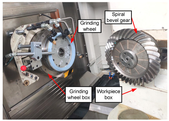
Figure 1.
Processing site of spiral bevel gear grinding machine.
The spindle system of this grinding machine adopts a dual-rotor structure, including a rotating spindle shaft and an eccentric spindle shaft, referred to as the spindle shaft and the eccentric shaft, respectively. Both are installed in the outermost shaft sleeve, supported by triple-angular-contact ball bearings at the front end and paired angular contact ball bearings at the rear end. The structure of the grinding wheel spindle box is shown in Figure 2.
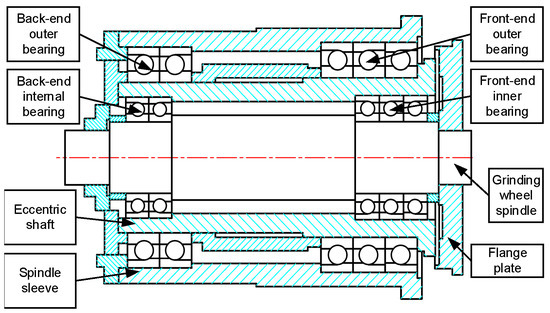
Figure 2.
Structure diagram of grinding wheel spindle box.
2.1.2. The Establishment of the Static Mechanics Model of the Spindle System
The static stiffness of the spindle system mainly refers to the static stiffness at the mounting flange of the spindle shaft, which is the main part of the spindle shaft where the grinding force acts on. According to the Hertzian contact theory, the deformations of the contact bodies are small, and the stress–strain relationship is linear and satisfies the principle of superposition. Under small deformation conditions, based on the superposition principle, the deformation of the spindle shaft can generally be divided into two parts: the bending deformation of the spindle shaft itself and the rigid body displacement of the spindle shaft caused by the bearing compression. Therefore, the total deformation of the spindle system can be approximately equal to the sum of the bending deformation and the rigid body displacement of the spindle shaft. The bearing is simplified as a spring, and the equivalent simplification of the bearing position is shown in Figure 3, according to the equivalent method.
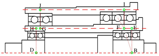
Figure 3.
Schematic diagram of simplified position of force point of triple-angular-contact ball bearing.
Since the sleeve is fixed on the machine tool, the deformation of the sleeve is not considered. The static mechanics model is established as shown in Figure 4, where points P and C are the theoretical rigid body displacement fixed points of the eccentric shaft and the spindle shaft when the spring deforms.
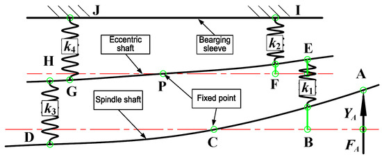
Figure 4.
Force and deformation diagram of spindle system.
Since the deformation is small, the change in the direction of the force due to the deflection of the spindle shaft can be ignored. The force balance analysis of the spindle and the eccentric shaft yields the reaction forces F of each spring in Equation (1):
Based on the bearing stiffness k, the deformation x of each bearing can be calculated, and then the rigid body displacement hE of point E can be calculated as follows:
According to Castigliano’s theorem, the bending deformation yE of point E of the eccentric shaft can be calculated as follows:
Similarly, the rigid body displacement hA and bending deformation yA of point A can be calculated as follows:
In summary, the total deformation YA of point A and the static stiffness KA can be obtained:
2.2. Dynamic Model of the Spindle System
2.2.1. Overall Transfer Matrix Method
The dynamic model of the spindle–eccentric shaft system is established based on the overall transfer matrix method, in which the bearing is simplified as a tensile spring and a torsional spring. The flange and spindle bolt connections are treated as rigid connections and simplified as a rigid disk. To make the spindle and eccentric shaft have the same number of elements, virtual elements with zero mass and zero shaft segment length are added at corresponding positions, as shown in Figure 5.
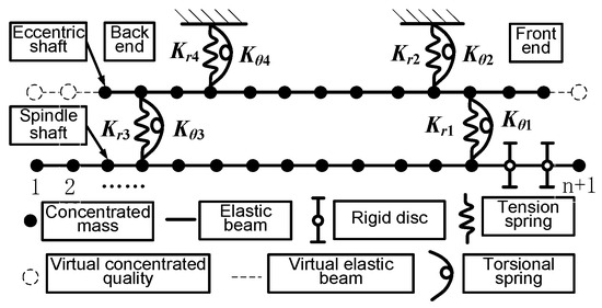
Figure 5.
Mass model of transfer matrix set for spindle system.
In Figure 5, the dual-rotor system is composed of multiple concentrated masses, elastic beam segments, and bearing springs. A typical transfer unit is shown in Figure 6. By analyzing the transfer relationships on either side of this unit and combining multiple such units, the transfer characteristics of the entire system can be obtained. This is done by defining the state variables of the shaft segment as the displacement in the direction of the plumb line y, the cross-sectional angle θ, the cross-sectional bending moment M, and the shear force Q. The state vectors of the spindle shaft S and the eccentric shaft E (ZS and ZE, respectively) can be calculated as follows:
where Zi is the state vector of the i-th shaft segment.
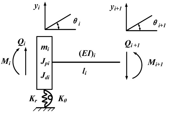
Figure 6.
Typical transfer unit.
The typical transfer unit in the system is a combination of a rigid disk (or concentrated mass) and an elastic beam, as shown in Figure 6. Considering the influence of gyro torque and shear deformation, the state transfer matrix TS of the rigid disk (or concentrated mass) and the field transfer matrix TF of the elastic beam are established in Equations (10) and (11). For incomplete elements, the corresponding parameters are set to zero.
where l is the length of the shaft segment, m is the total mass at the node, Ω is the precession angular velocity of the rotor, ω is the rotational angular velocity of the rotor, Jd is the diametral moment of inertia of the rotor, Jp is the polar moment of inertia of the rotor, EI is the bending stiffness of the shaft segment, and , G is the shear modulus of elasticity, A is the cross-sectional area of the shaft segment, and Kt is the cross-sectional shape coefficient, which is 2/3 for hollow circular sections and 0.886 for solid circular sections. Kr and Kθ are the equivalent radial and angular stiffness of the multi-row bearing, respectively.
The transfer relationship of adjacent overall elements is obtained from the typical elements:
where Ti is the transfer matrix of the i-th overall element, and , , . US and UE represent the typical unit transfer matrices of the spindle and eccentric shafts, respectively.
2.2.2. Coupling Matrix
For concentrated mass units connected by bearings, considering the bearing effect, the force relationship is shown in Figure 7. Note that the subscript i represents the i-th mass unit, the superscript S represents the main axis, E represents the eccentric axis, L represents the left side of the mass unit, and R represents the right side of the mass unit.
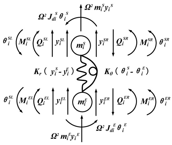
Figure 7.
Force relation of mass unit in coupling concentration.
According to Newton’s second law, the force balance of the concentrated mass of the spindle and eccentric shaft yields their respective coordination equations.
Spindle shaft S:
Eccentric shaft E:
According to Equations (13) and (14), the transfer relationship of the coupling unit is obtained, expressed as
where Ci is the coupling matrix of the i-th unit, Ui is the unit transfer matrix of the i-th typical transfer unit (as shown in Figure 6).
2.2.3. Critical Speed and Mode Shape
According to whether the overall elements are coupled or not, the total transfer matrix T and the transfer relationship of the system are obtained from Equations (12) and (15):
Both ends of the system are free ends, so the boundary conditions can be obtained as follows:
Substituting the boundary conditions into Equation (18), the characteristic determinant, with respect to Ω, can be calculated as follows:
To obtain the critical speed during synchronous precession (Ω = ω), an iterative solving process is conducted by combining the step-by-step scanning method and the bisection method. The obtained critical speed is substituted back into Equation (18) to obtain the transfer relationship between any elements. By setting the state vector of the initial element to 1, the state vector of the entire system can be obtained, and the mode shape at the corresponding speed can be obtained.
3. Results and Discussion
3.1. An Analysis of the Structural Parameters Affecting the Static and Dynamic Performance of the System
The static and dynamic performance of the system are determined by the reasonable matching of various design parameters of the dual-rotor system. Understanding the influence of each parameter on system performance is crucial for structural design and optimization. In this study, the influence of the bearing span, the front and rear overhang amount, and the bearing stiffness on the static and dynamic performance of the system is analyzed.
3.1.1. Overhang and Bearing Span
For a dual-rotor system, the eccentric shaft is similar to the spindle shaft and also has front and rear overhang and span. The bearing span of the spindle shaft lBD is equal to the sum of the front overhang lEF, the rear overhang lGH, and the span lFG of the eccentric shaft, as shown in Figure 4. Therefore, when studying the front (rear) overhang amount of the eccentric shaft, the ratio of the main shaft span to the rear (front) overhang of the eccentric shaft remains unchanged. When studying the main shaft span, the ratio of the front and rear overhang of the eccentric shaft remains unchanged. The analysis results are shown in Figure 8 and Figure 9.
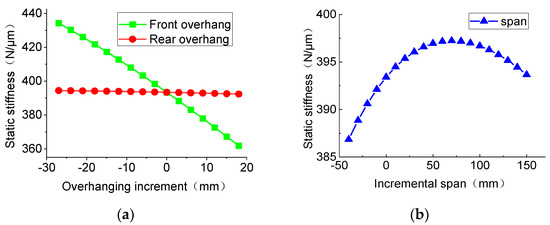
Figure 8.
Influence of suspension and span on static stiffness: (a) eccentric shaft overhang; (b) spindle span.
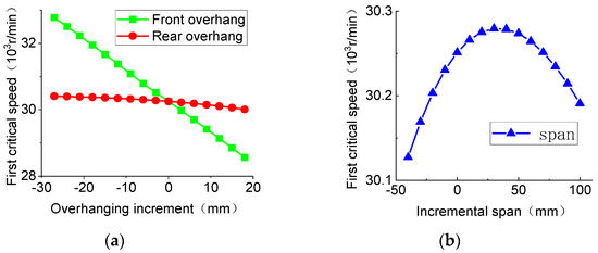
Figure 9.
Influence of suspension and span on first-order critical speed: (a) eccentric shaft overhang; (b) spindle span.
From Figure 8 and Figure 9, the influence of the three parameters on static stiffness and first-order critical speed is consistent. Among them, the front overhang has the most significant impact on both. The optimal spindle shaft bearing span increment for static stiffness and first-order critical speed are different, being 70 mm and 30 mm, respectively.
3.1.2. Bearing Stiffness
By keeping other parameters unchanged while changing the radial stiffness of the four sets of bearings in the system, ranging from half to twice the original stiffness value, the static stiffness and first-order critical speed can be obtained as shown in Figure 10 and Figure 11. From the perspective of the front and rear bearings, the stiffness of the front bearings has a greater influence on the static and dynamic performance of the system, increasing rapidly at first and then leveling off. The influence of the outer bearing stiffness is slightly greater than that of the inner bearing stiffness. The stiffness of the front outer bearing has the greatest influence on the static and dynamic performance of the system, while the stiffness of the rear inner bearing has the least influence. Therefore, the design optimization should focus on the stiffness and installation position of the front outer bearing.
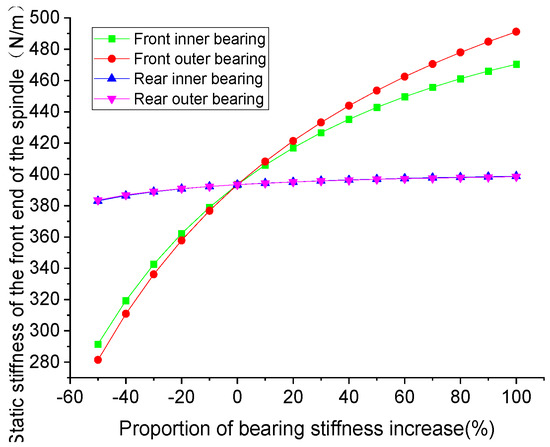
Figure 10.
Influence of bearing stiffness on static stiffness.
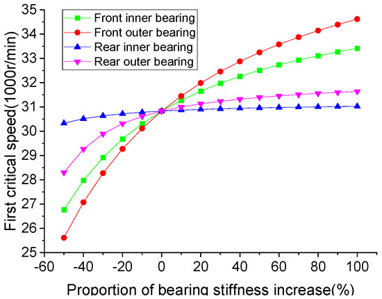
Figure 11.
Influence of bearing stiffness on first-order critical speed.
3.2. Experiments and Verification
3.2.1. Static Stiffness Measurement
To verify the effectiveness of the static stiffness model, two sets of static stiffness measurement experiments were designed: one to measure the static stiffness of the spindle–eccentric shaft assembly (or two-shaft assembly), and the other to measure the static stiffness of the three-shaft assembly after installing the bearing sleeve. The two-shaft measurement also includes static stiffness testing at both the front and rear ends, as well as static stiffness testing with light and medium preload levels for the front-end internal bearings.
The static stiffness measurement scheme of the three-shaft assembly is shown in Figure 12. The spindle box is fixed on the V-block by the pressing plate, and a jack and pressure sensor are placed at the bottom of the flange. The jack applies force continuously, measuring the deformation of the flange in the vertical direction. The pressure value on the digital display and the deformation on the inductive displacement sensor within the linear range are recorded. The measurement is repeated four–five times, with five–six data points each time. The data points are linearly fitted and averaged to obtain the static stiffness value of the spindle shaft.
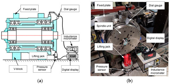
Figure 12.
Static stiffness measurement experiment: (a) schematic diagram of the experiment; (b) field diagram of the experiment.
3.2.2. Modal Test
Modal tests were conducted on the two-shaft and three-shaft assemblies measured for static stiffness to measure the dynamic characteristics of the spindle system. The modal test of the two-shaft assembly is shown in Figure 13, using the hammering method with a single-point input and a multi-point output. The spindle assembly is suspended by elastic ropes to simulate the free state of the spindle assembly. The flange is struck by a hammer, and the vertical vibration acceleration at 20 measurement points on the eccentric shaft is measured by an acceleration sensor. The modal information of the tested system is ultimately processed and analyzed through the LMS vibration testing system.
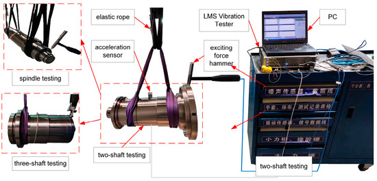
Figure 13.
Field diagram of modal test.
3.2.3. FE Simulation Model Based on Bushing Element
Since the internal spindle’s mode shape cannot be obtained in the modal test, a corresponding FE simulation model is established in ANSYS Workbench 15.0 to assist in verification. The spindle box model is imported into the model module, and the corresponding material properties are added. The bearings are usually simulated with four or more spring elements, but using the bushing element to simulate the bearing’s effect also achieves good simulation results and is simpler to set up. An FE model of the static stiffness measurement experiment is also established to further verify the reliability of the bushing element set up, as shown in Figure 14.
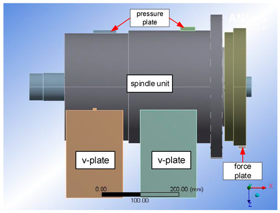
Figure 14.
Static FE simulation model.
3.2.4. Experimental Results and Analysis
The static stiffness results of the theoretical model, experiment, and FE simulation under the two conditions are shown in Table 1. Setting the precession angular velocity Ω to zero in the theoretical model can allow us to obtain the natural frequencies of the system. The first two-order natural frequencies of the theoretical model, experiment, and FE simulation are shown in Table 2. The first-order mode shapes of the two-shaft and three-shaft assemblies are shown in Figure 15 and Figure 16.

Table 1.
Comparison results of static stiffness.
Table 2.
Comparison results of first-order natural frequencies.
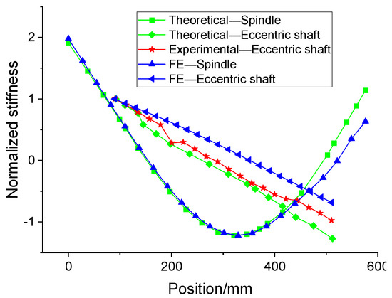
Figure 15.
First-order mode shape of two-shaft.
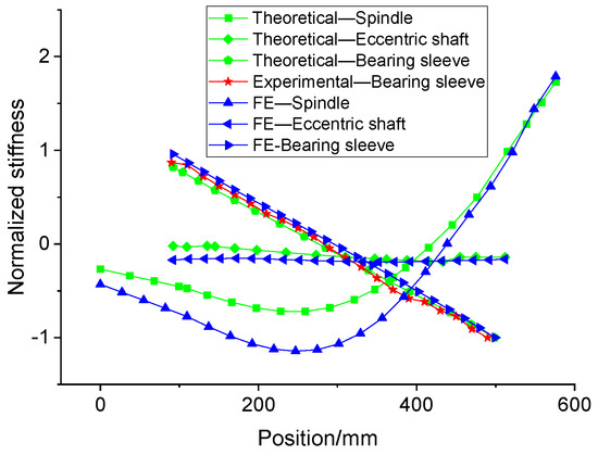
Figure 16.
First-order mode shape of three-shaft.
From Table 1, it can be seen that, regardless of the assembly form, the static stiffness values calculated from the static model are quite close to the experimentally measured values, with relative errors within 5%, thus confirming the accuracy of the static model calculations. From Table 2 and Figure 15 and Figure 16, the static stiffness and mode shapes of the theoretical model, experiment, and FE simulation for both the two-shaft and three-shaft assemblies have errors within 10%, and the mode shapes of the three are in good agreement, indicating that the static and dynamic models have good reliability. In addition, the maximum error occurs in the three-axis test. This is because the spindle–eccentric shaft-sleeve assembly cannot be suspended solely with an elastic cord, so a chain was used for suspension during the test.
4. Conclusions
In this study, the static and dynamic model of the spindle system was established to investigate the influence of the main design parameters on the static and dynamic performance of the spindle system. A summary of the important conclusions is summarized as follows:
- (1)
- Considering the static equivalent model of the triple-contact ball bearing, a static mechanics model of the double-rotor spindle system of the spiral bevel gear grinding machine is established based on Castigliano’s theorem, which can be used to calculate the static stiffness value of the spindle system. The dynamic model of the spindle–eccentric shaft system is established using the overall transfer matrix method to calculate the natural frequency, mode shape, and critical speed of the spindle system. This work fills the gap in the optimization design of the static and dynamic performance of the dual-rotor grinding machine spindle system.
- (2)
- The influence of the partial structural parameters on the static and dynamic performance of the system is analyzed. The results show that the optimal spindle bearing span for static stiffness and for first-order critical speed is different. The front overhang of the eccentric shaft has the greatest influence on the static and dynamic performance of the system. Among the four sets of bearing stiffness, the front outer bearing stiffness has the greatest influence on the static and dynamic performance of the system, while the rear inner bearing stiffness has the least influence. Therefore, the design optimization should focus on the stiffness and installation position of the front outer bearing.
- (2)
- Two sets of static mechanics experiments and modal tests are designed, and the corresponding FE simulation models are established. The comparison results show that the errors of the static stiffness and natural frequencies of the theoretical models, experiments, and FE simulation are all within 10%, and the first-order bending mode shapes are in good agreement, indicating that the theoretical models have good reliability.
Author Contributions
Conceptualization, S.H. and J.Y.; methodology, S.H.; software, J.W. and K.H.; validation, K.H.; formal analysis, S.H. and J.W.; investigation, S.H.; resources, J.Y. and J.W.; data curation, J.W.; writing—original draft preparation, S.H.; writing—review and editing, J.Y. and K.H.; visualization, J.W.; supervision, J.Y.; project administration, J.Y.; funding acquisition, J.Y. All authors have read and agreed to the published version of the manuscript.
Funding
This research was funded by the Nature Science Foundation of Changsha (No. kq2402259), the Natural Science Foundation of Hunan Province (No. 2023JJ30147), and the Post-doctoral Project of Hunan University (No. 20220643).
Data Availability Statement
Data is contained within the article.
Conflicts of Interest
The authors declare no conflicts of interest.
References
- Molaie, M.; Samani, F.S.; Zippo, A.G.; Pellicano, F. Spiral Bevel Gears: Nonlinear dynamic model based on accurate static stiffness evaluation. J. Sound Vib. 2023, 544, 117395. [Google Scholar] [CrossRef]
- Chen, P.; Wang, S.; Zou, H. Efficient semi-analytic method for single tooth contact analysis of loaded spiral bevel gears. Appl. Math. Model. 2024, 129, 754–779. [Google Scholar] [CrossRef]
- Liu, Z.; Li, F.; Xu, Z.; He, Q. Semi-analytical loaded tooth contact analysis method for spiral bevel gears. Int. J. Mech. Sci. 2023, 253, 108329. [Google Scholar] [CrossRef]
- Li, C.H.; Hou, Y.L.; Du, C.; Ding, Y.C. An analysis of the electric spindle’s dynamic characteristics of high-speed grinder. J. Adv. Manuf. Syst. 2011, 10, 159–166. [Google Scholar] [CrossRef]
- Cao, H.; Niu, L.; Xi, S.; Chen, X. Mechanical model development of rolling bearing-rotor systems: A review. Mech. Syst. Signal Process. 2018, 102, 37–58. [Google Scholar] [CrossRef]
- Lin, C.-W.; Lin, Y.-K.; Chu, C.-H. Dynamic models and design of spindle-bearing systems of machine tools: A review. Int. J. Precis. Eng. Manuf. 2013, 14, 513–521. [Google Scholar] [CrossRef]
- Xi, S.; Cao, H.; Chen, X.; Niu, L. A Dynamic Modeling Approach for Spindle Bearing System Supported by Both Angular Contact Ball Bearing and Floating Displacement Bearing. J. Manuf. Sci. Eng. 2017, 140, 021014. [Google Scholar] [CrossRef]
- Xi, S.; Cao, H.; Chen, X. Dynamic modeling of spindle bearing system and vibration response investigation. Mech. Syst. Signal Process. 2019, 114, 486–511. [Google Scholar] [CrossRef]
- Hu, T.; Yin, G.; Sun, M. Model Based Research of Dynamic Performance of Shaft-Bearing System in High-Speed Field. Shock Vib. 2014, 2014, 1–12. [Google Scholar] [CrossRef][Green Version]
- Xi, S.; Cao, H.; Chen, X.; Niu, L. Dynamic modeling of machine tool spindle bearing system and model based diagnosis of bearing fault caused by collision. Procedia CIRP 2018, 77, 614–617. [Google Scholar] [CrossRef]
- Lin, S.; Jiang, S. Dynamic characteristics of motorized spindle with tandem duplex angular contact ball bearings. J. Vib. Acoust. 2019, 141, 061004. [Google Scholar] [CrossRef]
- Wu, H.; Sang, S.; An, Q. A new vibration model for a bearing-rotor system considering a bearing structure. Proc. Inst. Mech. Eng. Part K J. Multi-Body Dyn. 2011, 225, 1–11. [Google Scholar] [CrossRef]
- Jiang, S.; Lin, S. A technical note: An ultra-high-speed motorized spindle for internal grinding of small-deep hole. Int. J. Adv. Manuf. Technol. 2018, 97, 1457–1463. [Google Scholar] [CrossRef]
- Lin, S.; Zhang, S.; Geng, K. Dynamic analysis of a high speed motorized spindle for internal grinding of slender holes. In Proceedings of the IOP Conference Series: Materials Science and Engineering, 10th International Conference on Mechatronics and Manufacturing (ICMM 2019), Bangkok, Thailand, 21–23 January 2019; p. 012013. [Google Scholar]
- Liu, J.; Lai, T.; Chen, X. Dynamics analysis of unbalanced motorized spindles supported on ball bearings. Shock Vib. 2016, 2016, 2787524. [Google Scholar] [CrossRef]
- Jiang, S.; Mao, H. Investigation of variable optimum preload for a machine tool spindle. Int. J. Mach. Tools Manuf. 2010, 50, 19–28. [Google Scholar] [CrossRef]
- Jiang, S.; Zheng, S. A modeling approach for analysis and improvement of spindle-drawbar-bearing assembly dynamics. Int. J. Mach. Tools Manuf. 2010, 50, 131–142. [Google Scholar] [CrossRef]
- Jiang, S.; Zheng, S. Dynamic design of a high-speed motorized spindle-bearing system. ASME J. Mech. Des. 2010, 132, 34501. [Google Scholar] [CrossRef]
- Li, H.; Shin, Y.C. Analysis of bearing configuration effects on high speed spindles using an integrated dynamic thermo-mechanical spindle model. Int. J. Mach. Tools Manuf. 2004, 44, 347–364. [Google Scholar] [CrossRef]
- Li, H.; Shin, Y.C. Integrated dynamic thermo-mechanical modeling of high speed spindles, part 1: Model development. J. Manuf. Sci. Eng. 2004, 126, 148–158. [Google Scholar] [CrossRef]
- Li, H.; Shin, Y.C. Integrated dynamic thermo-mechanical modeling of high speed spindles, part 2: Solution procedure and Validations. J. Manuf. Sci. Eng. 2004, 126, 159–168. [Google Scholar] [CrossRef]
- Li, Y.; Chen, X.; Zhang, P.; Zhou, J. Dynamics modeling and modal experimental study of high speed motorized spindle. J. Mech. Sci. Technol. 2017, 31, 1049–1056. [Google Scholar] [CrossRef]
- Xu, K.; Wang, B.; Zhao, Z.; Zhao, F.; Kong, X.; Wen, B. The influence of rolling bearing parameters on the nonlinear dynamic response and cutting stability of high-speed spindle systems. Mech. Syst. Signal Process. 2020, 136, 106448. [Google Scholar] [CrossRef]
- Wang, Z.; Zhu, F.L. Analysis on high-speed spindle online dynamic balancing regulation characteristics. Appl. Mech. Mater. 2017, 868, 207–211. [Google Scholar] [CrossRef]
- Hao, J.; Li, C.; Song, W.; Yao, Z.; Miao, H.; Xu, M.; Gong, X.; Lu, H.; Liu, Z. Thermal-mechanical dynamic interaction in high-speed motorized spindle considering nonlinear vibration. Int. J. Mech. Sci. 2023, 240, 107959. [Google Scholar] [CrossRef]
- Zhao, Y.; Liu, X.; Liu, M. Contact Analysis for Spiral Bevel Gear Based on Machine Parameters. In Recent Advances in Mechanisms, Transmissions and Applications: Proceedings of the Fifth MeTrApp Conference 2019; Springer: Berlin/Heidelberg, Germany, 2019; Volume 5, pp. 51–61. [Google Scholar]
- Zhiyong, W.; Weitao, D.U. Dynamics Analysis of Spindle-bearing Systems on Spiral Bevel Gear Cutting Machines. China Mech. Eng. 2019, 30, 2211–2216, 2223. [Google Scholar] [CrossRef]


Disclaimer/Publisher’s Note: The statements, opinions and data contained in all publications are solely those of the individual author(s) and contributor(s) and not of MDPI and/or the editor(s). MDPI and/or the editor(s) disclaim responsibility for any injury to people or property resulting from any ideas, methods, instructions or products referred to in the content. |
© 2024 by the authors. Licensee MDPI, Basel, Switzerland. This article is an open access article distributed under the terms and conditions of the Creative Commons Attribution (CC BY) license (https://creativecommons.org/licenses/by/4.0/).