Article

Research on Dynamic Modelling, Characteristics and Vibration Reduction Application of Hot Rolling Mills Considering the Rolling Process

1
Key Laboratory of Metallurgical Equipment and Control Technology, Ministry of Education, Wuhan University of Science and Technology, Wuhan 430081, China
2
Wuhan Iron and Steel Co., Ltd., Wuhan 430080, China
*
Author to whom correspondence should be addressed.
Machines 2024, 12(9), 629; https://doi.org/10.3390/machines12090629
Submission received: 16 August 2024 / Revised: 3 September 2024 / Accepted: 5 September 2024 / Published: 6 September 2024
(This article belongs to the Section Machine Design and Theory)

Abstract

:
The impact of rolling mill vibration extends beyond product quality to equipment health, making vibration control crucial. This study addresses the issue of frequent abnormal vibration in hot strip finishing mills by employing a combination of theory, simulation, and experimentation to analyze the dynamic behavior of the mill and apply findings to on-site vibration suppression. Initially, a torsional-vertical-horizontal coupled dynamic model for the rolling mill has been developed, taking into account the rolling process. The accuracy of this model is established through both finite element simulations and actual experiments. Subsequently, the vibration characteristics of the rolling mill system are investigated under typical process parameters utilizing the established dynamic model. The results reveal that the vibration amplitude notably escalates with the increase of rolling reduction rate and rolling speed, and the difference in front and rear tension has little impact on the mill’s vibration. Furthermore, an increase in the temperature of the rolled piece reduces the overall vibration amplitude, and harder material results in greater overall mill vibration. Lastly, abnormal vibration in the F2 finishing mill at a hot rolling plant is effectively mitigated by reducing rolling reduction rate, which further validates the correctness of the findings.

1. Introduction

As the proportion of hot-rolled thin strips increases, abnormal vibration problems frequently arise in the finishing rolling mill. This issue not only results in more equipment failures and shutdowns but also impacts product quality [1,2]. To ensure high-quality, efficient, and stable production of the production line, it is imperative to research the vibration behavior and vibration reduction methods for the rolling mills.
The rolling mill is a sophisticated mechatronic device characterized by complex coupling dynamics in its vibration patterns [3,4,5]. Abnormal vibrations in the rolling mill are influenced by various factors [6,7,8,9], including the rolling piece, the AGC hydraulic system, roll temperature, and process parameters, which frequently interact in a coupled manner.
In response to the abnormal vibration problem in rolling mills, numerous scholars have investigated the vibration mechanisms and methods for vibration reduction. The effects of different forms of fluctuations in inlet thickness, as well as hydraulic system control parameters and structural parameters on the behavior of vibrations, were analyzed by Liu et al. [10]. Chen et al. [11] investigated the random fluctuations that take place during the rolling process, revealing that noise contributed to increasing instability in the rolling mill system. Wu et al. [12] introduced a model that integrates electrical, mechanical, and hydraulic components, determining that a reduction in control gain could lead to a decrease in vibration of the rolling mill. An innovative adaptive active control strategy by Qian et al. [13] aimed at suppressing rolling mill chatter under output constraints. Yang et al. [14] created a hot rolling dynamic model utilizing the energy method, examining how vertical rolling speed and dynamic rolling force affected the dynamic performance. Wang et al. [15] utilized ANSYS software to create a multi-directional coupling model, analyzing the relation between amplitude and frequency of the rolling mill system. Xu et al. [16] developed a dynamic model for the primary transmission system in rolling mills that incorporated gear meshing. They investigated how different parameters affected the vibration characteristics of the main drive system when unsteady lubrication was present. Their findings suggested that raising the strip speed or thickness, as well as decreasing the roll radius, would result in an increase in the vibration of the main transmission system in the cold rolling mill. Jia et al. [17] discovered that the control system for thickness in rolling mills significantly affects the vibration of the mill. Their research indicated that by modifying the control system, the vibration in the rolling mill can be effectively managed.
Currently, methods employed to reduce vibration in rolling mills can be categorized into two primary strategies: changing the system’s structure and adjusting the rolling parameters. Sun et al. [18] investigated gyroscopic precession and roll eccentricity to analyze the vibration stability of four-roll cold rolling and subsequently optimized the rolling mill structure. He et al. [19] examined a rolling mill that features a dynamic vibration absorber (DVA), developed a vibration model with DVA, and evaluated the efficacy of the DVA in controlling vibrations. Wang et al. [20] designed a particle damping absorber (PDA) for vibration reduction, validating its effectiveness through theoretical modeling. Xu et al. [21] conducted additional investigations into how PDA parameters relate to the vibration in rolling mills. Meanwhile, Zhang et al. [22] developed a vertical nonlinear vibration model considering structural gaps and identified the optimal matching scheme for the coupling parameters of the structural gap and rolling force. A method was presented by Lu et al. [23] for identifying the minimum friction coefficient, utilizing mixed lubrication theory along with analysis of the friction curve characteristics. Jia et al. [24] explored the inherent features of the mill primary drive system, uncovering that modifications to both rolling and motor control parameters could influence the natural frequencies (NF), consequently reducing vibrations. A dynamic incremental model was presented by Lu et al. [25] to tackle chatter in the universal crown control rolling mill.
The investigation of vibration issues in rolling mill systems primarily focuses on vibration occurring in a single direction or the coupled vibrations in two directions. Specifically, coupled vibration generally entails the interaction of vertical-horizontal and vertical-torsional movements within the rolling mill. However, research on torsional-vertical-horizontal coupled vibration remains limited. Additionally, the connection between the parameters of the rolling process and the vibrations experienced by rolling mills has not been thoroughly investigated.
This study focuses on the F2 rolling mill within a hot rolling mill line. It considers the influences of the rolling process parameters and the structural features of hot continuous rolling mills by creating a coupled dynamic model, namely, the torsional-vertical-horizontal coupled dynamic model. Utilizing Ansys finite element software, a modal analysis of the F2 hot rolling mill was conducted, allowing for a comparison between theoretical calculations and finite element analysis results. Additionally, a rolling mill bite experiment was conducted to confirm the accuracy of the developed model for the rolling mill coupling system. By examining the vibration response of the rolling mill system model, the ways in which the rolling reduction rate, rolling piece temperature, front and rear tension difference, and rolling piece material affect the vibration amplitude are investigated. Ultimately, a practical application of vibration reduction for a rolling mill on-site was performed following the research findings, which further confirmed the validity of the conclusions of this work.
The key contributions of this work are outlined below:
  • A torsional-vertical-horizontal coupled dynamic model of a rolling mill considering the rolling process is established and validated by simulation and field experiment.
  • The influence rules of some typical parameters of the rolling process on the vibration of the rolling mill are revealed.
  • Based on the theoretical findings, an application is performed for a hot continuous finishing mill on site to suppress its vibration.
The structure of the paper is organized as follows. In Section 2, the coupled dynamic model is established and validated. In Section 3, rolling excitations, considering the rolling process and influence of typical rolling process parameters, are analyzed. An application is performed for a hot continuous finishing mill on site to suppress its vibration by adjusting the rolling process parameter in Section 4. Finally, some key conclusions are drawn in Section 5.

2. Dynamic Model Establishment and Verification

2.1. Coupled Dynamic Model

This study investigates the F2 rolling mill situated within the finishing rolling production line of a hot rolling facility. Figure 1 illustrates the structure of the rolling mill. The main transmission subsystem includes a motor, motor coupling, reducer, intermediate coupling, a herringbone gearbox, which is to make sure the rotating speed of upper and lower work roll is equal and the rotating direction is opposite, and both upper and lower connecting shafts, as well as the roller systems. The upper and lower roller systems form the horizontal subsystem, whereas the vertical subsystem consists of the rolling mill stand, hydraulic cylinder, upper and lower beams, upper and lower roller systems, as well as their respective bearings and bearing seats.
Establishing dynamic equations for complex systems often requires simplifying the system and abstracting its dynamic model. The rolling mill system is simplified by focusing on key points while disregarding unimportant details. Furthermore, by considering the interactions between the roller system and the vibrating subsystem in each direction, the model can be further refined, as demonstrated in Figure 2.
In Figure 2, θ i (i = 1~8) represents the angular displacement of the primary transmission system within the rolling mill. y z (z = 1~6) represents the displacement of vertical vibration system. x s (s = 1, 2) denotes the displacement of the horizontal vibration system. The horizontal direction means the rolling direction or the moving direction of rolled pieces.
The effective moment of inertia of the primary transmission system is indicated by J i , whereas m z and M s refer to the vertical and horizontal effective mass of the rolling mill, respectively. The symbols c i and k i stand for the effective damping and stiffness of the primary transmission system, respectively. In contrast, C z , K z , C H s , and K H s symbolize the effective damping and stiffness in both the vertical and horizontal orientations of the rolling mill. Meanwhile, K4, C 4 , K H 2 and C H 2 will all be influenced by the rolled piece. The reduction amount and temperature variations when rolled piece of different materials will result in different values. In the absence of rolled piece in the mill, both K H 2 and C H 2 are 0, while K 4 represents the elastic flattening stiffness of the upper and lower work rolls. While the rolling mill is working on the strip, K H 2 is determined by taking the horizontal force and dividing it by the projected length of the contact arc in the horizontal plane.
According to Figure 2, the kinetic energy T, potential energy U, and dissipated energy D of the coupled system are expressed as:
T = 1 2 J 1 θ ˙ 1 2 + 1 2 J 2 θ ˙ 2 2 + 1 2 J 3 θ ˙ 3 2 + 1 2 J 3 θ ˙ 3 2 + 1 2 J 4 θ ˙ 4 2 + 1 2 J 5 θ ˙ 5 2 + 1 2 J 6 θ ˙ 6 2 + 1 2 J 7 θ ˙ 7 2 + 1 2 J 8 θ ˙ 8 2 + 1 2 m 1 y ˙ 1 2 + 1 2 m 2 y ˙ 2 2 + 1 2 m 3 y ˙ 3 2 + 1 2 m 4 y ˙ 4 2 + 1 2 m 5 y ˙ 5 2 + 1 2 m 6 y ˙ 6 2 + 1 2 M 1 x ˙ 1 2 + 1 2 M 2 x ˙ 2 2
U = 1 2 k 1 ( θ 1 θ 2 ) 2 + 1 2 k 2 ( θ 2 θ 3 ) 2 + 1 2 k 3 ( θ 3 θ 4 ) 2 + 1 2 k 4 ( θ 4 θ 5 ) 2 + 1 2 k 5 ( θ 4 θ 6 ) 2 + 1 2 k 6 ( θ 5 θ 7 ) 2 + 1 2 k 7 ( θ 6 θ 8 ) 2 + 1 2 K 1 y 1 2 + 1 2 K 2 ( y 2 y 1 ) 2 + 1 2 K 3 ( y 3 y 2 ) 2 + 1 2 K 4 ( y 4 y 3 ) 2 + 1 2 K 5 ( y 5 y 4 ) 2 + 1 2 K 6 ( y 6 y 5 ) 2 + 1 2 K 7 y 6 2 + 1 2 K H 1 x 1 2 + 1 2 K H 2 ( x 1 x 2 ) 2 + 1 2 K H 3 x 2 2
D = 1 2 c 1 ( θ ˙ 1 θ ˙ 2 ) 2 + 1 2 c 2 ( θ ˙ 2 θ ˙ 3 ) 2 + 1 2 c 3 ( θ ˙ 3 θ ˙ 4 ) 2 + 1 2 c 4 ( θ ˙ 4 θ ˙ 5 ) 2 + 1 2 c 5 ( θ ˙ 4 θ ˙ 6 ) 2 + 1 2 c 6 ( θ ˙ 5 θ ˙ 7 ) 2 + 1 2 c 7 ( θ ˙ 6 θ ˙ 8 ) 2 + 1 2 C 1 y ˙ 1 2 + 1 2 C 2 ( y ˙ 2 y ˙ 1 ) 2 + 1 2 C 3 ( y ˙ 3 y ˙ 2 ) 2 + 1 2 C 4 ( y ˙ 4 y ˙ 3 ) 2 + 1 2 C 5 ( y ˙ 5 y ˙ 4 ) 2 + 1 2 C 6 ( y ˙ 6 y ˙ 5 ) 2 + 1 2 C 7 y ˙ 6 2 + 1 2 C H 1 x ˙ 1 2 + 1 2 C H 2 ( x ˙ 1 x ˙ 2 ) 2 + 1 2 C H 3 x ˙ 2 2
The equation of motion for the system is formulated using the Lagrange equation approach, as demonstrated below:
{ J 1 θ ¨ 1 + c 1 ( θ ˙ 1 θ ˙ 2 ) + k 1 ( θ 1 θ 2 ) = M R J 2 θ ¨ 2 c 1 ( θ ˙ 1 θ ˙ 2 ) + c 2 ( θ ˙ 2 θ ˙ 3 ) k 1 ( θ 1 θ 2 ) + k 2 ( θ 2 θ 3 ) = 0 J 3 θ ¨ 3 c 2 ( θ ˙ 2 θ ˙ 3 ) + c 3 ( θ ˙ 3 θ ˙ 4 ) k 2 ( θ 2 θ 3 ) + k 3 ( θ 3 θ 4 ) = 0 J 4 θ ¨ 4 c 3 ( θ ˙ 3 θ ˙ 4 ) + c 4 ( θ ˙ 4 θ ˙ 5 ) + c 5 ( θ ˙ 4 θ ˙ 6 ) k 3 ( θ 3 θ 4 ) + k 4 ( θ 4 θ 5 ) + k 5 ( θ 4 θ 6 ) = 0 J 5 θ ¨ 5 c 4 ( θ ˙ 4 θ ˙ 5 ) + c 6 ( θ ˙ 5 θ ˙ 7 ) k 4 ( θ 4 θ 5 ) + k 6 ( θ 5 θ 7 ) = 0 J 6 θ ¨ 6 c 5 ( θ ˙ 4 θ ˙ 6 ) + c 7 ( θ ˙ 6 θ ˙ 8 ) k 5 ( θ 4 θ 6 ) + k 7 ( θ 6 θ 8 ) = 0 J 7 θ ¨ 7 c 6 ( θ ˙ 5 θ ˙ 7 ) k 6 ( θ 5 θ 7 ) = M T 1 J 8 θ ¨ 8 c 7 ( θ ˙ 6 θ ˙ 8 ) k 7 ( θ 6 θ 8 ) = M T 2 m 1 y ¨ 1 + C 1 y ˙ 1 C 2 ( y ˙ 2 y ˙ 1 ) + K 1 y 1 K 2 ( y 2 y 1 ) = 0 m 2 y ¨ 2 + C 2 ( y ˙ 2 y ˙ 1 ) C 3 ( y ˙ 3 y ˙ 2 ) + K 2 ( y 2 y 1 ) K 3 ( y 3 y 2 ) = 0 m 3 y ¨ 3 + C 3 ( y ˙ 3 y ˙ 2 ) C 4 ( y ˙ 4 y ˙ 3 ) + K 3 ( y 3 y 2 ) K 4 ( y 4 y 3 ) = F 1 y m 4 y ¨ 4 + C 4 ( y ˙ 4 y ˙ 3 ) C 5 ( y ˙ 5 y ˙ 4 ) + K 4 ( y 4 y 3 ) K 5 ( y 5 y 4 ) = F 2 y m 5 y ¨ 5 + C 5 ( y ˙ 5 y ˙ 4 ) C 6 ( y ˙ 6 y ˙ 5 ) + K 5 ( y 5 y 4 ) K 6 ( y 6 y 5 ) = 0 m 6 y ¨ 6 + C 6 ( y ˙ 6 y ˙ 5 ) C 7 y ˙ 6 + K 6 ( y 6 y 5 ) K 7 y 6 = 0 M 1 x ¨ 1 + C H 1 x ˙ 1 + C H 2 ( x ˙ 1 x ˙ 2 ) + K H 1 x 1 + K H 2 ( x 1 x 2 ) = F 1 X M 2 x ¨ 2 + C H 3 x ˙ 2 C H 2 ( x ˙ 1 x ˙ 2 ) + K H 3 x 2 K H 2 ( x 1 x 2 ) = F 2 X
Equation (4) can be represented in matrix form, as demonstrated below:
[ M ] [ q ¨ ] + [ C ] [ q ˙ ] + [ K ] [ q ] = [ Q ]
The matrices [ M ] , [ K ] , [ C ] , and [ Q ] correspond to the mass, stiffness, damping, and external load of the rolling mill system, respectively. Additionally, [ q ¨ ] , [ q ˙ ] , and [ q ] correspond to the generalized acceleration, generalized velocity, and generalized displacement, respectively, which are composed of various degrees of freedom within the rolling mill coupled system. The specific forms of [ M ] , [ C ] , [ K ] , and [ Q ] are as follows:
[ M ] = diag [ J 1 , J 2 , , J 8 , m 1 , m 2 , , m 6 , M 1 , M 2 ]
[ C ] = [ Φ N T ] 1 [ C N ] [ Φ N ] 1
where [ C ] is substituted with the mode damping matrix for simplification; [ Φ N ] is the regularized mode matrix; and [ C N ] is the regularized damping matrix, which is presented as:
[ C N ] = 2 ζ d i a g [ ω 1 , ω 2 , , ω 15 , ω 16 ]
where ζ is the mode damping ratio, which is 0.06, as determined by vibration measurement of rolling mills, and ω L ( L = 1 ~ 16 ) in [ C N ] is the Lth order natural frequency of the system.
[ K ] = [ [ Z ] 0 0 0 [ Y ] 0 0 0 [ X ] ]
[ Q ] = [ M R , 0 , 0 , 0 , 0 , 0 , M T 1 , M T 2 , 0 , 0 , F 1 y , F 2 y , 0 , 0 , F 1 X , F 2 X ] T
where: M R = 2 M T 1 , M T 1 = M T 2 , F 1 y = F 2 y , F 1 X = F 2 X
[ Z ] = [ k 1 k 1 0 0 0 0 0 0 k 1 ( k 1 + k 2 ) k 2 0 0 0 0 0 0 k 2 ( k 2 + k 3 ) k 3 0 0 0 0 0 0 k 3 ( k 3 + k 4 + k 5 ) k 4 k 5 0 0 0 0 0 k 4 ( k 4 + k 6 ) 0 k 6 0 0 0 0 k 5 0 ( k 5 + k 7 ) 0 k 7 0 0 0 0 k 6 0 k 6 0 0 0 0 0 0 k 7 0 k 7 ]
[ Y ] = [ ( K 1 + K 2 ) K 2 0 0 0 0 K 2 ( K 2 + K 3 ) K 3 0 0 0 0 K 3 ( K 3 + K 4 ) K 4 0 0 0 0 K 4 ( K 4 + K 5 ) K 5 0 0 0 0 K 5 ( K 5 + K 6 ) K 6 0 0 0 0 K 6 ( K 6 + K 7 ) ]
[ X ] = [ K H 1 + K H 2 K H 2 K H 2 K H 2 + K H 3 ]
The parameters for the dynamic model of the rolling mill are outlined in Table 1. For the torsional subsystem, the moment of inertias and torsional stiffnesses are computed by material mechanics with the geometry and property of materials, considering the transmission ratio, which is 75/23 for the reducer of the rolling mill and 1 for the herringbone gearbox. For the parameters of vertical and horizontal subsystems, masses are extracted from the 3D CAD model, and the stiffnesses are calculated by the definition of stiffness with Hook’s law using the static calculation by ANSYS 2022 R2, which is to calculate the deformation under provided force.
The undamped natural frequencies (NF) of the theoretical model of the rolling mill system, without the presence of a rolled piece, are shown in Table 2.

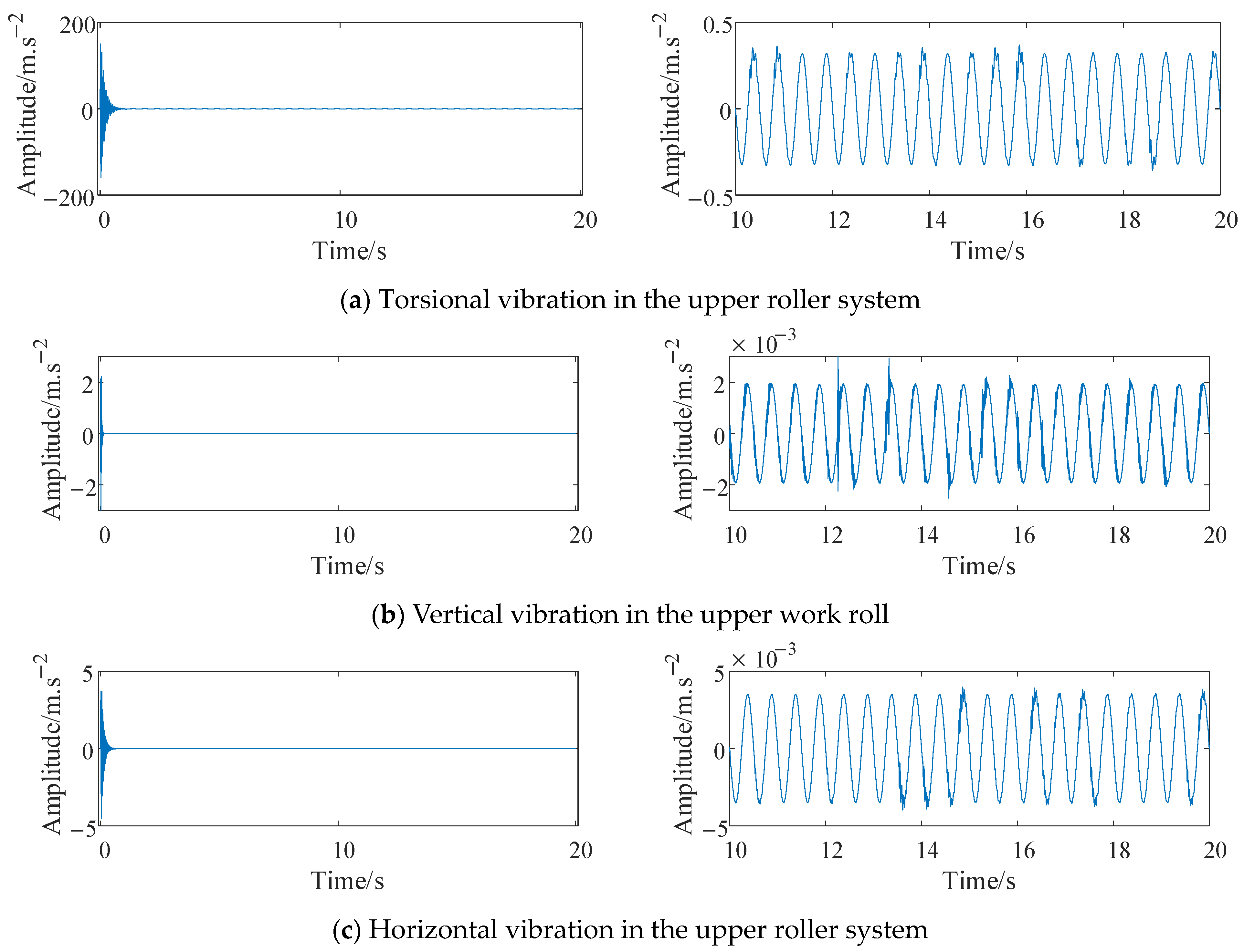
2.2. Model Verification

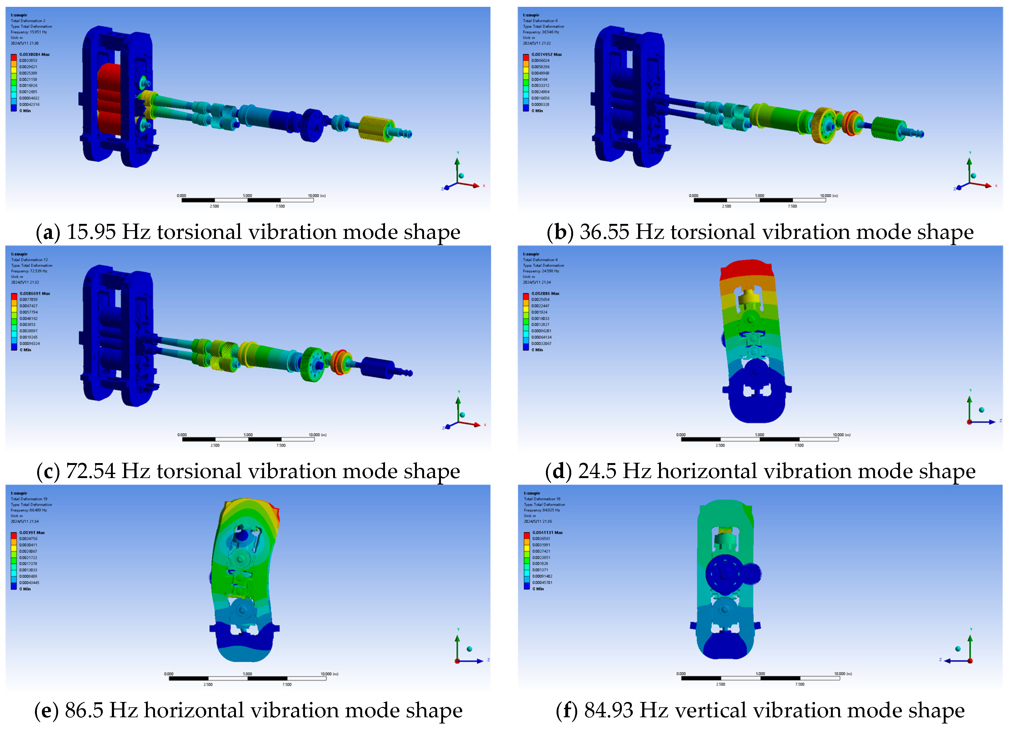
2.2.1. Finite Element Simulation Verification

The model of the rolling mill utilizes SOLID186 and SOLID187 elements for meshing. The finite element model for the F2 rolling mill is created using Ansys 2022 R2, as illustrated in Figure 3.
Fixed constraints are applied to the four anchor bolt holes of the rolling mill frame in accordance with the actual installation conditions. In the rolling mill transmission system, only axial rotation is permitted at the bearings, while all other degrees of freedom are constrained. Constraint equations are incorporated where it is necessary to reflect the transmission relationship, whereas connections that do not require such reflection are established through contact. Modal analysis is performed utilizing the Block Lanczos method.
The results from the finite element modal analysis are presented in Figure 4, and the comparison of theoretical and simulated NF results is shown in Table 3.
Table 3 illustrates that the errors in NF between theoretical calculations and finite element simulations are small, which validates the accuracy of the theoretical model. Besides, the NF associated with the torsional vibrations of the rolling mill numerically meet the required design standards for the transmission system of the rolling mill [26]; specifically, the NF of the second-order torsional vibration must be greater than double that of the first-order torsional vibration, and the NF corresponding to the n+1th order torsional vibration should be at least 1.3 times higher than that of the nth order torsional vibration (n ≥ 2).

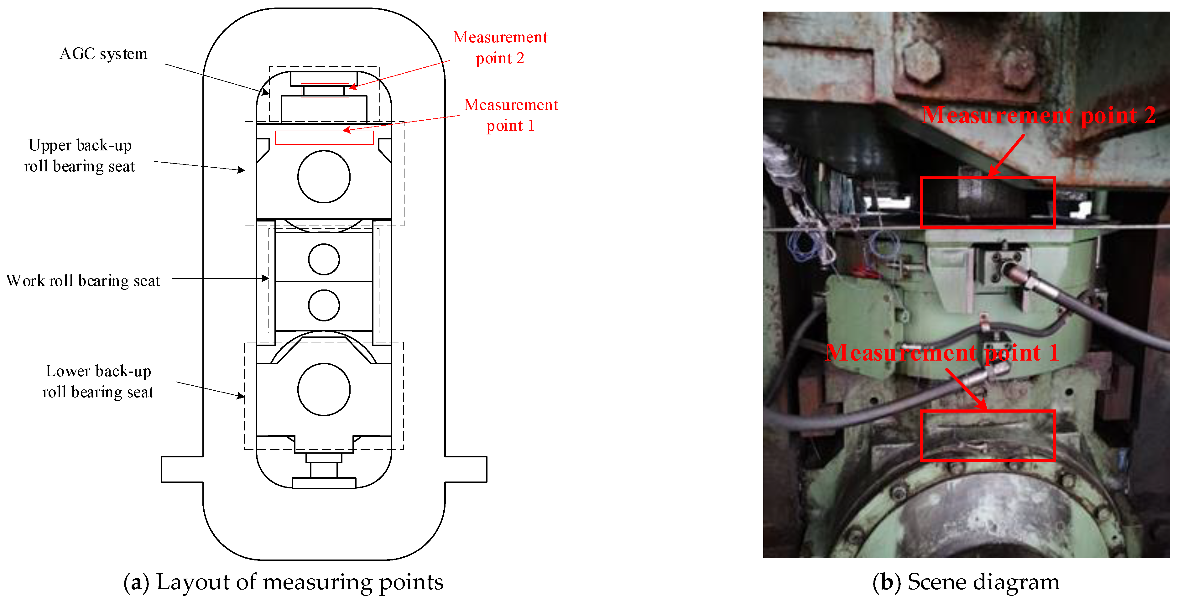
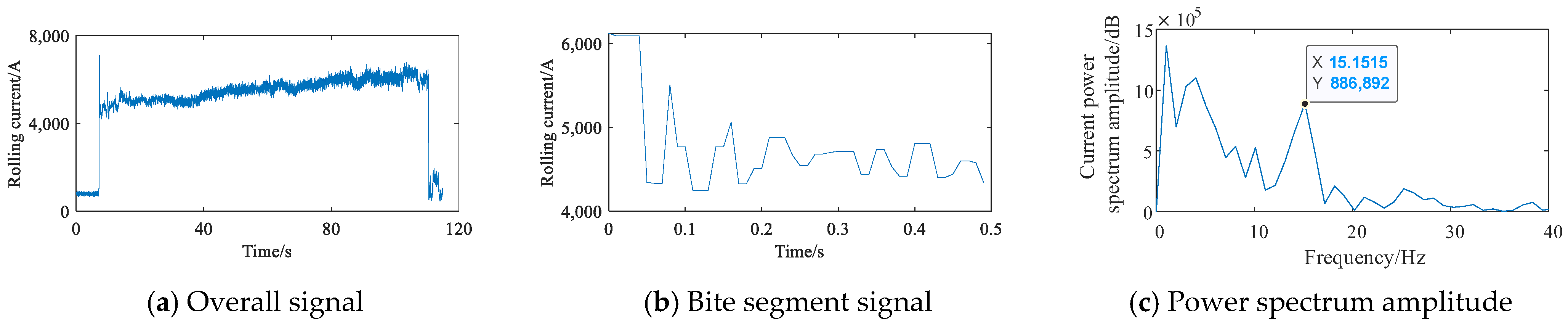
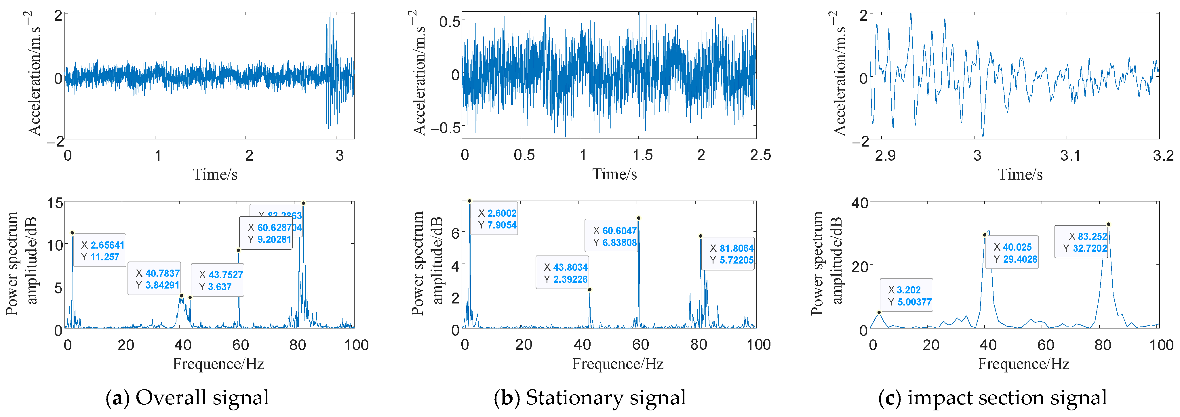
2.2.2. Experimental Verification

In order to obtain the real vibration responses, a vibration monitoring system is installed in the F2 rolling mill. Vibration acceleration sensors have been positioned on the upper plate of the AGC system as well as on the bearing seat of the support mill. This arrangement is illustrated in Figure 5. The corresponding rolling mill parameters are recorded by the PDA (Process Data Acquisition) system, which is commonly stalled by iron and steel enterprises.
To validate the established model, the real vibrations when the rolled piece is bitten into the rolling mill are utilized. The bite stage of the rolling mill can be compared to applying a step excitation to the system, leading to a vibration response that includes the system NF. By analyzing the signal spectrum during the bite phase of the rolling mill system, it is possible to determine the NF of the system, thereby validating the correctness of the theoretical model.
Figure 6 displays the bite signals and their spectrum in the horizontal, axial, and vertical directions from the vibration measuring point at the upper backup roll bearing seat. In Figure 6a, it is clear that the two peak frequencies at 15 Hz and 24 Hz pertain to the horizontal direction, indicating relevant inherent characteristics. The frequencies of 42 Hz and 91 Hz clearly correspond to the inherent characteristics of the system related to axial vibration, which can be seen from the axial bite signal spectrum, as shown in Figure 6b. In contrast, the vertical bite signal spectrum presented in Figure 6c does not reveal obvious vertical inherent characteristic information, but 15 Hz and 24 Hz, which appear in the horizontal direction, are also shown in the vertical direction, meaning that all directions are coupled with each other.
In order to determine the natural frequencies (NF) in each direction, the rolling current signal obtained from PDA is analyzed, as shown in Figure 7. Due to the limited sampling frequency of the PDA system, only a small number of impact signal points are obtained, resulting in a low signal frequency resolution. However, the peak frequency of 15 Hz is still clearly identifiable. The frequency corresponds to the natural frequency of torsional vibration in the transmission system, as the rolling current is directly related to the rolling torque. Therefore, 15 Hz is determined as the first torsional NF.
As the vertical inherent information is limited to the bearing seat measurement point, another impact signal from the embedded sensor in the reduction box is studied, which is illustrated in Figure 8. From Figure 8, it is deduced that 83 Hz could be an inherent characteristic associated with vertical vibration. It should be noted that 50 Hz and its multiple components in the signals represent power frequency interference.
Combining the experiment analysis, finite element simulation, and theoretical model calculation results, it is revealed that the first-order (excluding rigid body mode) torsional NF is 15 Hz, 24 Hz is the horizontal NF of the rolling mill system, the axial first-order NF is 42 Hz, the axial second-order NF is 91 Hz, and the vertical first-order NF of the rolling mill is 83 Hz. These results further validate the accuracy of the theoretical model and suggest that dynamic characteristic studies can be conducted based on this established model. Additionally, the experimental results indicate that the vibration in a certain direction includes the NF of vibration in other directions, demonstrating a coupling between the directions of the rolling mill.

3. Analysis of Dynamic Response of the Rolling Mill System

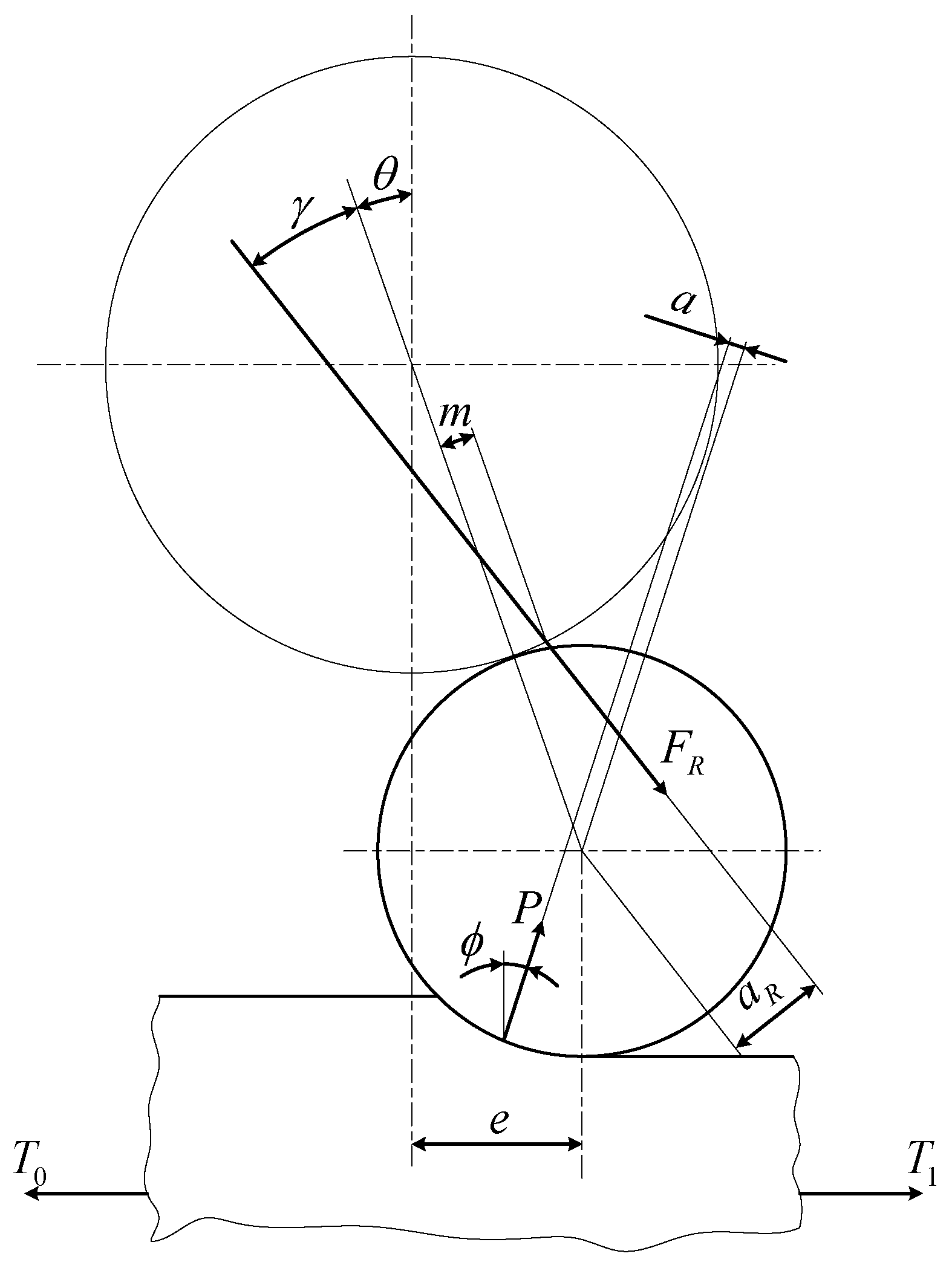
3.1. Relationship between Rolling Excitations and Rolling Process Parameters

The vibration of a rolling mill system is influenced by structural and process parameters; the former affect the system transmission characteristics and the latter affect the excitations. Key process parameters like the rate of rolling reduction, rolling speed, billet temperature, billet material, and front and rear tension are crucial. Given the challenge of altering structural parameters during operation, focusing on rolling process parameters offers a practical approach for the rolling mill vibration control on site.
The parameters of the rolling process primarily impact the vibration of the rolling mill, as they affect both the rolling torque and rolling force. Figure 9 illustrates the geometric relationship of the force system.
The expression for the rolling force P is as follows:
P = p m b l
In this formula, b represents the width of the rolled piece, l denotes the horizontal projection of the contact arc length, and p m signifies the rolling average unit pressure, which can be ascertained by the Sims method [27,28,29] following the assumption that the deformation area of the rolled piece is fully adhered. This can be accepted in the hot rolling process as the friction force per unit remains constant and equivalent to half of the metal deformation resistance. Then, p m can be presented as follows:
p m = [ 0.8 + ( 0.45 ε + 0.04 ) ( R h 0 0.5 ) ] β σ
where ε represents the relative reduction, R stands for the radius of the work roll, h 0 signifies the initial thickness of the rolled piece, and β represents the influence coefficient of the intermediate principal stress. When rolling the piece, β is considered as 1.15. σ represents the metal deformation resistance, which varies based on the type of material used for the rolled piece and deformation conditions. σ can be represented using the following formula:
σ = σ 0 e ( A + V T t e m p + 273 1000 ) ( u 10 ) C + J T t e m p + 273 1000 [ E ( r m 0.4 ) N ( E 1 ) r m 0.4 ]
In the formula, σ 0 represents the base deformation resistance, T t e m p denotes the billet temperature, u indicates the deformation speed, and r m signifies the true average deformation degree. The coefficients A , V , C , J , N, and E are the deformation resistance formula coefficients.
The torque M Q needed to operate the work roll can be represented as:
M Q = M Z + M F + M f
where M Z represents the rolling torque, M F represents the torque exerted by the work roll driving the backup roll, and M f represents the friction torque at the work roll bearing.
The rolling torque M Z can be expressed by the following formula:
M Z = P a
The rolling force arm, denoted as a , can be expressed using the following formula:
a = R sin ( 0.5 arccos ( 1 Δ h 2 R ) ϕ )
In the formula, Δ h represents the rolling reduction rate, R denotes the radius of the work roll, and ϕ indicates the deflection angle induced by the effect of tension on the rolling force, which can be articulated using the subsequent formula:
ϕ = arcsin ( T 1 T 0 2 P )
In the formula, T 1 represents the front tension, T 0 represents the back tension, and Δ T ( Δ T = T 1 T 0 ) indicates the difference between the front and rear tensions.
The torque M F exerted by the work roll on the backup roll can be represented by the formula below:
M F = F R a R
where F R denotes the reaction force exerted by the back-up roll onto the work roll and a R represents the force arm of the reaction force on the work roll.
The reaction force F R can be articulated in the following manner:
F R = P cos ( ϕ ) cos ( θ + γ )
In the formula, γ represents the angle between the center line of the roller and F R and θ indicates the angle between the center line connecting the work roll and the backup roll and the vertical line.
The calculation for angle γ can be performed using the formula below:
γ = arcsin ( R f 2 + m R 2 )
where R f 2 represents the friction circle radius of the backup roller bearing, while R 2 denotes the radius of the backup roller. m indicates the friction arm that deviates from the contact point where the work roll meets the backup roller, typically ranging from 0.1 to 0.3 mm.
The angle θ can be determined using the formula below:
θ = arcsin ( e R + R 2 )
where e indicates the work roll offset distance.
a R can be calculated through angle γ , which can be expressed as:
a R = m cos γ + R sin γ
The friction torque M f at the bearing of the work roll can be represented by the formula below:
M f = ( F R sin ( θ + γ ) + P sin ( ϕ ) ) R f
where R f indicates the friction circle radius of the work roll bearing.
The force in the horizontal direction of the roll can be described as follows:
F X = ( T 1 T 0 ) 2 + P sin ( ϕ ) + F R sin ( θ + γ )
Billet rolling can be categorized into three distinct phases: the bite-in phase, the stable rolling phase, and the bite-out phase. The excitation of the rolling process can be approximated using a ramp function, as illustrated in Figure 10, with its mathematical expression provided below:
Q ( t ) = { t t 1 Q 0 t t 1 A 0 Q 0 sin ( ω t ) + Q 0 t > t 1
In the formula, Q 0 represents the value of force or torque during stable rolling, corresponding to the stable components of P , M Q , and F X specifically; t 1 denotes the time required for biting; ω stands for the fluctuation frequency; and A 0 signifies the fluctuation amplitude of the excitation during the steady rolling stage. The value of t 1 is affected by the rolling reduction, work roll radius, and rotation speed. Specifically, t 1 is inversely proportional to both the rolling speed and the work roll radius, while it is directly proportional to the reduction. t 1 can be expressed as:
t 1 = 30 π n 0 arccos ( 1 Δ h 2 R )
In the formula, n 0 represents the rotation speed of the work roll.

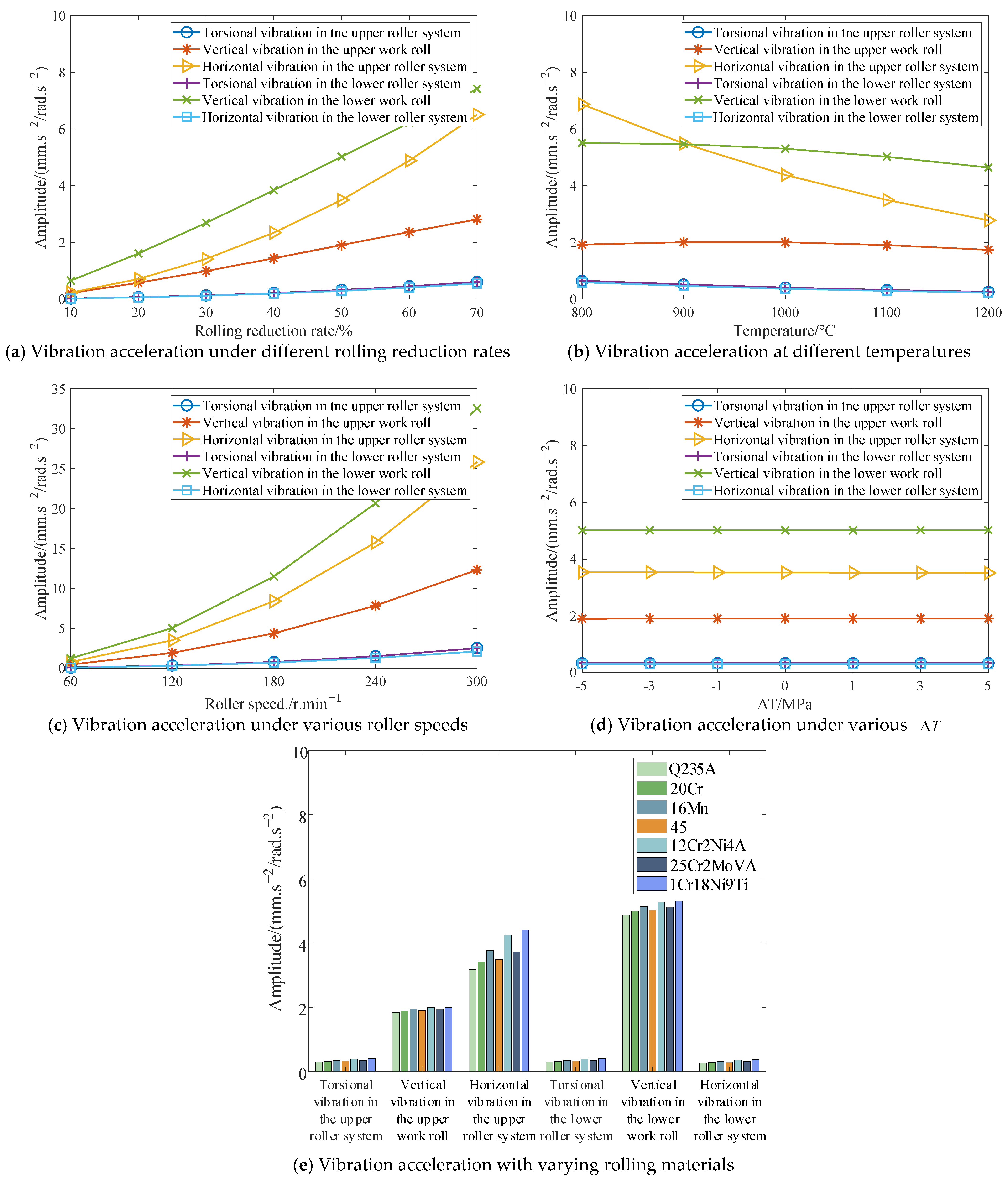
3.2. Research on the Influence of Rolling Process Parameters

The influence of typical rolling process parameters on the vibration of the rolling mill was examined using the control variable method, which meant only studying the varying parameters; other parameters remained unchanged. Excitations F 1 y , M T 1 , and F 1 X in Equation (4) were substituted with P , M Q , and F X , respectively, in the form depicted in Figure 10 for calculations. The vibration response of the upper roller system is illustrated in Figure 11. The associated parameters for calculation are tabulated in Table 4.
The amplitude of the steady-state vibration response from the rolling mill was obtained for different process parameters. These parameters included different rolling reductions, rolling piece materials, front and rear tension differences, temperatures, and rolling speeds. Figure 12 demonstrates the amplitudes of both torsional and horizontal vibrations in the upper and lower roller systems, along with the vertical vibration amplitudes recorded in the upper and lower work rolls.
Figure 12 demonstrates that the vibration amplitudes of both the upper and lower work rolls are equal in the torsional direction. Furthermore, when comparing the two in the vertical direction, the upper work roll exhibits a smaller vibration amplitude contrasted with the lower work roll. In contrast, the horizontal vibration amplitude of the lower roll system is less than that of the upper roll system.
From Figure 12a, one can see that the amplitude of vibration acceleration in the roll system progressively increases with the rolling reduction rate. This is because the excitations will be increased with the rolling reduction rate while the equivalent stiffness will be decreased with it, which amplifies the vibration of the whole rolling mill.
It can be seen from Figure 12b that as the temperature of the rolled piece increases, the overall vibration amplitude in the rolling mill system decreases. This phenomenon can be elucidated as follows. As the temperature of the rolling piece rises, the resistance to deformation experienced by rolling piece will decrease, which leads to a reduction in excitations P , M Q , and F X to some extent, but also decreases the stiffness of the rolled components in both vertical and horizontal directions. Under the comprehensive action, it leads to the emergence of such a phenomenon.
Furthermore, the rotation speed of the roller has a substantial effect on vibration, which is depicted in Figure 12c; as the rotation speed increases, the vibration of the rolling mill intensifies.
As illustrated in Figure 12d, variations in front and rear tension differences have little impact on vibration levels. Though the front and rear tension difference is positively related to the excitation in the horizontal direction, the hot mill is a kind of micro-tension rolling, hence the front and rear tension difference in the hot continuous mill is usually small, which will have little effect on the vibration of the mill.
As shown in Figure 12e, the influence of seven distinct typical materials used in the rolled piece on vibration indicates that the overall vibration amplitude increases with the hardness of the material, which is in accordance with common sense.
In summary, the rolling reduction rate and rolling speed are two most sensitive parameters to vibration of the whole rolling mill, and they are also very convenient to adjust during rolling production. These adjustments can be used to mitigate the vibration of rolling mills when abnormal vibration occurs. In addition, when processing harder material billets, overall vibration tends to increase, necessitating a reduction in the rolling reduction rate. Furthermore, the difference between the front and rear tensions has little impact on the vibration amplitude. As for the temperature of the rolled pieces, increasing it to some degree could be helpful to reduce the vibration of the whole rolling mill.

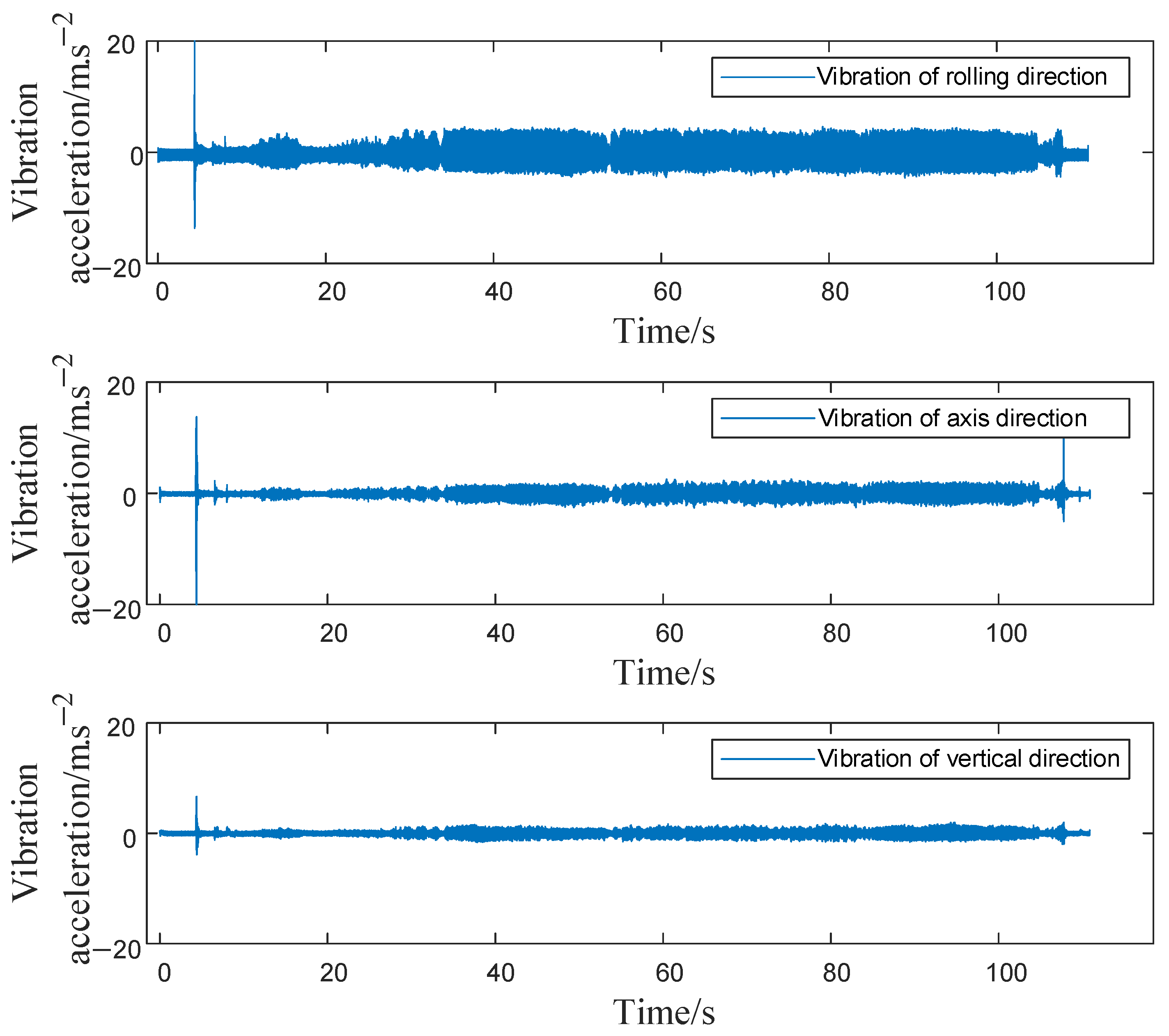
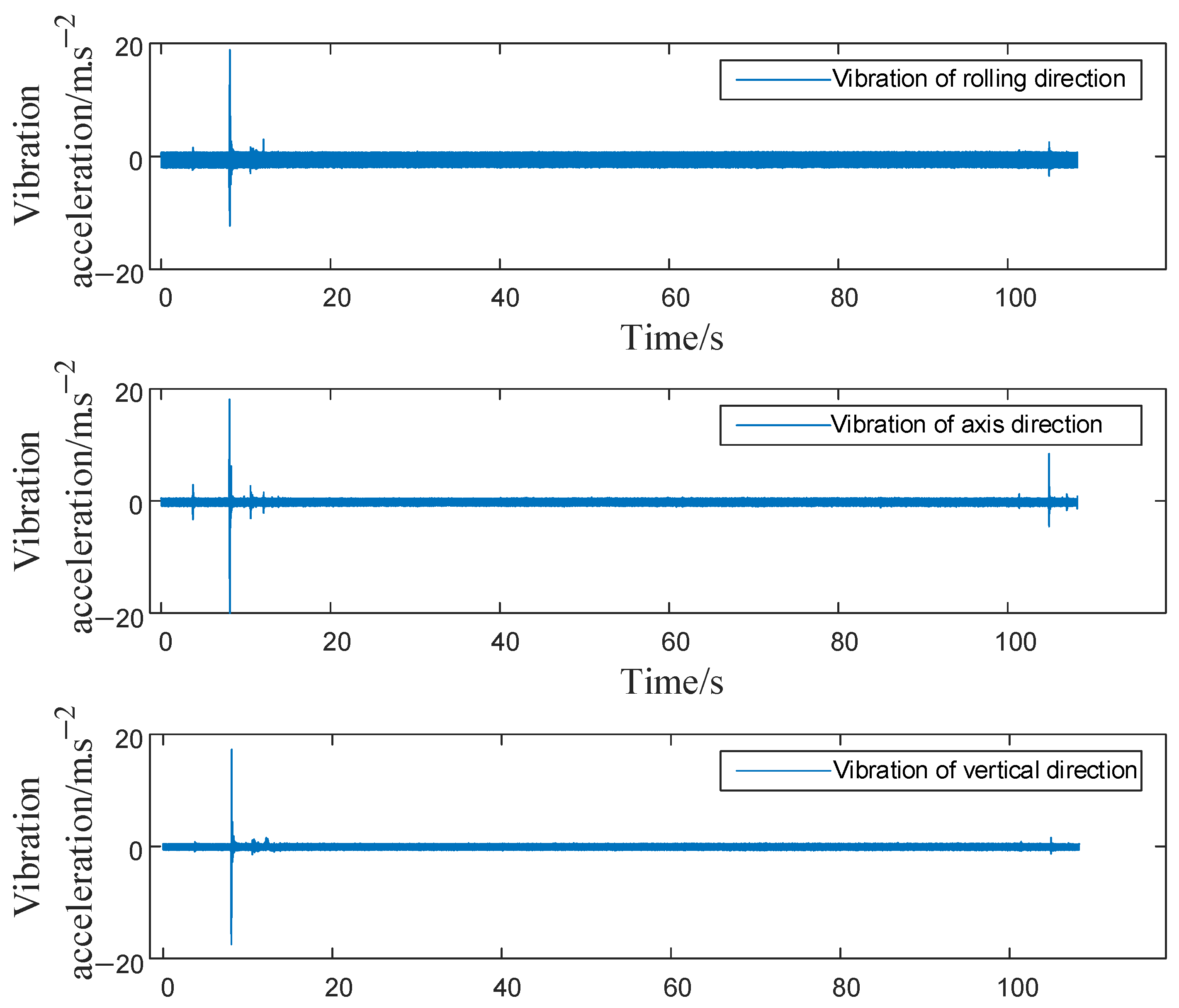
4. On-Site Vibration Reduction Application in Rolling Mills

In practical applications, the rolling reduction amounts achieved by the F1 and F2 rolling mills represent the largest proportion of the total reduction required due to the regulations governing the rolling process. Ensuring that the rolling reduction rate in the F2 rolling mill remains within an appropriate range is essential. Furthermore, the temperature of the rolled piece must be meticulously controlled within a specific range to achieve the desired crystal structure and performance standards during the rolling process. As hot rolling is characterized by micro-tension rolling, the difference in tension between the front and rear is small. Additionally, to ensure production efficiency, the adjustable range of roll speed is limited. Based on the aforementioned factors, the chosen method to reduce rolling reduction rate was applied to suppress the vibration amplitude of the F2 rolling mill in the hot continuous finishing mill.
The vibration signal obtained from the upper backup roller bearing seat located on the transmission side was shown in Figure 13, which was measured on-site when the F2 rolling mill processed B420CL rolling pieces with a product specification of 2 mm × 1253 mm under a rolling reduction rate of 60%. The layout of the measurement is the same as that shown in Figure 5. From Figure 13, it can be seen that even after the rolled piece enters the steady-state rolling stage, the rolling mill continues to experience significant vibrations until the rolled piece is ejected, with the vibration exhibiting a noticeable divergence. In addition, a large booming noise was heard on site.
To mitigate the vibration of the rolling mill, according to the above analysis, adjusting the reduction rate was adopted. Figure 14 illustrates the response at the same measuring point of the rolling mill after decreasing the rolling reduction rate to 48%. The measured vibration response indicates a significant decrease in vibration of the rolling mill, effectively addressing the issue of excessive on-site vibration. This result validates the correctness of the conclusions presented in this work.

5. Conclusions

This study develops a torsional-vertical-horizontal coupled dynamic model for the hot rolling mill, taking into account both the different vibration directions and the rolling parameters, and explores how the rolling parameters affect the vibrations in the F2 rolling mill. By analyzing the vibration signals from the upper back-up rollers and reduction boxes of the F2 rolling mill, as well as ensuring that the current signals during the rolling mill are working, the NF of the F2 rolling mill were determined. Additionally, ANSYS finite element software was employed to conduct simulation experiments, thereby verifying the correctness of the constructed dynamic model.
Employing the coupling model of the rolling mill system, this research examined how different typical parameters, including rolling reduction, temperature of the rolling piece, and rolling speed, influence the vibrations within the rolling mill system. The results indicate that a higher reduction rate and the increasing of roll speed leads to an amplification of the vibration amplitude in the rolling mill. Additionally, a rise in strip temperature contributes to a decrease in overall vibration of the rolling mill. Higher vibrations are observed when the hardness of the billet material is heightened. The difference in tension between the front and rear sections has a negligible effect on vibration levels.
In order to tackle the issue of excessive vibration occurring at the rolling mill, the on-site vibration was mitigated by adjusting the process parameters. Taking into account the influence of these parameters and their adjustable range, vibration reduction was achieved by decreasing the rolling reduction rate. Specifically, the rolling reduction rate of the F2 rolling mill was reduced from 60% to 48%. This modification significantly reduced the vibration amplitude of the rolling mill on site and confirmed the accuracy of the theoretical analysis.
The research could be helpful for rolling mill modelling, especially for digital twins of rolling mills that consider both the structure and rolling process. This work also provides guidance for controlling vibrations in rolling mill systems on-site with less efforts. However, the research does have certain limitations. For instance, it overlooks the interactions between the rolling mills within the rolling mill unit, and the model does not account for the asymmetry of the rolls during actual operation. In addition, the friction in the rolling interface is simplified without considering the slip, and all nonlinearities are neglected. These limitations will be considered in the future work to construct a more accurate model for the hot rolling mill.

Author Contributions

Conceptualization, Z.L. and H.X.; Funding acquisition, Z.L.; Investigation, Z.L., D.Z. and D.Y.; Methodology, D.Z. and H.X.; Supervision, H.X.; Validation, D.Z. and D.Y.; Writing—original draft, Z.L. and D.Z.; Writing—review and editing, Z.L. and H.X. All authors have read and agreed to the published version of the manuscript.

Funding

This research was funded by the National Natural Science Foundation of China (52375118). And The APC was funded by the National Natural Science Foundation of China (52375118).

Data Availability Statement

Data will be available once asked by the readers.

Conflicts of Interest

Author Danfeng Yu was employed by the company Wuhan Iron and Steel Co., Ltd. The remaining authors declare that the research was conducted in the absence of any commercial or financial relationships that could be construed as a potential conflict of interest.

References

  1. Zhang, G.; Bao, J.; Li, W.; Wang, Z.; Meng, X. Coupled vibration characteristics analysis of hot rolling mill with structural gap. Shock Vib. 2021, 2021, 5581398. [Google Scholar] [CrossRef]
  2. Hou, D.; Sun, Z.; Mu, J.; Shi, P. Vertical Vibration Characteristics of strip rolling mill under compound roll bearing failure. ISIJ Int. 2022, 62, 179–190. [Google Scholar] [CrossRef]
  3. Qi, J.-B.; Wang, X.-X.; Yan, X.-Q. Influence of mill modulus control gain on vibration in hot rolling mills. J. Iron Steel Res. Int. 2020, 27, 528–536. [Google Scholar] [CrossRef]
  4. Zhang, Y.; Lin, R.; Zhang, H.; Peng, Y. Vibration prediction and analysis of strip rolling mill based on XGBoost and Bayesian optimization. Complex Intell. Syst. 2023, 9, 133–145. [Google Scholar] [CrossRef]
  5. Jiang, L.; Wang, T.; Huang, Q.-X. Resonance Analysis of Horizontal Nonlinear Vibrations of Roll Systems for Cold Rolling Mills under Double-Frequency Excitations. Mathematics 2023, 11, 1626. [Google Scholar] [CrossRef]
  6. Kimura, Y.; Sodani, Y.; Nishiura, N.; Ikeuchi, N.; Mihara, Y. Analysis of chatter in tandem cold rolling mills. ISIJ Int. 2003, 43, 77–84. [Google Scholar] [CrossRef]
  7. Fan, X.; Zang, Y.; Jin, K. Rolling process and its influence analysis on hot continuous rolling mill vibration. Appl. Phys. A 2016, 122, 1–8. [Google Scholar] [CrossRef]
  8. Zeng, L.; Zang, Y.; Gao, Z. Multiple-Modal-Coupling Modeling and Stability Analysis of Cold Rolling Mill Vibration. Shock Vib. 2016, 2016, 2347386. [Google Scholar] [CrossRef]
  9. Peng, R.; Zhang, X.; Shi, P. Vertical–horizontal coupling vibration of hot rolling mill rolls under multi-piecewise nonlinear constraints. Metals 2021, 11, 170. [Google Scholar] [CrossRef]
  10. Liu, Y.; Wang, S.; Wang, X.; Yan, X. Research on Multi-System Coupling Vibration of a Hot Tandem Mill. Machines 2024, 12, 302. [Google Scholar] [CrossRef]
  11. Chen, X.; Li, J.; Ma, J. Dynamical responses for a vertical vibration model of a four-roller cold rolling mill under combined stochastic and harmonic excitations. Probabilistic Eng. Mech. 2023, 73, 103480. [Google Scholar] [CrossRef]
  12. Wu, J.; Yan, X. Coupling vibration model for hot rolling mills and its application. J. Vibroeng. 2019, 21, 1795–1809. [Google Scholar] [CrossRef]
  13. Qian, C.; Zhang, L.; Hua, C.; Bai, Z. Adaptive fuzzy vertical vibration suppression control of the mechanical-hydraulic coupling rolling mill system with input dead-zone and output constraints. IEEE Access 2020, 8, 85793–85801. [Google Scholar] [CrossRef]
  14. Yang, Y.; Peng, Y. Dynamic rolling model based on uniform deformation. J. Manuf. Process. 2020, 58, 1334–1347. [Google Scholar] [CrossRef]
  15. Wang, L.; Yan, X.; Jia, X.; Wang, X. Dynamic Amplitude-Frequency Characteristics of Vertical–Torsional Coupling System with Harmonic Response in Hot Tandem Mill. Electronics 2022, 11, 3031. [Google Scholar] [CrossRef]
  16. Xu, H.; Cui, L.-L.; Shang, D.-G. A study of nonlinear coupling dynamic characteristics of the cold rolling mill system under different rolling parameters. Adv. Mech. Eng. 2017, 9, 1687814017713706. [Google Scholar] [CrossRef]
  17. Jia, X.; Wang, S.; Yan, X.; Wang, L.; Wang, H. Research on dynamic response of cold rolling mill with dynamic stiffness compensation. Electronics 2023, 12, 599. [Google Scholar] [CrossRef]
  18. Sun, C.; Zhao, W.; Huang, D.; Zhang, H. Stability of nonlinear vibrations induced by rolling force in a precise cold mill system. Appl. Math. Model. 2023, 119, 196–217. [Google Scholar] [CrossRef]
  19. He, D.-P.; Xu, H.-D.; Wang, M.; Wang, T.; Ren, C.-R.; Wang, Z.-H. Application of dynamic vibration absorber for vertical vibration control of corrugated rolling mill. J. Iron Steel Res. Int. 2023, 30, 736–748. [Google Scholar] [CrossRef]
  20. Wang, M.; Xu, H.; He, D.; Wang, T.; Zhang, J. Design of a damped vibration absorber to control the resonant vibration of roll. Mech. Syst. Signal Process. 2022, 178, 109262. [Google Scholar] [CrossRef]
  21. Xu, H.; Wang, M.; He, D.; Wang, T. Vibration transmission and energy dissipation of roll controlled by particle damping absorber. Int. J. Mech. Sci. 2023, 249, 108264. [Google Scholar] [CrossRef]
  22. Zhang, H.; Zhao, W.; Huang, D.; Sun, C.; Fan, J. Vertical nonlinear vibration analysis of cold rolling mill considering structural gap and dynamic rolling force. J. Manuf. Process. 2023, 108, 280–291. [Google Scholar] [CrossRef]
  23. Lu, X.; Sun, J.; Wei, Z.; Li, G.; Zhang, D. Effect of minimum friction coefficient on vibration stability in cold rolling mill. Tribol. Int. 2021, 159, 106958. [Google Scholar] [CrossRef]
  24. Jia, X.; Yan, X.; Wang, L. Influence Factors of Inherent Characteristics of F5 Cold-Rolling Mill’s Main Drive System. Math. Probl. Eng. 2022, 2022, 2082210. [Google Scholar] [CrossRef]
  25. Lu, X.; Sun, J.; Li, G.; Wang, Q.; Zhang, D. Dynamic analysis of vibration stability in tandem cold rolling mill. J. Mech. Work. Technol. 2019, 272, 47–57. [Google Scholar] [CrossRef]
  26. Wright, J. Mill drive system to minimize torque amplification. Iron Steel Eng. 1976, 53, 56–60. [Google Scholar]
  27. Yuan, G.M.; Wang, J.; Xiao, H.; Li, M.L. Research on online model of vertical rolling force in hot strip roughing trains. Adv. Mater. Res. 2011, 145, 198–203. [Google Scholar] [CrossRef]
  28. Arnold, R.R.; Whitton, P.W. Spread and roll force in rod rolling. Met. Technol. 1975, 2, 143–149. [Google Scholar] [CrossRef]
  29. Sims, R.B. The Calculation of roll force and torque in hot rolling mills. Proc. Inst. Mech. Eng. 1954, 168, 191–200. [Google Scholar] [CrossRef]
Figure 1. Structure drawing of rolling mill.
Machines 12 00629 g001
Figure 2. Torsional-vertical-horizontal coupled dynamic model of the rolling mill system.
Machines 12 00629 g002
Figure 3. 3D finite element model of F2 rolling mill.
Machines 12 00629 g003
Figure 4. Mode shapes of finite element modal analysis.
Machines 12 00629 g004
Figure 5. Experimental arrangement on site.
Machines 12 00629 g005
Figure 6. Bite signal from upper back-up rolling vibration measurement point.
Machines 12 00629 g006
Figure 7. Signal of rolling current.
Machines 12 00629 g007
Figure 8. Impact signal from the vertical vibration measurement point the gearbox.
Machines 12 00629 g008
Figure 9. Geometric relationship between rolling force and rolling torque.
Machines 12 00629 g009
Figure 10. Excitation function of rolling mill during biting into billet.
Machines 12 00629 g010
Figure 11. Vibration of upper roller system.
Machines 12 00629 g011
Figure 12. Vibration acceleration under different rolling process parameters.
Machines 12 00629 g012
Figure 13. Measured signal of upper back-up roller bearing seat with 60% rolling reduction rate.
Machines 12 00629 g013
Figure 14. Measured signal of upper back-up roller bearing seat with 48% rolling reduction rate.
Machines 12 00629 g014
Table 1. Equivalent parameters of F2 rolling mill structure.
Moment of Inertia/(kg·m2)Effective Mass/(kg)Effective Stiffness/(N·m/rad)Effective Stiffness/(N·m−1)
J 1 = 8.93 × 10 4 m 1 = 2.32 × 10 5 k 1 = 1.093 × 10 9 K 1 = 9.45 × 10 10
J 2 = 2.19 × 10 4 m 2 = 7.6 × 10 4 k 2 = 1.32 × 10 9 K 2 = 5.5 × 10 10
J 3 = 6.87 × 10 3 m 3 = 3 × 10 4 k 3 = 7.4 × 10 8 K 3 = 5.28 × 10 10
J 4 = 2.26 × 10 3 m 4 = 3 × 10 4 k 4 = 1.274 × 10 8 K 4 = 4.5 × 10 11
J 5 = 3.65 × 10 2 m 5 = 7.5 × 10 4 k 5 = 1.274 × 10 8 K 5 = 5.28 × 10 10
J 6 = 3.65 × 10 2 m 6 = 6.5 × 10 4 k 6 = 1.37 × 10 8 K 6 = 7 × 10 10
J 7 = 5.14 × 10 3 M 1 = 1.81 × 10 5 k 7 = 1.37 × 10 8 K 7 = 2.4 × 10 11
J 8 = 5.14 × 10 3 M 2 = 1.8 × 10 5 K H 1 = 4.7 × 10 9
K H 2 = 5.9 × 10 10
Table 2. Theoretical calculation of F2 rolling mill NF.
NFValue (Hz)NFValue (Hz)
1st-order torsional mode15.81st-order vertical mode84.6
2nd-order torsional mode35.52nd-order vertical mode132.8
3rd-order torsional mode72.53rd-order vertical mode191.6
4th-order torsional mode1121st-order horizontal mode25.6
5th-order torsional mode146.72nd-order horizontal mode91.1
Table 3. The comparison of theory model and finite element model.
NFTheory Model (Hz)Finite Element Model (Hz)Error Rate (%)
1st-order torsional15.815.950.95
2nd-order torsional35.536.552.96
3rd-order torsional72.572.540.001
1st-order horizontal25.624.54.49
2nd-order horizontal91.186.55.05
1st-order vertical84.684.930.39
2nd-order vertical132.8
Table 4. Rolling relevant parameters.
ParameterValue
Base deformation resistance σ 0 (45 steel)162 MPa
Deformation resistance formula coefficients (45 steel)A = 3.539; V = −2.78; C = −0.157; J = 0.226; E = 1.37; N = 0.342
Work roll radius R 0.425 m
Billet temperature T t e m p 1100 °C
Reduction rate ε 50%
Friction circle radius R f 2 0.0322 m
Backup roll radius R 2 0.8 m
Force arm a R 0.0326 m
Rolling speed n 0 120 r/min
Rolled piece dimension6 mm × 1250 mm
Disclaimer/Publisher’s Note: The statements, opinions and data contained in all publications are solely those of the individual author(s) and contributor(s) and not of MDPI and/or the editor(s). MDPI and/or the editor(s) disclaim responsibility for any injury to people or property resulting from any ideas, methods, instructions or products referred to in the content.

