Article

Design and Testing of a Fully Automatic Aquatic Plant Combing Machine for Crab Farming

1
School of Mechanical Engineering, Yangzhou University, Yangzhou 225127, China
2
School of Mechanical Engineering, Jiangsu University, Zhenjiang 212000, China
*
Author to whom correspondence should be addressed.
Machines 2024, 12(9), 639; https://doi.org/10.3390/machines12090639
Submission received: 15 August 2024 / Revised: 7 September 2024 / Accepted: 9 September 2024 / Published: 12 September 2024
(This article belongs to the Section Machine Design and Theory)

Abstract

:
To meet the requirements of the crab growth environment regarding aquatic plant density and improve the efficiency of aquatic plant clearing, this paper shows the development process of a fully automatic aquatic plant combing machine for crab farming. It proposed the use of torsion spring hooks to replace traditional cutting blades to break tangled aquatic plants, reducing the length of aquatic plants in dense areas and thus controlling the density of aquatic plants in crab ponds. Through theoretical analysis and calculation of the torsion spring hooks, it was ensured that they could meet the design requirements, and transient dynamic simulation tests were conducted based on ANSYS. Finally, experimental verification was carried out. The performance test results of the torsion spring hooks showed that the torsion force generated within a certain torsion angle range could break the aquatic plant, and obstacles could be avoided through self-deformation. The water performance test results showed that the average clearing efficiency of the whole machine for aquatic plants was 4.92 mu/h, the missed clearing rate of aquatic plants was 0.44%, and the crab injury rate was 0.028%. The design of this machine can provide a reference for the development of aquatic plant harvesters for crab farming.

1. Introduction

As a typical product of freshwater aquaculture, river crab is deeply loved by foodies due to its delicate meat texture and high nutritional value. In recent years, the aquaculture scale has been expanding year by year, making it the largest single-product industry in freshwater fisheries in terms of output value [1,2,3]. As the saying goes, ‘the size of the crab depends on the aquatic plant’. The quality of aquatic plant maintenance in river crab ponds is directly related to the success or failure of river crab aquaculture throughout the year [4,5]. River crab aquaculture has certain requirements for the density of aquatic plants. If the density of aquatic plants is too low, river crabs may not find hiding places during molting, increasing their mortality rate. If the density is too high, it can easily create an oxygen-deficient environment in the pond, leading to root rot in the aquatic plants, bacterial growth, and crabs ‘climbing uphill’ due to oxygen deficiency. Therefore, it is necessary to screen out excessive and dense aquatic plant growth in time during the rapid growth period of aquatic plants [6,7,8]. Currently, due to a lack of effective small-scale harvesting equipment for aquatic plants in river crab pond aquaculture [9], most ponds still adopt manual harvesting methods [10], which are labor-intensive and inefficient. Mechanized aquatic plant harvesting is of great significance to river crab aquaculture [11]. In response to this, scholars and enterprises from China and abroad have developed a variety of aquatic plant harvesting equipment. For example, Aquamarine, a company based in the United States [12], primarily produces large-scale, high-powered, hydraulically controlled aquatic plant harvesters, which are suitable for aquatic plant removal in large water areas. Kaizu et al. [13] from Japan developed an unmanned aquatic plant harvesting boat that uses a special structure propeller to prevent aquatic plant entanglement and achieve long-term automatic navigation. RS-Planering, a Finnish company [14], designed and manufactured the amphibious aquatic plant harvesting boat RS5000, shown in Figure 1, which mainly collects floating plants and has a certain storage capacity. The German company Berky’s [14] aquatic plant harvesting boat TYPE6400, shown in Figure 2, can cut aquatic plants 1.5 m below the water surface and various weeds on the slopes of river banks, and the cutting blade angle is fully adjustable. Zhang et al. [15] developed the SCSGJ-2.6 aquatic plant harvester, which adopts a reciprocating blade, mesh conveyor belt, and paddle wheel drive, and can walk on land. Wang [16] developed a detachable small aquatic plant harvester, which can be installed on ordinary boats through a specially designed mounting frame. It adopts a unique transmission mechanism to maximize transmission efficiency while ensuring adjustable harvesting depth. Xu [12] developed an amphibious aquatic plant harvesting boat that integrates aquatic plant cutting, conveying, and bundling. It can effectively harvest submerged aquatic plants and conveniently achieve fast shore unloading. Chen [17] developed an automatic aquatic plant harvesting equipment for river crab aquaculture, which has functions such as aquatic plant cutting, water depth sensing, cutting speed adjustment, and detachability. It can improve the efficiency of aquatic plant clearing for farmers and reduce labor intensity. Qi [18] designed a kind of lawnmower boat system with self-navigation functionality for shrimp and crab breeding waters, which can realize efficient operation and safe turning of the lawnmower boat, and reduce the harvest omission rate. Although the above-mentioned research equipment has improved the efficiency of aquatic plant harvesting, most of them are suitable for large water areas, and they cannot fully utilize bunkers for automatic collection of aquatic plants, nor can they control the density of the cut aquatic plants well.
The cutter, a key component of aquatic plant harvesting equipment, currently mainly adopts two types: rotary and reciprocating [19]. The rotary cutter has a fast cutting speed, but when the aquatic plant is in rapid growth, intertwined stems and leaves can easily cause issues such as the aquatic plant wrapping around the blade. The reciprocating cutter has a simple structure but suffers from problems like repeated cutting and missed cutting. Additionally, it can only cut aquatic plants at a certain height, and is unable to adjust the density of aquatic plants.
This research presents a solution to the aforementioned challenges by proposing the development of a fully automatic aquatic plant combing machine for crab farming. Based on the requirements of the river crab’s growth environment for aquatic plant density, a method is introduced that utilizes the torsional force of torsion spring hooks to separate and harvest tangled aquatic plants in dense areas. In contrast, aquatic plants in less dense areas, due to their shorter lengths and lack of entanglement, will not be cleared by the torsion spring hooks as they pass through, thereby achieving the goal of controlling aquatic plant density in crab ponds. This innovative aquatic plant clearing approach results in the development of a device that can automatically adjust its water entry depth for aquatic plant removal. Additionally, the study explores methods for spreading aquatic plants, leading to the creation of a structurally simple mechanism capable of evenly distributing aquatic plants and enabling fully automated aquatic plant management. This equipment aims to address issues such as poor aquatic plant clearing quality and low automation levels in river crab aquaculture, which is of great significance in advancing the mechanization and automation of the entire process of river crab farming in China.

2. Materials and Methods

2.1. Overall Structure and Working Principles of Fully Automatic Aquatic Plant Combing Machine

2.1.1. Overall Structure

The fully automatic aquatic plant combing and clearing machine for river crab farming developed in this paper consists of two main parts: an aquatic plant combing and clearing device and a fully automatic aquatic plant paving mechanism. The aquatic plant combing and clearing device includes an aquatic plant combing mechanism and a water depth adjustment mechanism, while the fully automatic aquatic plant paving mechanism comprises a drawer-style silo, silo support, damping mechanism, guide rail, hull, transmission system, etc. The overall structure is shown in Figure 3. In the aquatic plant combing mechanism, multiple torsion spring hooks are installed on the same support rod. The compression spring parts of adjacent torsion spring hooks touch each other to restrict axial movement. The upper limit ring of the fixed part is inserted into the previous support rod, and the limit ring is located between the adjacent left and right compression springs, restricting the movement of the fixed part and thus limiting the radial rotation of the torsion spring hook. Aquatic plant matter cleared by the combing mechanism in the drawer-style silo will accumulate in one area of the silo. Once it reaches a certain height, it moves backward a certain distance. The damping mechanism ensures that the silo can expand as envisioned and avoid multiple silos moving together due to external factors.

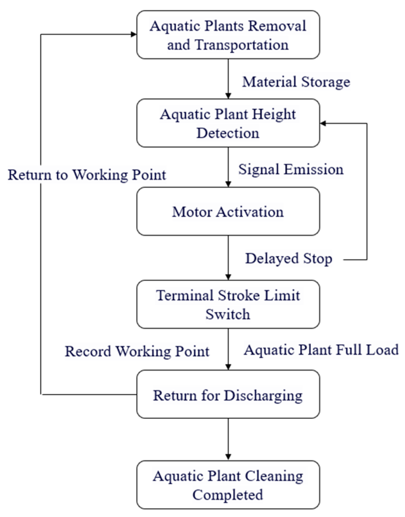
2.1.2. Working Principles

During the working process, the water depth adjustment mechanism drives the aquatic plant combing mechanism to automatically adjust the depth of water entry. The torsion spring hooks break off entangled aquatic plants in the water or directly salvage floating weeds on the water surface. Cleared aquatic plant matter, after being transported to the end by a chain drive, falls into the multi-section drawer-style silo due to its own weight. Once it reaches a certain height, the detection sensor sends a signal, and the motor starts, driving the topmost silo of the multi-section drawer-style silo to move a certain distance through chain transmission before stopping. The motor adopts delay control. Since the aquatic plant dropping position remains basically unchanged, the multi-section drawer-style silo only needs to move the fully loaded aquatic plant area. As the aquatic plant loading capacity continues to accumulate and increase, the multi-section drawer-style silo continuously moves until the silo’s terminal travel switch sends a signal indicating that the multi-section drawer-style silo is almost fully expanded. The aquatic plant area is fully loaded at 320 kg and returned to the shore for unloading. After unloading is complete, it returns to continue working until aquatic plant clearing in the crab pond is finished. The workflow is shown in Figure 4.

2.2. Design of Key Components and Parameters Determination

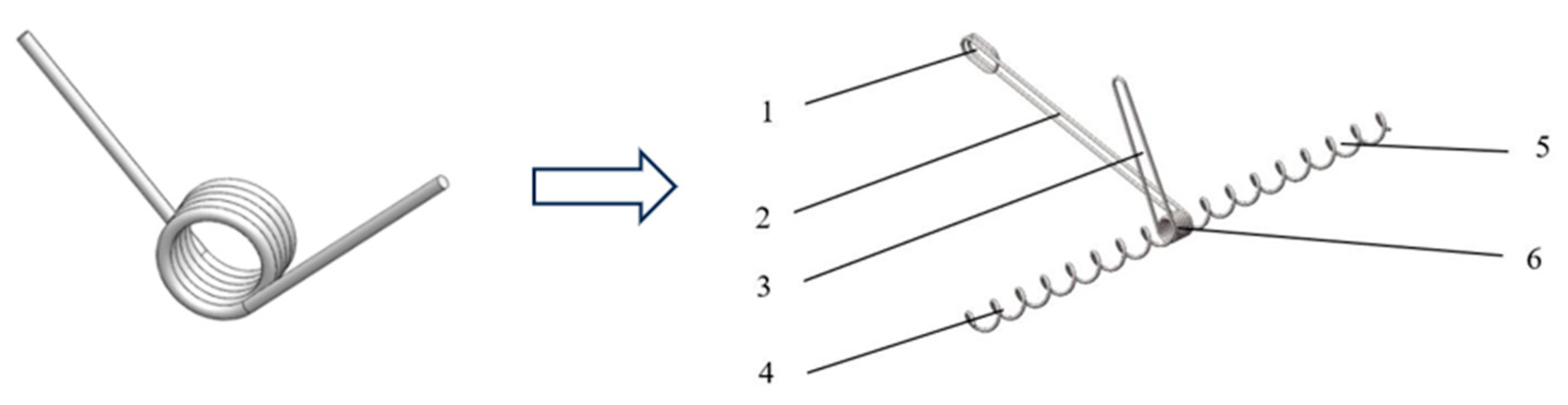
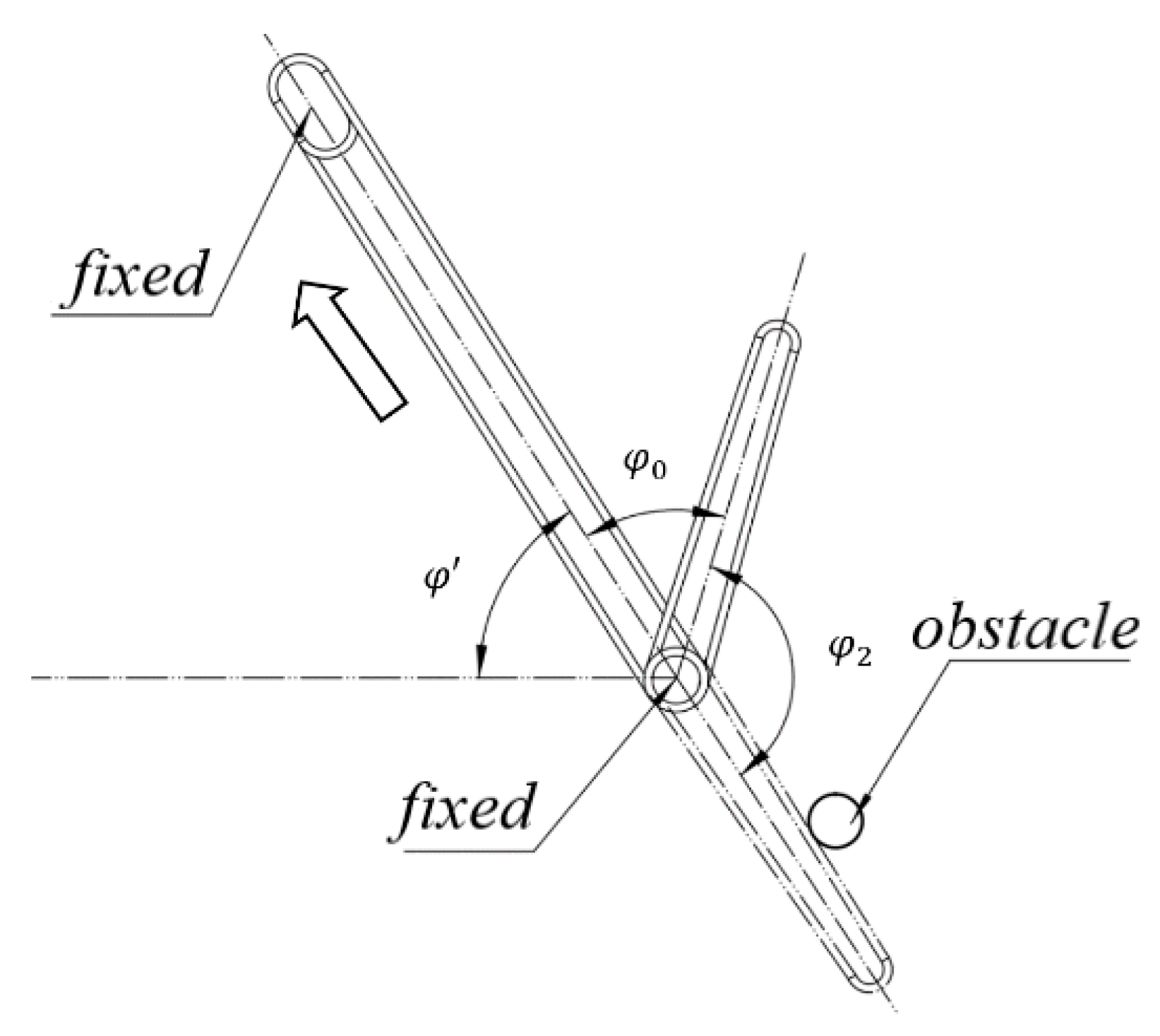
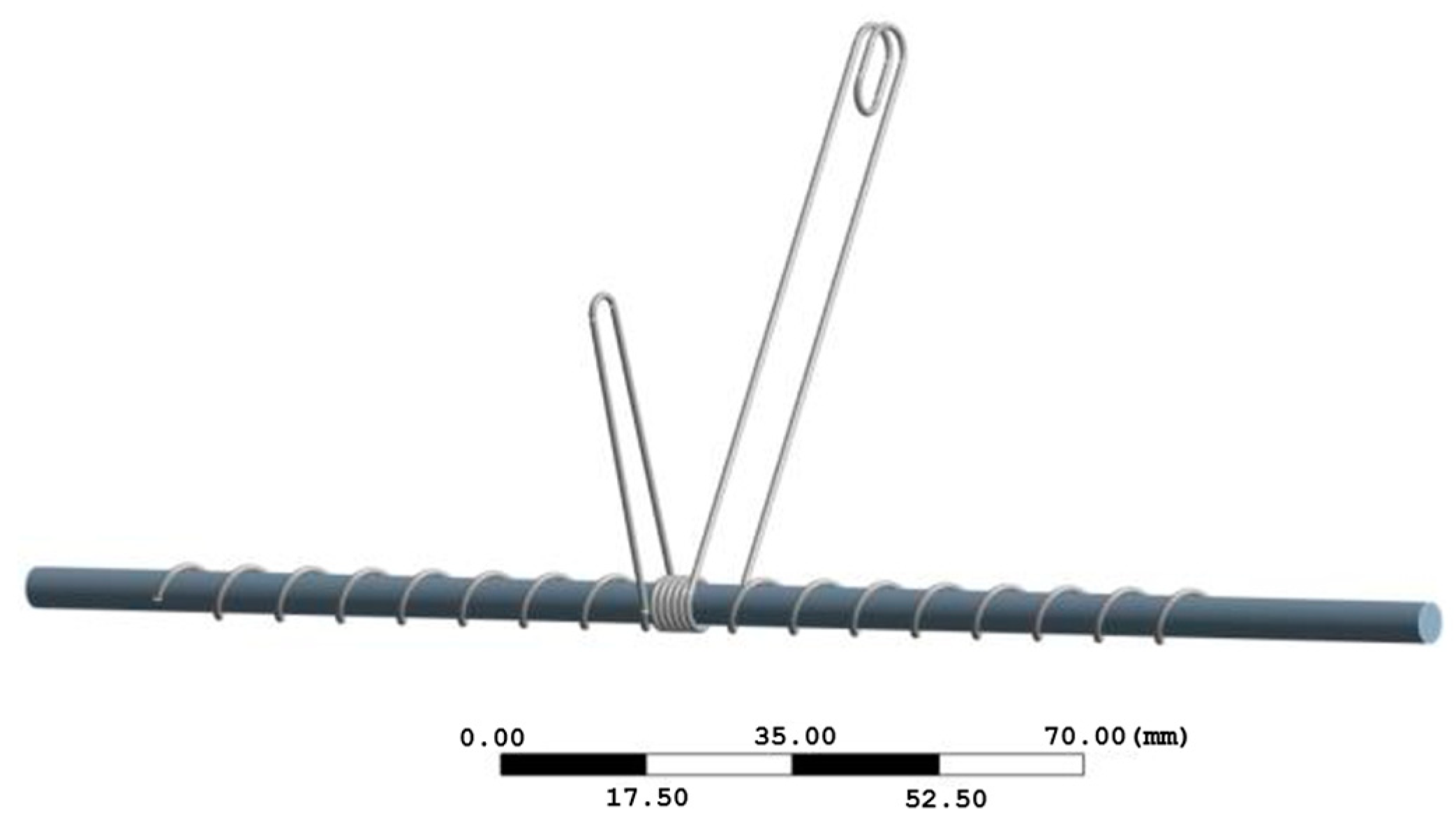
2.2.1. Design of Torsion Spring Hooks

A torsion spring hook is a non-standard component designed based on the requirements of aquatic plant clearing and installation convenience, referencing the design of a cylindrical torsion spring, as shown in Figure 5. Cylindrical torsion springs mainly bear torsional loads and are used for compression, energy storage, and as elastic components in transmission systems [20]. Considering that the torsion spring hooks are in long-term contact with water during operation, SUS304 stainless steel is used as the material.
As shown in Figure 6, multiple torsion spring hooks are installed on the same support rod. The inner diameter of the limit ring should be slightly smaller than the outer diameter of the pressure spring, so as to ensure that the limit ring of the previous torsion spring hook does not overlap with the pressure springs on both sides, and avoid the problems of disordered spacing between adjacent support rods and adjacent hooks.
Based on the conditions of aquatic plant clearing, the design of torsion spring hooks should meet the following requirements: (1) When the movable end of the torsion spring hook encounters an entangled aquatic plant, it should be able to generate sufficient torsion force to break the aquatic plant with a small torsion angle, preventing the broken aquatic plant from detaching from the torsion spring hook due to the rebound state of the torsion spring after breaking. (2) Since obstacles such as cables, ropes, and aeration pipelines often exist in crab farming ponds, it is necessary to avoid them through deformation of the torsion spring hooks themselves.
To meet requirement (1), as measured through experiments, when the torsion angle φ generated by the torsion spring hook is less than or equal to 20°, the rebound force generated by the torsion spring is not large and is directed towards the fixed end of the torsion spring hook. The operating characteristics of the torsion spring hook are similar to those of common springs. When the external torque does not exceed the allowable stress of the spring, the torque T and the torsion angle φ are linearly related. Therefore, the operating characteristic curve of the torsion spring hook is a straight line, as shown in Figure 7.
The main aquatic plants used in crab farming in China are Elodea, bitter grass, and Hydrilla verticillata, all of which are submerged aquatic plants [21]. Through mathematical statistical methods and water plant breaking force tests, it was measured that the maximum diameter of Elodea is 1.86 mm, with a corresponding breaking force of 2.45 N; the maximum diameter of Hydrilla verticillata is 2.66 mm, with a corresponding breaking force of 5.05 N; and the maximum cross-sectional width of bitter grass is 6.48 mm, with a corresponding breaking force of 5.47 N. Combined with the size of the torsion spring hook itself, it is assumed that the torsion spring hook can simultaneously break three aquatic plants at one time. Considering the practicality of the installation space, the torsion arm L is tentatively set to 38 mm, that is, the maximum breaking force F = 5.47 × 3 = 16.41 N. Therefore, applying a force F to the movable part of the torsion spring hook, we can obtain the torque at this time as:
T = F R
In the formula: R is the length of the force arm at the breaking position.
During the process of clearing aquatic plants with torsion spring hooks, the breaking point is located at the junction of the movable part and the torsion spring part of the torsion spring hook, which indicates that the breaking position arm is half of the radius or cross-sectional width of the aquatic plant. Among the three types of aquatic plant, bitter grass has the largest cross-sectional area at 6.48 mm, so the maximum arm R is taken as 3.24 mm. Substituting the maximum breaking force of aquatic plant F = 16.41 N, we can obtain T 1 = 53.17 N·mm. Then, the torsion angle φ 1 at this time is:
φ 1 = T 1 T
In the Formula: T is the torsional stiffness of the spring.
With φ 1 ≤ 20°, it can be obtained that when the spring torsional stiffness T ≥ 2.65 N·mm/(°), requirement (1) can be met.
Meeting requirement (2) places a demand on the stiffness of the torsion spring hook. Taking a cable as research object, by searching relevant literature [22], it can be found that the cross-sectional area is 50 mm; that is, the diameter is about 4 mm for insulated cable, the fixation method at both ends is the fitting crimping method, and the tensile rate is 100 mm/min. The average measured cable breaking force is 9.89 KN. Substituting this into Formula (1), we can obtain T = 19,780 N·mm at this time, and the stiffness T of the torsion spring hook is:
T = T K φ
In the Formula: K is the safety factor; φ is the torsion angle.
Looking up the mechanical design manual [23], we can obtain K = 3. To find the minimum value of the torsion spring hook, the torsion angle φ ≥ 180°. Substituting this into the formula, we can obtain T ≤ 36.63 N∙mm/(°).
As shown in Figure 8, the torsion angle generated by the torsion spring hook plays a decisive role in whether the obstacle can slide down. At this point, it is necessary to determine the torsion angle φ 2 at the critical state where the obstacle can overcome friction and slide freely. To simplify the calculation process, the torsion spring hook is set to move in a straight line at a uniform speed in the direction of the arrow.
To find the maximum torsion angle φ 2 , a force analysis is performed on the obstacle. The angle θ between the direction of gravity of the obstacle and the Y-axis is:
θ = φ + φ 0 + φ 2 π
The component force in the Y direction is:
F N = F G Y F 2 = G o b s t a c l e cos θ F 2 = m g cos θ F 2
F 2 = T 2 x = φ 2 T x
The component force in the X direction is:
f = μ F N = μ m g cos θ μ F 2
F G X = G o b s t a c l e sin θ = m g sin θ
Based on life experience, we can know that:
0 < x < L
In the formula: m represents the mass of the obstacle, F N is the supporting force in the vertical direction on an inclined plane, F G X is the component force of the obstacle’s gravity along the X-axis, F G Y is the component force of the obstacle’s gravity along the Y-axis, f is the friction force of the obstacle, μ   is the friction coefficient, T is the torsional stiffness of the torsion spring hook, and L is the length of the movable end of the torsion spring hook.
Looking up the mechanical design manual [23], it can be found that the friction coefficient μ of SUS304 stainless steel under sliding friction without lubrication is 0.3 to 0.4, and μ = 0.35 is taken. According to the above formula, it can be arranged along the X direction to obtain:
f < F G X μ m g cos θ μ φ 2 T x < m g sin θ θ = φ + φ 0 + φ 2 π
Combining requirements (1) and (2), the torsion spring component needs to satisfy:
μ m g cos θ μ φ 2 T x < m g sin θ θ = φ + φ 0 + φ 2 π 0 < x < L 2.65   T   36.63
In some extreme cases, to ensure that the torsion spring hook can still avoid obstacles without exceeding the allowable stress, it is necessary to ensure that the torsion spring hook can bend to 180°. In this way, as the torsion spring hook continues to move with the chain drive, it can still make the obstacle detach from the torsion spring hook, as shown in Figure 9. It can be obtained that:
φ 0 + φ 2 π
Under this condition, combined with requirement (1), the torsion spring hook needs to satisfy the following conditions:
φ 0 + φ 2 π 2.65   T   36.63
In summary, if the basic parameters of the torsion spring component satisfy Formulas (11) or (13), then the design requirements can be met.

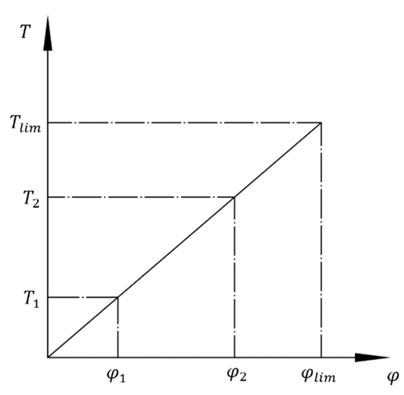
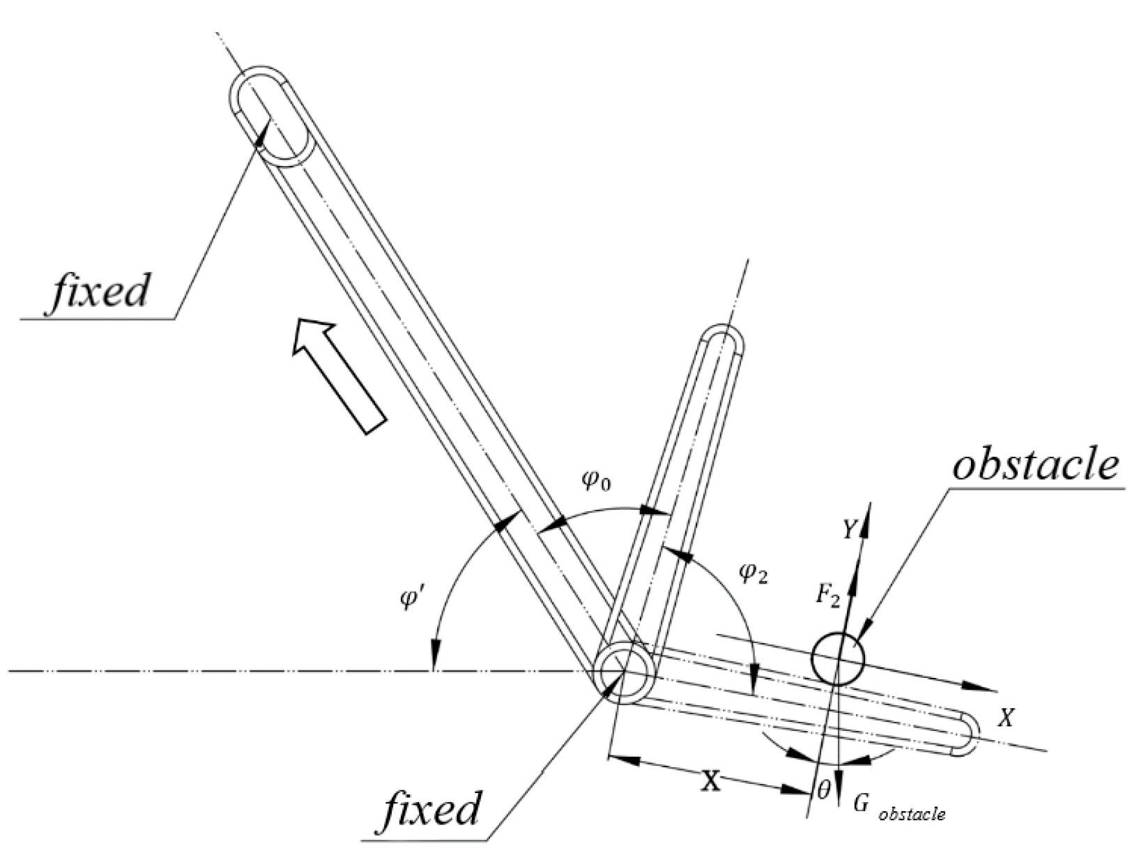
2.2.2. Theoretical Analysis and Calculation

The main working part of the torsion spring hook is basically similar to a cylindrical torsion spring, so its design and calculation can be referenced accordingly. The main parameters are shown in Figure 10. Taking into account the two requirements for using the torsion spring hook and the installation space, the initial free angle of the torsion spring hook is set at φ 0 = 45°, L = 30 mm, minimum torque T 1 = 56.12 N∙mm, maximum working torque T 2 = 170 N∙mm, and working torsion angle φ = 37°.
As mentioned above, the torsion spring hook is made of SUS304 stainless steel. Referencing the Mechanical Design Handbook [23], the physical properties of SUS304 stainless steel are listed in Table 1.
Based on the preliminary assumption of a diameter range of d = 0.8 to 1.3 mm, according to the GB/T 1239.6-2009 technical conditions for cold-coiled cylindrical helical springs part 2: compression springs, the tensile strength limit is found to be σ b = 1471 to 1863 Mpa [23]. Taking σ b = 1800 MPa, the tensile strength limit at this point is σ b = 2157 MPa. As shown in Table 2, the allowable stress values for torsion spring materials are:
σ B P = 0.75 σ b
Substituting the data, we can obtain σ B P = 1350 MPa.
To achieve a compact design, the initial winding ratio C is set to 5. The curvature coefficient K 1 can then be determined.
K 1 = 4 C 1 4 C 4
Substitute the data to obtain K 1 = 1.19, and referring to the Mechanical Design Handbook [23], the diameter d of the torsion spring hook is:
d = 32 T 2 K 1 π σ B P 3
By substituting the data, we obtain d = 1.15 mm. According to the preferred number series for the diameter of cylindrical torsion springs, we take the standard value of d = 1.2 mm. At this point, the tensile strength limit σ b is 2157 MPa, which is not lower than the original assumed value, thus it is safe. Therefore, the spring’s pitch diameter D is:
D = C d
By substituting the data, we can obtain D = 6 mm, and at this time, the number of spring coils n is:
n = E d 4 φ 3667 D ( T 2 T 1 )
In the formula, E represents the elastic modulus of SUS304 stainless steel.
By referring to Table 1, we know that E = 193 GPa. Substituting this, we obtain n = 5.91. According to standardization, we round it up to n = 6. The spring stiffness T is:
T = E d 4 3667 D n
Substituting the data, we obtain T = 3.03 N∙mm/(°). The torsion angles φ 2 at the maximum working torque and φ 1 at the minimum working torque of the torsion spring hook are:
φ 2 = T 2 T
φ 1 = φ 2 φ
Substituting data, we can obtain φ 2 = 56.11°, φ 1 = 18.89°, and the actual minimum working torque T 1 :
T 1 = T φ 1
Substituting the data, we obtain: T 1 = 57.23 N∙mm. The working limit torsion angle φ j of the torsion spring and the spring pitch t are:
φ j = π d 3 σ b 20 K 1 T
t = d + δ
In the formula, δ represents the torsion spring pitch, which is generally set to 0.5 outside special circumstances.
Substituting the data, we obtain: φ j = 135.4°, t = 1.7 mm. By referring to the Mechanical Design Handbook [23], the free length H 0 and helix angle a of the torsion spring hook are:
H 0 = n t + d
α = arctan t π D
Substituting the data, we obtain: H 0 = 11.4 mm, a = 5.14°. Substituting the above data into Formula (13) verifies its validity, indicating that the designed torsion spring meets the usage requirements.

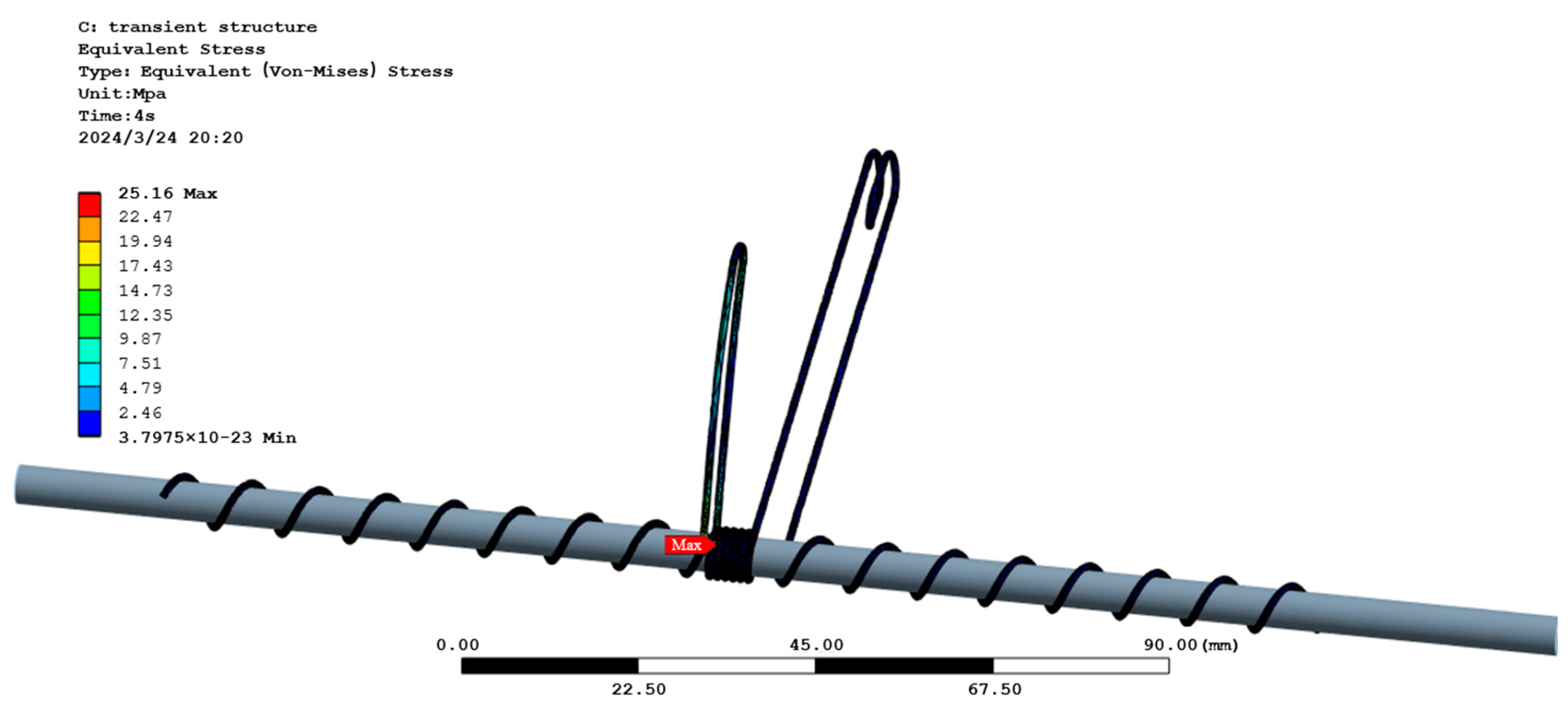
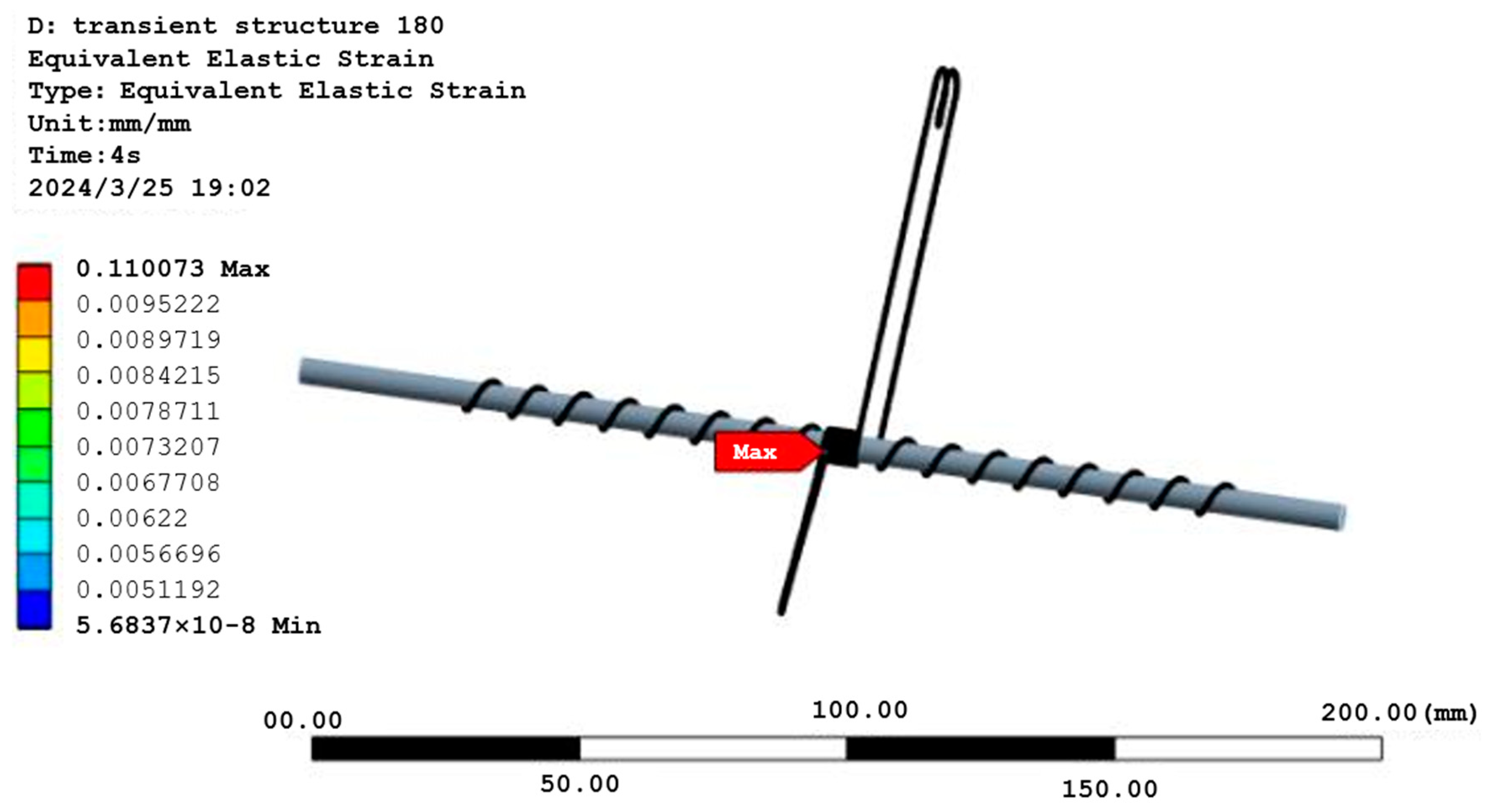
2.3. Transient Dynamics Simulation

Based on the structural design of the torsion spring hook completed according to the required specifications in the previous text, and the basic parameters obtained for the torsion spring hook, this paper explores whether the torsion spring hook can meet the usage requirements under two working conditions through transient dynamics simulation: ① We apply the breaking force F of the aquatic plant to the torsion spring hook, and check if the torsion angle is less than the set value. ② Due to the complexity of obstacles encountered by the torsion spring hook and the large number of unknown parameters, we now consider an extreme situation where the torsion spring hook is bent to 180°. We analyze its transient characteristics to obtain the maximum stress value and determine if it is less than the yield strength of SUS304 stainless steel.
Transient dynamics is essentially a time-history analysis primarily used to analyze the dynamic response of mechanical structures under dynamic external loads [24,25]. This paper mainly studies mechanical changes in the torsion spring hook during operation, while the other components only serve the purposes of installation, fixation, and load transfer. Therefore, the torsion spring hook is set as a flexible body element, and the support rod is set as a rigid body, which does not participate in dynamic calculations [26]. This simplified model is shown in Figure 11.
We assign SUS304 stainless steel as the material for the torsion spring hook. Mesh division of the torsion spring hook is carried out by the sweeping method. Src/Trg manually selects a source and target, which correspond to the initial circular section and the terminal circular section of the torsion spring hook, respectively. The mesh element size is 0.2 mm. After the virtual model is meshed, the number of elements is 492,309 and the number of nodes is 788,190. The mesh provides various functions to detect its quality, including four evaluation indicators: element quality, orthogonal quality, aspect ratio, and skewness. This paper selects element quality to evaluate the quality of the mesh. The evaluation criterion for element quality is that the closer the average value of the element quality of the mesh division is to 1, the better the quality; the closer it is to 0, the worse the quality of the mesh. As shown in Figure 12, the average value is 0.82074. According to the evaluation criteria, the quality of the mesh is good and can fully meet the simulation requirements.
As mentioned in Section 2.2.1, the torsion spring hook needs to meet two operating conditions: ① Apply the maximum breaking force of the aquatic plant to the moving end of the torsion spring hook, ensuring that the torsion angle is less than 20°. Use the split command to separate the part of the torsion spring hook where force needs to be applied, and input 16.41 N for the X-component. ② To allow the torsion spring hook to avoid obstacles in the crab pond, it needs to be able to bend to 180°. As stated in Section 2.2.2, the initial angle of the torsion spring hook is 45°. Therefore, apply a remote rotational force to the moving end of the torsion spring hook so that it can rotate to 135° within 4 s.

2.4. Performance Testing of Torsion Spring Hooks

To test whether the torsion force corresponding to a torsion angle of 20° for the torsion spring hook can exceed the maximum breaking force of aquatic plants, we conducted the following experiment. As shown in Figure 13, we used an industrial-grade universal angle meter and a push–pull force measuring instrument for the test. The measuring probe was replaced with a specialized one for measuring compressive forces. Since the initial free angle of the torsion spring hook is 45°, to achieve a torsion angle of 20°, the other end should be adjusted to the 65° position. Holding the push–pull force measuring instrument, we pressed down in the tangential direction until the moving end of the torsion spring hook aligned with the 65° measuring end of the universal angle meter. This alignment indicated that the torsion angle of the torsion spring hook was 20°. At this point, we noted the reading on the push–pull force measuring instrument and compared it to the maximum breaking force of an aquatic plant. This experimental setup allowed us to accurately measure the torsion force required to achieve a 20° torsion angle and determine whether it exceeds the maximum breaking force of an aquatic plant.
In addition, we tested whether the torsion spring hook can avoid obstacles such as cables, ropes, and aeration pipes through its own deformation. Under the condition that the torsion spring hook does not exceed its ultimate yield stress, the angle between the fixed end and the movable end of the torsion angle should be no less than 180°. Since the initial free angle of the torsion spring hook is 45°, it can be inferred that the torsion angle should be no less than 135°. We used a universal angle meter to measure, and each time made the torsion spring hook rotate at an angle of 135°. After repeated experiments, we measured whether there was any change in the initial free angle of the torsion spring structure.

2.5. Comprehensive Performance Test in Water

To verify whether the prototype’s various performances, such as aquatic plant harvesting rate, missed harvesting rate, and crab injury rate, meet the design requirements, the prototype was processed and assembled according to the structural design scheme for the fully automatic aquatic plant combing and clearing machine for crab farming. In its non-working state, the fully automatic aquatic plant combing and clearing machine has a length of 5.13 m, a width of 1.78 m, and a height of 1.16 m. In the working state, because the aquatic plant combing and clearing machine can automatically adjust to the depth of water entry, the overall length and height changes. Actual measurements show that the length ranges from 5.13 m to 4.79 m, the height ranges from 1.78 m to 1.97 m, and the width remains unchanged at 1.78 m. The experimental prototype after processing and assembly is shown in Figure 14 below.
The experimental site was in Gaoyou City, Jiangsu Province, China, where the water quality, PH value, dissolved oxygen content, and mineralization value of the aquaculture waters are all within the range suitable for the normal growth of crabs. Three different ponds were selected for the experiment to test the aquatic plant clearing efficiency, missed grass cutting rate, and crab injury rate of the prototype in different environments. This allowed us to analyze the stability and reliability of the fully automatic aquatic plant combing and clearing machine. The main measurement contents include the following three aspects:
(1)
Basic tests of the prototype
During normal operation of the fully automatic aquatic plant combing and clearing machine, various measurements and observations are made. These include checking for abnormal vibrations and noise from the aquatic plant combing motor, the depth adjustment motor for the aquatic plant combing mechanism, the aquatic plant even spreading motor, and the paddle wheel motor during a 30-min run at rated speed. Additionally, it involves assessing whether there is any loosening of connecting fasteners, the stability and leveling of the boat’s movement in the water, the normality of the depth adjustment process of the aquatic plant combing and clearing machine, the operating speed of the machine under full and empty loads, and the normal sustainable working time with a fully charged battery.
(2)
Aquatic plant harvesting efficiency
To measure aquatic plant harvesting efficiency, specific areas with similar aquatic plant density were selected in three ponds. The fully automatic aquatic plant combing and clearing machine was placed in these areas to start operation, and the area and operation duration were recorded to calculate the harvesting efficiency. The formula for calculating harvesting efficiency is as follows:
E = A T
E —clearing efficiency. A —clearing area. T —clearing time.
(3)
Missed clearing rate of aquatic plants and injury rate of river crabs
In the three experimental areas where the aquatic plant clearing work has been completed, one mu (a unit of area in China, equivalent to about 667 square meters) of land was randomly selected from each area for experimentation. Using a combination of image acquisition technology and manual calculation, the number of aquatic plant stems and the number of uncleared aquatic plant stems in each experimental plot were measured separately. The formula for calculating the missed clearing rate of aquatic plants is as follows:
M = U N
M —missed clearing rate of aquatic plants. U —number of uncleared aquatic plant stems. N —total number of aquatic plant stems.
In the experiment to determine the injury rate of river crabs, study was conducted in the three previously selected experimental areas, each covering an area of one mu. Crab traps were used to capture the crabs, and these traps were evenly distributed across the experimental areas. Once the traps were almost full, the crabs were collected, and the number of injured crabs was inspected and recorded. The formula for calculating the injury rate of river crabs is:
R = I A × P
R —injury rate of river crabs. I —number of injured river crabs. A —cleared area. P —the number of river crabs released per unit area.

3. Results and Discussions

3.1. Analysis of Transient Dynamics Simulation

A Stress nephogram of the torsion spring hook under the maximum breaking force F of aquatic plant is shown in Figure 15. As can be seen from the figure, the maximum stress reaches 25.16 MPa, which is far less than the yield strength of SUS304 stainless steel. Therefore, the torsion spring hook is safe under this operating condition. By inserting a flexible rotation angle probe during the solution process, the torsion angle is found to be 18.23°. After calculation and verification using Formula (20), the error between the simulated torsion angle and the calculated torsion angle is within 3.5%, which to some extent indicates the accuracy of this simulation.
A strain nephogram and stress nephogram of the torsion spring hook rotated to 135° are shown in Figure 16 and Figure 17, respectively. As can be seen from the figures, the maximum strain is 0.11 mm and the minimum strain is 5.68 × 10⁻⁸ mm, while the maximum stress reaches 119.8 MPa. However, this value is still less than the yield strength of SUS304 stainless steel, indicating that the torsion spring hook is safe under this operating condition. The location of the maximum stress point is basically the same as the location of the maximum stress point when the torsion spring hook is subjected to the breaking force of an aquatic plant, suggesting that a torsion spring hook rotated to 135° is within its normal operating range. After verification using the calculation formula for the torsion spring hook described in Section 2.2.2, the error between the calculated stress value and the simulated stress result is within 4%, which to some extent demonstrates the accuracy of this simulation.

3.2. Performance Testing Results of Torsion Spring Hooks

The experimental results are shown in Table 3. The torsion forces are all greater than the maximum breaking force of an aquatic plant. The average difference compared to the maximum breaking force of an aquatic plant is 2.556 N, indicating that the torsion spring hook can meet the design requirement of being able to break an aquatic plant when the torsion angle is less than 20°.
In addition, the experimental results on whether the torsion spring hook can avoid obstacles are shown in Table 4. In the first 50 repeated experiments, there was no change in the initial free angle of the torsion spring hook. By the 60th and 70th experiments, the initial free angle changed after testing, with a difference of 0.02° from the initial value. By the 80th and 90th experiments, the initial free angle differed by 0.04° from the initial value. After 100 experiments, the initial free angle differed by 0.08° from the initial value, with a variation of 0.18%. This meets the requirements for use, indicating that the torsion spring hook can avoid obstacles through its own deformation.

3.3. Comprehensive Performance Test Results in Water

(1)
Basic tests of the prototype
The measurement results are shown in Table 5. The fully automatic aquatic plant combing and clearing machine demonstrates good operational stability and stability when adjusting the depth of water entry. The no-load speed is 1.32 m/s, and the full-load speed is 1.05 m/s. The continuous working time when the battery is fully charged is 7.6 h, which meets the requirements for use.
(2)
Aquatic plant harvesting efficiency
The experimental results are shown in Table 6, indicating that the average clearing efficiency of the fully automatic aquatic plant combing and clearing machine is 4.92 mu/h.
(3)
Missed clearing rate of aquatic plant and injury rate of river crabs
The experimental results are shown in Table 7. Based on a calculation assuming 1200 crabs per mu are released, the average missed clearing rate of aquatic plants is 0.44%, and the injury rate of crabs is 0.028%. Both of these rates meet the design requirements.
This chapter conducts a transient dynamic simulation study on the torsion spring hook component using ANSYS, analyzing its deformation and stress distribution under two working conditions. By comparing the theoretical calculation values with the simulation values, it further demonstrates that the simulation results have a certain degree of accuracy. Basic performance tests and comprehensive performance tests in water were conducted on the prototype. The basic performance tests verified that the torsion spring hook component can meet the design requirements; the comprehensive performance tests in water verified that the prototype runs smoothly and adjusts the depth of water entry with good stability. Compared with a reciprocating aquatic plant harvesting boat with a cutter [17], the average aquatic plant clearing efficiency is increased by 0.9 mu/h, the aquatic plant missed clearing rate is reduced by 1.21%, and the crab injury rate is reduced by 0.072%, resulting in considerable economic benefits. Therefore, the fully automatic aquatic plant clearing machine developed in this paper significantly improves clearing efficiency, reduces labor intensity for farmers, and has high reliability and practicality.

4. Conclusions

(1)
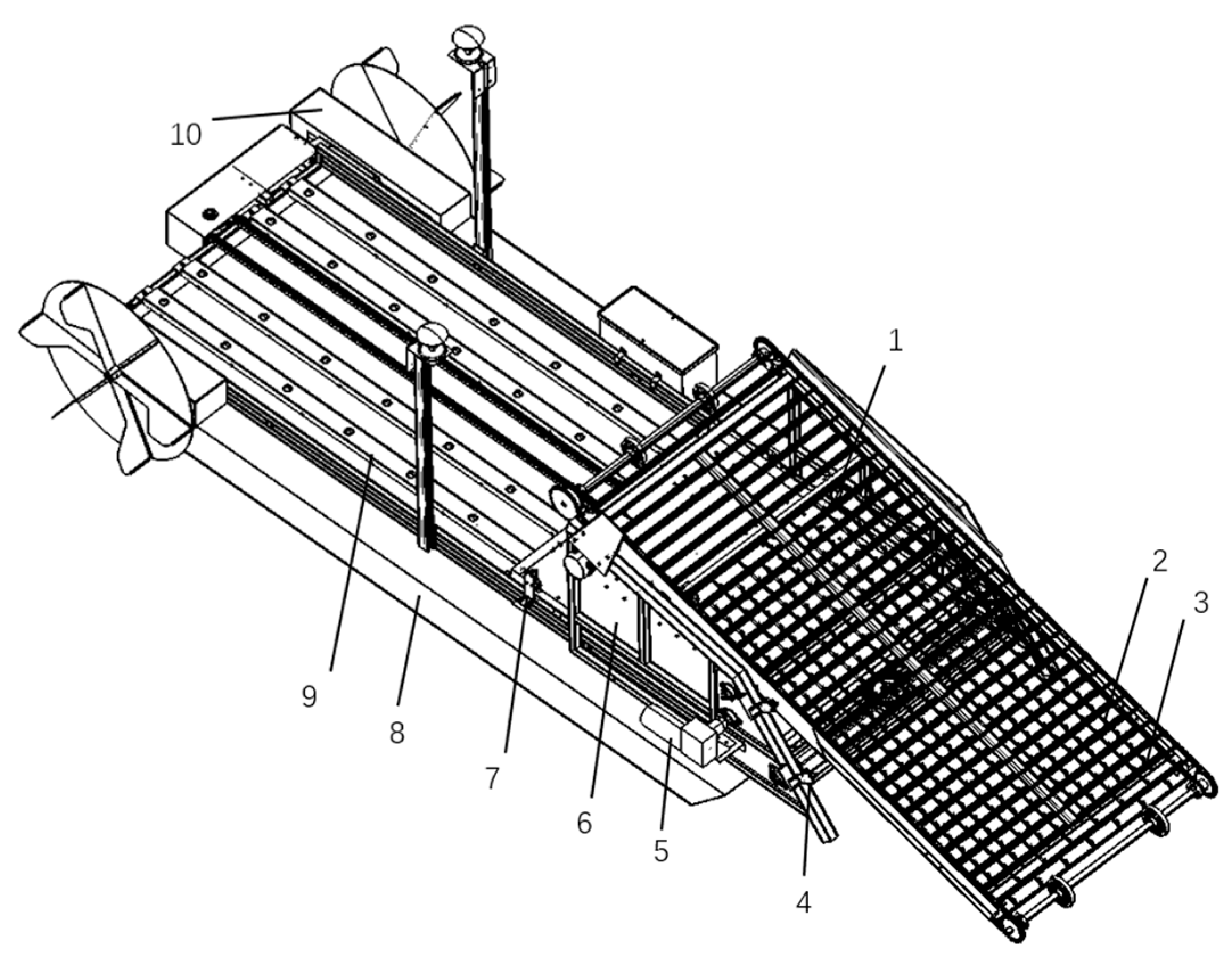
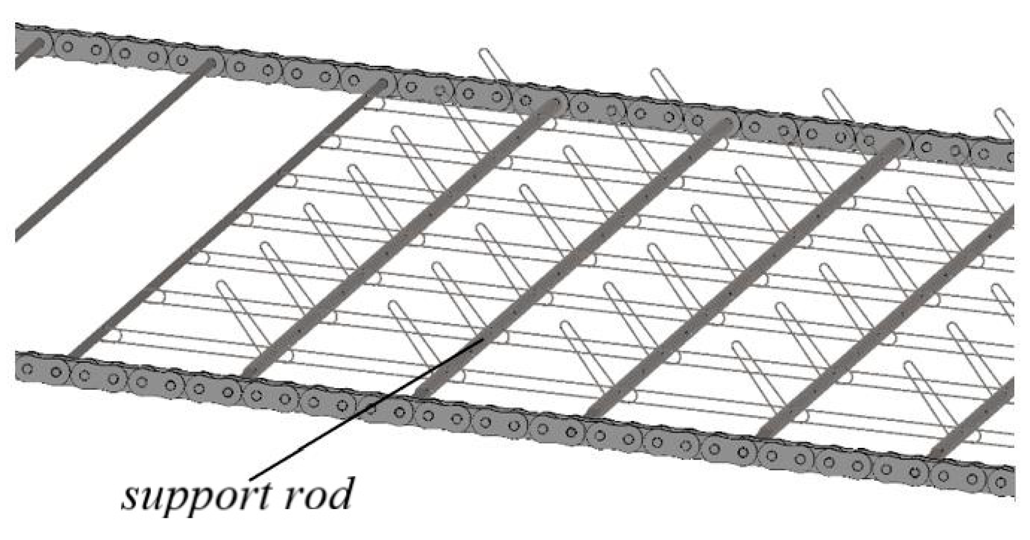
A fully automated aquatic plant combing and clearing machine for river crab farming is developed, which consists of two main parts: an aquatic plant combing and clearing device and a fully automated aquatic plant spreading mechanism. The aquatic plant combing and clearing device comprises a combing mechanism and a water depth adjustment mechanism. The fully automated aquatic plant spreading mechanism includes a drawer-type material warehouse, a material warehouse support, a damping mechanism, a guide rail, a hull, a transmission system, and other components.
(2)
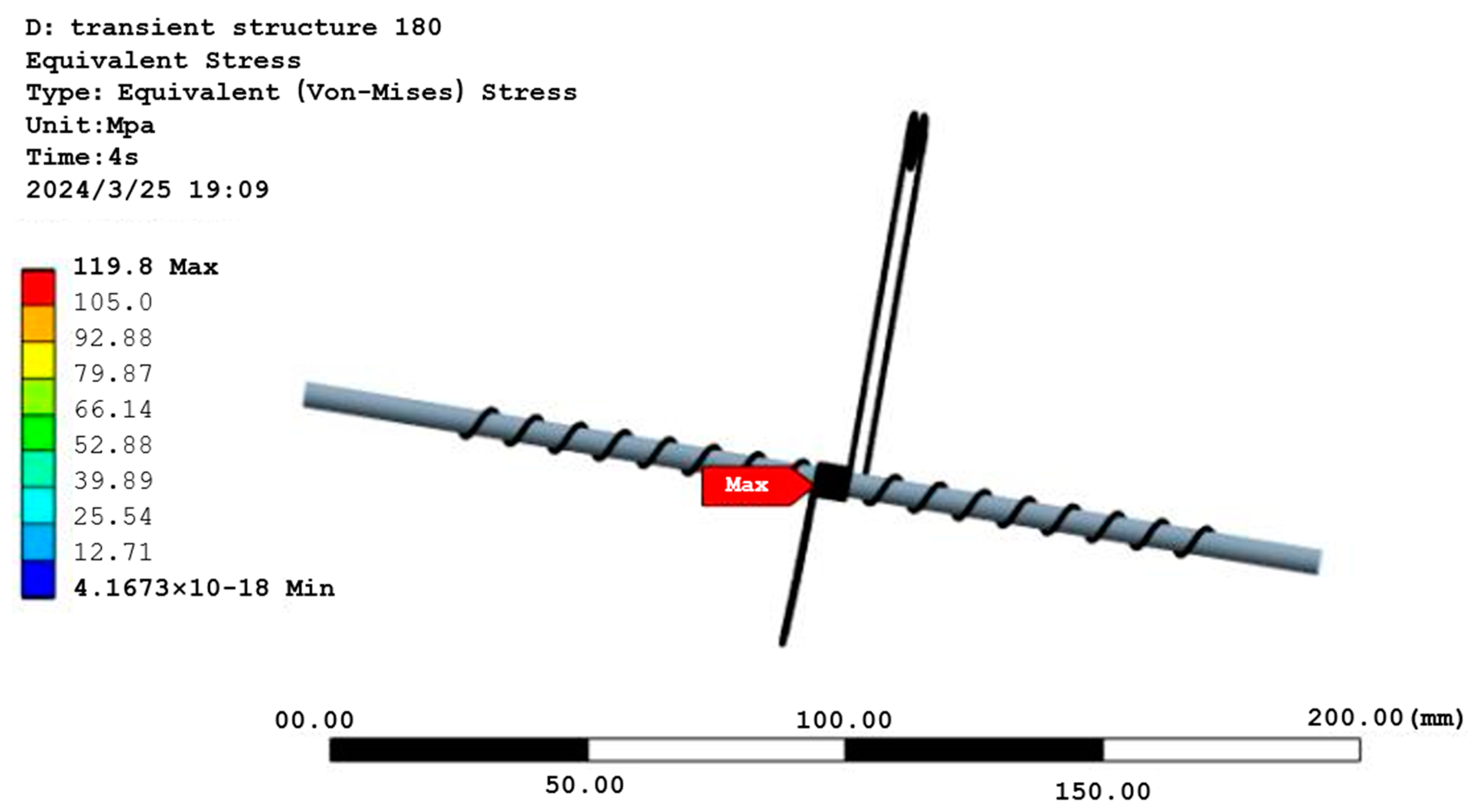
A method for aquatic plant clearing using torsion spring hooks instead of traditional cutting blades is proposed. This method causes minimal damage to the aquatic plant, does not harm the river crabs, and allows for better control of aquatic plant density. The torsion spring hooks were theoretically analyzed and calculated based on the maximum breaking force of the aquatic plant to ensure that they meet the design requirements. Transient dynamics simulations were performed using ANSYS to verify the theoretical calculations. Finally, experimental verification was conducted, and the results showed that the torsion force generated within a certain range of torsion angles can break the aquatic plant, and the torsion spring hooks can avoid obstacles through their own deformation.
(3)
Prototype and Experimental Research: The processing and assembly of the prototype were completed, and basic performance tests as well as comprehensive performance tests in water were conducted. The basic performance test verified that the torsion spring hook can meet the design requirement of breaking off aquatic plants when the torsion angle is less than 20°, and can avoid obstacles through its own deformation. The comprehensive performance tests in water confirmed that the prototype operates smoothly and the stability of water depth adjustment is good. The average clearing efficiency of aquatic plant is 4.92 mu/h, the missed clearing rate of aquatic plants is 0.44%, and the injury rate of river crabs is 0.028%, all meeting the design requirements.
In the future, we can further analyze optimal basic parameters for the torsion spring hook. Orthogonal experiments can be designed for parameters such as the length and initial angle of the torsion spring hook to obtain the best combination of parameters. Machine vision can be incorporated to judge the growth of aquatic plants, thereby automatically adjusting the depth of the clearing mechanism in the water.

Author Contributions

Conceptualization, S.Y. and J.X.; methodology, J.K. and Z.L.; writing—original draft preparation, S.Y.; writing—review and editing, J.K. and H.Y. All authors have read and agreed to the published version of the manuscript.

Funding

This research received no external funding.

Data Availability Statement

Data are contained within the article.

Acknowledgments

The authors thank the anonymous reviewers and journal editor for their valuable suggestions, which helped to improve the manuscript.

Conflicts of Interest

The authors declare no conflicts of interest.

References

  1. Zhang, Z.; Lu, Y.; Li, J.; Zhang, X.; Zheng, P.; Meng, Y.; Luan, K.; Xian, J.; Gu, Z. Research progress of astaxanthin used in culture of shrimp and crab. China Feed 2023, 34, 79–85. [Google Scholar]
  2. Lin, H.; Huang, C.; Pan, J.; Peng, G.; Zhou, J.; Li, X.; Fu, L. The investigation and analysis of cost and benefit of the Chinese mitten crab breeding in Jiangsu province. J. Aquac. 2020, 41, 14–18. [Google Scholar]
  3. Chen, L.; Du, Z.; Hu, Q.; Huang, C.; Li, J. Design and experiment on crab ecological culture system using internal circulation and self-purification in a pond. Trans. Chin. Soc. Agric. Eng. 2021, 37, 227–234. [Google Scholar]
  4. Wang, J.; Liu, Q.; Huo, W.; Han, J.; Liu, T. High Density Breeding Technology of Chinese Mitten Crab and Key Points of Prevention and Control of “Milk Disease”. Mod. Agric. Res. 2023, 29, 128–131. [Google Scholar]
  5. Wu, K.; Ma, X.; Wang, Y.; Wang, W.; Lang, Y. Effect of three water plants decomposition on water quality. J. Shanghai Ocean Univ. 2016, 25, 726–734. [Google Scholar]
  6. Wang, Y.; Shen, W. Harvesting process of aquatic for shrimp-crab-pond. J. Shanghai Ocean Univ. 2011, 20, 938–942. [Google Scholar]
  7. Zhang, G.; Jiang, X.; Cheng, W.; Zhou, W.; Lou, M.; Wu, X. Effect of submerged macrophytes planting mode on performance and economic profit of all-male adult Eriocheir sinensis culture. South China Fish. Sci. 2023, 19, 107–115. [Google Scholar]
  8. Li, Z.; Zhu, H.; Wu, G.; Chen, L.; Chen, Y. Design and test on the navigation control system of the aquatic plants comb collect boat. J. Shanghai Ocean Univ. 2023, 32, 932–942. [Google Scholar]
  9. Chen, H.; Zhou, Y.; Xu, D. Development of A Small-scale Battery-driven Remote-controllable Weed Harvester. J. Anhui Agric. Sci. 2010, 38, 14791–14792. [Google Scholar]
  10. Liu, H.; Zhao, D.; Sun, Y.; Zhang, J.; Wu, B. Control System for Automatic Aquatic Plant Cleaning Ship. Trans. Chin. Soc. Agric. Mach. 2014, 45, 281–286. [Google Scholar]
  11. Hu, Q.; Zhu, H.; Li, J. Research progress and development trend of mechanization of shrimp and crab breeding pond. J. Shanghai Ocean Univ. 2022, 31, 1216–1223. [Google Scholar]
  12. Xu, Y. Design and Experimental Study on Cutting-Transport-Feeding System of Amphibious Aquatic Plants Harvesting Ship; Jiangsu University: Zhenjiang, China, 2019. [Google Scholar]
  13. Kaizu, Y.; Shimada, T.; Takahashi, Y.; Igarashi, S.; Yamada, H.; Furuhashi, K.; Imou, K. Development of a small electric robot boat for mowing aquatic weeds. Trans. ASABE 2021, 64, 1073–1082. [Google Scholar] [CrossRef]
  14. Bian, H. Desing and Research of Deformable Amphibious Cleaup Based on Parallel Mechanism; Shanghai University of Engineering Science: Shanghai, China, 2016. [Google Scholar]
  15. Zhang, L.; Chen, J.; Li, J.; Zhang, Y. Development of SCSGJ-2.6 typeharvester of aquatic weed. J. Northwest A F Univ. 2008, 36, 229–234. [Google Scholar]
  16. Wang, X. Design of a Small Aquatic Cutting Machine; Shanghai Ocean University: Shanghai, China, 2014. [Google Scholar]
  17. Chen, X. Design and Test of Automatic Harvesting Equipment for Water Grass in Crab Pond. Master’s Thesis, Nanjing Agricultural University, Nanjing, China, 2021. [Google Scholar]
  18. Qi, H. Study and Design of Self-Cruising Mowing Boat System for Shrimp and Crab Culture Based on IMU/DGPS; Jiangsu University: Zhenjiang, China, 2021. [Google Scholar]
  19. Rodusky, A.J.; Sharfstein, B.; East, T.L.; Maki, R.P. A Comparison of Three Methods to Collect Submerged Aquatic Vegetation in a Shallow Lake. Environ. Monit. Assess. 2005, 110, 87–97. [Google Scholar] [CrossRef] [PubMed]
  20. Jiang, X.; Huang, Z.; Mu, Y.; He, J. Influence of The Pitch of Cylindrical Spiral Torsion Spring on Rigidity and Stress. Machinery 2021, 59, 47–50. [Google Scholar]
  21. Xu, Z.; Deng, Y.; Zhou, J.; Li, X.; Lu, Q.; Chen, F.; Zhou, G. Structural and functional characteristics of microbial communities in aquaculture ponds of Chinese mitten crab Eriocheir sisensis L. Chin. J. Ecol. 2021, 40, 2223–2233. [Google Scholar]
  22. Liu, L.; Li, J.; Kong, K. Influence of End Fixing Method on Breaking Force of Overhead Insulated Cable. Wire Cable 2024, 67, 40–42. [Google Scholar]
  23. Cheng, D. Mechanical Design Manual, 5th ed.; Chemical Industry Press: Beijing, China, 2016; pp. 11–44. [Google Scholar]
  24. Zhang, H.; Hu, R.; Kang, S. ANSYS 12.0 Finite Element Analysis: From Beginner to Proficient; China Machine Press: Beijing, China, 2010. [Google Scholar]
  25. Li, F.; Zhang, H.; Li, Y.; Zhang, Z. Transient Dynamic Analysis for Cam Mechanism of the Spindle-Picking Cotton. Mach. Des. Manuf. 2013, 51, 128–130. [Google Scholar]
  26. Jiang, H. Study of Fatigue Life and Failure Mechanism of Titanium Alloy Torsion Springs; Shaanxi University of Technology: Xi’an, China, 2022. [Google Scholar]
Figure 1. Amphibious Mowing Boat RS5000.
Machines 12 00639 g001
Figure 2. Mowing Boat TYPE6400.
Machines 12 00639 g002
Figure 3. Overall structure of the fully automatic aquatic plant combing machine for crab farming. 1. Liquid Sensor. 2. Torsion Spring Hook. 3. Support Rod. 4. Travel Switch. 5. Motor. 6. Multi-section Drawer-style Silo. 7. Damping. 8. Hull. 9. Silo Guide Rail. 10. Transmission System.
Machines 12 00639 g003
Figure 4. Workflow diagram of the whole machine.
Machines 12 00639 g004
Figure 5. Analogous design of torsion spring hooks. 1. Limit Ring. 2. Fixed Part. 3. Movable Part. 4. Left Compression Spring. 5. Right Compression Spring. 6. Torsion Spring Part.
Machines 12 00639 g005
Figure 6. Torsion spring hook piece installation.
Machines 12 00639 g006
Figure 7. Operating characteristic curve of the torsion spring hook. φ 1 represents the maximum torsion angle when the torsion spring hook breaks the aquatic plant, and T 1 is the corresponding torque; φ 2 represents the maximum torsion angle when the torsion spring hook encounters obstacles such as aeration pipelines, and T 2 is the corresponding torque; φ l i m represents the limit torsion angle generated by the torsion spring hook, and T l i m is the corresponding torque.
Machines 12 00639 g007
Figure 8. Schematic diagram of force analysis of the torsion spring hook, where φ is the fixed angle of the torsion spring hook, φ 0 is the initial angle, φ 2 is the maximum torsion angle, θ is the angle between the direction of gravity of the obstacle and the Y-axis, F 2 is the rebound force of the torsion spring hook on the obstacle, X is the distance from the obstacle to the center of the torsion spring hook. The dashed line represents the state of the movable part of the torsion spring hook after encountering an obstacle, and the arrow indicates the movement direction of the torsion spring hook. The cross-section of the obstacle is simplified as circular for subsequent calculations. The annotation “fixed” in the figure refers to the movement restriction of the torsion spring hook by the support rod.
Machines 12 00639 g008
Figure 9. Movement diagram of torsion spring hook, where φ is the fixed angle of the torsion spring hook, φ 0 is the initial angle, and φ 2 is the maximum torsion angle.
Machines 12 00639 g009
Figure 10. Basic parameters of torsion spring hook. L : torsion arm. φ 0 : initial angle. D : pitch diameter. D 1 : inner diameter. D 2 : outer diameter. t : Pitch. H : effective length. d : wire diameter.
Machines 12 00639 g010
Figure 11. Finite element simulation model of torsion spring hook.
Machines 12 00639 g011
Figure 12. Element quality of mesh.
Machines 12 00639 g012
Figure 13. Performance testing of torsion spring hooks.
Machines 12 00639 g013
Figure 14. Experimental prototype.
Machines 12 00639 g014
Figure 15. Stress nephogram of the torsion spring hook.
Machines 12 00639 g015
Figure 16. Strain nephogram of torsion spring hook at 135°.
Machines 12 00639 g016
Figure 17. Stress nephogram of the torsion spring hook at 135.
Machines 12 00639 g017
Table 1. SUS304 stainless steel physical performance parameters.
Density ( ρ /kg/cm3)Yield Strength ( σ s /Mpa)Tensile Strength ( σ t /Mpa)Modulus of Elasticity (E/Gpa)Shear Modulus (G/Gpa)Poisson’s
Ratio ( υ )
793025551519382.30.285
Table 2. Permissible stress values for torsion spring materials.
Wire TypeStainless Steel Wire for Springs
Torsion springTest bending stress 0.75 σ b
Static load allowable bending stress 0.68 σ b
Dynamic load allowable bending stressFinite fatigue life ( 0.55 0.65 )   σ b
Infinite fatigue life ( 0.45 0.55 )   σ b
Table 3. Experiment on torsion spring hook at a 20° torsion angle.
Serial
Number
Torsional Force/NMaximum Breaking Force of Aquatic Plant/NDifference/N
118.9416.412.53
218.882.47
319.042.63
418.992.58
518.912.5
618.932.52
719.062.65
818.942.53
919.012.6
1018.962.55
Table 4. Experiment on torsion spring hook at a 180° torsion angle.
Number of TestsFree Angle after Test/(°)Initial Free Angle/(°)Difference/(°)
545450
10450
20450
30450
50450
6045.020.02
7045.020.02
8045.040.04
9045.040.04
10045.080.08
Table 5. Performance test of prototype.
Operational Stability (30 min)Water Depth Adjustment Stability (30 min)No-Load Speed (m/s)Full Load Speed (m/s)Battery Worktime/h
goodgood1.321.057.6
Table 6. Prototype aquatic plant clearing efficiency.
Test PondArea (mu)Clearing Time/hClearing Efficiency/h
Pond 161.234.88
Pond 26.51.314.96
Pond 371.424.93
Average//4.92
Table 7. Missed clearing rate of aquatic plants and injury rate of river crabs.
Test PondNumber of Uncleared Aquatic Plant Stems/m2Number of Injured River Crabs/Crab/muMissed Clearing Rate of Aquatic Plants (%)Injury Rate of River Crabs (%)
Pond 1101.33%0%
Pond 20100.083%
Pond 3000.44%0%
Disclaimer/Publisher’s Note: The statements, opinions and data contained in all publications are solely those of the individual author(s) and contributor(s) and not of MDPI and/or the editor(s). MDPI and/or the editor(s) disclaim responsibility for any injury to people or property resulting from any ideas, methods, instructions or products referred to in the content.

