Article

Dynamics and Failure Analysis on Rigid–Flexible Coupling Structure to Bucket Wheel Stacker Reclaimer

College of Mechanical Engineering, Taiyuan University of Science and Technology, Taiyuan 030024, China
*
Author to whom correspondence should be addressed.
Machines 2025, 13(3), 209; https://doi.org/10.3390/machines13030209
Submission received: 10 February 2025 / Revised: 1 March 2025 / Accepted: 3 March 2025 / Published: 5 March 2025
(This article belongs to the Section Machine Design and Theory)

Abstract

:
The adjustment of counterweights in bucket wheel stacker reclaimers is crucial for the equipment’s load-bearing capacity, vibration, and overall stability. To enhance operational reliability and safety while reducing failure rates and maintenance costs, this study employs finite element analysis (FEA) software and multibody dynamics (MBD) software to develop a rigid–flexible coupling model of the bucket wheel stacker reclaimer. By simulating the excavation forces generated by different materials, the dynamic response of the equipment during operation was analyzed. The results indicate that during the initial startup phase, significant fluctuations in the system’s parameters occur due to vibrations, but these stabilize after 40 s of damping. Comparative analysis of four excavation forces and various counterweight values during the reclaiming process identifies the optimal counterweight as 170 t. The study further reveals that under rotary working conditions, as the excavation force increases, the failure counterweight value increases by 8.3%. This research provides a theoretical basis for optimizing the adjustment of counterweights in bucket wheel stacker reclaimers, guiding operational practices under actual working conditions, ensuring efficient operation across different scenarios, and extending the equipment’s service life.

1. Introduction

A bucket wheel stacker reclaimer is a heavy-duty machine used for large-scale material handling and stacking/reclaiming operations, widely employed in ports, power plants, steel mills, and coal mines. As industries such as mining, metallurgy, and port logistics advance, there is a growing demand for automation and efficiency in material handling equipment. The counterweight block, a critical component of the bucket wheel stacker reclaimer, adjusts the equipment’s center of gravity and balance. Incorrect counterweight values can lead to instability in the pitch structure of the bucket wheel stacker reclaimer, resulting in collapse.
The working environment of the bucket wheel stacker reclaimer has the characteristics of being in the open air, dusty, and noisy, and its high strength operation requires the equipment to have the ability of high load, long continuous operation, and precise operation and to adapt to various harsh climatic conditions. The design and operation of bucket wheel stacker reclaimers must consider multiple factors, including stability, balance, and safety. Compared to other models, rigid–flexible coupling models can simultaneously account for the dynamic characteristics of both rigid and flexible components within the system, effectively predicting responses under extreme conditions and enhancing design reliability and safety. Guo et al. developed a rigid–flexible coupling dynamic model to analyze the dynamic characteristics of the internal combustion engine pushrod valve train system, demonstrating higher precision [1]. Liu et al. proposed a rigid–flexible coupling dynamic analysis method for a mass attached to a massless flexible rod rotating about an axis, discussing the effects of centrifugal force, Coriolis force, and a tangential inertia force on the dynamic response [2]. Gu established a rigid–flexible coupling model of a tower crane system, studied the dynamic characteristics of a composite high-rise structure, and revealed the influence of different parameters on the dynamic response [3]. He used a rigid–flexible coupling approach to simulate bridge vibrations under wind loads, validating its accuracy with SIMPACK and analyzing dynamic indicators under different train and wind speed combinations [4]. Xin developed a rigid–flexible coupling dynamic model of an automobile crane and performed dynamic simulations of the virtual prototype using ADAMS software, analyzing the dynamic characteristics of key components under specific working conditions and providing references for the design of multi-stage flexible telescopic arms [5]. Cao combined the Lagrange method and assumed modes method to establish a rigid–flexible coupling model of a tower crane, analyzing the impact of boom deformation on effective load swing angles through simulation [6]. Wang presented a study on rigid–flexible coupling dynamics, analyzing the interaction between rigid and flexible components. It aimed to enhance system performance, improve reliability, and provide a deeper understanding of the underlying mechanisms in engineering applications [7]. He et al. proposed a marine crane dynamic analysis model based on rigid–flexible coupling virtual prototypes, enhancing analysis accuracy through numerical simulation and experimental validation, aiding offshore crane design [8]. Lai conducted a dynamic analysis of a rotary tiller gearbox using EDEM, ADAMS, and ANSYS. The research investigated the kinematic and dynamic characteristics of the gearbox under working conditions, utilizing simulation results to evaluate performance and optimize the design for improved stability and efficiency [9]. Ren and Zhang conducted an overall impact test on hydraulic supports, studying the response characteristics under dynamic impacts and validating simulation data against experimental data in ADAMS [10]. Xu investigated the nonlinear dynamic response and connector loads of offshore super-large floating structures using ADAMS software. The study identified amplitude death and network cooperation among modules and provided a stability analysis method for predicting nonlinear dynamics based on connector stiffness and wave periods [11].
In view of the analysis of various failure causes, Chatterjee examined the causes of a stacker reclaimer failure at an Indian iron mine through field inspection, mechanical testing, and metallographic analysis, providing preventive recommendations [12]. Araujo analyzed the collapse of an iron ore bucket wheel stacker reclaimer, identifying design and welding defects that led to brittle fractures and catastrophic failure [13]. Guo optimized the hydraulic mechanism of a bucket wheel stacker reclaimer’s luffing mechanism, which had malfunctioned in production, verifying that the improved hydraulic system met production needs by comparing piston speeds under different pressure valve settings [14]. Yao et al. used ADAMS software to model offshore super-large floating structures, analyzing their nonlinear dynamic response and connector loads. It identified amplitude death and module cooperation, offering a new stability analysis method for predicting dynamic behavior based on connector stiffness and wave period [15]. Shen et al. designed and analyzed a flexible bucket wheel reclaimer (FBWR), studying the dynamics and sensitivity of elastic joints to improve bulk material handling efficiency [16]. Yang et al. used a flexible multibody dynamics model to analyze the impact of ground deformation on crawler crane failures, determining rotational speed thresholds to prevent stress and tipping failures [17]. Gao proposed an analytical method for solving the stress intensity factor (SIF) of asymmetrical hole-edge cracks using a successive conformal mapping technique and Muskhelishvili’s complex variable function [18].
Hameed analyzed the failure of an aircraft’s nose landing gear strut during landing using finite element methods and multibody dynamics tools to simulate stress and discovered that improper installation led to overload fractures [15]. Klinger analyzed the fatigue failure of support counterweight tie rods in two cranes of different designs and manufactures due to wind-induced vibrations during shutdowns, verifying through failure analysis and comparative experiments that wind-induced vibrations caused fatigue fractures [19].
This paper establishes a rigid–flexible coupling model for a bucket wheel stacker reclaimer, simulating its slewing and pitching processes, and obtains data on the speed, angular speed, displacement, and forces at various connections of the components. By conducting comparative studies of the dynamic characteristics under different digging forces and counterweight values, the optimal and failure counterweight values were determined.

2. Bucket Wheel Stacker Reclaimer

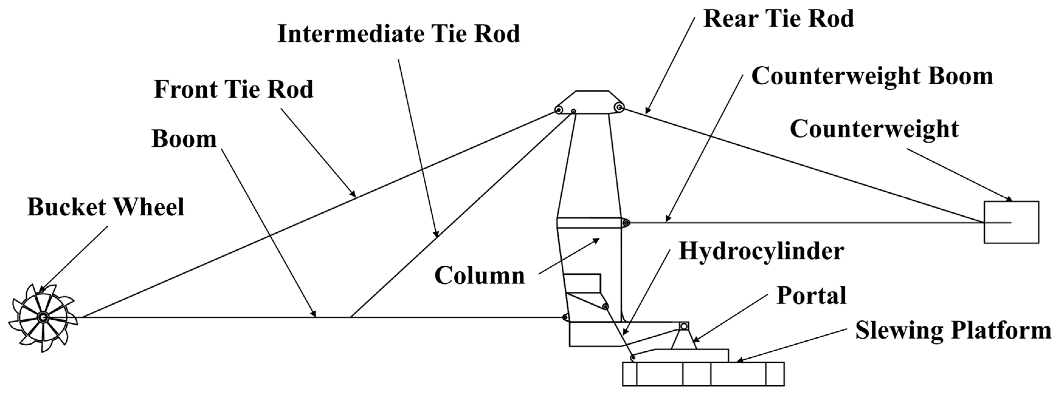
2.1. Introduction of Bucket Wheel Stacker Reclaimer

The stacking and reclaiming mechanism of the cantilever bucket wheel stacker reclaimer is suspended on the cantilever arm, which operates through the rotation and pitching of the cantilever. This design is suitable for long-distance and high-height stacking and reclaiming requirements. The main structure consists of a cantilever belt conveyor, a slewing platform, a pitching mechanism, a bucket wheel mechanism, a tail car transport mechanism, and a traveling mechanism. The structure of the pitch mechanism and the rotary platform is shown in Figure 1. In the bucket wheel stacker reclaimer, the pitch process is realized by driving the luffing cylinder, while the rotary reclaimer relies on the drive of the rotary platform. Due to the structural characteristics of the pitching mechanism, it has a great influence on the stability of the whole machine. As a connector of the front and rear arms, the column has complex stress conditions and is prone to deformation, so it is treated as a flexible body.

2.2. Modeling of Bucket Wheel Stacker and Reclaimer

2.2.1. Establishment of Rigid Body Model

A 3D model of the bucket wheel stacker reclaimer was created using SOLIDWORKS. Due to the column structure being welded from steel plates of varying thicknesses, the model needed to be processed in finite element software by extracting the shell elements from the 3D solid model of the column structure. The model was then imported into the dynamics analysis software in a Parasolid format. Within the dynamics analysis software, material properties were assigned to each part of the structure, and the connections and constraints between various components were established.

2.2.2. Establishment of Flexible Body

The column structure is a core component of the bucket wheel stacker reclaimer’s pitching and slewing operations, with the front and rear arms connecting to the column structure to form an integrated unit. The column is subjected to multiple moments and forces from the front and rear arms. As it is welded from plates of varying thickness and its height significantly exceeds its cross-sectional dimensions, external loads greatly impact its performance. In real operational scenarios, the column structure frequently experiences structural failures, such as plastic deformation due to excessive stress at certain points, leading to stress concentration. Therefore, the column was modeled as a flexible body. After extracting the shell elements, remote points were established at each connection location to add constraint pairs between components, a process performed in ANSYS. The column was discretized into fine meshes in the finite element software, and free modal analysis was conducted. A neutral file was generated, containing reference information for the column, results of each order’s free mode, and the positions of the remote points.
Some of the modal cloud results are shown in Figure 2. The upper and middle regions of the column often show large deformation under multiple modes, indicating that these regions are most prone to deformation under different modes. Although the deformation of the lower region is small, it may also deform significantly in some specific modes. In the subsequent analysis of the dynamic response of the structure, special attention needs to be paid to these deformation-prone areas to ensure the stability and reliability of the structure in practical applications.

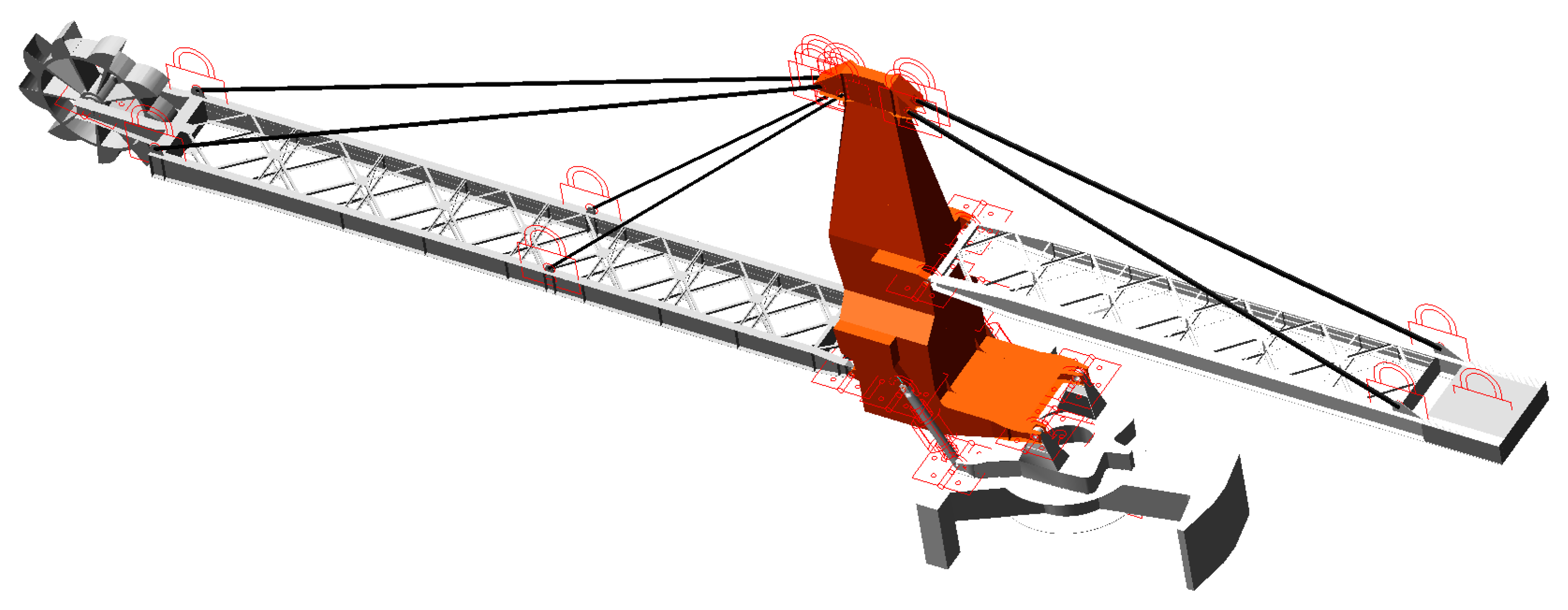
2.2.3. Establishment of Rigid–Flexible Coupling Model

After importing the neutral file into the dynamics analysis software, the flexible body model’s accuracy was validated by comparing the modal values for consistency. Upon verification, dynamic characteristic simulation analysis of the rigid–flexible coupling model was conducted.
To ensure the rigid–flexible coupling model closely approximates the real model, adjustments were made to the connection positions between the rigid and flexible bodies. Appropriate constraints were then applied to connect the rigid and flexible bodies. The corresponding constraints are listed in Table 1.
The constraint connections were completed in ADAMS, resulting in the rigid–flexible coupling model shown in Figure 3.

3. Dynamics Analysis

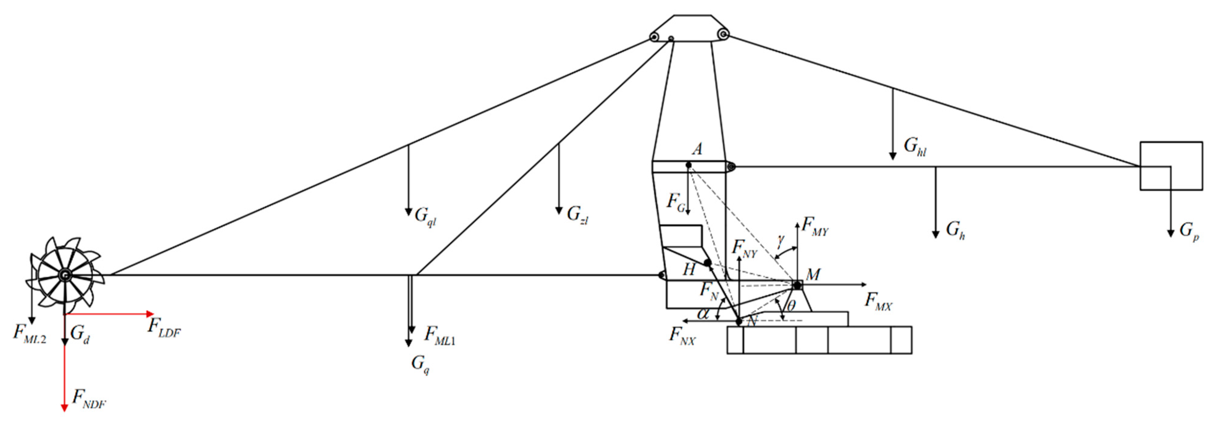
3.1. Column Force Analysis

According to the force analysis in Figure 4 and the lever parameters in Table 2, the moment balance is obtained as follows: According to the stress analysis in Figure 4 and the lever parameters in Table 2, the column moment M A is obtained as follows:
M A = M ,
M A = G q L q + G h L h G q l L q l G z l L z l + G h l L h l G d L d 1 F N D F L d 1 F L D F L d 2 F M L 1 L q F M L 2 L d 1 + G P L P
The meanings of parameters in Formula (2) are shown in Table 3.
In the horizontal unloaded state:
G p L p = G q L q G h L h + G q l L q l + G z l L z l G h l L h l + G d L d 1 ,
In the horizontal fully loaded slewing reclaim state:
G p L p = G q L q G h L h + G q l L q l + G z l L z l G h l L h l + G d L d 1 + F N D F L d 1 + F L D F L d 2 + F M L 1 L q + F M L 2 L d 1
According to Table 2 and Figure 4, the counterweight mass m p can be obtained by the calculation:
m p = 108 + 44.744 F N D F + 423 × L q + 3 × 17.259 × L d 1 L p × g ,
Based on the known relationships, it can be determined that in the horizontal position, HMN = 45.6°, γ 0 = 42.46°, the constant AM = 11,112.61 mm , HM = 6383 mm , and θ = 32.01°. During the pitching motion, the pitching angle range is −12 to 6°. Therefore, it can be derived that:
H M N = 45.6 ° + β ,
γ = γ 0 β ,
H N = H M 2 + M N 2 2 · H M · M N · cos H M N ,
H N M = ar csin ( H M H N · sin H M N ) ,
α = 180 ° H N M θ ,
According to the principle of equilibrium, the cylinder thrust during luffing motion is given by:
F N = F G · sin ( γ · A M ) H M · sin N H M ,
The reaction force at the gantry connection point is given by:
F M Y = F N cos α ,
F M X = F N sin α + F G ,

3.2. Load Calculation

3.2.1. Dead Load DL

According to the different structural dimensions and shapes, the mass of each component is shown in Table 4.

3.2.2. Material Load ML

Material load can be calculated according to Equations (14), (15), (18) and (19) [20].
M L 1 = f Q L g 3600 ν b ,
where M L 1 is the load of the material on the conveyor belt, f is the dynamic load factor taken as 1.1, Q denotes the production capacity, L is the length of the conveyor belt, v b is the conveyor belt speed, and g is the acceleration due to gravity taken as 9.8 m/s². The calculated result is M L 1 = 423 kN. For the simulation, the material mass of 43.17 t is directly calculated in the boom mass.
The material load of a single bucket at full load is calculated as follows:
M L 2 = f V r g ,
where M L 2 is the load of a single bucket when fully loaded, f is the dynamic load factor, V is the bucket capacity, with a theoretical value of 0.88 m³, and r is the material density taken as 2., and M L 2 = 17.259 kN is calculated.

3.2.3. Incrustation Load ICL

The bucket wheel stacker reclaimer is used continuously all year round. There is a certain fouling load on the conveyor belt and the bucket wheel. It is known that the fouling mass on the conveyor belt is 1.8 t, and the fouling mass on the bucket wheel is 6.03 t, which are calculated in the quality of the forearm frame and the bucket wheel, respectively:
I C L 1 = m I C L Q g = 1.8 × 9.8 = 17.64   k N ,
The fouling load on the bucket wheel is calculated as follows:
I C L 2 = m I C L 2 g = 6.03 × 9.8 = 59.1   k N ,

3.2.4. Excavator Force

N D F = f L L ,
where f L is the unit excavation force of different materials, and L is the total length of the cutting edge.
L = 2 n 2 V 0 φ 0 / D φ 0 ,
where n is the number of buckets to be excavated at the same time, V 0 is the theoretical bucket capacity of the bucket, φ 0 is the central angle for bucket wheel cutting, and D is the bucket wheel diameter, where D = 9   m , φ 0 = 90 ° = 0.25 π , V 0 = 0.833   m 3 , and n = 2 . The calculated length L = 211.7   cm .
During the operation of the bucket wheel stacker reclaimer, the bucket wheel is subjected to excavation resistance and lateral excavation resistance, and the lateral excavation resistance is generally 0.3 times the excavation resistance:
L D F = 0.3 N D F ,
According to different materials, the unit excavation force is different, and four kinds of common granular materials are used, corresponding to different excavation forces (NDF), and the lateral excavation force LDF is shown in Table 5.

3.2.5. Digging Force Excitation Frequency Calculation

The periodic excitation frequency of the digging force is determined by the speed of the bucket wheel and the number of buckets. The calculation formula is:
f excitation = n × z 60 ,
The speed of the bucket wheel is 5 rpm, the number of buckets is nine, and the excitation main frequency f excitation obtained by the formula is 0.75 Hz.

3.3. Parameter Settings

Through the analysis of the bucket wheel reclaiming process, it is observed that the number of buckets engaged in material excavation varies continuously during the rotational reclaiming operation. Consequently, the forces acting on each bucket exhibit periodic behavior. Given the different initial positions of each bucket, it is necessary to apply an MOD function with different initial phases to each bucket. With the bucket wheel rotating at a constant speed of 5rpm, excavation resistance (NDF) is applied to bucket 1, as shown in Figure 5a, and the lateral digging force (LDF) is shown in Figure 5b. When a bucket enters the excavation zone, the excavation force and lateral excavation force are applied; when it enters the loading zone, the bucket is subjected only to the load from the mass of the fully loaded material inside.

3.4. Analysis Results of Working Conditions

According to the parameters set in Section 3.2 and Section 3.3, simulations were conducted for both the rotational reclaiming and no-load pitching conditions. Upon completion of the simulations, the relevant results were obtained.

3.4.1. Full-Load Rotary Reclaiming

For the full-load rotational reclaiming condition, the initial value was set to 170 t. This load was then incremented and decremented in steps of 10 t, starting from 170 t, until the maximum stress value exceeded the yield limit, resulting in failure.
Figure 6 illustrates the stress variation over time under four different NDF and LDF conditions for three different counterweight masses. The chart is divided into three sections, each representing a specific counterweight mass. In the first section of Figure 6a, with a counterweight mass of 120 t, the stress values fluctuate significantly throughout the time period, primarily ranging between 120 MPa and 240 MPa. The fluctuation frequency is high, but the amplitude is relatively small, indicating that the stress variation is intense and frequent under this counterweight mass. In the second section, when the counterweight mass increases to 170 t, the stress values still exhibit fluctuations, but the range narrows, primarily between 65 MPa and 85 MPa. The fluctuation frequency is moderate, and the amplitude is relatively moderate as well. The maximum stress value reaches 108.89 MPa. As the curve stabilizes, the stress oscillates around a balanced position of 61.79 MPa, with periodic fluctuations between 68.12 MPa and 58.24 MPa, indicating that the stress variation becomes more stable. In the third section, when the counterweight mass further increases to 210 t, the stress fluctuation amplitude reaches its maximum, ranging from 0 MPa to 413.77 MPa. Although the fluctuation frequency is lower, the amplitude significantly increases, showing that the stress variation, while slow, is considerable.
The trends in Figure 6b–d are generally consistent with those in Figure 6a.
In summary, the stress fluctuation characteristics differ markedly under different counterweight masses. As the counterweight mass increases, both the fluctuation frequency and amplitude of the stress change significantly. These results reveal the impact of counterweight mass on stress distribution and variation during the excavation process, highlighting the importance of counterweight mass on stress values under the influence of excavation forces. Notably, when the NDF is 42,340 N, the LDF is 12,702 N, and the counterweight mass is 170 t. The stress contour of the column is shown in Figure 7.
In Figure 8, it can be observed that under the rotating reclaiming condition, the force curve of the front arm exhibits a clear attenuation trend. Specifically, during the initial phase (0 s to 20 s), the force on the front arm fluctuates dramatically between 2500 kN and 7085.1 kN. This phenomenon is mainly due to the column needing to overcome significant inertia forces at startup, leading to uneven power transmission. As the motion progresses, the impact forces in the system gradually diminish. During the period from 20 s to 60 s, the force fluctuations gradually decrease, indicating that the machine has entered a more stable operating state. Between 60 s and 120 s, the range of force fluctuations narrows to between 3206.42 kN and 4365.71 kN, with a stable value of 3786.06 kN. The force curves of the rear arm and the gantry show a similar attenuation trend to that of the front arm. Additionally, the connection between the column and the cylinder exhibits significant oscillations throughout the simulation, with force values fluctuating between 2500 kN and 5000 kN. The amplitude cylinder experiences a noticeable reduction in force from 0 s to 30 s, and between 30 s and 60 s, the force value gradually stabilizes at 3552.3 kN, fluctuating between 3110.47 kN and 3994.13 kN. These phenomena can be attributed to the flexible nature of the column, which causes various components to experience different degrees of impact and oscillating forces during the rotation process.
Figure 9 depicts the time variation of the vertical displacement of the upright during the rotational process. The displacement increases from −12,580 mm to −12,513 mm. As the rotational angle increases, the slope of the displacement curve gradually becomes steeper, indicating that the rate of displacement change accelerates over time. A zoomed-in view shows that the amplitude of displacement fluctuations gradually decreases while the rate of displacement change accelerates.
The bucket wheel and counterweight are positioned at the two ends of the pitch mechanism of the bucket wheel stacker reclaimer, and they exhibit the highest speeds under any working condition. Figure 10 illustrates the linear velocities of the bucket wheel and the counterweight.
In the initial stage, from 0 s to 10 s, there are significant speed fluctuations. The bucket wheel’s linear velocity reaches a peak of 465.47 mm/s at 2.08 s. After a 30 s attenuation period, the speed fluctuations diminish significantly, stabilizing at 288.12 mm/s. The counterweight reaches its peak velocity of 352.04 mm/s at 0.26 s, following a similar trend as the bucket wheel, eventually stabilizing at 136.24 mm/s.
During the rotation process, the bucket wheel’s angular velocity was set to 5 rpm. However, as shown in Figure 11, the angular velocity experiences significant fluctuations from 0 s to 20 s due to instability during the startup phase. The maximum value reaches approximately 30.42°/s, while the minimum value is about 29.6°/s. After 20 s, the amplitude of these fluctuations decreases significantly, indicating that the angular velocity of the bucket wheel’s center of mass has stabilized during the horizontal material handling process, and the system’s dynamic response has become stable.
Figure 12 illustrates the maximum stress values under four different excavation forces as the counterweight mass varies. The overall trend exhibits a distinct V-shaped pattern, where the maximum stress decreases initially with increasing counterweight mass, then rises again. Specifically, within the range of 120 t to 170 t, the maximum stress shows a significant decrease, with the stress remaining at a relatively low level between 160 t and 180 t. However, once the counterweight mass exceeds 180 t, the maximum stress gradually increases, reaching a higher level at 210 t, surpassing the yield limit of 345 MPa. Although the four curves show some differences in specific values, their general trends are consistent. Overall, the minimum maximum stress occurs around 170 t, while significant increases are observed below 140 t and above 190 t.

3.4.2. Resonance Risk Analysis

The frequency of excavation force may resonate with the first-order modal frequency, which will directly affect the working performance and safety of equipment. Therefore, it is necessary to analyze the relationship between the mining force frequency and natural frequency to verify whether resonance will occur.
According to the classical vibration theory
f n = 1 2 π k / m ,
where k is the equivalent stiffness of the system, m is the total mass, and f n is the natural frequency of the system.
β = f excitation f n ,
where β is the ratio of the frequency of the excitation force to the natural frequency of the system, f excitation is the frequency of the mining force, and f n is the natural frequency of the system. According to the criteria [21], the resonance risk can be ignored when β < 0.7 .
In the study of the dynamic characteristics of construction machinery, the first-order natural frequency of the system, as the lowest-order modal parameter, has a key significance, which not only dominates the overall dynamic response characteristics of the structure but is also the core index to evaluate the resonance risk. The first-order natural frequency of the bucket wheel stacker reclaimer system is shown in Figure 5.
Table 6 of the analysis results shows that as the weight of the counterweight increases from 120 t to 210 t, the first-order natural frequency of the system presents a significant nonlinear attenuation trend from the initial 1.44 Hz to 1.05 Hz, a decrease of 26.9%. This phenomenon reveals that the increase in mass directly leads to the attenuation of natural frequency. It should be noted that with the increase in the counterweight, the ratio of digging force excitation frequency to natural frequency continues to rise from 0.521 to 0.713. When the counterweight reaches 210 t, it exceeds the safety threshold of 0.7, indicating that the system has entered the resonant-sensitive area. According to the criteria [22], when the excitation frequency reaches 70% of the natural frequency of the system, high-order harmonic components and nonlinear effects may cause significant energy coupling, resulting in amplitude amplification and structural fatigue damage.
On the one hand, combined with Figure 12, the counterweight should be strictly controlled within 200 t to avoid the potential failure risk caused by resonance; on the other hand, as shown in Figure 12, the optimal counterweight needs to meet the double standard that the maximum stress value of the structure does not exceed the yield limit of the material and the dynamic response is far away from the resonance region at the same time to realize the global optimization of system safety and operation stability.

3.4.3. No-Load Pitch

During the pitching motion, the amplitude cylinder’s speed is 0.47 m/min. Figure 13a illustrates the stress–time curves at the maximum stress node under unloaded upward pitching conditions with counterweights of 120 t, 150 t, and 190 t. For the 120 t counterweight, the maximum stress fluctuates between 200 MPa and 255.57 MPa after 10 s, with a small stress amplitude, indicating that the stress variation is relatively small and stable at this counterweight level. For the 150-ton counterweight, the initial stress rapidly increases to 217.6 MPa, reaching its peak at 2.53 s. After 10 s, the stress curve shows a decreasing trend, with the overall curve being relatively smooth. Although there are still high-frequency oscillations, the amplitude is small, indicating that the stress on the structure is relatively low and tends to stabilize at this counterweight level. For the 190 t counterweight, the maximum stress fluctuates between 175 MPa and 358.28 MPa, with significant high-frequency oscillations and increased amplitude, indicating more severe stress fluctuations. Figure 13b shows the stress variation under unloaded downward pitching conditions. For the 100 t counterweight, the stress variation trend is similar to that of the 120 t counterweight in Figure 13a; for the 140 t counterweight, although the initial stress is relatively high, the structure gradually stabilizes over time; for the 190 t counterweight, the stress amplitude gradually decreases. These variations in stress under different counterweight conditions clearly demonstrate the impact of load on stress response. As the counterweight value approaches the failure load, the maximum stress experienced by the structure increases, and the frequency and amplitude of stress oscillations also increase.
In Figure 14a, as the machine tilts upward from 0 degrees to 6 degrees, the force at the connection point of the pitch cylinder significantly increases, stabilizing at a peak of 5879 kN. This increase is due to the cylinder having to overcome greater gravitational and inertial forces as the tilt angle rises. The force curve shows considerable vibration, with peak forces continuing to increase over time, although the vibrations gradually stabilize. In contrast, the gantry experiences an initial force of approximately 4935 kN, with the amplitude gradually decreasing and stabilizing after 20 s. These characteristics reveal the system’s response under dynamic loading conditions.
Figure 14b illustrates the process of the machine tilting downward from 0 degrees to −12 degrees. Over time, the force on the pitch cylinder gradually decreases, and the vibration amplitude significantly diminishes. By approximately 120 s, the force drops below 2000 kN, and the amplitude stabilizes. This trend indicates that the system gradually reaches a balanced state after the initial dynamic impact, with oscillations weakening and eventually entering a steady-state phase. In contrast, the gantry’s force curve remains relatively stable throughout the process. Initially, the gantry experiences a force of about 2000 kN, which slightly increases over time, stabilizing around 2500 kN at 120 s.
Throughout the entire pitching process, the pitch cylinder exhibits a distinct initial peak in force, followed by a gradual reduction in oscillations as the system stabilizes. In comparison, the gantry shows relatively stable force variation, with smaller dynamic response changes and faster vibration attenuation. This reflects that the pitch cylinder primarily bears the larger dynamic load, while the gantry demonstrates good structural rigidity and vibration resistance.
Figure 15 and Figure 16 illustrate the time variation of the upright displacement during the upward tilting and downward tilting, respectively. The slope of the curves remains largely constant, indicating a steady rate of displacement change over time. A zoomed-in view reveals that the amplitude of displacement fluctuations gradually decreases, further confirming the stable growth trend in displacement over time.
Figure 17 illustrates the characteristics of the linear velocity variations of the bucket wheel and counterweight under two operating conditions, reflecting the dynamic behavior of the machinery under different loads and motion modes.
In Figure 17a, the linear velocity of the bucket wheel and counterweight decreases from nearly 500 mm/s to approximately 100 mm/s within the first 10 s, then gradually stabilizes, remaining below 100 mm/s. The velocity fluctuations are mainly concentrated between 10 s and 60 s, with a relatively small range. In Figure 17b, the linear velocity of the bucket wheel and counterweight decreases from nearly 500 mm/s to approximately 100 mm/s within the first 20 s. Thereafter, the velocity fluctuations become more pronounced, though they remain below 100 mm/s and slowly diminish. The fluctuations are primarily concentrated between 20 s and 120 s, with a larger range and a longer duration compared to Figure 17a. These observations highlight the different dynamic responses of the system under varying conditions, with significant initial velocity drops followed by periods of stabilization and varying degrees of fluctuation.
Figure 18 shows the relationship between maximum stress and counterweight mass under unloaded upward and downward pitching conditions. The data indicate that as the counterweight mass increases, the maximum stress initially decreases and then increases, forming a U-shaped trend. When the counterweight mass increases from 100 t to 150 t, the maximum stress decreases from 435.78 MPa and 378.4 MPa to 217.5 MPa and 211.04 MPa. However, as the counterweight mass further increases from 150 t to 200 t, the maximum stress rises from 217.5 MPa and 211.04 MPa to 388.41 MPa and 389.29 MPa. When the counterweight mass is between 140 t and 170 t, the maximum stress remains relatively stable, with minimal variation.

4. Conclusions

This study established a rigid–flexible coupling model of a bucket wheel stacker reclaimer to intuitively reflect its dynamic characteristics during full-load rotation and no-load pitching processes. By adjusting the counterweight mass, we determined the optimal and failure values for maximum stress in the upright structure.
(1) According to the dynamic characteristic curves analyzed in Section 3.3, during the initial stage of operation under various working conditions, the forces at the connection points, the speed of the bucket wheel and counterweight, as well as the angular velocity of the bucket wheel, all exhibit significant fluctuations. After approximately 40 s of operation, these parameters gradually stabilize. This reflects the dynamic process from startup to steady operation, indicating that there is some instability during the startup phase;
(2) Under the slewing condition, experimental results under different NDF and LDF conditions show that when the counterweight is set to 170 t, the system is most stable, and the maximum stress on the column is minimized. As the counterweight mass increases or decreases, the maximum stress on the column correspondingly increases. When the NDF increases from 31,755 N to 63,510 N, the critical counterweight value increases from 120 t to 130 t, representing an 8.3% increase. Under the pitching condition, the optimal counterweight value for the system is 150 t, while the failure range occurs below 120 t or above 190 t.
By implementing a rational counterweight design and adjustments, not only can the equipment maintain optimal performance under various operating conditions, but operational efficiency and safety are also enhanced. This conclusion underscores the crucial role of counterweight optimization in ensuring the stability and safety of the equipment.

Author Contributions

Conceptualization, X.W.; methodology, Y.Q.; software, X.W.; validation, X.W., Y.Q. and L.C.; formal analysis, X.W.; investigation, Y.Q.; resources, Y.Q.; data curation, X.W.; writing—original draft preparation, X.W.; writing—review and editing, X.W.; visualization, X.W.; supervision, Y.Q.; project administration, Y.Q.; funding acquisition, Y.Q. All authors have read and agreed to the published version of the manuscript.

Funding

This research received no external funding.

Institutional Review Board Statement

Not applicable.

Informed Consent Statement

Not applicable.

Data Availability Statement

The data presented in this study are available in the article.

Conflicts of Interest

The authors declare no conflicts of interest.

References

  1. Guo, J.; Zhang, W.P.; Zou, D.Q. Development and validation of a rigid-flexible coupled dynamic valve-train model. Proc. Inst. Mech. Eng. Part D J. Automob. Eng. 2012, 226, 94–111. [Google Scholar] [CrossRef]
  2. Liu, Z.F.; Ye, P.; Guo, X.W.; Guo, Y. Rigid-flexible coupling dynamic analysis on a mass attached to a rotating flexible rod. Appl. Math. Model. 2014, 38, 4985–4994. [Google Scholar] [CrossRef]
  3. Gu, J.P.; Qin, Y.X.; Xia, Y.Y.; Jiao, Q.Q.; Gao, H.B.; Zhang, Y.Y.; Zhang, H. Research on Dynamic Characteristics of Composite Towering Structure. Int. J. Appl. Mech. 2021, 13, 2150096. [Google Scholar] [CrossRef]
  4. He, X.H.; Gai, Y.B.; Wu, T. Simulation of train-bridge interaction under wind loads: A rigid-flexible coupling approach. Int. J. Rail Transp. 2018, 6, 274–282. [Google Scholar] [CrossRef]
  5. Xin, Y.; Dong, R.; Lv, S. Dynamic Simulation Analysis of Truck Crane Based on ADAMS. Recent Pat. Mech. Eng. 2023, 16, 94–111. [Google Scholar] [CrossRef]
  6. Cao, X.; Yang, Y.; Wang, W.; Gu, Z. Rigid-Flexible Coupling Dynamic Modeling of a Tower Crane with Long Flexible Boom. In Proceedings of the International Conference on Mechanical Design, ICMD 2017, Beijing, China, 13–15 October 2017; Springer: Singapore, 2018; Volume 55, pp. 39–57. [Google Scholar]
  7. Wang, B.Y.; Liu, Z.Y.; Zheng, P.F. Rigid-flexible coupling dynamic modeling and analysis of dumbbell-shaped spacecraft. Aerosp. Sci. Technol. 2022, 126, 107641. [Google Scholar] [CrossRef]
  8. He, B.; Tang, W.; Cao, J.T. Virtual prototyping-based multibody systems dynamics analysis of offshore crane. Int. J. Adv. Manuf. Technol. 2014, 75, 161–180. [Google Scholar] [CrossRef]
  9. Lai, Q.H.; Yu, Q.X.; Dong, J.Y. Dynamic analysis of rotary tiller gearbox based on EDEM, ADAMS and ANSYS. J. Intell. Fuzzy Syst. 2019, 36, 1153–1160. [Google Scholar] [CrossRef]
  10. Ren, H.W.; Zhang, D.S.; Gong, S.X.; Zhou, K.; Xi, C.Y.; He, M.; Li, T.J. Dynamic impact experiment and response characteristics analysis for 1:2 reduced-scale model of hydraulic support. Int. J. Min. Sci. Technol. 2021, 31, 347–356. [Google Scholar] [CrossRef]
  11. Xu, D.-L.; Dai, C.; Zhang, H.-C. Dynamic simulation and connector’s effect on the response characteristics of multi-modular floating structure using ADAMS. Zhendong Gongcheng Xuebao/J. Vib. Eng. 2018, 31, 456–467. [Google Scholar]
  12. Chatterjee, A.; Das, D. A Review of Bucket Wheel Reclaimer Failure Through Mechanical Test and Metallographic Analysis. J. Fail. Anal. Prev. 2014, 12, 402–407. [Google Scholar] [CrossRef]
  13. Araujo, L.S.; De Almeida, L.H.; Batista, E.M.; Landesmann, A. Failure of a bucket-wheel stacker reclaimer: Metallographic and structural analyses. J. Fail. Anal. Prev. 2012, 226, 94–111. [Google Scholar] [CrossRef]
  14. Guo, Z.; Zhu, X.; Wang, M. Optimization of safety valve block of the pitch mechanism of bucket wheel stacker reclaimer. In Proceedings of the 4th International Conference on Mechanical, Electric and Industrial Engineering, MEIE 2021, Kunming, China, 22–24 May 2021; Volume 1983. [Google Scholar]
  15. Yao, J.; Qiu, X.M.; Zhou, Z.P.; Fu, Y.Q.; Xing, F.; Zhao, E.F. Buckling failure analysis of all-terrain crane telescopic boom section. Eng. Fail. Anal. 2015, 57, 105–117. [Google Scholar] [CrossRef]
  16. Shen, J.H.; Dai, Z.L.; Xiang, L.; Wang, G.X. Stiffness analysis of rotary elastic joint for a flexible bucket wheel reclaimer via theoretical, numerical and experimental methods. Powder Technol. 2024, 432, 119119. [Google Scholar] [CrossRef]
  17. Yang, Q.L.; Qu, F.Z.; Yu, Z.Y.; Xie, Z.Y. Stress and stability analysis of slewing motion for crawler crane mounted on flexible ground. Eng. Fail. Anal. 2019, 105, 817–827. [Google Scholar] [CrossRef]
  18. Gao, H.B.; Qin, Y.X.; Wang, L.H. A Semi-Analytical Solution for the Stress Field and Stress Intensity Factor of Hole-Edge Cracks Using Improved Muskhelishvili Method. Int. J. Appl. Mech. 2024, 16, 2450044. [Google Scholar] [CrossRef]
  19. Hameed, A.; Zubair, O.; Shams, T.A.; Mehmood, Z.; Javed, A. Failure analysis of a broken support strut of an aircraft landing gear. Eng. Fail. Anal. 2020, 117, 104847. [Google Scholar] [CrossRef]
  20. Klinger, C. Failures of cranes due to wind induced vibrations. Eng. Fail. Anal. 2014, 43, 198–220. [Google Scholar] [CrossRef]
  21. ISO 5049:1994; Mobile Equipment for Continuous Handling of Bulk Materials—Safety Code. International Organization for Standardization: Geneva, Switzerland, 1994.
  22. ANSI/ASA S2.62-2009; Criteria for Evaluating Flexible Rotor Balance. Acoustical Society of America: New York, NY, USA, 2009.
Figure 1. Schematic diagram of pitching mechanism and slewing platform structure.
Machines 13 00209 g001
Figure 2. Free-mode nephogram.
Machines 13 00209 g002
Figure 3. Rigid–flexible coupling model.
Machines 13 00209 g003
Figure 4. Pitching structure force diagram.
Machines 13 00209 g004
Figure 5. Bucket 1-excavation force. (a) NDF; (b)LDF.
Machines 13 00209 g005
Figure 6. Maximum stress under different counterweight values under rotary working conditions. (a) The NDF is 31,755; (b) The NDF is 42,340; (c) The NDF is 53,925; (d) The NDF is 63,510.
Machines 13 00209 g006
Figure 7. Stress nephogram of counterweight value of 170 t under rotary working condition.
Machines 13 00209 g007
Figure 8. Stress on each joint of column under rotating conditions.
Machines 13 00209 g008
Figure 9. Displacement of column.
Machines 13 00209 g009
Figure 10. Component speed under rotating conditions.
Machines 13 00209 g010
Figure 11. Angular velocity of bucket wheel under rotating conditions.
Machines 13 00209 g011
Figure 12. The relationship between that maximum stress and the mass of counterweight.
Machines 13 00209 g012
Figure 13. Maximum stress under different counterweight values under pitching conditions. (a) Under upward tilt condition; (b) Under downward condition.
Machines 13 00209 g013
Figure 14. Force on each joint of column under pitching conditions. (a) Under upward tilt condition; (b) Under downward condition.
Machines 13 00209 g014
Figure 15. Displacement of column under upward tilt condition.
Machines 13 00209 g015
Figure 16. Displacement of column under downward condition.
Machines 13 00209 g016
Figure 17. Component speed under pitching conditions. (a) Under upward tilt condition; (b) Under downward condition.
Machines 13 00209 g017
Figure 18. Relationship between maximum stress value and counterweight quality under pitching conditions.
Machines 13 00209 g018
Table 1. Constraint types between components.
Component1Component2ConstraintDegree of Freedom
BoomColumnRevolute1
Counterweight BoomColumnRevolute1
Tie RodColumnFixed0
PortalColumnRevolute1
Hydraulic CylinderColumnRevolute1
Bucket WheelBoomRevolute1
CounterweightCounterweight BoomFixed0
PortalHydraulic Cylinder Revolute1
Cylinder BarrelPiston RodTranslation1
BoomTie RodFixed0
Counterweight BoomTie RodFixed0
PortalSlewing PlatformRevolute1
GroundSlewing PlatformFixed0
Table 2. Length of each arm of pitching structure.
ComponentsBoomCounterweight BoomFront Tie RodIntermediate Tie RodRear Tie RodBucket Wheel
X
Bucket Wheel
Y
Counterweight
L/mm21,25016,70022,43621,87016,53142,500748030,500
Table 3. Calculation parameters.
NameUnitMeaning
F N D F NThe digging resistance of the bucket wheel when digging materials
F L D F NThe lateral digging resistance of the bucket wheel when digging materials
F M L 1 NThe force generated by the material load on the conveyor belt
F M L 2 NThe force generated by the material load in the bucket wheel
G q NGravity of the boom
G h NGravity of the counterweight boom
G q l NGravity of the front tie rod
G z l NGravity of the intermediate tie rod
G h l NGravity of the rear tie rod
G d NGravity of the bucket wheel
G P NGravity of the counterweight
L q mmThe moment arm of the boom
L h mmThe moment arm of the counterweight boom
L q l mmThe moment arm of the front tie rod
L z l mmThe moment arm of the intermediate tie rod
L h l mmThe moment arm of the rear tie rod
L d 1 mmThe moment arm of the bucket wheel in the horizontal direction
L d 2 mmThe moment arm of the bucket wheel in the vertical direction
L P mmThe moment arm of the counterweight
Table 4. Mass of each component of pitching structure.
ComponentsBoomCounterweight BoomFront Tie RodIntermediate Tie RodRear Tie RodBucket WheelBalanced Weight
Mass/t67327.541441.03170
Table 5. The excavation force of the bucket wheel stacker reclaimer.
Material TypeParticle Size (mm) f L   ( N / m ) NDF   ( N ) LDF   ( N )
Sand0.5–950–20031,7559526.5
Limestone0–150150–25042,34012,702
Lignite0–30050–25053,92516,177.5
Coal0–300100–40063,51019,053
Table 6. First-order natural frequency and frequency ratio of system under different weights.
Counterweight (t)First-Order Mode Frequency (Hz) β
1201.4397660.520917982505
1301.3910400.539164941339
1401.3396500.559847721420
1501.2891820.581764250509
1601.2414120.604150757363
1701.1970470.626541814983
1801.1561780.648689042691
1901.1186320.670461778315
2001.0841340.691796401552
2101.0523830.712668296618
Disclaimer/Publisher’s Note: The statements, opinions and data contained in all publications are solely those of the individual author(s) and contributor(s) and not of MDPI and/or the editor(s). MDPI and/or the editor(s) disclaim responsibility for any injury to people or property resulting from any ideas, methods, instructions or products referred to in the content.

