Article

Analysis of Rotor Lamination Sleeve Loss in High-Speed Permanent Magnet Synchronous Motor

1
School of Mechanical Engineering, Jiangsu Ocean University, Lianyungang 222000, China
2
Institute of Engineering Thermophysics, Chinese Academy of Sciences, Beijing 100190, China
3
School of Engineering Science, University of Chinese Academy of Sciences, Beijing 100049, China
4
Hengshui Zhongke Hengfa Power Equipment Co., Ltd., Hengshui 053000, China
*
Author to whom correspondence should be addressed.
Machines 2025, 13(3), 236; https://doi.org/10.3390/machines13030236
Submission received: 10 February 2025 / Revised: 7 March 2025 / Accepted: 11 March 2025 / Published: 14 March 2025
(This article belongs to the Special Issue Analysis, Control and Design of Permanent Magnet Machines)

Abstract

:
This study addressed the challenges of excessive eddy current losses and elevated thermal risks to permanent magnets in titanium alloy rotor sleeves for high-speed permanent magnet synchronous motors (HSPMSMs). Focusing on a 10 kW, 30,000 rpm high-speed motor, we innovatively propose incorporating insulating layers between axially laminated sleeve structures. Current research primarily mitigates eddy currents through the limited axial segmentation of sleeves/permanent magnets or radial shielding layers, while the technical approach of applying insulating coatings between laminated sleeves remains unexplored. This investigation demonstrated that compared with conventional solid sleeves, segmented sleeves, and carbon fibre sleeves, the laminated structure with a coordinated design of aluminium oxide and epoxy resin insulating layers effectively blocked the eddy current paths to achieve a substantial reduction in the sleeve eddy current density. This research concurrently highlights that the dynamic stress response and long-term operational reliability require further experimental validation. Subsequent investigations could explore optimised lamination patterns, parameter matching of insulating layers, and integration with emerging cooling technologies, thereby advancing synergistic breakthroughs in lightweight design and thermal management for high-speed motor rotors.

1. Introduction

High-speed permanent magnet synchronous motors (HSPMSMs), characterised by their compact size, lightweight construction, simple structure, high operational efficiency, and robust reliability, are emerging as ideal drive systems in modern engineering fields, such as new energy vehicles, marine propulsion, nuclear power generation, and S-CO2 power generation, aligning with contemporary demands for energy efficiency, high performance, and low emissions [1,2]. For surface-mounted high-speed permanent magnet motors, permanent magnets (PMs) are inherently incapable of withstanding the substantial tensile stresses generated during high-speed rotation, necessitating protective measures.
Current protection strategies primarily involve high-strength non-magnetic alloys or composite materials, such as titanium alloys or carbon fibre. Titanium alloy sleeves exhibit exceptional mechanical strength and thermal stability, maintaining high durability under high-speed rotation and elevated temperatures. However, the high electrical conductivity of titanium alloys induces significant eddy current losses under high-frequency alternating magnetic fields, exacerbating rotor thermal management challenges. Tong et al. [3] compared sleeves fabricated from carbon fibre and titanium alloys. Their results indicate that carbon fibre sleeves reduce the total rotor eddy current losses but increase the PM eddy current losses compared with titanium alloy sleeves. Approaches to mitigate rotor eddy current losses are categorised into stator-side optimisation and rotor-side regulation: (1) stator-side harmonic suppression methods optimise the air gap magnetic field distribution through active harmonic suppression techniques to weaken harmonic coupling effects on the rotor; (2) rotor-side eddy current blocking methods disrupt eddy current paths via structural modifications or material property adjustments, including axial segmentation of PM sleeves with insulation to interrupt eddy current loops or the use of highly conductive sleeve materials to establish harmonic magnetic shielding layers. Cheng et al. [4] introduced a dual-layer sleeve design, incorporating a high-resistivity ferrite layer between inner and outer sleeves, effectively suppressing high-frequency eddy current losses. Du et al. [5] investigated the impact of the sleeve thickness on rotor eddy current losses by axially segmenting PMs into four sections to disrupt the eddy current paths. Reference [6] validated graphene’s efficacy in shielding harmonic magnetic fields. Studies [7,8,9,10] highlighted the axial segmentation of rotor sleeves to disrupt eddy current paths, thereby limiting rotor temperatures in HSPMSMs. Notably, reference [9] compared axial sleeve segmentation with circumferential PM segmentation via 3D finite element analysis, and thus, demonstrated superior eddy current suppression with combined axial sleeve and circumferential PM segmentation, although it required a higher number of segments. Separately, in [10], two rapid and precise computational methods were proposed for evaluating eddy current losses in axial laminated rotor synchronous reluctance machines; however, these methods did not explicitly address lamination within sleeve components [11]. A sleeve-type tapered slit model was proposed, which provides a straight slot in the sleeve tapered structure to block the high-intensity eddy current path in the stacking direction, increasing the length of the eddy current path in the blocking area and completely blocking the length of the eddy current path in the stacking direction. Compared with the previous model, the eddy current loss was reduced by 57.6%. Ref. [12] measured the electromagnetic properties of rotor component materials in low-temperature environments. A composite structure was applied to the outer side of the permanent magnet, featuring a metallic coating and sleeve. The use of copper shielding or aluminium plating was found to reduce the rotor eddy current losses. Ref. [13] proposes a staggered composite material sleeve to reduce rotor losses. This sleeve was applied to a 90 kW, 16,000 rpm permanent magnet motor and compared with traditional carbon fibre sleeves. The rotor total loss and temperature rise were reduced by 44.5% and 18.7% (25.2 °C), respectively. In [14], a stator overhang structure was applied to an MSTMP machine to suppress the rotor eddy current losses. Ref. [15] investigated modifications to the structure and conductivity of a double-layer fixed sleeve to redistribute the eddy currents, and thus, demonstrated significant effectiveness in mitigating the rotor eddy current losses. Concurrently, ref. [16] introduced a tangential permanent magnet rotor structure to reduce the rotor eddy current losses and improve the YASA machine performance. Ref. [17] proposed a simple yet accurate method to evaluate the effect of circumferential segmentation on permanent magnet loss reduction.
In summary, the existing literature predominantly focuses on eddy current loss reduction through limited rotor sleeve segmentation or radial layering, with minimal exploration of axial insulating layers. This study investigated a 10 kW, 30,000 rpm HSPMSM by evaluating three sleeve configurations: carbon fibre, monolithic TC4 titanium alloy, and a laminated TC4 titanium alloy structure. Adopting the rotor-side regulation approach, the laminated sleeve was axially segmented into slices with alumina insulating layers between the laminations to disrupt the eddy current paths and minimise the losses. A three-dimensional finite element model of the motor was developed using ANSYS 2020R2 software, and rotor eddy current losses were analysed and derived based on the equivalent current sheet principle. The accuracy of the 3D finite element results was validated through comparison with analytical calculations.
This paper is organised as follows: In Section 2, the motor’s specifications are briefly introduced, accompanied by 2D and 3D motor model diagrams. In Section 3, the development of a simplified analytical model for eddy current calculations is presented. Section 4 establishes a three-dimensional finite element model of the motor, focusing on computational results for laminated sleeves and conventional monolithic sleeves. Comparative analyses are provided for the effects of the lamination thickness, insulating layer thickness, and material selection on the eddy current behaviour. In Section 5, the innovations, performance advantages, and potential applications of the novel laminated titanium alloy sleeve are systematically summarised. Current research limitations are clarified, and multidimensional future research directions ranging from parameter optimisation to experimental validation are outlined.

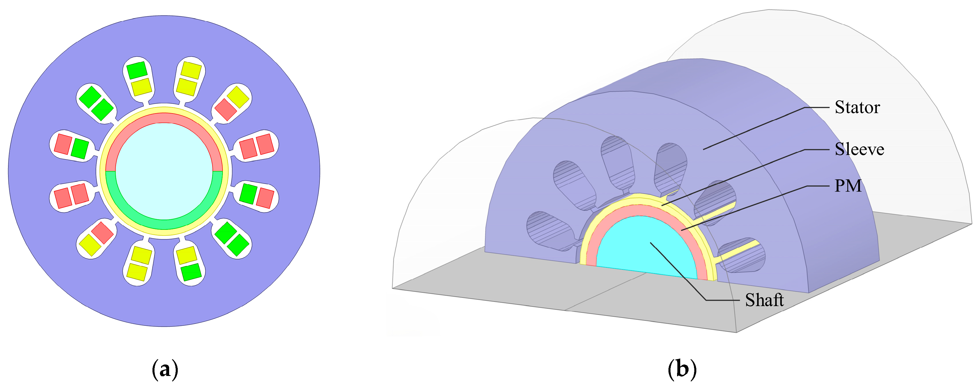
2. Structure and Parameters of HSPMSM

This study investigated the eddy current losses of an HSPMSM rotor sleeve at 10 kW and 30,000 rpm. The HSPMSM comprised a bipolar surface mount rotor structure with titanium alloy sleeves wrapped around the permanent magnets. The motor stator core in this study was composed of 0.2 mm thick B20AV1300 silicon steel sheets. Figure 1a shows the radial cross-section of a 10 kW, 30,000 rpm HSPMSM. The main parameters of the HSPMSM are shown in Table 1. To significantly reduce the computational scale of the 3D model, a half-model was employed, which is particularly advantageous for symmetric structures while simplifying both the boundary condition configuration and post-processing of results. Figure 1b illustrates the three-dimensional half-model of the motor.
For this motor, there were 2 surface-mounted magnetic poles in the rotor, and NdFeB permanent magnets with high magnetism were used. The 2-pole or 4-pole structure could reduce the operating frequency, minimise the eddy current losses in the permanent magnets, and reduce the impact of the current harmonics. In addition, the stator adopted 12 double-layer winding slots, and the stator core used B20AV1300 non-oriented silicon steel sheets to reduce the core losses at high frequencies.

3. Analysis and Calculation of Rotor Eddy Current

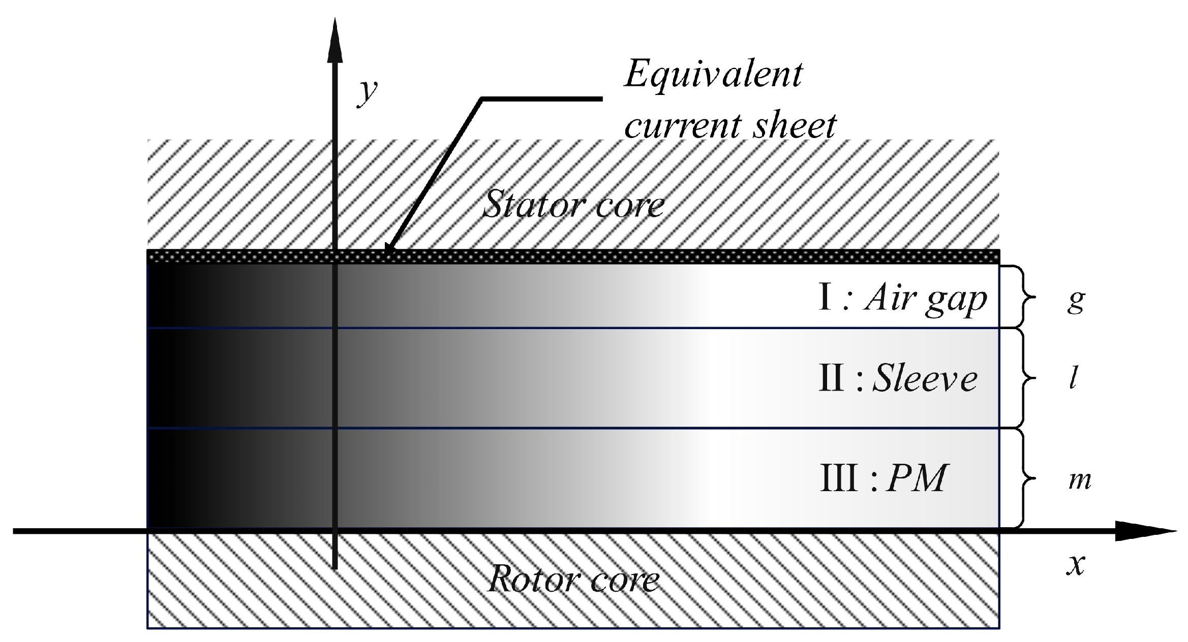
3.1. Simplification of the Analytical Computational Model

To facilitate the development of analytical models, the following simplifications were made [6,18] to the analytical models:
  • The relative permeability and bulk conductivity of the permanent magnet and the sleeve were considered constant and isotropic.
  • The stator winding current was represented by an equivalent current sheet model within the slots.
  • The relative permeability of the stator core was assumed to approach infinity, while its bulk conductivity approached zero.
  • The sleeve, permanent magnet, and air gap computation domains were regarded as semi-infinite planes.
  • The stator slot shape was simplified, with a uniform current distribution within the slots.
  • The effect of the slot opening on the air gap flux density waveform was neglected.
  • End effects were ignored, and only the axial eddy current distribution was considered.

3.2. Establishment of Analytical Model of Rotor Eddy Current Loss

As shown in Figure 2, in the analytical model of this study, the x-axis corresponded to the circumferential direction and the y-axis to the radial direction. The computational domain comprised three layers: an air gap domain with thickness “g”, a sleeve domain with thickness “l”, and a permanent magnet domain with thickness “m”.
The expression for the equivalent current sheet is given as
J ( x , t ) = k = 1 v = J k v sin ( k p ω r t ± v x )
where ω r denotes the rotor speed of the k-th harmonic, p is the number of pole pairs, v represents the spatial harmonic order, and k corresponds to the temporal harmonic order. The amplitude coefficient J k v is defined as
J k v = m N I k k w π R s β , k w = k p k d
where m denotes the number of stator winding phases, N is the number of turns per phase, I k denotes the amplitude of the k-th current harmonic, k p is the pitch factor, k d is the distribution factor, and k w is the winding factor.
By transforming the stator stationary coordinate x to the rotor rotating coordinate x r via x = x r + ω r t p , the equivalent current sheet expression is rewritten as
J ( x r , t ) = k , v Im J k v e j ( k p + v ) ω r t e j β x r
where β = v π τ , with τ representing the fundamental pole pitch.
  • Air gap domain
The axial magnetic potential in the air gap, denoted A g , is governed by Laplace’s equation:
2 A g = 0 2 A g x 2 + 2 A g y 2 = 0
where 2 is the Laplace operator. The general solution takes the form
A g = k = 1 v = γ 0 e β y + γ 1 e β y e j β x r
where γ 0 and γ 1 are constants.
  • Laminated core domain
Each lamination is solved individually, with inter-layer insulation boundary conditions applied. The diffusion equation for the k-th lamination is expressed as
2 A s ( k ) = j ( k p + v ) ω r μ 0 μ s σ s A s ( k )
with the general solution
A s ( k ) ( x , y ) = k , v γ 2 e λ m y + γ 3 e λ m y e j β x
where λ s = β 2 j ( k p + v ) ω r μ 0 μ s σ s , and γ 2 and γ 3 are constants.
  • Permanent magnet domain
To simplify the calculations, this study focused solely on the eddy current losses on the sleeve. By setting σ m = 0 , the analysis contributed only to the static magnetic field:
2 A m = μ 0 × M 0
with the general solution
A m ( x , y ) = k , v γ 4 e λ m y + γ 5 e λ m y e j β x , λ m = β
where γ 4 and γ 5 are constants.
  • Boundary condition configuration
Inter-lamination insulation boundaries:
σ s A s ( k ) y | y = y k + 1 m m = 0   ( Zero   normal   current   component )
1 μ s A s ( k ) y | y = y k + 1 m m = 1 μ s A s ( k + 1 ) y | y = y k + 1 m m   ( Tangential   magnetic   field   continuity )
  • Global boundary at the retaining sleeve
At the permanent magnet–retaining sleeve interface ( y = m ):
A m | y = m = A s ( 1 ) | y = m , 1 μ m A m y | y = m = 1 μ s A s ( 1 ) y | y = m
Retaining sleeve–air gap boundary ( y = m + l ):
A s ( N ) | y = m + l = A g | y = m + l , 1 μ s A s ( N ) y | y = m + l = 1 μ 0 A g y | y = m + l
The single lamination loss is derived as
P k = 1 2 σ s y k y k + 1 0 2 π R A s ( k ) t 2 d x d y = 1 2 σ s V k k , v j ( k p + v ) ω r A s ( k ) 2
where V k denotes the volume of the lamination.
The total retaining sleeve loss is given by
P total = k = 1 n P k

4. Finite Element Simulation

4.1. Model of Lamination Structure Sleeve for Permanent Magnet Motor

To minimise the eddy current losses in the rotor, the titanium alloy sleeve was segmented into multiple axial laminations, separated by 0.05 mm insulating layers to suppress the axial eddy currents. The conventional monolithic sleeve is illustrated in Figure 3a, while the axially laminated sleeve configuration is shown in Figure 3b. Figure 4a presents the radial air gap magnetic flux density distribution of the motor’s 3D model, with a maximum value of 0.832 T, indicating high torque density and uniform flux distribution. Figure 4b displays the magnetic flux density contour map of the stator core, where the stator teeth and yoke exhibited flux densities within the range of 0.5 T to 1.1 T. This confirmed that neither the stator teeth nor the yoke experienced saturation due to an excessive flux density, with uniform flux distribution and minimal leakage. The material parameters of the selected components for the HSPMSM are listed in Table 2.

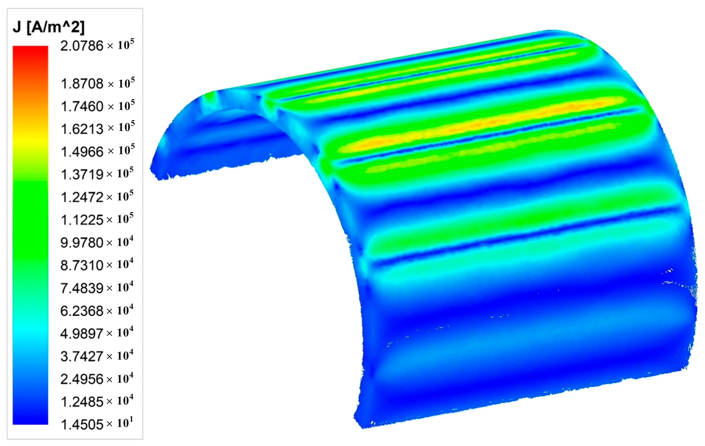
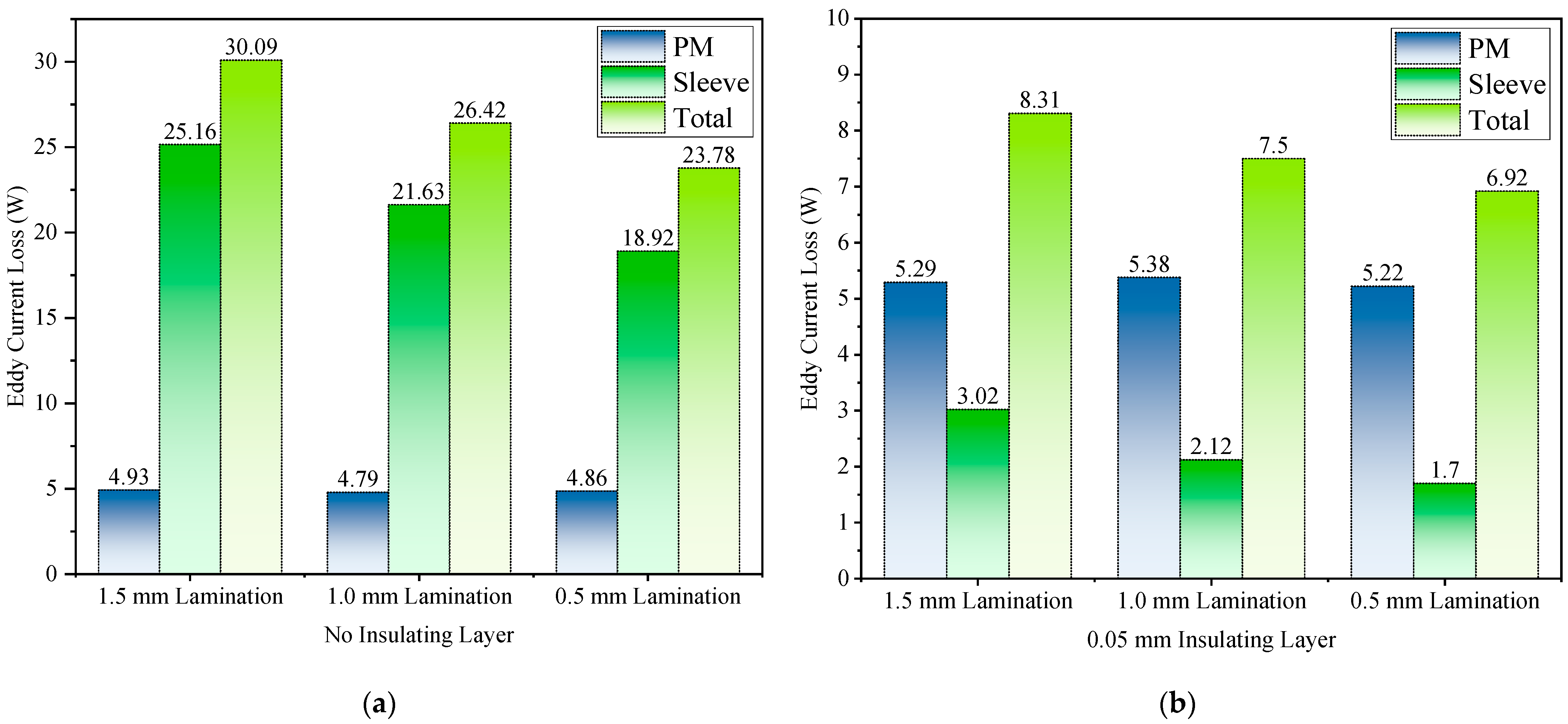
4.2. Finite Element Simulation Analysis

To achieve the precise simulation of eddy current losses in the laminated sleeve structure, a three-dimensional model was developed. The simulation compared two configurations: a monolithic sleeve configuration and an axially segmented laminated sleeve structure with 1 mm slices separated by 0.05 mm insulating layers. Figure 5 illustrates the eddy current density distributions for both configurations: Figure 5a displays the eddy current density distribution in the monolithic sleeve. Long, continuous eddy current paths were observed, resulting in significant circulating eddy currents within the material. Figure 5b shows the eddy current density distribution in the 1 mm axially laminated sleeve structure. In this configuration, the laminations effectively disrupted the eddy current circulation paths within the sleeve, and thus, confined the eddy currents to individual laminated layers and formed distinct stratified loops. As illustrated in Figure 5, the eddy current density of the laminated titanium alloy sleeve under rated operating conditions measured approximately 7.5 × 10⁵ A/m2, representing a reduction of 2.95 × 10⁶ A/m2 compared with conventional sleeves (3.7 × 10⁶ A/m2), which is an approximately one order of magnitude decrease. Figure 6 demonstrates that the carbon fibre sleeve exhibited an eddy current density of 1.6 × 10⁵ A/m2 under equivalent operating conditions, indicating that both sleeve types now operated within fundamentally comparable orders of magnitude regarding the eddy current density.
Figure 7 illustrates the distribution of eddy current losses in the sleeve. Compared with the monolithic structure, the eddy current losses in the laminated structure were significantly suppressed. As evidenced by the comparison between Figure 7a,b, the total eddy current losses in the laminated configuration decreased by approximately one order of magnitude, averaging a reduction from 1.4 × 10⁷ W/m3 to 1.1 × 10⁶ W/m3. This demonstrates the effectiveness of the laminated structure in mitigating eddy current effects. Analytical calculations further validated the simulation results, as shown in Figure 8 and Table 3. The titanium alloy laminated sleeve (Ti Lamination) exhibited significant advantages in eddy current loss reduction compared with both the non-laminated titanium alloy sleeves (Ti No Lamination) and carbon fibre sleeves. The total eddy current losses in the conventional monolithic sleeves approached 50 W, whereas those in the Ti Lamination sleeves were reduced to less than 10 W. This confirms that the laminated design effectively suppressed the eddy currents in the sleeve, which substantially decreased the losses. The conclusions were verified: continuous conductive paths in the monolithic structures resulted in elevated eddy current losses, while the laminated structure confined the eddy currents to smaller loop circuits within individual slices, and thus, achieved a notable loss reduction.
Figure 9 illustrates the effects of the lamination thickness and insulating layer configurations on the rotor eddy current losses. The results demonstrate that (a) the eddy current loss in the non-insulated laminations was significantly higher than that in the (b) 0.05 mm insulating layer group, where the introduction of the insulating layer reduced the loss value by approximately 20 W (a decrease of 22%). This phenomenon could be attributed to the effective enhancement of the inter-lamination resistance by the insulating medium, which suppressed the formation of eddy current circulation by blocking the transverse current paths. Under identical insulation conditions, as the lamination thickness decreased from 1.5 mm to 0.5 mm, the losses exhibited a progressive reduction. This confirmed the optimised mechanism of thin laminations in significantly mitigating the influence of the skin effect by shortening the eddy current paths.

5. Discussion and Conclusions

This study investigated a 10 kW, 30,000 rpm high-speed permanent magnet synchronous motor and this paper proposes an axially laminated titanium alloy sleeve structure. The results demonstrate that the laminated sleeve, which incorporated axial segmentation and an alumina/epoxy resin insulating layer, effectively reduced the rotor eddy current losses. It is particularly notable that the eddy current density of the laminated titanium alloy sleeve under rated operating conditions was approximately 7.5 × 10⁵ A/m2, while that of the monolithic sleeve was approximately 3.7 × 10⁶ A/m2, representing a reduction of roughly 2.95 × 10⁶ A/m2. This value falls within the same order of magnitude as the eddy current density of 1.6 × 10⁵ A/m2 observed in a carbon fibre sleeve under identical conditions. Furthermore, the analysis of varying lamination thicknesses and insulating layer configurations revealed that the introduction of the insulating layer reduced the losses by approximately 20 W (22% reduction). The results confirmed that the insulating layer effectively enhanced the inter-lamination resistance by blocking the transverse current paths, and thus, suppressed the formation of the eddy current circulation. Under identical insulation conditions, a progressive decrease in the lamination thickness correlated with the diminished losses, which further validated the efficacy of the laminated structures in mitigating eddy current effects. The findings underscore the critical importance of material selection and structural design for high-speed motor rotors. This provides a dual-optimisation strategy for laminated structure design: establishing insulating interfaces to enhance the interlayer electrical isolation and minimising the lamination thickness with consideration of the process feasibility. The integrated forming technology of the laminated structure demonstrates significant potential for mass production, enhancing the operational efficiency and thermal stability of permanent magnets in HSPMSMs. Additionally, it provides new avenues for mitigating the permanent magnet temperature rise and achieving rotor lightweighting. However, dynamic stress responses and long-term operational reliability require further experimental investigation. Additionally, in practical engineering manufacturing, titanium alloy sheets can undergo precision machining through laser cutting or waterjet cutting. This is complemented by the application of an aluminium oxide insulating coating via plasma spraying, followed by a final stamping-integrated forming process to balance the structural strength with eddy current suppression requirements.
Future research directions: While this study provided valuable insights, several areas warrant further exploration. Future research could investigate the influence of insulating layer thickness and axial segmentation density on loss characteristics, alongside exploring diverse lamination patterns, orientations, and composite material compositions to optimise the electrical and thermal performance. Additionally, advanced cooling techniques or the integration of thermally conductive fillers in carbon fibre sleeves could address the overheating risks associated with poor thermal conductivity. Dynamic simulations incorporating transient load conditions and mechanical stresses at ultra-high speeds would further enhance the understanding of laminated sleeve behaviour under realistic operating scenarios. Finally, experimental validation of dynamic stress responses and long-term reliability remains critical to ensure the practical viability of this innovative design.

Author Contributions

Y.T. wrote this manuscript; S.L. (Shiqiang Liang) proposed the idea and was responsible for the funding acquisition; F.W., J.T. and K.C. undertook the data curation; S.L. (Shi Liu). reviewed this manuscript. All authors have read and agreed to the published version of the manuscript.

Funding

This research was supported by the Key Research and Development Special Project of the Chinese Academy of Sciences, the National Major Science and Technology Infrastructure Project “High-Efficiency and Low-Carbon Gas Turbine Research Facility” (Grant No. 2017-000052-73-01-001569), the CAS Project for Young Scientists in Basic Research (Grant No. YSBR-043), and the Full-Time Introduction of National High-Level Innovative Talents Project of Hebei Province (Grant No. 2022HBQZYCXY013).

Data Availability Statement

The data presented in this study are available on request from the corresponding author due to privacy.

Conflicts of Interest

The author Shi Liu was employed by the company Hengshui Zhongke Hengfa Power Equipment Co., Ltd. The remaining authors declare that the research was conducted in the absence of any commercial or financial relationships that could be construed as a potential conflict of interest.

References

  1. Xu, Y.; Xu, Z.; Wang, H.; Liu, W. Research on Magnetic-Fluid-Thermal-Stress Multi-Field Bidirectional Coupling of High Speed Permanent Magnet Synchronous Motors. Case Stud. Therm. Eng. 2024, 54, 104012. [Google Scholar] [CrossRef]
  2. Gerada, D.; Mebarki, A.; Brown, N.L.; Gerada, C.; Cavagnino, A.; Boglietti, A. High-Speed Electrical Machines: Technologies, Trends, and Developments. IEEE Trans. Ind. Electron. 2014, 61, 2946–2959. [Google Scholar] [CrossRef]
  3. Tong, W.; Sun, R.; Zhang, C.; Wu, S.; Tang, R. Loss and Thermal Analysis of a High-Speed Surface-Mounted PMSM With Amorphous Metal Stator Core and Titanium Alloy Rotor Sleeve. IEEE Trans. Magn. 2019, 55, 8102104. [Google Scholar] [CrossRef]
  4. Cheng, X.; Xu, W.; Du, G.; Zeng, G.; Zhu, J. Novel Rotors with Low Eddy Current Loss for High Speed Permanent Magnet Machines. Trans. Electr. Mach. Syst. 2019, 3, 187–194. [Google Scholar] [CrossRef]
  5. Du, G.; Wang, L.; Zhou, Q.; Pu, T.; Hu, C.; Tong, J.; Huang, N.; Xu, W. Influence of Rotor Sleeve on Multiphysics Performance for HSPMSM. IEEE Trans. Ind. Applicat. 2023, 59, 1626–1638. [Google Scholar] [CrossRef]
  6. Pan, B.; Tao, D.; Ge, B.; Wang, L.; Hou, P. Analysis of Eddy Current Loss of 120-kW High-Speed Permanent Magnet Synchronous Motor. Machines 2022, 10, 346. [Google Scholar] [CrossRef]
  7. Niu, S.; Ho, S.L.; Fu, W.N.; Zhu, J. Eddy Current Reduction in High-Speed Machines and Eddy Current Loss Analysis With Multislice Time-Stepping Finite-Element Method. IEEE Trans. Magn. 2012, 48, 1007–1010. [Google Scholar] [CrossRef]
  8. Zhang, Y.; Wang, H.; Gerada, C. Rotor Eddy Current Loss and Multiphysics Fields Analysis for a High-Speed Permanent Magnet Machine. IEEE Trans. Ind. Electron. 2021, 68, 5100–5111. [Google Scholar] [CrossRef]
  9. Tong, W.; Hou, M.; Sun, L.; Wu, S. Analysis and Experimental Verification of Segmented Rotor Structure on Rotor Eddy Current Loss of High-Speed Surface-Mounted Permanent Magnet Machine. In Proceedings of the 2021 IEEE International Magnetic Conference (INTERMAG), Lyon, France, 26–30 April 2021; pp. 1–5. [Google Scholar]
  10. Sitnikov, M.A.; Martin, F.; Belahcen, A. Fast and Accurate Methodologies for the Eddy Current Losses Analysis in Axially Laminated Rotor of Synchronous Reluctance Machines under Different Loads. IET Electr. Power Appl. 2024, 18, 995–1004. [Google Scholar] [CrossRef]
  11. Lee, S.-H.; Song, S.-W.; Jeong, M.-J.; Kim, W.-H.; Jung, D.-H. A Novel Sleeve Design to Reduce the Eddy Current Loss of High-Speed Electrical Machines. Machines 2023, 11, 756. [Google Scholar] [CrossRef]
  12. Ge, B.; Yang, Z.; Dong, C.; Liu, J.; Xu, Y. Electromagnetic Property Analysis and Rotor Eddy Current Loss Optimization of Low Temperature and High Speed Permanent Magnet Motor Materials. In Proceedings of the 2024 IEEE 7th International Electrical and Energy Conference (CIEEC), Harbin, China, 10 May 2024; pp. 83–88. [Google Scholar]
  13. Ding, M.; Fang, H.; Qu, R. Reduction of Rotor Loss in High-Speed Electrical Machines With a Novel Composite Sleeve. In Proceedings of the 2023 26th International Conference on Electrical Machines and Systems (ICEMS), Zhuhai, China, 5 November 2023; pp. 78–81. [Google Scholar]
  14. Cui, Z.; Le, Y.; Wang, K.; Wang, H.; Zheng, S. A Low Rotor Eddy Current Loss Design Approach to HSPMSM for Small-Scale Magnetically Suspended Turbomolecular Pump. IEEE Trans. Ind. Electron. 2024, 1–11. [Google Scholar] [CrossRef]
  15. Zhang, J.; Wang, Y.; Ding, H.; Guo, Y.; Sun, Y. Influence of Retaining Sleeve Conductivity and Thickness on Rotor Eddy Current Loss in High-Speed Permanent Magnet Motors. In Proceedings of the 2024 Third International Conference on Sustainable Mobility Applications, Renewables and Technology (SMART), Dubai, United Arab Emirates, 22 November 2024; pp. 1–7. [Google Scholar]
  16. Zhang, W.; Xu, Y.; Xin, F. Comparative Research of Yokeless and Segmented Armature Axial Flux Motors with Surface-Mounted and Tangential Permanent Magnet Rotor. In Proceedings of the 2024 IEEE 21st Biennial Conference on Electromagnetic Field Computation (CEFC), Jeju, Republic of Korea, 2 June 2024; pp. 1–2. [Google Scholar]
  17. Ciriani, C.; Khan, H.A.; Mansour, K.; Olivo, M.; Tessarolo, A. Simple and Accurate Computation of Rotor Eddy-Current Losses in Surface-Mounted Permanent Magnet Machines Accounting for Magnet Circumferential Segmentation. IEEE Access 2024, 12, 36810–36824. [Google Scholar] [CrossRef]
  18. De La Barriere, O.; Hlioui, S.; Ben Ahmed, H.; Gabsi, M. An Analytical Model for the Computation of No-Load Eddy-Current Losses in the Rotor of a Permanent Magnet Synchronous Machine. IEEE Trans. Magn. 2016, 52, 8103813. [Google Scholar] [CrossRef]
Figure 1. (a) Radial sectional view of motor; (b) three-dimensional half-model of motor.
Machines 13 00236 g001
Figure 2. Distribution of the eddy current computational domain along the radial direction of the air gap.
Machines 13 00236 g002
Figure 3. (a) The traditional integral sleeve structure; (b) the axial lamination structure of the sleeve.
Machines 13 00236 g003
Figure 4. (a) Three-dimensional model radial air gap magnetic density; (b) magnetic flux density contour map of the stator core.
Machines 13 00236 g004
Figure 5. Eddy current density distribution contour map of the titanium alloy sleeve: (a) non-laminated structure eddy current density distribution; (b) laminated structure eddy current density distribution.
Machines 13 00236 g005
Figure 6. Eddy current density contour map of the carbon fibre sleeve.
Machines 13 00236 g006
Figure 7. Eddy current loss distribution contour maps of the titanium alloy sleeve: (a) non-laminated structure eddy current loss distribution; (b) laminated structure eddy current loss distribution.
Machines 13 00236 g007
Figure 8. Eddy current losses of three types of rotor components.
Machines 13 00236 g008
Figure 9. Eddy current losses in laminations of different thicknesses: (a) no insulating layer; (b) 0.05 mm insulating layer.
Machines 13 00236 g009
Table 1. Main parameters of the motor.
PropertiesValuePropertiesValue
Rated power (kW)10Stator outer diameter (mm)160
Rated speed (rpm)30,000Stator inter diameter (mm)70
Rated voltage (V)380Core length (mm)60
Pole number2Air gap thickness (mm)2
Stator slots12Sleeve thickness (mm)3
Phase number3PM thickness (mm)5
PM materialNdFe35Frequency (Hz)500
Table 2. Properties of the material.
NameTC4 TiCarbon FibreNdFe35
TangentialRadial
Density (kg/m3)443016507400
Relative permeability1111.058
Bulk conductivity (105 S/m)5.60.30.016.95
Poisson ratio0.340.30.0150.24
Yield/tensile stress (MPa)8251960−10075
Table 3. Comparison of simulation and analytical calculation results for eddy current loss in sleeves with and without lamination.
Finite ElementAnalytical
No Lamination41.64 W45.78 W
Lamination1.82 W2.42 W
Disclaimer/Publisher’s Note: The statements, opinions and data contained in all publications are solely those of the individual author(s) and contributor(s) and not of MDPI and/or the editor(s). MDPI and/or the editor(s) disclaim responsibility for any injury to people or property resulting from any ideas, methods, instructions or products referred to in the content.

