Abstract
The cage strength is a critical factor that constrains performance of high-speed deep groove ball bearing (DGBB) used in the drive motor of new energy vehicles. This paper presents a rigid-flexible coupling dynamic model for high-speed DGBBs, based on interactions dynamic of the flexible crown cage, balls, and rings. This study systematically analyzed the cage weaknesses in strength, and explored how factors such as the pocket clearance, claw length, modification radius and bottom thickness influence cage strength. In addition, an improved design aimed at enhancing cage strength was proposed. The results indicate that the cage strength is more sensitive to the inner-ring speed. Particularly, both the maximum stress and deformation in the radial direction increase sharply when the speed exceeds a threshold of 18,000 r/min. Additionally, an increase in the bearing rotational acceleration leads to a 45.7% rise in the cage stress. Furthermore, the sensitivity of the cage strength to temperature also escalates with bearing speed; the maximum stress and deformation increase by 5% to 16% at 80 °C compared to that obtained at 25 °C. Based on the structural influence on the cage strength, a structural improvement is proposed. With a pocket clearance of 0.23 mm, a claw length of 2.3 mm, a bottom thickness of 2.4 mm, and a shaping radius of 7.0 mm, the strength of the cage was evaluated both before and after the improvements. The results indicated that the enhanced cage exhibited superior strength.
1. Introduction
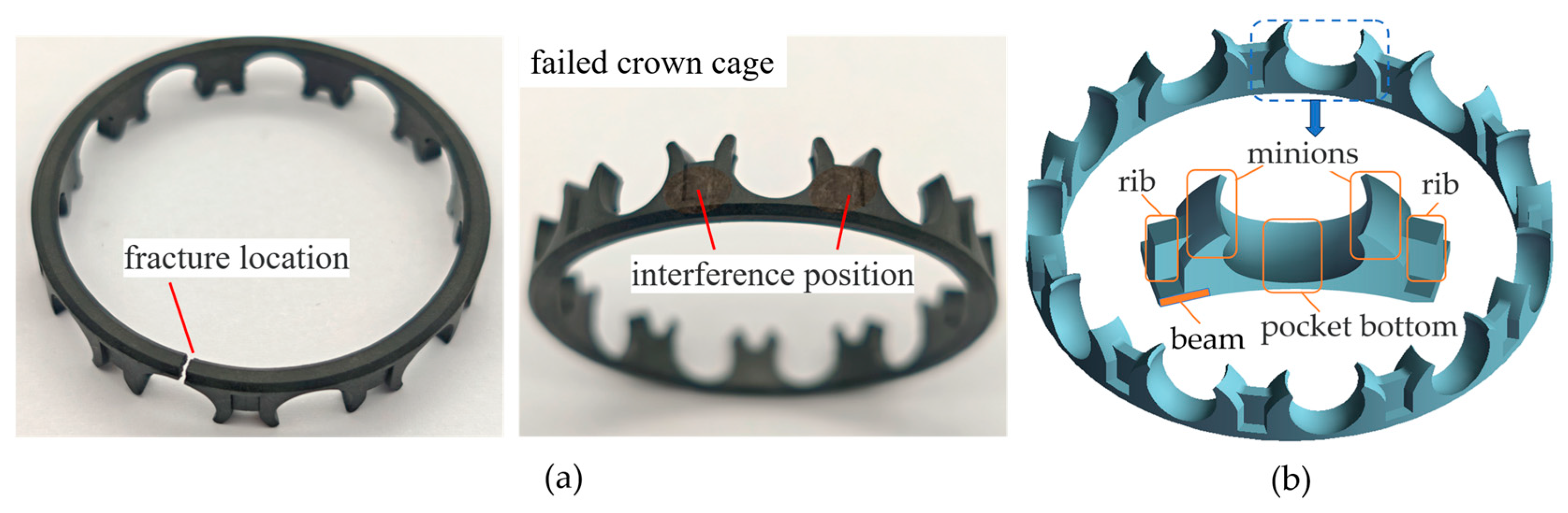
There are several primary reasons for the failure of ball bearings during operation, which primarily include lubrication failure, solid contamination, improper installation, fracture, and wear corrosion. For the deep groove ball bearing inside the driving motor, as the motor drive system continues to evolve and develop, the operating conditions for deep groove ball bearings, which serve as slewing support components, are becoming increasingly demanding. These bearings are required to service under high-speed conditions (n > 1.0 × 106 mm·r/min) and high temperature environments (20 °C~100 °C) [1,2], which may lead to the cage interference with other bearing parts or take place fracture failure [3,4]. Figure 1a illustrates a fracture failure of the crown cage of the DGBB in Motor Drive System of New Energy. The pocket bottom experienced a fracture, and the circumferential surface of the cage shows kinds of interference signs. So, to meet the high speed and temperature conditions for DGBBs in drive motors, cage designs are evolving towards higher strength, reduced weight, and lower friction. The application of nylon material has markedly improved both the cage quality and the friction characteristics of its moving surface. However, the operational performance of the nylon cage in DGBBs is vulnerable to the influence of centrifugal force at high speeds, which may lead to: (1) radial deformation; (2) increased creep; (3) elevated internal stress [5]. Under the influence of centrifugal force, the cage particle is “thrown out” along the radial direction, generating tensile stress internally, which leads to radial expansion deformation [6]. For cages with asymmetrical crown designs, as illustrated in Figure 1b, the axial asymmetry will lead to considerable deformation of the claws and reinforcements. This deformation notably intensifies with increasing distance from the beam’s axial position. Ultimately, it may result in the claw flipping outward, heightening the interference risk between the outer circular surface and the outer ring rib. In addition, since there is less material at the pocket bottom, the risk of breakage at this location increases [7]. Consequently, the strong design of high-speed cages has consistently garnered the attention of scholars and engineers.
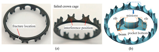
Figure 1.
(a) Interference and fracture of the bearing cage (crown) of the motor drive system. (b) The structure of the crown cage (The blue dash square is the individual pocket of the cage).
Numerous studies have been conducted by scholars on the flexible cages [8]. Li et al. [9] employed orthogonal design to optimize the pocket radius, lock mouth size, and beam thickness of the cage in DGBBs. Shu et al. [10] examined the differences in dynamic performance of bearings by utilizing both flexible and rigid models. They found that the center radius of the cage mass trajectory in the flexible model is smaller. Wang et al. [11] analyzed the interaction mechanisms between the ferrule and other bearing components, concluding that a well-designed flexible deformation can improve the dynamic performance of the bearing. Zhang et al. [12] developed a rigid-flexible coupling multi-body dynamic analysis model for bearings featuring various cage designs under vacuum conditions. Their investigation focused on the effects of rotation speed, cage thickness, and pocket shape on the dynamic characteristics of the cage. Zhao et al. [13] investigated the transient response of the contact impact between the steel ball and the cage, considering various levels of cage flexibility and initial pocket clearance. Liu et al. [14] investigated how radial load, inner ring acceleration, and the connection stiffness between cage mass blocks influence bearing slip. Sadeghi et al. [15] investigated the impact of flexible cages on the dynamic performance of deep groove ball bearings and compared the dynamic results with those of bearings featuring rigid cages. Ashtekar et al. [16] concluded that the flexible cage significantly mitigates the impact strength and sliding of the steel ball. Wang et al. [17] developed a dynamic model for ball bearings and investigated the dynamic characteristics and the mechanisms underlying the unstable rotation of the cage. Su et al. [18] investigated the effects of working conditions and manufacturing errors on the rotational stability and wear degree of the cage. Yao [19] investigated the dynamic responses of contact force, impact force, and motion stability of thin-walled four-point contact ball bearings with crown cages under various load conditions. Zhi et al. [20] established a comprehensive dynamic calculation model for the 6205 integrated bearing and investigated the influence of the pocket clearance in the crown-shaped cage on the vibration characteristics of the bearing. Shuai, G. et al. [21] proposed a crown retainer structure based on US-SCTEB and investigated the dynamic performance of the bearing as well as the motion state of the rolling elements under ultra-high-speed and extreme variable-speed conditions. Cui, Y. et al. [22] investigated the weak points of the cage in response to the issue of rivet fractures in aviation motor bearings and proposed optimization methods for cage design. Taking the angular contact ball bearing H7006C as the research object, Yang, F. et al. [23] investigated the effects of load and speed on the vibration characteristics of the cage by altering the induced slip factor of the bearing. Cui, L. [24] proposed and compared a cumulative fatigue damage rated life model for ball bearings operating under high-speed and light-load conditions, as well as a modified rated life model and a modified reference rated life model under vibrational loading. Zhang, X. et al. [25] characterized the damage characteristic morphology and microstructure at different times regarding the surface damage of hybrid ceramic ball bearings. Fang, B. [26] proposed a comprehensive analytical model for predicting the fatigue life of ball bearings under various working conditions and achieved a more accurate prediction of the fatigue life of ball bearings. Zeng, G. et al. [27] investigated the wear mechanism of high-speed angular contact ball bearings under conditions of quality imbalance, focusing specifically on the plastic deformation of the bearing cage. Researchers have performed a lot of research on flexible cages for ball bearings and introduced relevant research theories and methods, thus, providing valuable experience for the analysis of flexible cages.
However, most of the studies focus on window cages for ball bearings, with limited research investigating the strength sensitivity of crown cages in high-speed DGBBs. It is worth noting that most crown cages are made of lightweight nylon materials [28], and the internal strength of nylon materials is very sensitive to changes in working conditions. Consequently, strength analysis and design of crown cages have become a research focus.
This paper investigates the 6208 DGBBs crown cage, which is commonly employed in the electric drive systems of new energy vehicles, as a case study. The crown cage is constructed from a material consisting of 30% glass fiber reinforced polyamide 46, referred to as PA46 + GF30. This study systematically analyzes the effects of working condition and structural parameters on the sensitivity of cage strength while also considering the dynamic contact relationship between the steel ball and the flexible cage. The resulting influence patterns of cage structural parameters on its strength are identified, along with targeted weak points. An effective structural design plan is proposed, providing a theoretical foundation for the development of lightweight, high-strength, and high-speed cages.
2. Rigid-Flexible Coupling Dynamic Model of Deep Groove Ball Bearings
2.1. Cage Centrifugal Force
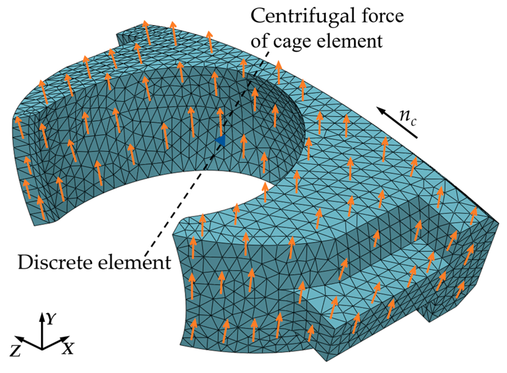
Centrifugal force is generated by the rotation of the cage itself, resulting in tensile stress along the circumferential direction and leading to deformation of the cage. To elucidate the relationship between centrifugal force and bearing speed, the concept of discretization is employed to divide the cage into N discrete elements, each small cube represents a particle within the cage as illustrated in Figure 2. The orange arrows indicate the direction of the centrifugal force acting on each particle as the cage rotates. When the cage rotates around the X-axis at a rotational speed of nc, the centrifugal force is oriented perpendicular to the direction of the linear velocity, each internal particle tends to be “thrown” in the radial (Y) direction, as illustrated in Figure 2.
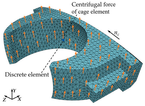
Figure 2.
Discrete crown cage (The orange arrows indicate the direction of the centrifugal force).
Taking the cage element for analysis, the relationship between the centrifugal force and angular velocity is as follows:
In the formula, represents centrifugal force, denotes mass, signifies angular velocity, the relationship between angular velocity, , and rotational speed, n, in s circular motion is , and represents rotation radius.
Assuming that the outer ring of DGBBs remain stationary while the inner ring rotate, and given the working contact angle(α), the relationship between inner ring speed and cage speed can be expressed as follows [29]:
The relationship between the centrifugal force of the cage element and the inner ring speed can be obtained as follows:
In the formula, denotes cage speed, indicates inner ring speed, signifies steel ball diameter, and represents bearing pitch circle diameter.
2.2. Temperature
- (1)
- Cage thermal expansion
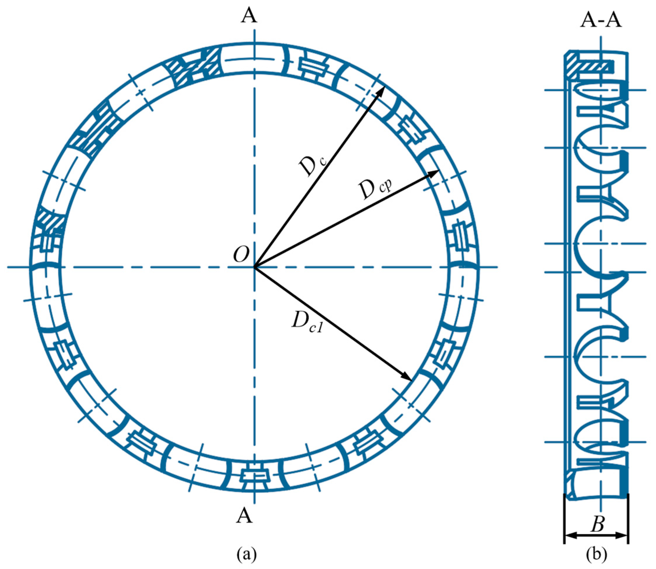
Due to the temperature sensitivity of nylon, the cage is susceptible to thermal expansion under high-temperature conditions, which significantly affects its geometric accuracy and motion state, ultimately compromising its strength. Figure 3 illustrates the schematic diagram of the crown-type cage for the 6208 bearings analyzed in this paper.

Figure 3.
Schematic diagram of the crown cage (a) Front view of the crown cage; (b) Side view of the crown cage.
In a high-temperature environment, the variations in the inner diameter, outer diameter, and pitch circle diameter of the cage can be expressed as follows:
In the formula, represents the coefficient of thermal expansion at temperature, T, represents the temperature difference, and , , and represent the inner diameter, outer diameter, and pitch circle diameter of the cage, respectively.
- (2)
- The impact of lubrication performance
On the other hand, as the temperature increases, the viscosity of the lubricating oil decreases significantly. This reduction in viscosity directly results in changes to the oil film thickness, which in turn affects the load-carrying capacity of the oil film and indirectly influences the strength of the cage. Since the Vogel viscosity–temperature model is applicable over a wide temperature range, the Vogel model is adopted to calculate the viscosity of lubricating oil.
The functional expression of the Vogel model is as follows:
In the formula, denotes dynamic viscosity, A, B, and C indicate undetermined coefficients, and T signifies temperature.
The effect of temperature on density arises from the increase in volume caused by the thermal expansion of lubricating oil, which subsequently leads to a decrease in density. Generally, the impact of temperature on density is minimal and can be disregarded.
2.3. Interaction Between Ball Bearing Components
- (1)
- Normal force between pocket and steel ball
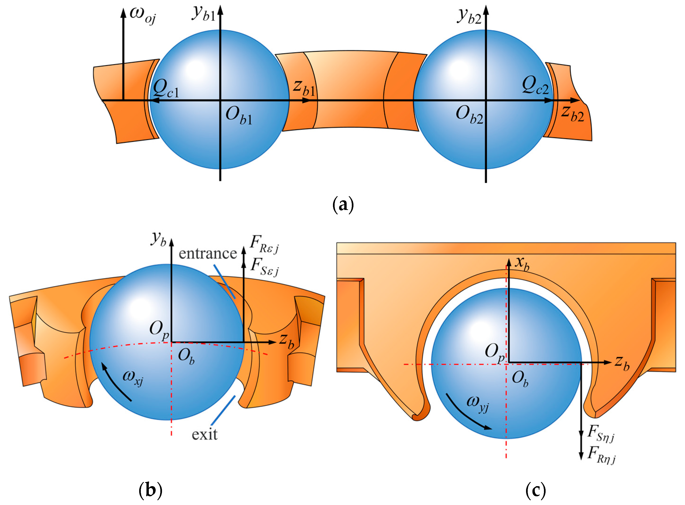
Due to the differing rotational speeds, either the steel ball or the cage may lag behind during the bearing operation. As illustrated in Figure 4a, when the displacement of the steel ball lags, the cage exerts a force on the steel ball (). Conversely, when the cage lags in speed, the steel ball applies a force on the cage (). Considering the elastic deformation that occurs between steel ball and cage, the calculation formula for the normal force is as follows [30]:
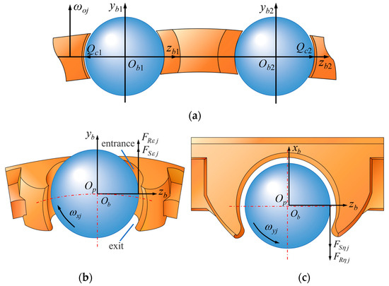
Figure 4.
(a) represents the normal interaction; (b,c) represent the fluid dynamic pressure friction.
In the formula, represents the linear approximation constant, denotes cage pocket clearance, indicates the load–deformation constant at the contact point, and is the pocket center displacement.
- (2)
- Tangential force between pocket and steel ball
When there is a gap between steel ball and cage pocket, the fluid at the entrance of the contact surface is drawn into the moving surface due to the pumping action. This interaction generates both rolling and sliding friction on the steel ball surface, thereby impeding its movement, as illustrated in Figure 4b,c.
The rolling friction force ( and ) and the sliding friction force ( and ) acting on the steel ball surface is formulated as follows [30]:
In the formula, , is the pocket clearance of the jth cage pocket, represents dynamic viscosity of lubricating oils, denotes the drag speed of lubricating oil in the direction, and indicate the effective curvature radius in the and direction, represents the lubricant drag speed in the direction, and and denote relative velocity of steel ball and lubricating oil on pocket surface in the and direction.
- (3)
- The interaction between the cage and the guiding ring
For the cage guided by the outer ring, the interaction between the cage and the guiding ring is generated by the hydrodynamic effect of the lubricant. The resultant force, , acting on the cage generated by the distributed pressure of the hydrodynamic oil film can be described by two orthogonal components, and , as shown in Figure 5.
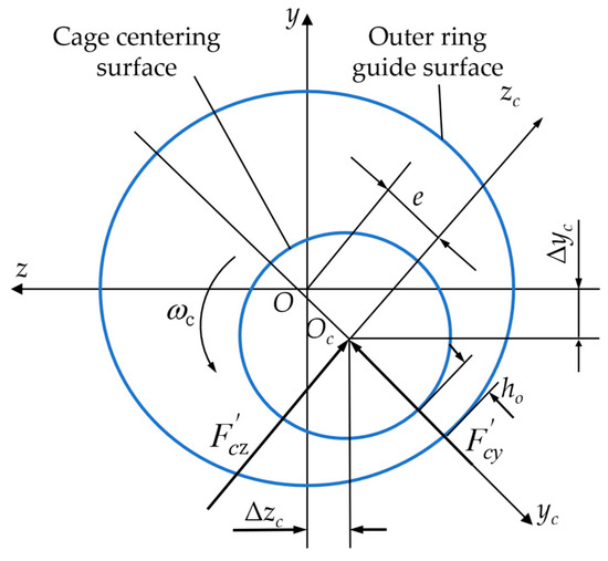
Figure 5.
Geometric configuration of guide ring and cage.
and the acting force can be expressed as follows:
In the equation, L is the width of the cage centering surface, u1 is the dragging speed of lubricating oil, , R1 represents the radius of the centering surface of the cage, C1 denotes the cage guiding clearance, indicates the relative eccentricity of the cage center, , and e is the eccentricity of the cage center.
The distributed pressure of the fluid hydrodynamic oil film also generates the following frictional torque on the surface of the moving cage:
In the equation, is to guide the relative sliding speed between the guide surface and the centering surface.
, , and are calculated in the fixed coordinate system of the cage. When establishing the differential equation of the dynamic motion of the cage, it needs to be transformed into the fixed coordinate system of the bearing:
In the formula, .
2.4. Cage Flexible Body Dynamics Differential Equation
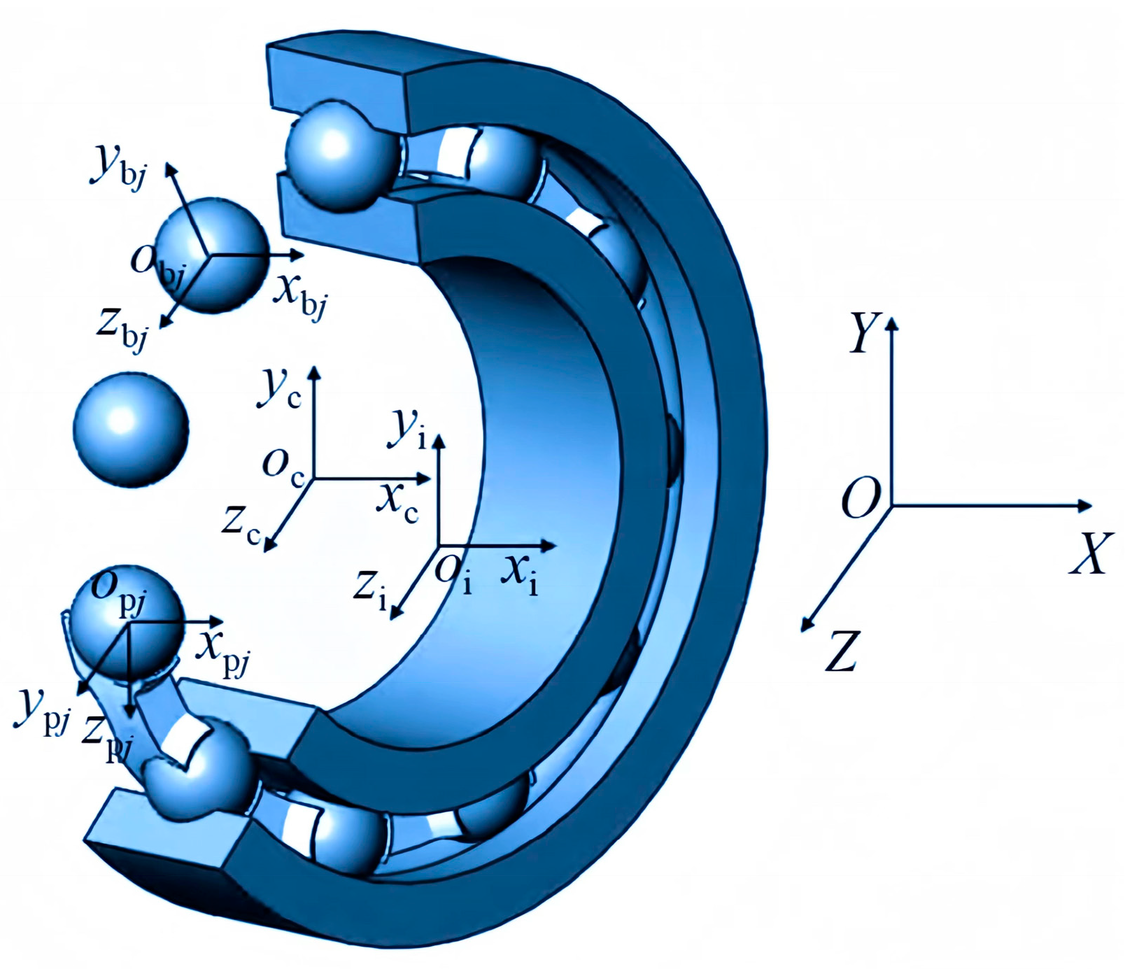
To accurately characterize the motion of flexible cage, determining the bearing coordinate system and establishing the dynamic differential equations of flexible cage is primary. The bearing coordinate system is shown in Figure 6.

Figure 6.
Bearing coordinate system.
- (1)
- The inertial coordinate system {O; X, Y, Z} is fixed in space, with its origin coinciding with the bearing center. The X-axis is aligned with the bearing axis, and the YOZ plane passes through the bearing center while remaining parallel to the bearing radial plane.
- (2)
- The inner ring coordinate system, denoted as {oi; xi, yi, zi}, is defined such that its origin coincides with the centroid of the inner ring. The xi-axis is aligned with the rotational axis of the inner ring, while the yioizi plane passes through the centroid and aligns with the radial plane of the inner ring.
- (3)
- The cage coordinate system, denoted as {oc; xc, yc, zc}, has its origin coinciding with the center of the cage pocket’s center plane. The xc axis is aligned with the cage’s rotational axis, while the yc and zc plane intersects the center of the cage pocket’s center plane and aligns with the cage’s radial plane.
- (4)
- The coordinate system of the j-th cage pocket center, denoted as {opj; xpj, ypj, zpj}, has its origin, opj, coinciding with the center of the cage pocket. In this system, the ypj axis is aligned along the radial direction of the cage, while the zpj axis is oriented along the circumferential direction of the cage. The xpj axis is defined according to the right-hand rule, derived from the ypj and zpj axes. This coordinate system, {opj; xpj, ypj, zpj }, is fixed at the center of the j-th cage pocket and moves in conjunction with the cage. Each cage pocket possesses its own distinct local coordinate system.
- (5)
- The coordinate system {obj; xbj, ybj, zbj} for the center of the j-th ball is defined such that its origin, obj, coincides with the center of the ball. In this system, the ybj axis is aligned with the radial direction of the bearing, while the zbj axis is oriented along the circumferential direction of the bearing. The xbj axis is determined using the right-hand rule based on the orientation of ybj and zbj. This coordinate system { obj; xbj, ybj, zbj} is fixed at the center of the j-th ball and moves in conjunction with the ball, meaning that each ball possesses its own local coordinate system.
Considering that the cage is a flexible structure, the Lagrange equation [30] and the modified Craig–Bampton substructure modal synthesis method [31,32] are utilized to derive the dynamic differential equation of the ball bearing’s flexible cage.
In the formula, represents cage mass matrix; denotes derivative of the mass matrix with respect to time; the subscripts t, r and m are translation, rotation, and modal degrees of freedom, respectively; indicates generalized coordinates, and signifier derivatives of generalized coordinates with respect to time; R is the displacement coordinate, is the Euler angle coordinate, is the modal coordinates, l is the number of modal coordinates; D signifies the modal damping matrix; K represents the stiffness matrix; is the gravity; is the geometric constraints; is the Lagrange multiplier of the constraint equation.
indicates the cage generalized force:
In the formula, is the cage generalized horizontal force; is cage generalized torque; is the cage generalized modal force.
In the formula, is position angle of the jth steel ball; A denotes Euler transformation matrix of the cage stress point coordinate system relative to the global coordinates; B indicates transformation matrix of the resultant moment at stress point of the cage relative to Euler angle coordinate system; and signify modal square matrices of the translational and rotational freedom degrees at the force point, respectively.
By integrating the dynamic differential equation of the flexible cage, as presented in Equation (12), with the dynamic differential equation of the steel ball and inner ring described in the literature [33], we can derive the DGBB rigid–flexible coupling dynamic equation.
3. Model Solving Process
3.1. Modeling and Calculation of Flexible Cage
To accurately analyze the cage dynamic strength, a combined simulation approach is employed, integrating Adams multi-body dynamics with Abaqus (2024 version) finite element software. Develop a parameterized rigid-flexible multibody dynamics simulation module for angular contact ball bearings using the CMD language of the ADAMS system. Based on the previously mentioned interaction model of bearing components, write a subroutine in FORTRAN to calculate the interaction forces between these components and compile it to generate a dynamic link library file that can be linked with the ADAMS solver module. The FORTRAN program reads the system state values at each time step in ADAMS by calling the functional subroutine SYSARY, calculates the initial solution of the dynamics differential equations, and then passes this solution to the ADAMS solver through the array RESULT, thereby completing the integral solution of the dynamics motion differential equations at each step. The process of establishing and calculating flexible cage dynamic model is illustrated in Figure 7a.
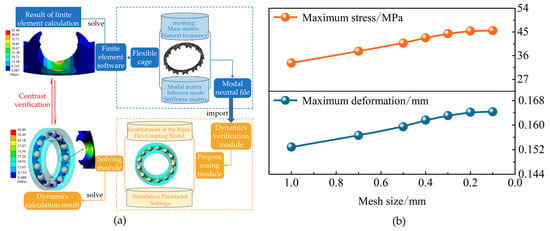
Figure 7.
(a) represents the model solution process and (b) represents the grid size independent calculations.
- (1)
- Firstly, the cage is pre-processed, and then the modal matrix, mass matrix, stiffness matrix, natural frequency, and natural mode of the flexible cage are outputted into a modal neutral file, referred to as the MNF file.
- (2)
- To begin the process, load the Adams/Auto Flex module and import the modal neutral file into Adams/View. Subsequently, create the flexible body and establish the rigid–flexible coupling model. Next, connect the flexible cage with other bearing components using dummy bodies. At this stage, it is essential to restrict the radial translation and the axial and circumferential rotations of the inner ring while permitting other degrees of freedom. Finally, establish constraint forces among the various components of the bearing.
- (3)
- Thirdly, the simulation time is set to 0.5 s, with a step size of 20,000. Additionally, the post-processing panel is established using macro commands within the program. relevant calculation results are extracted during the Adams post-processing stage, and grid-independent calculations are conducted. As illustrated in Figure 7b, the optimal grid size is 0.2 mm.
- (4)
- In the Adams post-processing, the equivalent stress and equivalent strain values at various nodes are obtained. The maximum equivalent stress and the stress contour plots are combined to identify the locations of weak strength in the cage. Meanwhile, perform verification calculations on the cage strength utilizing finite element software to analyze the impact of steel ball collisions on the retainer’s strength.
3.2. Analysis of the Inherent Vibration Characteristics of Flexible Cage
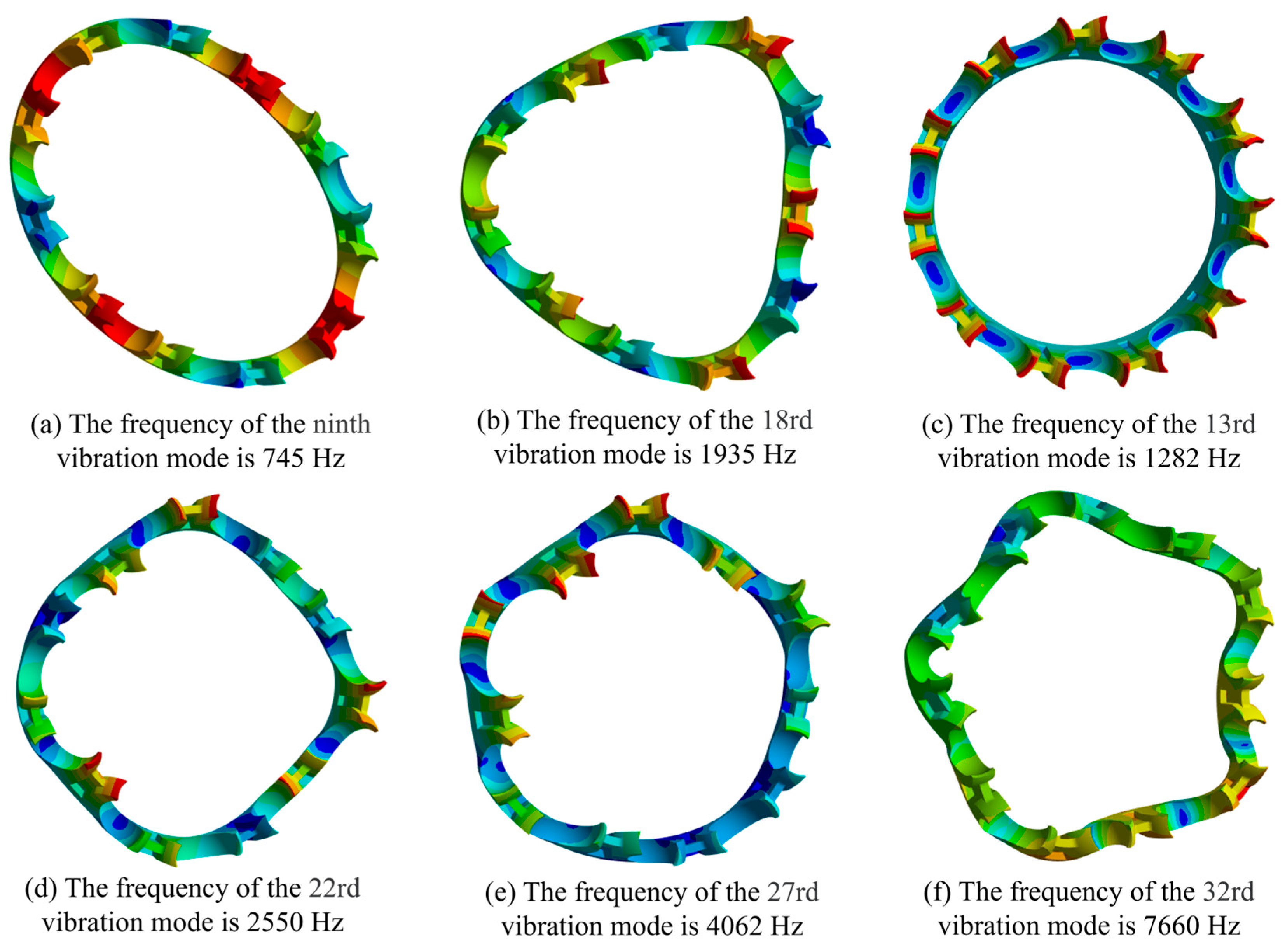
When using the Ansys Workbench module to discretely retain the cage, select the body element and take the 32nd-order mode. Among them, the first 6 orders are rigid modes, and the system automatically cancels its modal mode. The frequency domain corresponding to the remaining 26 flexible modes is 744.96 to 7660.1 Hz. By comparing and classifying the natural modal vibration shapes of the 6th to 32nd orders of the cage, it is found that some modal vibration shapes of the cage appear in pairs. Now list some vibration shapes and natural frequencies in each type (as shown in Figure 8) for analysis.
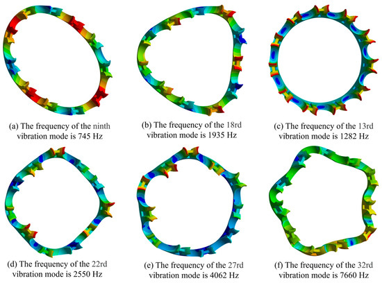
Figure 8.
Vibration mode of the cage.
As illustrated in Figure 8, the 9th and 18th vibration modes correspond to bending vibrations within the ring plane of the cage. Due to the relatively low bending stiffness of the cage in this plane, these modes exhibit low vibration frequencies, making them easily excited in practical applications. The 13th vibration modes represent out-of-plane torsional vibrations of the cage, which can induce shear and tensile effects on the beam. The 22nd and 27th vibration mode pertains to the circumferential expansion and contraction vibrations of the cage, potentially causing local bending of both the beam and the side beam. Lastly, the 32nd vibration mode involves coupled bending and torsional vibrations of the cage in the circumferential direction, resulting in highly complex stress distributions on the cage beam and significantly affecting the strength at the bottom of the cage pocket.
4. Cage Dynamic Contact Simulation
This paper conducts a cage strength sensibility analysis using the widely utilized 6208 bearing, which is commonly found in the drive motors of new energy vehicles, as a case study. The bearing parameters are detailed in Table 1.

Table 1.
Bearing parameters.
4.1. Working Condition Parameters
- (1)
- External load
Within the time frame of 0 to 0.5 s, the Adams (2017 version) software was utilized to calculate the equivalent stress and strain of the cage under varying axial and radial loads. The maximum values of equivalent stress and strain for each working condition were subsequently extracted. It can be seen that increasing the radial load results in a corresponding increase in both the cage equivalent stress and strain from Figure 9a. Conversely, the increase in axial load causes the cage equivalent stress and strain to gradually decrease.
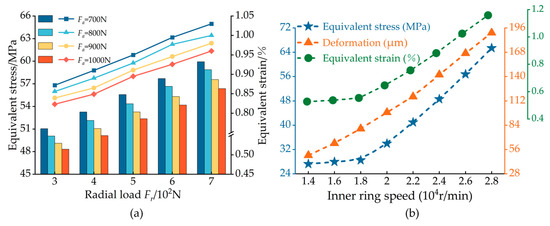
Figure 9.
(a) represents Influence of external load and (b) represents inner ring speed on cage strength.
An increase in radial load leads to a reduction in the rotational speed of the steel ball within the load-bearing area, thereby diminishing its effectiveness in guiding the cage. Simultaneously, the rotational speed of the cage in the non-load-bearing area also decreases, resulting in an increased slip rate of the cage. Consequently, the frequency of hole collisions intensifies, leading to elevated values of equivalent stress and strain. The axial preloading force limits the axial deflection of the steel ball; an increase in this axial preloading force leads to a decrease in axial deflection. Consequently, this reduction minimizes the collisions between the steel ball and the pocket, thereby enhancing the cage strength.
- (2)
- Steady state speed
Figure 9b illustrates the effect of varying inner ring speeds on the cage strength while Figure 10a presents the temporal change curve of the equivalent stress for the jth cage pocket under three different inner ring speeds. In Figure 10a, Adams addresses the steady state of a system with a constant speed of the inner ring. Initially, the speed of the inner ring increases rapidly, resulting in a significant rise in the equivalent stress of the cage. During the interval from 0 s to 0.5 s, the equivalent stress of the cage fluctuates due to the effects of the cage’s inherent slippage and the collisions of the balls. By comparing (a) and (b) in Figure 9, it can be concluded that the sensitivity of the cage strength to the rotational speed is greater than that of the external load.

Figure 10.
(a) represents Stress time domain diagram and (b) represents acceleration conditions.
The dot plots and the histogram are equivalent strain and equivalent stress results in Figure 10a.
It is noteworthy that, as can be seen from Figure 9b, when the inner ring speed exceeds 18,000 rpm, the equivalent stress and deformation of the cage both increase significantly. Furthermore, a substantial increase in the inner ring speed leads to a continuous rise in the amplitude of the equivalent stress experienced by the cage. As the inner ring speed increases, the centrifugal force exerted on the cage also increases, leading to greater deformation of the claw section. Simultaneously, the increase in the inner ring speed exacerbates the tendency of the steel balls to be ejected outward. This intensifies the radial effect of the steel balls on the cage. Consequently, both the maximum value and the variations in the equivalent stress of the pocket increase correspondingly.
- (3)
- Acceleration and deceleration
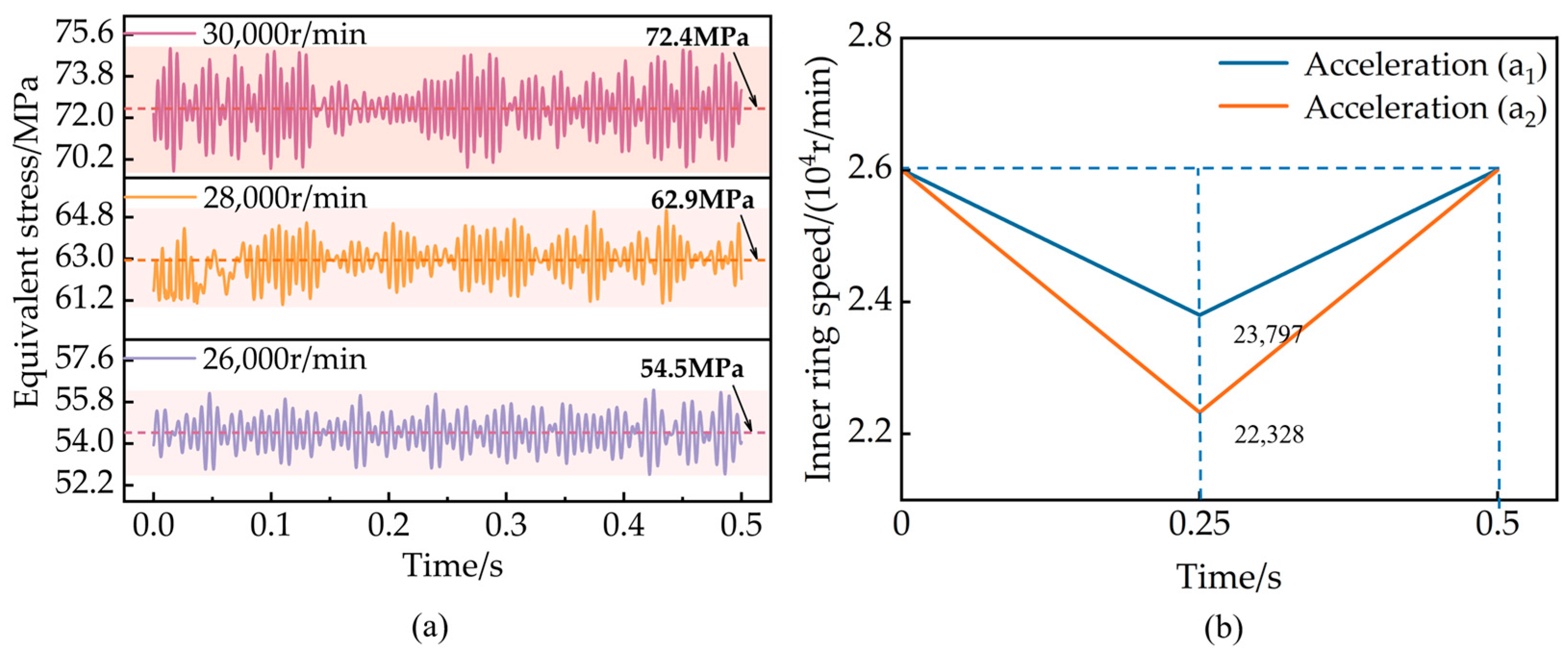
Due to the specific operating conditions of the drive motor bearings, they are often accompanied by phases of rapid acceleration and deceleration. To investigate the cage strength during acceleration and deceleration, the bearing working conditions shown in Table 1 and Figure 10b were used for simulation calculation of the cage.
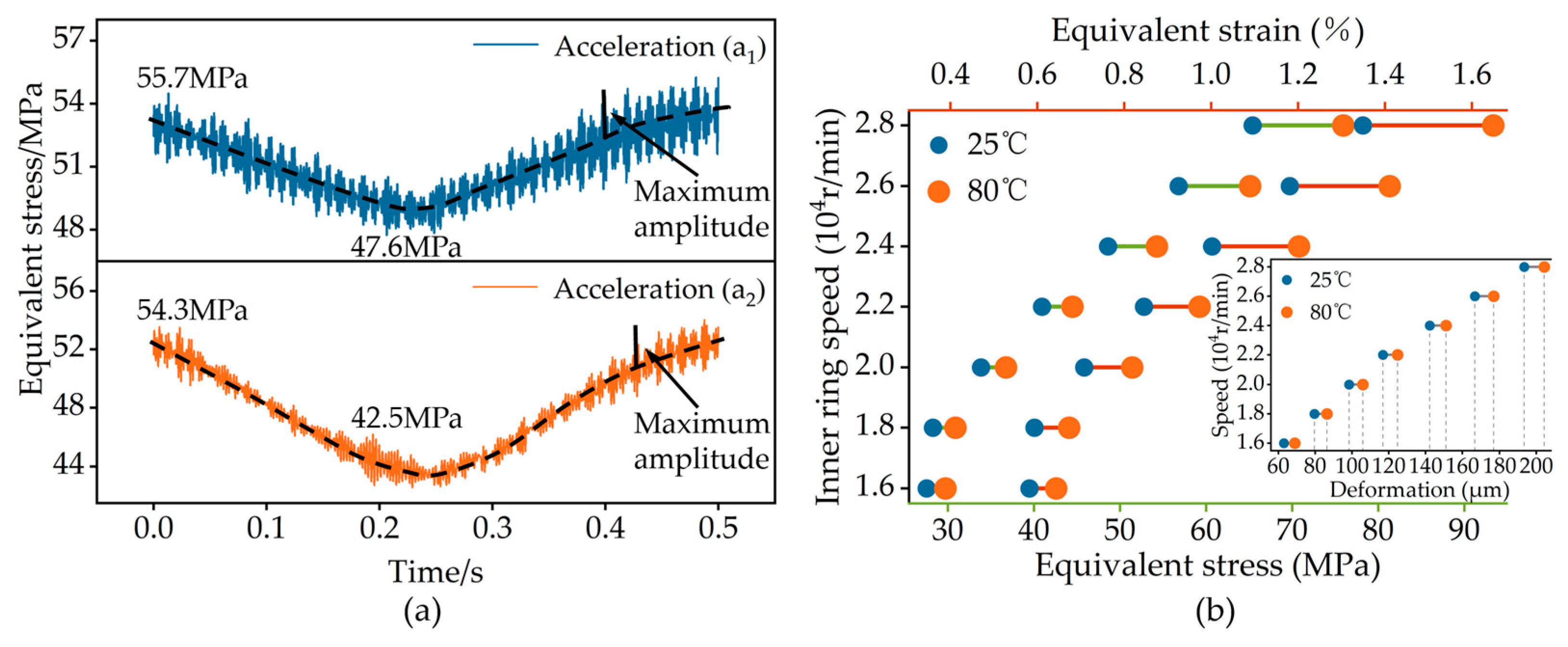
Similarly to the speed simulation described in Section 2, the inner ring speed instantaneously increases from 0 to 16,000 rpm at the initial moment, leading to an unstable state of bearing motion. Consequently, the results of this process are omitted, with the analysis focusing on the acceleration and deceleration conditions illustrated in Figure 10b. Figure 11a illustrates that during the time interval from 0 to 0.25 s, the average equivalent stress of the cage decreases as the rotational speed diminishes. Conversely, from 0.25 to 0.5 s, the average equivalent stress increases in response to an increase in rotational speed. During the time interval of 0~0.25 s, the maximum stress calculated with an inner ring acceleration of a2 is slightly greater than a1. However, there is no significant difference in the maximum amplitude in the two accelerations.
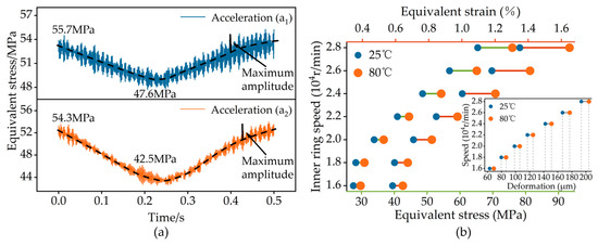
Figure 11.
(a) represents time domain diagram of cage stress (the black dotted line represents the average value of the equivalent stress); (b) represents the effect of temperature on cage strength.
The inner ring acceleration primarily influences the cage strength by altering the cage rotation speed. This change in rotation speed subsequently leads to a corresponding variation in the cage stress. Furthermore, a more rapid change in rotation speed results in a more pronounced alteration in stress. The stress amplitude is primarily influenced by the interaction between the steel ball and the cage, while the effects of acceleration and deceleration are relatively minor.
- (4)
- Temperature
Figure 11b demonstrates that when the bearing’s inner ring rotates at a constant speed, the pocket stress and claw deformation at an operating temperature of 25 °C are lower than those at 80 °C. Furthermore, the sensitivity of cage strength to temperature progressively increases with higher rotational speeds. As the rotational speed rises, the difference in cage strength between the two temperatures becomes more pronounced.
The elastic modulus of PA46 + GF30 material is 6000 MPa at 25 °C and decreases to 5000 MPa at 80 °C. When the bearing load and speed are fixed, the centrifugal force received by the cage and the force between the steel ball and the pocket remain unchanged. However, due to the low elastic modulus, the resistance to deformation is minimal, leading to increased stress, strain, and deformation within the cage. Furthermore, the increase in rotational speed results in a heightened centrifugal force acting on the cage, which in turn amplifies the interaction force between the steel ball and the pocket. Therefore, the higher the speed, the stronger the sensitivity of the cage strength at the same temperature.
4.2. Cage Structural Parameters
It can be drawn from Section 4.1 that the claws deformation and the stress state at the pocket bottom are critical factors influencing the cage strength. This section takes the working condition parameters shown in Table 1 as an example and analyzes the effects of varying claw lengths, pocket gaps, and bottom thicknesses on cage strength, providing data to support the subsequent design plan for cage strength structure.
- (1)
- Pocket clearance
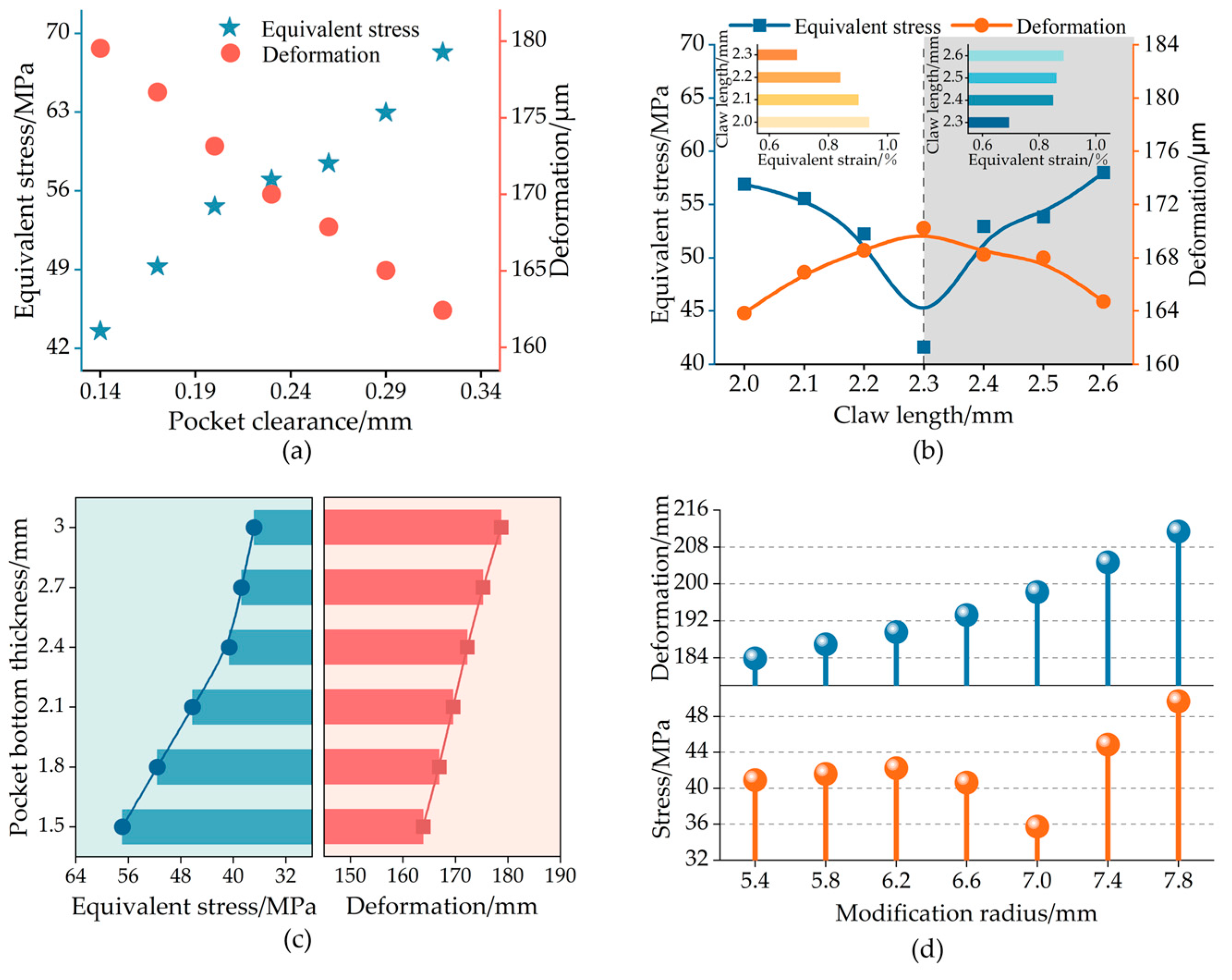
It is evident that as the pocket clearance increases, the stress at the pocket bottom increases, while the claw deformation decreases from Figure 12a. An increase in the pocket clearance results in a rise in the cage speed deviation ratio, a decrease in cage motion stability, and an intensification of collisions between the steel ball and the pocket. This sequence of events leads to increased cage stress and a downward trend in claw deformation. Conversely, when the pocket clearance is excessively small, the pockets become susceptible to radial expansion due to the centrifugal force. This expansion may cause the pocket to contract, adversely affecting the normal operation of the steel ball. When the pocket clearance is 0.22~0.24 mm, the cage strength is better.
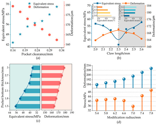
Figure 12.
Effects of the structural parameters on cage strength.
- (2)
- Claw length
Figure 12b indicates that as the claw length increases, both the equivalent stress and equivalent strain of the cage initially decrease before subsequently increasing. However, the claw deformation exhibits an opposite trend, first increasing and then decreasing. Notably, when the claw length is 2.3 mm, the cage experiences the lowest stress, with a minimum value of 41.63 MPa, along with the smallest equivalent strain, recorded at 0.69%. Conversely, the deformation reaches its maximum value of 170.23 μm at this claw length.
The increase in claw length reduces the distance between the axial mass center of the cage and the pocket center, thereby enhancing the stability of cage operation. In addition, it diminishes the force exerted by the steel ball on the pocket, leading to a decreasing trend in stress and strain. However, the increased claw length enhances the claw’s flexibility, resulting in an upward trend in deformation. However, when the claw becomes excessively large, the axial mass center of the cage shifts, increasing the force of the steel ball on the pocket. Furthermore, an excessively long claw alters the stiffness of the claw, leading to a decreasing trend in deformation.
- (3)
- Pocket bottom thickness
It is evident that as the pocket bottom thickness increases, the equivalent stress decreases from Figure 12c. However, this decreasing trend gradually slows down at a thickness of 2.4 mm, and the claw deformation shows an increasing trend.
An increase in pocket thickness enhances the cage stiffness, thereby improving its capacity to resist deformation. Although the internal force per unit area within the pocket diminishes, excessive pocket thickness may cause the axial mass center of the cage to shift further from the pocket’s center, which can reduce the running stability of the cage and intensify the interaction between the steel ball and the pocket. Furthermore, the increased pocket thickness contributes to a rise in the cage mass, which elevates the centrifugal force and exacerbates the claws deformation.
4.3. Cage Strength Design Direction
- (1)
- Design direction
The analysis presented above indicates that the pocket bottom represents the weakest point in the cage, rendering it susceptible to breakage under severe working conditions. Consequently, when designing a cage structure, it is essential to enhance the pockets’ strength and mitigate the effects of centrifugal force on the cage. This section will discuss two key considerations in the design of high-speed cage strength.
- (2)
- Improve the strength of the pockets bottom
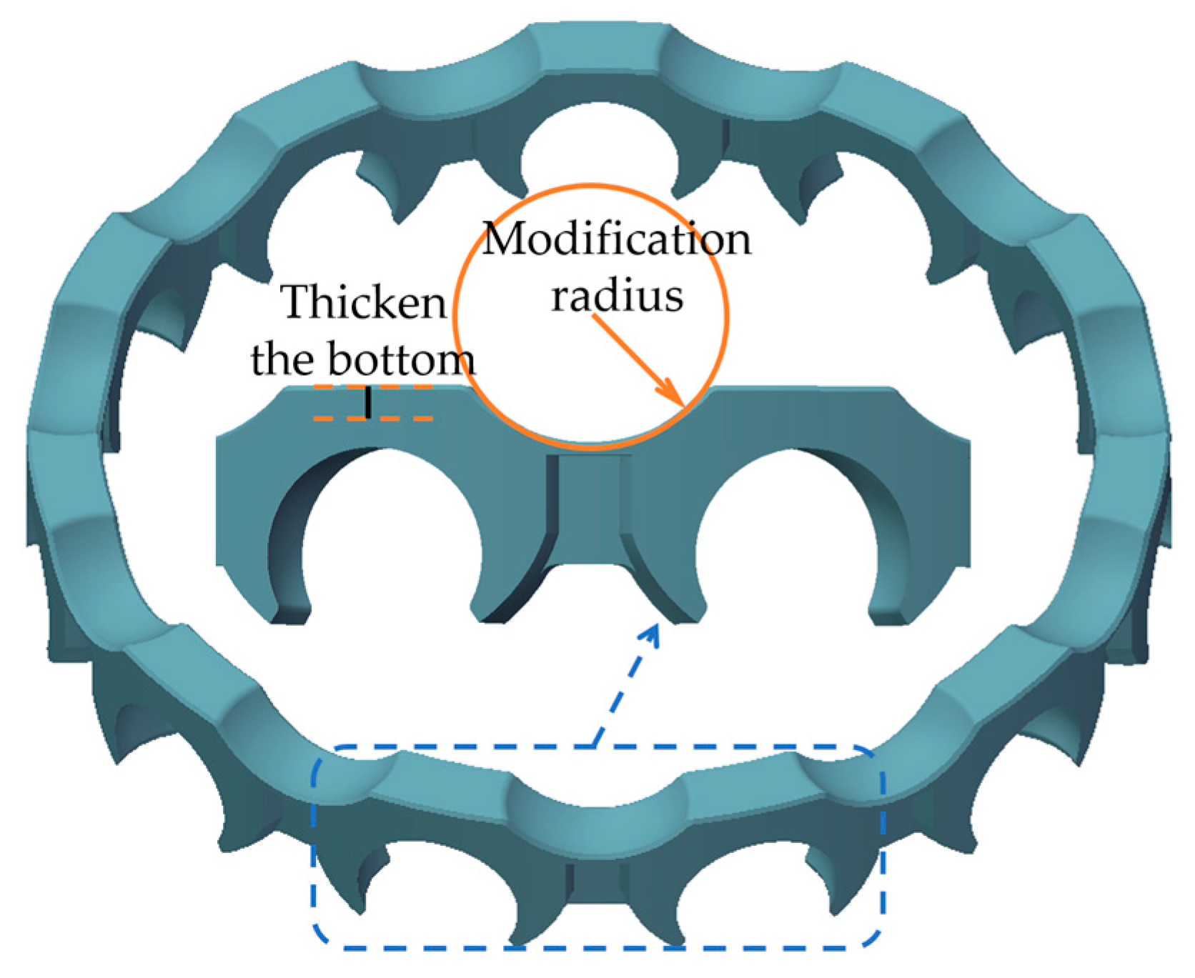
Increasing the pockets’ bottom thickness can enhance the cage strength and reduce the fractured risk. However, excessive thickness may impede the smooth operation of the cage and could potentially lead to interference in extreme cases. Therefore, determining the optimal pocket thickness is a critical factor in the cage strength design. As can be seen from Figure 12c, the optimal pocket bottom thickness is 2.4 mm. A schematic diagram illustrating the thickening of the pocket bottom is provided in Figure 13.
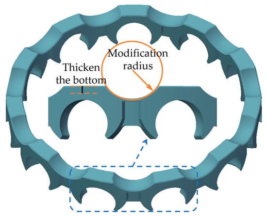
Figure 13.
Cage strength design plan (the blue dash square represents partial position of the cage.).
- (3)
- Reduce the influence of centrifugal force
When the bearing design parameters of the bearing, such as the diameter of the steel balls and the pitch circle diameter, are held constant, the centrifugal force within the cage primarily depends on the cage mass and the rotational speed of the bearing. However, the bearing speed is usually determined by the operating conditions and considering the previously discussed impact of cage mass on its strength; therefore, it is feasible to mitigate the centrifugal force by reducing the cage mass.
This section proposes a method for modifying the design by thickening the pocket bottom of the cage. This modified design not only decreases the cage mass and mitigates the adverse effects of centrifugal force at high speeds but also effectively prevents excessive deviation of the axial mass center of the cage from the pocket center, thereby improving the smooth operation of the cage.
Figure 12c demonstrates the effect of the modification radius on the cage strength. The observed trend reveals an initial decline in equivalent stress, followed by a subsequent increase, while the overall deformation continues to rise. This behavior can be attributed to the modified design, which alters the cage’s stiffness, enhances its flexibility, and results in significant deformation under centrifugal force and the load exerted by the steel ball, thereby reducing the cage’s equivalent stress. However, if the modification radius is excessively large, the increased flexibility may lead to excessive material removal, which would reduce the wall thickness of the adjacent structure and increase the cage’s equivalent stress. A modification radius reference value of 7.0 mm provides optimal cage strength.
4.4. Structural Verification
The primary differences between the two cages are as follows: Before the structural design, the beams connecting the pockets had a substantial mass, while the pocket strength was comparatively low. After the structural design, the beams between the pockets will be modified, with a radius adjustment of 7.0 mm, leading to a decrease in beam mass. Furthermore, the thickness of the pocket bottoms was increased by 1 mm.
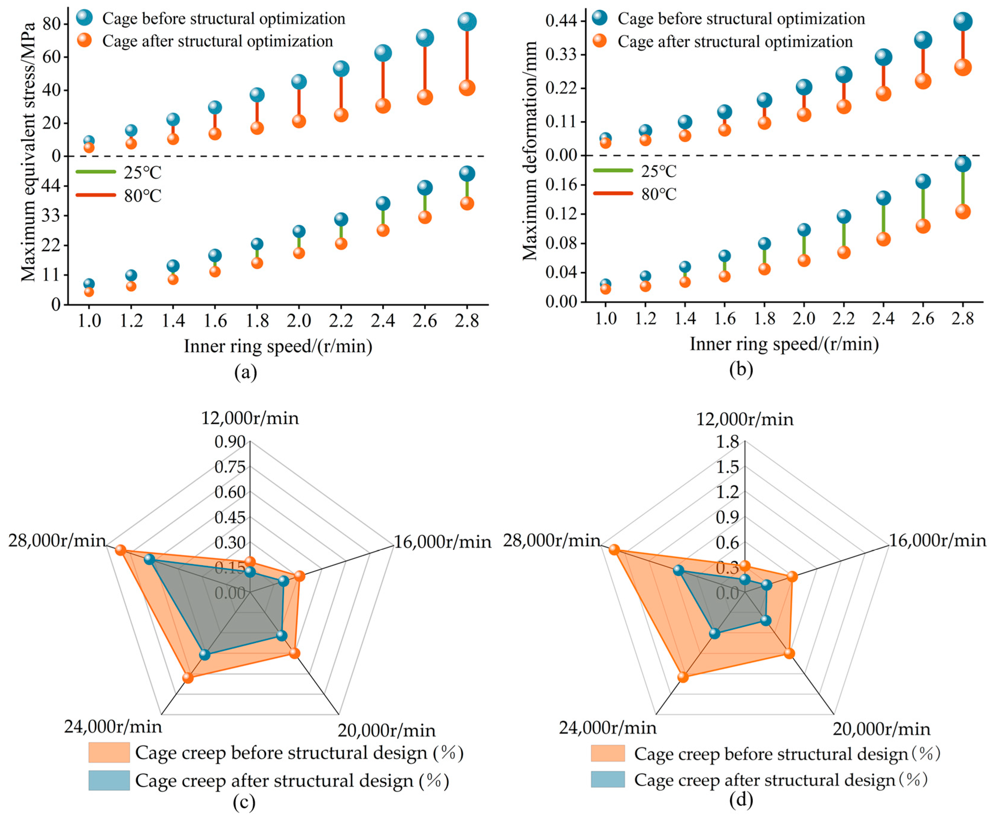
According to the working parameters shown in Table 1, the cage strength before and after the modified design was checked and calculated. The stress distribution in the cages, both before and after design modifications, is illustrated in Figure 14, while Figure 15a,b presents the results of stress and deformation under varying rotation speeds and temperatures.
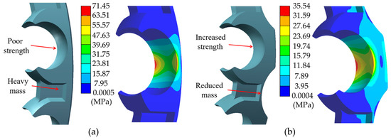
Figure 14.
Cage and stress cloud diagram before and after structural design. (a) Before the cage structure design; (b) After the cage structure design.
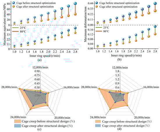
Figure 15.
Cage strength results before and after modification.
Figure 15a,b demonstrates that the pocket stress and the claw deformation after the structural design modifications is significantly lower, which is particularly pronounced at higher rotation speeds and temperatures. It can be seen that the cage structure modification design can significantly improve the cage strength.
The strain of PA46 + GF30 materials is greatly influenced by both rotational speed and temperature. According to the bearing working parameters given in Table 1, the strain calculation of the two cages was carried out, which is illustrated in Figure 15c (25 °C) and Figure 15d (80 °C). It is evident that, at varying temperatures and rotational speeds, the cage strain of the cage after structural design is significantly lower. Additionally, as temperature and rotational speed rise, the disparity in strain between the two cages becomes increasingly pronounced.
In summary, the cage after structural design is better suited for operation at high speeds and temperatures. Consequently, it is feasible to improve the structure of the cage.
5. Conclusions
This paper takes 6208 DGBBs as an example, systematically investigating how service conditions and the structural parameters of the cage influence its strength sensitivity. Based on the critical values of these parameters’ impact on strength, a structural design proposal is presented. The following conclusions are drawn:
- (1)
- The rotational speed is the primary factor influencing the sensitivity of cage strength. For every increase of 2000 r/min in the rotational speed, the stress and deformation of the cage increase by 15% to 20%. The acceleration mainly affects the cage stress amplitude, while it has little effect on cage strength. As the rotational speed increases, the sensitivity of cage strength to temperature obviously intensifies. The equivalent stress and radial deformation of the cage are elevated by 5%~16% at 80 °C, compared to 25 °C;
- (2)
- As the length of the claw increases, the stress initially decreases before rising again, while the deformation first increases and subsequently decreases. In contrast, as the modification radius increases, the stress exhibits a similar pattern of initial decrease followed by an increase, whereas the deformation consistently increases. Furthermore, an increase in the pocket thickness leads to a gradual decrease in stress, an increase in deformation. Conversely, an increase in the pocket gap results in an increase in stress and a decrease in deformation;
- (3)
- With a pocket clearance of 0.23 mm, a claw length of 2.3 mm, a bottom thickness of 2.4 mm, and a shaping radius of 7.0 mm, the strength of the cage was evaluated both before and after the improvements. The improved cage demonstrates a maximum reduction in equivalent stress of 22% to 34% at 25 °C, along with a maximum reduction in deformation of 33% to 39% in the radial direction, when compared to the pre-improvement cage. At 80 °C, the maximum equivalent stress is reduced by 50% to 55%, and the maximum deformation in the radial direction is reduced by 35% to 41%. The results indicated that the enhanced cage exhibited superior strength.
The influence of rolling elements on the cage depends on both the cage quality and the internal clearance of the bearing. Furthermore, the internal stress varies among different cage structures and materials. The nylon crown cages are highly susceptible to fractures, deformations, and vibrations under high-speed working conditions. In addition to the crown cage of the 6208 deep groove ball bearing examined in this study, the strength enhancement method proposed here is also applicable to the crown cages of other high-speed deep groove ball bearings, such as the 6306 and 6308 models. Furthermore, for other types of cages, such as the conventional cage with round pocket holes made from alloy steel, the bottom of the pocket hole may also experience failure due to fractures under severe working conditions. The methods and conclusions regarding cage strength improvement presented in this paper are based on the high-speed operational conditions of the crown cage within the current new energy vehicle electric drive system. However, the applicability of other types of cage strength improvement methods requires further exploration.
Author Contributions
Conceptualization, W.Z.; methodology, W.Z. and S.D.; software, W.Z. and S.D.; validation, W.Z., S.D. and H.T.; formal analysis, S.D.; investigation, L.H.; resources, H.T.; data curation, W.Z. and S.D.; writing—original draft preparation, W.Z. and S.D.; writing—review and editing, W.Z., S.D. and H.T.; visualization, S.D.; supervision, H.T. and L.H.; project administration, W.Z. All authors have read and agreed to the published version of the manuscript.
Funding
This research received no external funding.
Data Availability Statement
Data are contained within the article.
Conflicts of Interest
Author Li Huang was employed by the company CSC BEARING LTD. The remaining authors declare that the research was conducted in the absence of any commercial or financial relationships that could be construed as a potential conflict of interest.
Abbreviations
The following abbreviations are used in this paper:
| DGBB(s) | Deep Groove Ball Bearing(s) |
References
- He, F.; Xie, G.X.; Luo, J. Electrical bearing failures in electric vehicles. Friction 2020, 8, 4–28. [Google Scholar] [CrossRef]
- Qu, Y.F.; Mao, H.S. Key technologies and development trends of new energy vehicle electric drive systems. Era. Car. 2023, 15, 80–82. (In Chinese) [Google Scholar]
- Wang, P.F. Vibration characteristics of rotor-bearing system with angular misalignment and cage fracture: Simulation and experiment. Mech. Syst. Signal. Process. 2023, 182, 109545. [Google Scholar] [CrossRef]
- Chen, M.H. (63/22/C3) Bearing cage fracture failure analysis. Harbin. Bear. 2022, 43, 4. (In Chinese) [Google Scholar]
- Wang, M.; Yan, K. Dynamic performance analysis of ball bearings with multi-factor coupling excitation. Precis. Eng. 2024, 89, 70–90. [Google Scholar] [CrossRef]
- Thibault, N. Dynamic model of a deep grooves ball bearing dedicated to the study of instantaneous angular speed of rotating assemblies. Tribol. Int. 2022, 174, 107753. [Google Scholar] [CrossRef]
- Gillet, S. Cyclic creep strain rate criterion for short-fibre reinforced thermoplastics: Validation of creep and fatigue performance across a wide range of load ratios. Int. J. Fatigue 2024, 183, 108257. [Google Scholar] [CrossRef]
- Chen, Q.X. Structural Design and Dynamic Analysis of High-Speed Bearing Cage for Electric Drive of New Energy Vehicles. Master’s Thesis, Hunan University of Technology, Zhuzhou, China, 2023. (In Chinese). [Google Scholar]
- Li, T. Design and Performance Analysis of Key Components of Deep Groove Ball Bearings for High-Speed Motors for New Energy Vehicles. Master’s Thesis, Soochow University, Suzhou, China, 2020. (In Chinese). [Google Scholar]
- Ma, S.J. New bearing model with flexible cage and study of dynamic behavior under variable-speed. Mech. Syst. Signal. Process. 2024, 208, 111045. [Google Scholar] [CrossRef]
- Wang, M.K. Dynamic modeling and properties analysis for ball bearing driven by structure flexible deformations. Tribol. Int. 2023, 179, 108163. [Google Scholar] [CrossRef]
- Zhang, H.; Lei, X.L.; He, Y. Influence of appearance and working condition parameters on dynamic performance of bearing flexible cage. Flight Control Detect. 2021, 4, 7. [Google Scholar]
- Zhao, D.T.; Hong, J. Dynamic interaction between the rolling element and cage of rolling bearing considering cage flexibility and clearance. Mech. Mach. Theory 2022, 174, 104905. [Google Scholar] [CrossRef]
- Liu, Y.Q. Skidding dynamic performance of rolling bearing with cage flexibility under accelerating conditions. Mech. Syst. Signal. Process. 2021, 150, 107257. [Google Scholar] [CrossRef]
- Sadeghi, F. A Discrete Element Approach for Modeling Cage Flexibility in Ball Bearing Dynamics Simulations. J. Tribol. 2009, 131, 021102. [Google Scholar]
- Ashtekar, A. A New Approach for Including Cage Flexibility in Dynamic Bearing Models by Using Combined Explicit Finite and Discrete Element Methods. J. Tribol. 2012, 134, 041502. [Google Scholar] [CrossRef]
- Wang, M.K. Transient collision behavior and cage instable whirling mechanism in ball bearings: Modeling approach and properties investigation. Tribol. Int. 2023, 185, 108497. [Google Scholar] [CrossRef]
- Su, Y.; Zhang, J.Q. Theoretical and Experimental Approaches for Flexible Cage Dynamic Characteristics of Four-Point Contact Ball Bearing Considering Multi-Point Contact Behaviors. Mech. Syst. Signal Process. 2025, 223, 111929. [Google Scholar] [CrossRef]
- Yao, T.Q. Multibody dynamics simulation of thin-walled four-point contact ball bearing with interactions of balls, ring raceways and crown-type cage. Multibody Syst. Dyn. 2020, 48, 337–372. [Google Scholar] [CrossRef]
- Li, N. Research on Dynamic Modeling and Vibration Characterization of Integrated Bearings. Appl. Sci. 2024, 15, 98. [Google Scholar]
- Gao, S. Ultra-high-speed hybrid ceramic triboelectric bearing with real-time dynamic instability monitoring. Nano. Energy 2022, 103, 107759. [Google Scholar] [CrossRef]
- Cui, Y.C. Failure Inducement Factor Analysis and Optimal Design Method of Ball Bearing Cage for Aviation Motor. Machines 2024, 12, 466. [Google Scholar] [CrossRef]
- Yang, F. Study on the vibration characteristics of angular contact ball bearing cage under rolling-sliding compound motion. Meas. Sci. Technol. 2024, 35, 125125. [Google Scholar] [CrossRef]
- Cui, L. A new fatigue damage accumulation rating life model of ball bearings under vibration load. Ind. Lubr. Tribol. 2020, 72, 1205–1215. [Google Scholar] [CrossRef]
- Zhang, X.C. Characteristics and Mechanism of Surface Damage of Hybrid Ceramic Ball Bearings for High-Precision Machine Tool. Eng. Failure Anal. 2022, 142, 106784. [Google Scholar] [CrossRef]
- Fang, B.; Zhang, J.H. Analytical Determination of the Optimal Clearance for the Fatigue Life of Ball Bearing Under Different Load Conditions. J. Tribol. 2022, 144, 10. [Google Scholar] [CrossRef]
- Zeng, G. Study on the mass imbalance macro-micro friction and wear characteristics of high-speed angular contact ball bearing cages. Tribol. Int. 2025, 204, 110491. [Google Scholar] [CrossRef]
- Alarifi, I.M. A performance evaluation study of 3d printed nylon/glass fiber and nylon/carbon fiber composite materials. J. Mater. Res. Technol. 2022, 21, 884–892. [Google Scholar] [CrossRef]
- Gangben, C.S.R.; Huang, Z.Q.; Luo, J.W. Design and Calculation of Ball Bearing; China Machine Press: Beijing, China, 2003; pp. 171–175. [Google Scholar]
- Deng, S.E. Flexible body dynamics analysis of high-speed angular contact ball bearing cage. J. Ordnance. Ind. 2011, 32, 625–631. (In Chinese) [Google Scholar]
- Wang, G.X.; Niu, Z.P. Improved Craig–Bampton Method Implemented into Durability Analysis of Flexible Multibody Systems. Actuators 2023, 12, 65. [Google Scholar] [CrossRef]
- Benjamin, B. Interface reduction technique for Enhanced Craig-Bampton method. Mech. Syst. Signal. Process. 2024, 208, 111074. [Google Scholar]
- Jia, X.F. Research on vibration characteristics of high-speed ball bearing crown cage. Vib. Shock 2022, 41, 16–30. (In Chinese) [Google Scholar]


Disclaimer/Publisher’s Note: The statements, opinions and data contained in all publications are solely those of the individual author(s) and contributor(s) and not of MDPI and/or the editor(s). MDPI and/or the editor(s) disclaim responsibility for any injury to people or property resulting from any ideas, methods, instructions or products referred to in the content. |
© 2025 by the authors. Licensee MDPI, Basel, Switzerland. This article is an open access article distributed under the terms and conditions of the Creative Commons Attribution (CC BY) license (https://creativecommons.org/licenses/by/4.0/).