
Dynamic Characteristics Analysis and Optimization Design of Two-Stage Helix Planetary Reducer for Robots

Abstract
1. Introduction
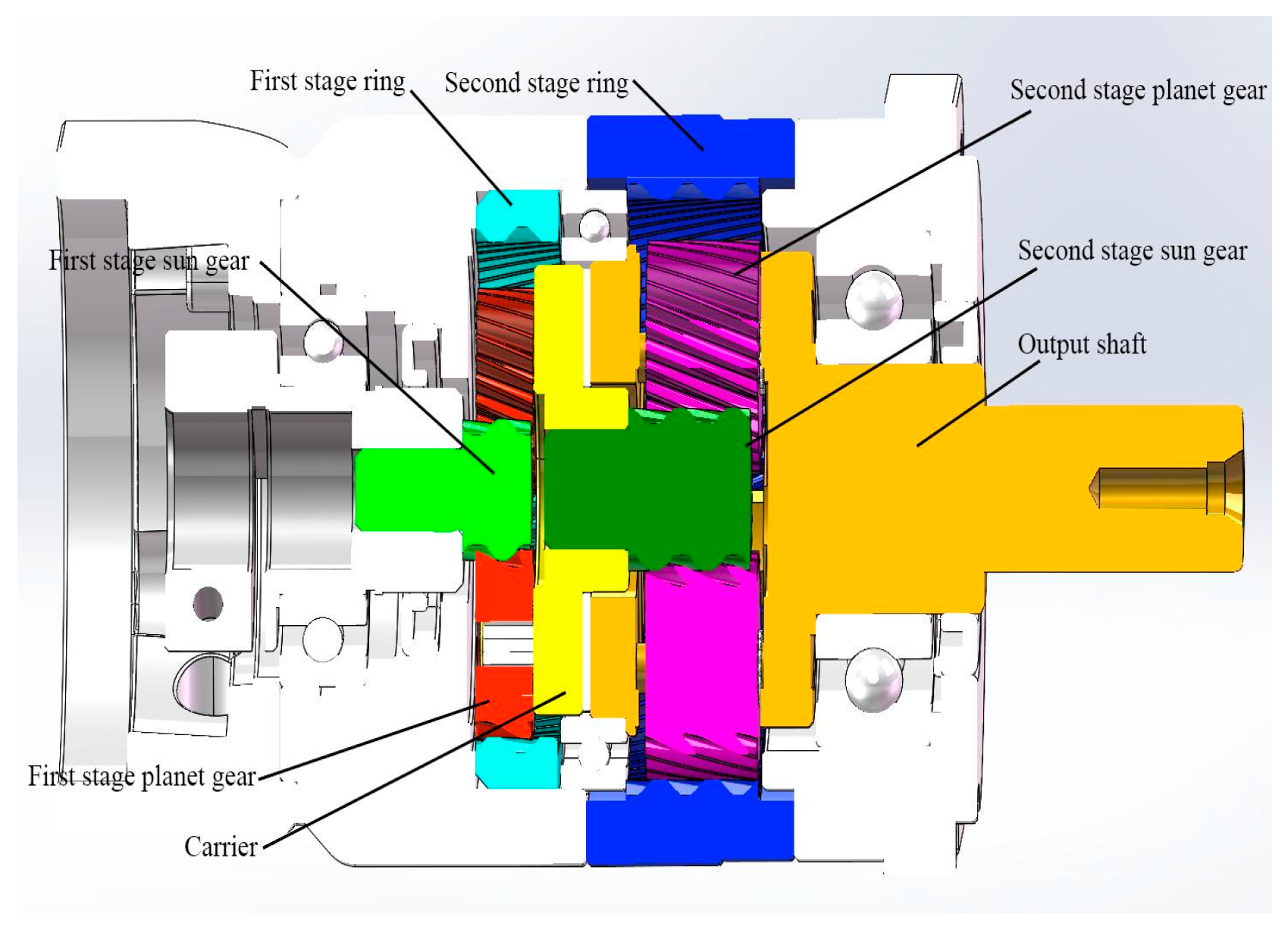
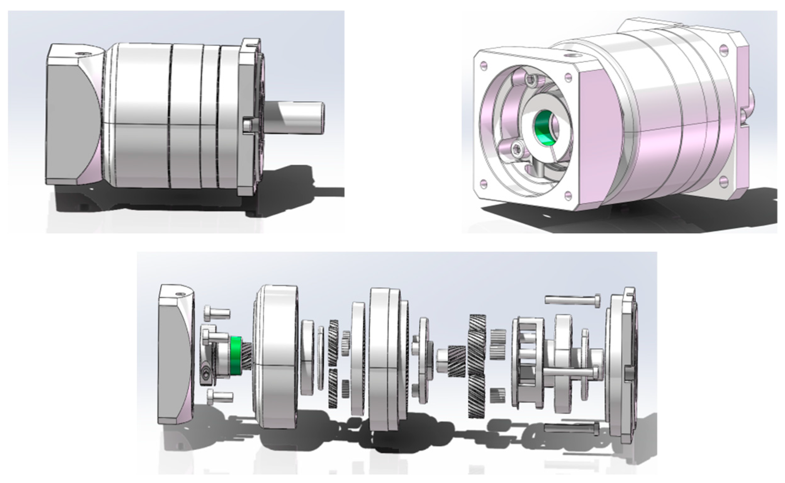
2. Transmission Principle of a Two-Stage Helix Planetary Reducer
- Planetary gears, consisting of three identical helical external gears symmetrically installed at 120°.
- The sun gear, the power input component, which is an external gear conjugate to the helical planetary gears.
- The ring gear, which is fixed to the housing and meshed with helical planetary external gears.
- The power output mechanism, comprising power transmission components, where the first-stage power output mechanism is the planet carrier, and the second stage is the output shaft.
3. Establishment of the Dynamic Theoretical Model of a Two-Stage Helix Planetary Reducer
3.1. Basic Assumptions and Coordinate Systems
- Simplify planetary gear drive into a centralized parameter system.
- Only the vibration of components of the planetary gear system in the torsional direction is considered.
- The gear body and carrier are rigid bodies, and the meshing relationship between the gears is simplified as a spring–damping system.
- Ignore the influence of gear tooth side clearance, gravity, and other factors.
- The drive shaft connection between two adjacent planetary gear systems is simplified as a torsion spring.
3.2. Mesh Stiffness Excitation and Transmission Error Excitation Analysis
3.2.1. Mesh Stiffness Excitation
3.2.2. Transmission Error Excitation
3.3. Formatting of Mathematical Components
3.3.1. Relative Displacements
3.3.2. Motion Equations
3.4. Theory of Modal Analysis
4. Establishment of Finite Element Model and Modal Analysis
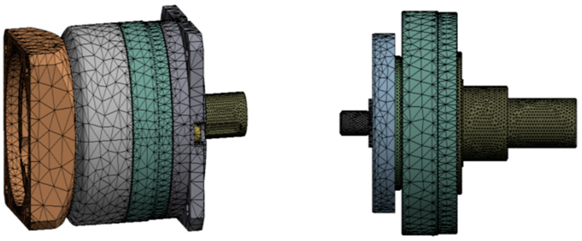
4.1. Establishing the Finite Model
4.2. Validation of the Finite Element Model
4.3. Modal Analysis
5. Analysis of Vibration Characteristics of High-Precision Reducer
5.1. Simulation of Vibration Characteristics
5.2. Test of Vibration Characteristics
5.2.1. Vibration Testing Method and Equipment
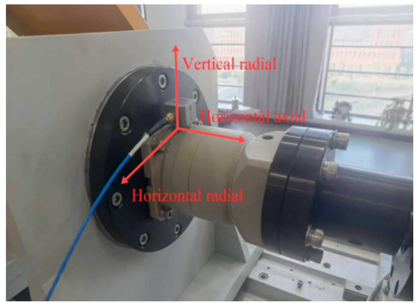
5.2.2. Measurement Point Arrangement
5.2.3. Reducer Vibration Test Results
5.3. Analysis of Results
5.3.1. Analysis of Peak-to-Peak Value and Eigenvalue
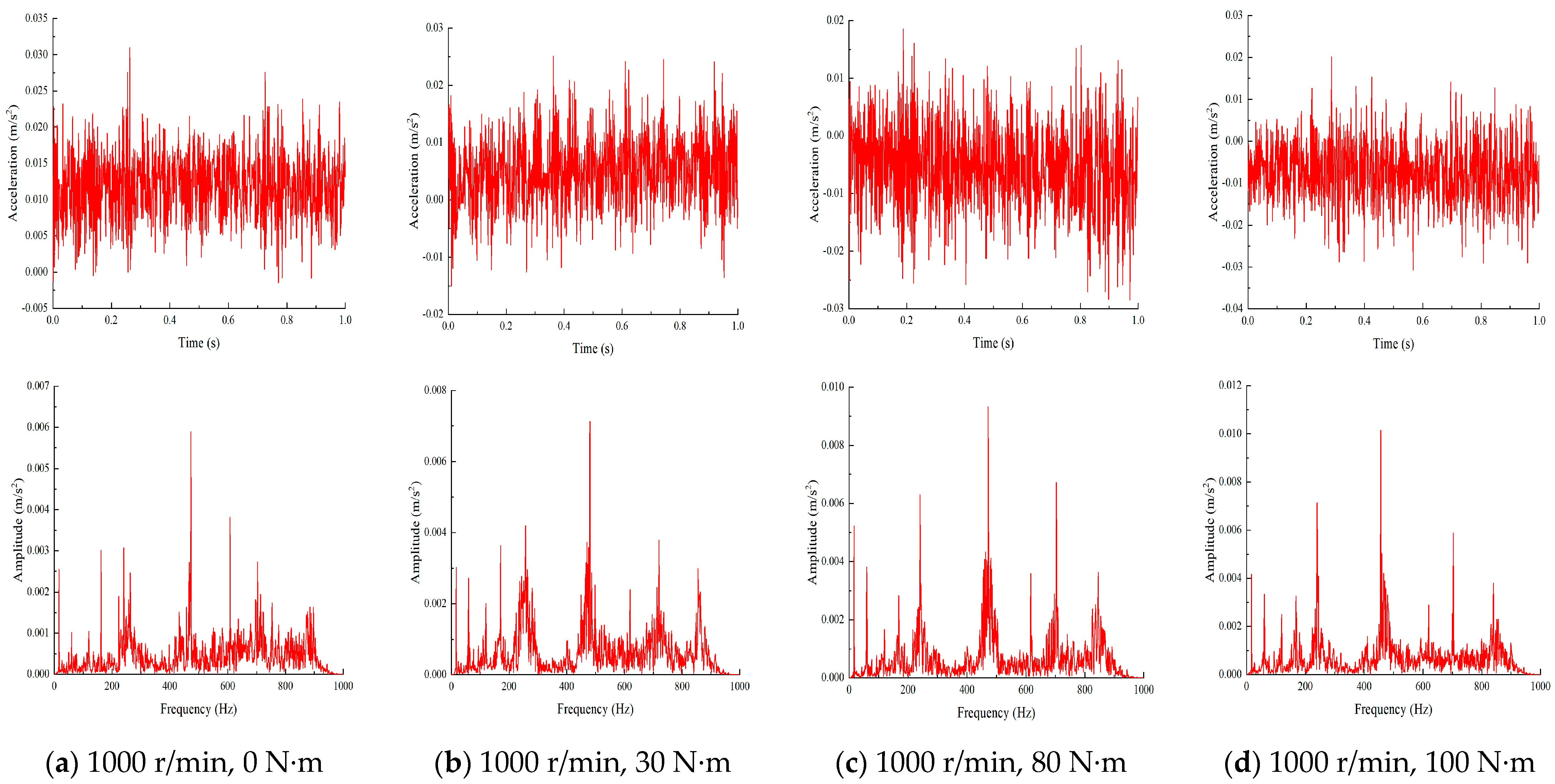
5.3.2. Spectrum Analysis
5.3.3. Analysis of Influencing Factors
6. Analysis of Transmission Error of High-Precision Reducer
6.1. Test of Transmission Error
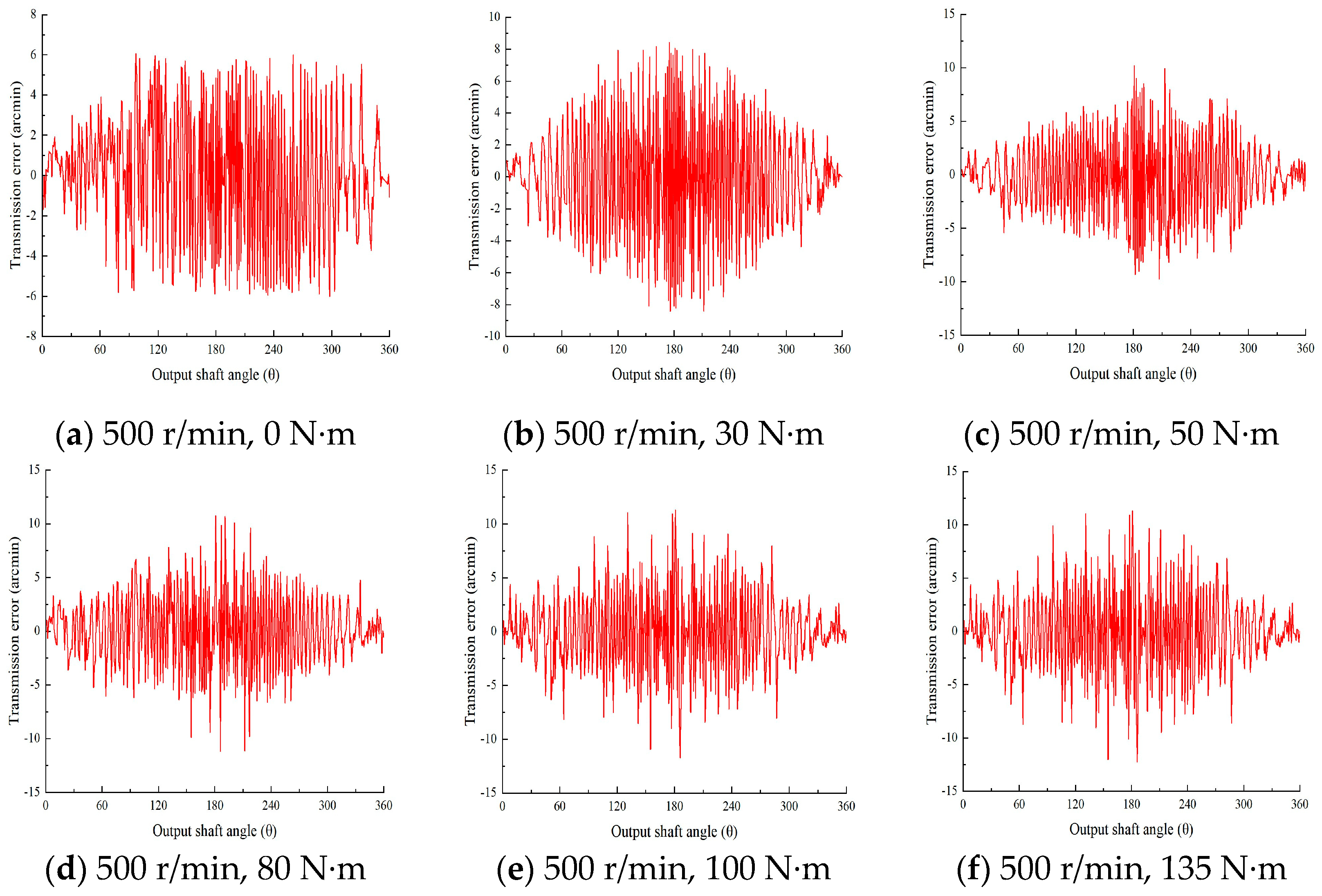
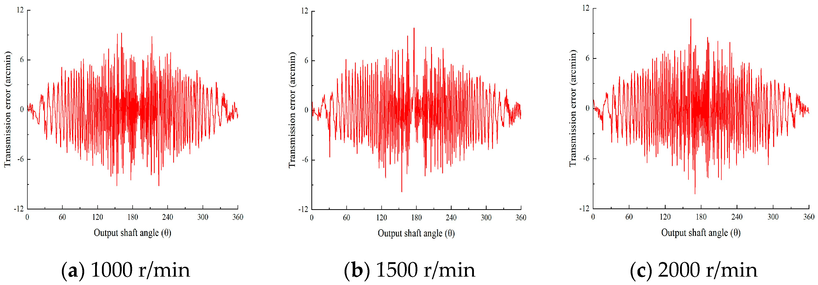
6.2. Analysis of Transmission Error
7. Optimization Design of High-Precision Reducer
7.1. Gear Modification
7.1.1. Modification of Tooth Contours
7.1.2. Modification of Tooth Orientation
7.2. Shape Optimization for Gear Teeth
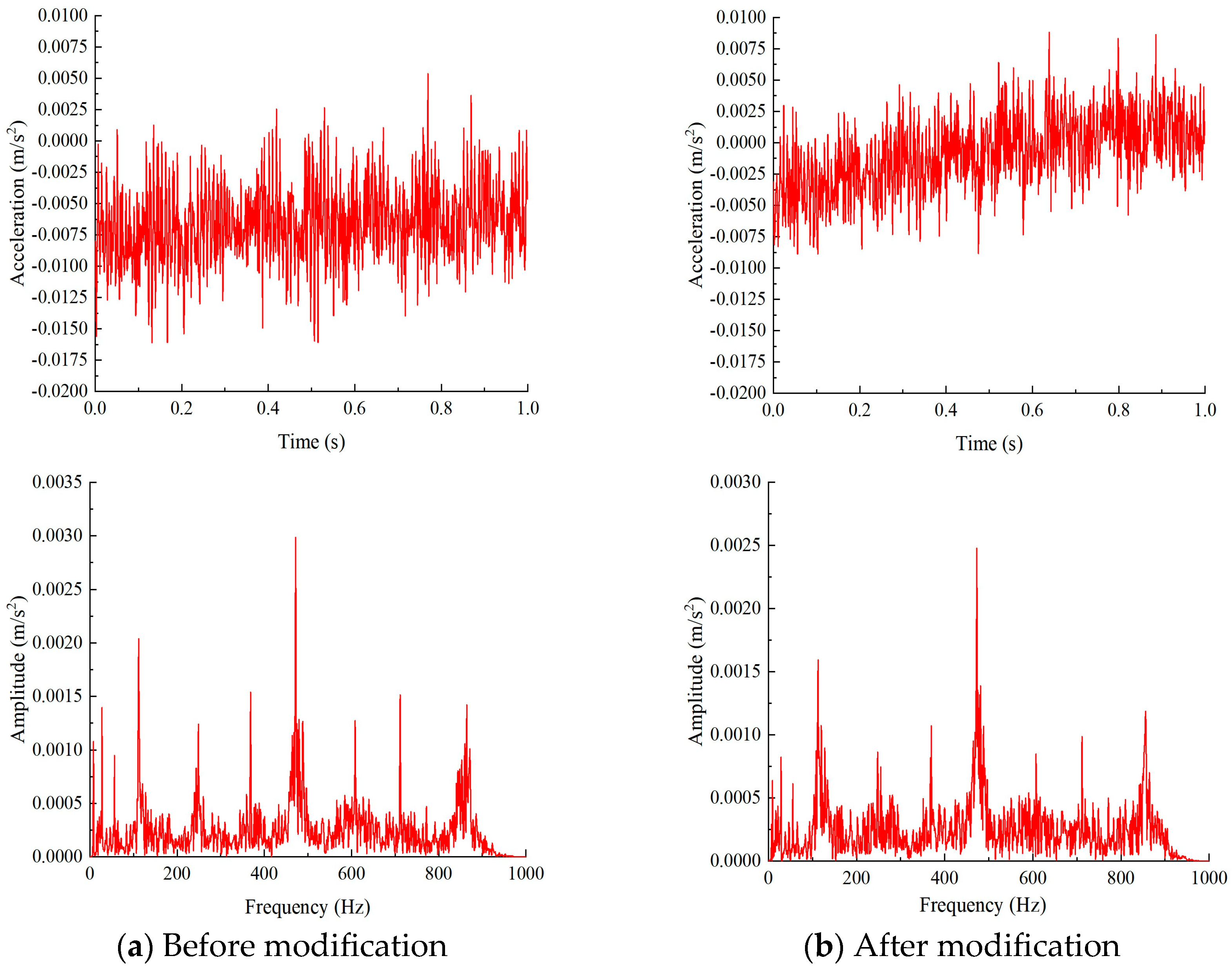
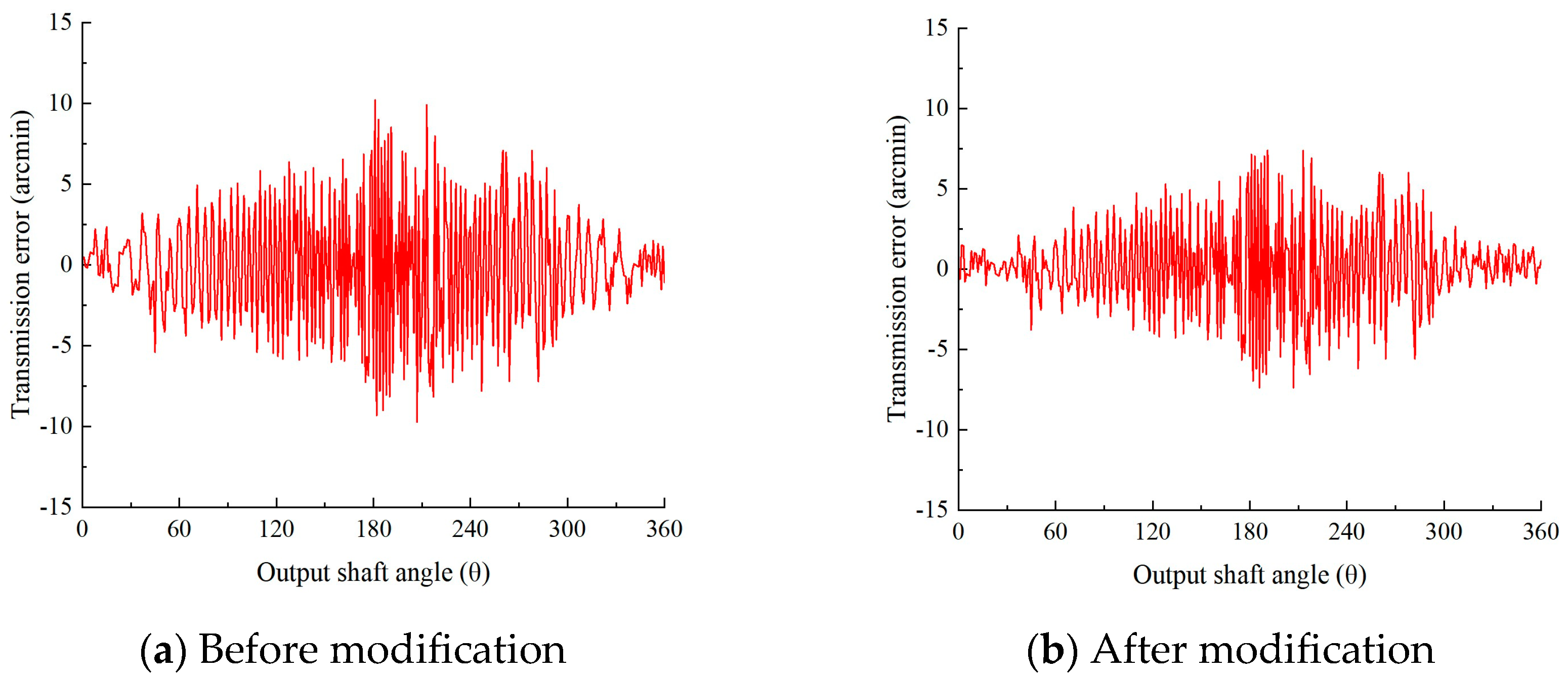
7.3. Simulation Analysis
8. Conclusions
- The first 10th-order intrinsic frequency and modal shapes of a two-stage gear train of a high-precision planetary reducer in the meshing state are simulated. The analysis results show that the most likely resonance locations in the planetary reducer are the planetary gears, the planetary carrier, and the output shaft.
- Vibration tests are conducted on the high-precision planetary reducer using a comprehensive performance testing platform. The acceleration vibration signals of the high-precision planetary reducer at different rotate speeds and torques are also obtained through dynamic simulation. Analysis of the simulation and test signals indicates that the vibration of the high-precision reducer is influenced by both load and speed. The load mainly affects the time-domain distribution of the vibration signal, with relatively minor effects on the frequency-domain distribution, whereas the speed has a significant impact on both.
- Based on the experimental test, as the load torque increases, the transmission error amplitude of the reducer increases, but the amplitude growth rate is gradually decreased. The amplitude of transmission error at no load is 12.16 arcmin, and the amplitude of transmission error at rated torque is 23.16 arcmin, which is an increase of 90.46%.The amplitude of transmission error at 500 r/min is 16.80 arcmin, and the amplitude of transmission error at 2000 r/min is 20.94 arcmin, which is an increase of 24.64%. Therefore, load has a large impact on the transmission error, while the input speed has a relatively small impact on the transmission error, so a variety of factors should be considered in the design.
- Using the helix modification with drum shape, the peak-to-peak value of the transmission error of the gearbox is reduced from 18.42 arcmin to 14.76 arcmin, a reduction of 19.87%, and the peak-to-peak value of the vibration acceleration is reduced from 0.021 m/s2 before the modification to 0.018 m/s2, a reduction of 14.29%, for an input speed of 500 r/min and a load of 50 N·m. The RMS value is reduced from 0.0038 before the modification to 0.003, a reduction of 21.05%; The RMS value is reduced from 0.0038 before shape offset to 0.0030, which is 21.05% lower. The helix modification with drum shape improves the transmission accuracy of the overall gear system, reduces the noise in the transmission, and makes the gear system transmission smoother. It has greater accuracy than previous optimization design methods, can obtain the optimal solution quickly and iteratively, improves the design efficiency and design quality, has better practical value, and provides a relevant basis for exploring the combined modification.
Author Contributions
Funding
Data Availability Statement
Conflicts of Interest
References
- Peng, P.; Ke, L.; Wang, J. Fault diagnosis of RV reducer with noise interference. J. Mech. Eng. 2020, 56, 30–36. [Google Scholar] [CrossRef]
- Xiao, X.; Hu, D.; Li, G.; Luo, L.; Gong, L.; Lou, J. Modal vibration characteristic analysis of crank shaft of the high-precision RV reducer under meshing state. J. Mech. Transm. 2021, 45, 134–138. [Google Scholar] [CrossRef]
- Pham, A.; Ahn, H. High precision reducers for industrial robots driving 4th industrial revolution: State of arts, analysis, design, performance evaluation and perspective. Int. J. Precis. Eng. Manuf. -Green Technol. 2018, 5, 519–533. [Google Scholar] [CrossRef]
- Huang, X.; He, Y.; Fu, Y. Summary of precision speed reducer of industrial robots. Mach. Tool Hydraul. 2015, 43, 1–6. [Google Scholar] [CrossRef]
- Yang, F.; Zhou, X.; Xu, H. Nonlinear vibration characteristics of two-stage gear reducer. J. Zhejiang Univ. (Eng. Sci.) 2009, 43, 1243–1248. [Google Scholar] [CrossRef]
- Hu, Y.; Talbot, D.; Kahraman, A. A load distribution model for planetary gear sets. J. Mech. Des. 2018, 140, 053302. [Google Scholar] [CrossRef]
- Vasić, M.; Blagojevic, M.; Stojic, B.; Dizdar, S. Design and performance analysis of an in-wheel hub reducer. Adv. Eng. Lett. 2022, 1, 115–125. [Google Scholar] [CrossRef]
- Stanojević, M.; Tomović, R.; Ivanović, L.; Stojanovic, B. Critical analysis of design of ravigneaux planetary gear trains. Adv. Eng. Lett. 2022, 7, 32–44. [Google Scholar] [CrossRef]
- Kahraman, A.; Singh, R. Non-linear dynamics of a geared rotor-bearing system with multiple clearances. J. Sound Vib. 1991, 144, 469–506. [Google Scholar] [CrossRef]
- Ambarisha, V.; Parker, R.G. Nonlinear dynamics of planetary gears using analytical and finite element models. J. Sound Vib. 2007, 302, 577–595. [Google Scholar] [CrossRef]
- Li, G.; Wu, J.; Li, H. Analysis of torsional vibration of bevoloid RV reducer system. J. Mech. Transm. 1999, 23, 20–22. [Google Scholar] [CrossRef]
- Wang, J.; Ke, L. Vibration characteristics of a RV reducer. J. Vib. Shock. 2020, 39, 57–63. [Google Scholar] [CrossRef]
- Li, J.; Kang, B.; Sun, Y.; Huang, Y.; Guo, J.; Gao, Z. Dynamic Characteristic Analysis of the Shield Machine Three-Stage Planetary Reducer Considering Tooth Wear. J. Vib. Eng. Technol. 2024, 12, 7291–7304. [Google Scholar] [CrossRef]
- Du, X.; Huang, Y.; Zhu, C.; Ullah, N.; Hu, R.; Qi, C. Dynamic characteristics analysis of variable tooth thickness RV reducer. J. Vib. Shock. 2020, 39, 250–257. [Google Scholar] [CrossRef]
- Xu, L.; Xia, C.; Yang, B. Analysis and Test on Dynamic Transmission Errors of RV Reducers under Load Conditions. China Mech. Eng. 2023, 34, 2143–2152. [Google Scholar] [CrossRef]
- Li, Y.; Yuan, S.; Wu, W.; Song, X.; Liu, K.; Lian, C. Dynamic analysis of the helical gear transmission system in electric vehicles with a large helix angle. Machines 2023, 11, 696. [Google Scholar] [CrossRef]
- Han, Z.; Wang, H.; Li, R.; Shan, W.; Zhao, Y.; Hu, X. Study on Nonlinear Dynamic Characteristics of RV Reducer Transmission System. Energies 2024, 17, 1178. [Google Scholar] [CrossRef]
- Zhou, J.; Sun, W.; Cao, L. Vibration and noise characteristics of a gear reducer under different operation conditions. Journal of Low Frequency Noise. Vib. Act. Control. 2024, 38, 574–591. [Google Scholar] [CrossRef]
- Li, X.; Huang, J.; Ding, C.; Guo, R.; Niu, W. Dynamic modeling and analysis of an RV reducer considering tooth profile modifications and errors. Machines 2023, 11, 626. [Google Scholar] [CrossRef]
- Guo, D.; Ning, Q.; Ge, S.; Wang, Y.; Zhou, Y.; Zhou, Y.; Shi, X. Nonlinear characteristic analysis of gear rattle based on refined dynamic model. Nonlinear Dyn. 2022, 110, 3109–3133. [Google Scholar] [CrossRef]
- Zhang, J.; Zhou, J.; Wang, S.; Lu, F. Research on dynamic characteristics and radiation noise of a helicopter main reducer based on finite element and boundary element method. J. Mech. Sci. Technol. 2023, 37, 4489–4505. [Google Scholar] [CrossRef]
- Jin, P.; Zhou, J.; Qi, L. Dynamic optimization of two-stage reducer considering design and layout parameters. J. Vib. Shock 2023, 42, 259–268. [Google Scholar] [CrossRef]
- Qin, D.; Zhao, Y. Multi-objective Optimization of Multi-stage Planetary Gear Train Used in Shield Machine Cutter Driver. China Mech. Eng. 2012, 23, 12–17. [Google Scholar] [CrossRef]
- Ghosh, S.; Chakraborty, G. On optimal tooth profile modification for reduction of vibration and noise in spur gear pairs. Mech. Mach. Theory 2016, 105, 145–163. [Google Scholar] [CrossRef]
- Xin, W.; Zhang, Y.; Fu, Y.; Yang, W.; Zheng, H. A multi-objective optimization design approach of large mining planetary gear reducer. Sci. Rep. 2023, 13, 18640. [Google Scholar] [CrossRef] [PubMed]
- Liu, C.; Chen, L.; Lee, H.; Yang, Y.; Zhang, X. A review of the inerter and inerter-based vibration isolation: Theory, devices, and applications. J. Frankl. Inst. 2022, 359, 7677–7707. [Google Scholar] [CrossRef]
- Portron, S.; Velex, P.; Abousleiman, V. A hybrid model to study the effect of tooth lead modifications on the dynamic behavior of double helical planetary gears. Proc. Inst. Mech. Eng. Part C J. Mech. Eng. Sci. 2019, 233, 7224–7235. [Google Scholar] [CrossRef]
- Qiu, X.; Han, Q.; Chu, F. Dynamic modeling and analysis of the planetary gear under pitching base motion. Int. J. Mech. Sci. 2018, 141, 31–45. [Google Scholar] [CrossRef]
- Lin, J.; Parker, R. Analytical characterization of the unique properties of planetary gear free vibration. J. Vib. Acoust. 1999, 121, 316–321. [Google Scholar] [CrossRef]
- Bao, S. Analysis and Experimental Study on Static-Dynamic Characteristics of Precision Planetary Reducer Transmission System for Robot. Master’s Thesis, Jiangxi University of Science and Technology, Ganzhou, China, 2020. [Google Scholar]
- Inalpolat, M.; Kahraman, A. Dynamic modelling of planetary gears of automatic transmissions. Proc. Inst. Mech. Eng. Part K J. Multi-Body Dyn. 2008, 222, 229–242. [Google Scholar] [CrossRef]
- Meng, C.; Chen, C.; Yang, Y. Modal Characteristic Analysis of RV Reducers. China Mech. Eng. 2018, 29, 8–13. [Google Scholar] [CrossRef]
- GB/T 8543-1987; Determination of Mechanical Vibrations of Gear Units During Acceptance Testing. Standardization Administration of China: Beijing, China, 1987.
- Goyal, D.; Vanraj; Pabla, B.; Dhami, S. Condition monitoring parameters for fault diagnosis of fixed axis gearbox: A review. Arch. Comput. Methods Eng. 2017, 24, 543–556. [Google Scholar] [CrossRef]
- Kundu, P.; Darpe, A.; Kulkarni, M. A review on diagnostic and prognostic approaches for gears. Struct. Health Monit. 2021, 20, 2853–2893. [Google Scholar] [CrossRef]
- Qian, B. Study on Transient Dynamics of Two-stage Planetary Gear Reducer. Master’s Thesis, Chongqing University, Chongqing, China, 2014. [Google Scholar]
- Xu, H.; Liu, W.; Cui, J.; Wei, C. Optimization design and simulation analysis of precision planetary reducer. Mach. Tool Hydraul. 2023, 51, 193–197. [Google Scholar] [CrossRef]
- Wang, C.; Shi, P. Optimal modification of helical gear tooth surface based on KISSsoft. J. Mech. Transm. 2018, 42, 85–90. [Google Scholar] [CrossRef]
- Wang, X.; Wang, Y.; Liu, Y.; Zhang, X.; Zheng, D. Multi-objective optimization modification of a tooth surface with minimum of flash temperature and vibration acceleration RMS. J. Mech. Sci. Technol. 2018, 32, 3097–3106. [Google Scholar] [CrossRef]
- Mohammed, O.D.; Rantatalo, M.; Aidanpää, J.O. Dynamic modelling of a one-stage spur gear system and vibration-based tooth crack detection analysis. Mech. Syst. Signal Process. 2015, 54, 293–305. [Google Scholar] [CrossRef]


| Basic Parameters | Carrier | Sun Gear | Planet Gear | Ring |
|---|---|---|---|---|
| The parameters of the first-stage planetary gear system | ||||
| Mass (g) | 135.65 | 22.06 | 18.97 | 99.90 |
| Number of teeth | - | 18 | 27 | 72 |
| Moment of inertia Ii (kg·mm2) | 0.4878 | 0.4849 | 1.5319 | 48.817 |
| Base circle diameter (mm) | - | 15.32 | 22.99 | 60.08 |
| Pressure angle (°) | - | 20 | 20 | 20 |
| Helix angle (°) | - | 20 | 20 | 20 |
| Number of planet gears | 3 | |||
| Modulus | 0.8 | |||
| The parameters of the second-stage planetary gear system | ||||
| Mass (g) | 485.64 | 47.53 | 56.96 | 465.52 |
| Number of teeth | - | 21 | 31 | 84 |
| Moment of inertia Ii (kg·mm2) | 144.21 | 1.6813 | 5.4764 | 143.92 |
| Base circle diameter (mm) | - | 17.88 | 26.39 | 69.205 |
| Pressure angle (°) | - | 20 | 20 | 20 |
| Helix angle (°) | - | 20 | 20 | 20 |
| Number of planet gears | 3 | |||
| Modulus | 0.8 | |||
| Input Speed /(r/min) | 500 | 1000 | 1500 | 2000 |
|---|---|---|---|---|
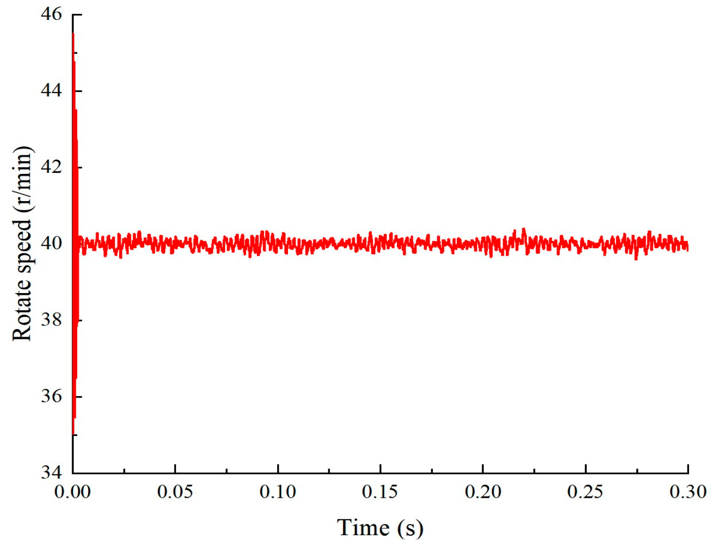
| Output speed /(r/min) | 19.981 | 40.009 | 59.990 | 80.017 |
| 20.027 | 39.986 | 60.013 | 79.994 | |
| 20.004 | 39.963 | 59.970 | 79.971 | |
| 19.958 | 40.009 | 60.036 | 80.020 | |
| 20.004 | 40.031 | 60.008 | 79.986 |
| Part | Material | Density /(kg/m3) | Elasticity Modulus /105 MPa | Poisson’s Ratio |
|---|---|---|---|---|
| Sun gear | 20CrMnTi | 7800 | 2.07 | 0.25 |
| Planet gear | 20CrMnTi | 7800 | 2.07 | 0.25 |
| Carrier | 40Cr | 7850 | 2.0 | 0.3 |
| Needle roller | GCr15 | 7830 | 2.19 | 0.3 |
| Order | Natural Frequency/Hz | Modal Shape |
|---|---|---|
| 1 | 2193.1 | Twisting around the X-axis |
| 2 | 3155.7 | Twisting in plane xoy |
| 3 | 3529 | Twisting in plane xoz |
| 4 | 4313 | Twisting around the X-axis |
| 5 | 5909.3 | Twisting around the X-axis |
| 6 | 6284.7 | Twisting around the X-axis |
| 7 | 6456.4 | Twisting in plane xoz |
| 8 | 6646.3 | Bending in plane xoy |
| 9 | 7777.7 | Bending in plane xoz |
| 10 | 7988.6 | Bending in plane xoy |
| Name | Model Number |
|---|---|
| Input motor | 1FL6062-1AC61-2LA1 |
| Input torque sensor | ZJ-30A |
| Tested planetary reducer | 90AF25-750T3WL |
| Angle encoder | TS5236N120 |
| Output torque sensor | ZJ-200A |
| Output reducer | 142ZB10-2000T5 |
| Output motor | 1FL6090-1AC61-2LA1 |
| Vibration acceleration sensor | CT1010SLFP 211210 |
| Control acquisition instrument | NI cDAQ-9137 |
| Load /(N·m) | Speed /(r·min−1) | Simulation Peak-to-Peak Value/(m·s−2) | Test Peak-to-Peak Value/(m·s−2) |
|---|---|---|---|
| 0 | 500 | 0.016 | 0.015 |
| 1000 | 0.032 | 0.031 | |
| 1500 | 0.065 | 0.064 | |
| 2000 | 0.080 | 0.080 | |
| 30 | 500 | 0.018 | 0.017 |
| 1000 | 0.040 | 0.040 | |
| 1500 | 0.067 | 0.068 | |
| 2000 | 0.087 | 0.086 | |
| 50 | 500 | 0.022 | 0.021 |
| 1000 | 0.064 | 0.045 | |
| 1500 | 0.078 | 0.079 | |
| 2000 | 0.093 | 0.094 | |
| 80 | 500 | 0.02 | 0.024 |
| 1000 | 0.050 | 0.048 | |
| 1500 | 0.084 | 0.085 | |
| 2000 | 0.099 | 0.098 | |
| 100 | 500 | 0.029 | 0.030 |
| 1000 | 0.053 | 0.051 | |
| 1500 | 0.088 | 0.088 | |
| 2000 | 0.104 | 0.103 |
| Load /(N·m) | Speed /(r·min−1) | Simulation RMS | Test RMS | Relative Error |
|---|---|---|---|---|
| 0 | 500 | 0.0033 | 0.0034 | 2.9% |
| 1000 | 0.0058 | 0.0056 | 3.6% | |
| 1500 | 0.0102 | 0.0108 | 5.5% | |
| 2000 | 0.0201 | 0.0198 | 1.5% | |
| 30 | 500 | 0.0034 | 0.0037 | 8.1% |
| 1000 | 0.0060 | 0.0062 | 3.2% | |
| 1500 | 0.0115 | 0.0114 | 0.9% | |
| 2000 | 0.0227 | 0.0238 | 4.6% | |
| 50 | 500 | 0.0035 | 0.0038 | 7.9% |
| 1000 | 0.0068 | 0.0070 | 2.9% | |
| 1500 | 0.0124 | 0.0128 | 3.1% | |
| 2000 | 0.0250 | 0.0271 | 7.7% | |
| 80 | 500 | 0.0037 | 0.0039 | 5.1% |
| 1000 | 0.0070 | 0.0077 | 9.1% | |
| 1500 | 0.0139 | 0.0145 | 4.1% | |
| 2000 | 0.0298 | 0.0319 | 6.6% | |
| 100 | 500 | 0.0040 | 0.0043 | 7.0% |
| 1000 | 0.0073 | 0.0078 | 6.4% | |
| 1500 | 0.0148 | 0.0159 | 6.9% | |
| 2000 | 0.0359 | 0.0377 | 4.8% |
| Speed (r/min) | 500 | 1000 | 1500 | 2000 |
|---|---|---|---|---|
| The meshing frequency of the sun gear | 8.33 | 16.67 | 25.00 | 33.33 |
| The meshing frequency of the first transmission system | 120 | 240 | 360 | 480 |
| The meshing frequency of the second transmission system | 28 | 56 | 84 | 112 |
Disclaimer/Publisher’s Note: The statements, opinions and data contained in all publications are solely those of the individual author(s) and contributor(s) and not of MDPI and/or the editor(s). MDPI and/or the editor(s) disclaim responsibility for any injury to people or property resulting from any ideas, methods, instructions or products referred to in the content. |
© 2025 by the authors. Licensee MDPI, Basel, Switzerland. This article is an open access article distributed under the terms and conditions of the Creative Commons Attribution (CC BY) license (https://creativecommons.org/licenses/by/4.0/).
Share and Cite
Lin, W.; Chang, D.; Li, H.; Chen, J.; Huang, F. Dynamic Characteristics Analysis and Optimization Design of Two-Stage Helix Planetary Reducer for Robots. Machines 2025, 13, 245. https://doi.org/10.3390/machines13030245
Lin W, Chang D, Li H, Chen J, Huang F. Dynamic Characteristics Analysis and Optimization Design of Two-Stage Helix Planetary Reducer for Robots. Machines. 2025; 13(3):245. https://doi.org/10.3390/machines13030245
Chicago/Turabian StyleLin, Wenzhao, Dongdong Chang, Hao Li, Junhua Chen, and Fangping Huang. 2025. "Dynamic Characteristics Analysis and Optimization Design of Two-Stage Helix Planetary Reducer for Robots" Machines 13, no. 3: 245. https://doi.org/10.3390/machines13030245
APA StyleLin, W., Chang, D., Li, H., Chen, J., & Huang, F. (2025). Dynamic Characteristics Analysis and Optimization Design of Two-Stage Helix Planetary Reducer for Robots. Machines, 13(3), 245. https://doi.org/10.3390/machines13030245